Abstract
It has become increasingly preferable to construct bespoke software development processes according to the specifications of the project at hand; however, defining a separate process for each project is time consuming and costly. One solution is to use a Software Process Line (SPrL), a specialized Software Product Line (SPL) in the context of process definition. However, instantiating an SPrL is a slow and error-prone task if performed manually; an adequate degree of automation is therefore essential, which can be achieved by using a Model-Driven Development (MDD) approach. Furthermore, we have identified specific shortcomings in existing approaches for SPrL Engineering (SPrLE). To address the identified shortcomings, we propose a novel MDD approach specifically intended for SPrLE; this approach can be used by method engineers and project managers to first define an SPrL, and then construct custom processes by instantiating it. The proposed approach uses a modeling framework for modeling an SPrL, and applies transformations to provide a high degree of automation when instantiating the SPrL. The proposed approach addresses the shortcomings by providing an adequate coverage of four activities, including Feasibility analysis, Enhancing the core process, Managing configuration complexity, and Post-derivation enhancement. The proposed approach has been validated through an industrial case study and an experiment; the results have shown that the proposed approach can improve the processes being used in organizations, and is rated highly as to usefulness and ease of use.
1. Introduction
The software process (also referred to as software development methodology/method) is a critical factor in developing quality software systems, as it helps transform user needs into a software product that satisfies those needs [1]. There is no software process suitable for all development situations [2], as the suitability of a process depends on various product, project, and organizational characteristics [3]. Thus, building custom processes has become critical for software development organizations [4]; however, defining a specific process for each and every project is a time-consuming and costly endeavor [5]. Method tailoring is an effective approach for building bespoke software processes [6].
Software Process Line (SPrL) is a relatively new method tailoring approach that aims to tackle the deficiencies of traditional tailoring approaches (e.g., deficiency in supporting certain process modifications such as replacing or adding new elements) [7]. In the context of software process engineering, an SPrL is a special Software Product Line (SPL) [8,9] that increases reuse opportunities and decreases the adaptation effort [10]. According to [11], an SPrL is “a set of software development processes that share a common, managed set of features satisfying the specific needs of an organization and that are developed from a common set of core assets in a prescribed way”. Based on this definition, SPrLs focus on identifying the variabilities among a set of processes and modeling them as a core process; the core process is then instantiated to produce a bespoke process. Although the SPrL approach can potentially help define specific processes faster and with less effort [12], its successful implementation requires that organizations first examine its suitability for their specific needs [13]. However, existing SPrL approaches fail to dedicate proper attention to this issue.
If done manually, instantiating an SPrL for constructing project-specific processes is time consuming and error prone [14]; therefore, it is important that a certain degree of automation be provided. This can be achieved by using the Model-Driven Development (MDD) approach for SPrL Engineering (SPrLE): the tacit tailoring knowledge of experts is captured in the form of transformations, which are automatically applied to the model of the SPrL to produce custom processes [12]. MDD has many advantages, such as increasing productivity, managing complexity, and enhancing portability [4]. Due to its potential benefits, MDD has already been used in SPrLE approaches [12]; however, as discussed in Section 4.3, existing approaches are deficient in that many of them lack adequate support for the features that are considered essential in MDD, such as multi-level modeling [15,16,17]. Multi-level modeling has been used for multi-stage configuration of software product lines and can help manage configuration complexity [18,19,20]; providing adequate support for multi-level modeling is also desirable in the context of software processes, as the process model can be gradually refined from a fully abstract specification to a fully concrete one and the output of each level can be polished, as needed, at the process engineer’s discretion.
The core process is a key part of an SPrL [14]. In most SPrLE approaches, a bottom-up approach is applied in which the existing processes of the organization are analyzed to identify and model their commonalities and variabilities in the form of a core process. Since existing processes can be afflicted with shortcomings, the bottom-up approach can result in a less-than-appropriate core process. Therefore, it is required that the core process be improved by adding additional process elements. Furthermore, the process instantiated from the core process may not satisfy all organizational/project needs, resulting in delta (remaining) requirements. It is therefore essential to define specific mechanisms for enhancing the configured process to meet these delta requirements.
Through analyzing existing model-driven SPrLE approaches (as reported in Section 2), we have identified the following four activities as the main areas that require improvement, thus providing the motivation for this research:
- Feasibility analysis: Examining the suitability and feasibility of the SPrLE approach in the target organization.
- Enhancing the core process: Extension and improvement of the produced core process.
- Managing configuration complexity: Managing the complexities involved in variability resolution.
- Post-derivation enhancement: Enhancing the configured process to meet the remaining requirements.
The main contribution of this paper is a novel MDD approach for SPrLE that can be used by process engineers for defining the SPrL, and also by project managers for developing custom processes. A high-level, preliminary version of this approach was introduced in [14]; the version introduced herein is the complete and detailed approach, refined and validated through empirical evaluation. The approach consists of the following: (1) a framework for modeling SPrLs, in which the chain of models created throughout the proposed approach are represented, and (2) a process for applying the framework to create an SPrL and develop specific processes by instantiating the SPrL. The proposed approach is performed in two phases: Domain Engineering (DE) and Application Engineering (AE). During DE, the commonalities and variabilities among existing processes are analyzed to create a core process (also referred to as the common architecture or the reference architecture). During AE, bespoke processes are automatically built by executing transformations for resolving the variabilities defined in the core process (based on specific project contexts). The framework and the process are defined with the specific aim of providing adequate coverage of the four activities mentioned above (as further discussed in Section 4.3).
The proposed approach has been evaluated through a case study and an experiment. Through the case study, we have evaluated the proposed approach as to the challenges of using it for developing an SPrL, and its potential for improving the processes currently in use. Through the experiment, we have compared process instantiation by the proposed approach (AE phase) with the ad hoc, manual approach that is commonly used to construct bespoke processes. The results have shown that the proposed approach can indeed result in improvements in the processes currently in use, and is also useful and easy to use in real situations. In addition to the case study and the experiment, we have also compared our approach to existing ones to show its superiorities in addressing the four activities mentioned above.
The rest of this paper is structured as follows: Section 2 provides a brief analytical survey of the related research; Section 3 introduces the proposed framework and proposes a process for applying it; Section 4 presents the validation of the approach in three parts, including a case study (Section 4.1), an experiment (Section 4.2), and a comparative analysis (Section 4.3); Section 5 provides a discussion on the benefits and limitations of the proposed approach; and Section 6 presents the concluding remarks and suggests ways for furthering this research.
2. Related Research
Existing approaches for model-driven engineering of SPrLs are briefly introduced in this section. Their shortcomings are then listed, forming the main motivation for this research. Furthermore, further explanations about these approaches are provided in Section 4.3, where we compare them with the proposed approach based on the support that they provide for the four activities identified as the main areas that require improvement.
In [10], a meta-process called CASPER and a set of process practices for creating adaptable process models are proposed. As expected, there are two main subprocesses in CASPER: Domain Engineering and Application Engineering. DE is an iterative process focused on capturing software process domain knowledge and developing reusable core assets, and includes five activities: process context analysis, process feature analysis, scoping analysis, reference process model design, and production strategy implementation. In AE, a specific process is automatically produced according to the requirements of the project at hand by using a reference process model and a set of transformation rules.
In [12], an approach is proposed in which the variabilities of process models are represented via feature models, and the software process is modeled in eSPEM; MDD is used for supporting automatic execution of transformation rules. In [6], an approach is proposed for developing an architecture for the target SPrL and then deriving a specific process from this architecture; this approach provides extensions to the SPEM Metamodel for clearly representing the commonalities and variabilities in the SPrL.
In [21], an approach is proposed for use by Software Process Consulting Organizations (SPCOs) to define reusable processes; SPCOs can use these processes to provide support for other organizations by helping them define, deploy, and improve their software processes.
In [22], the use of variability operations (such as RenameElement and RemoveElement) is examined for constructing SPrLs in the context of VM-XT; VM-XT is a flexible software process model that is considered as the de facto standard for public-sector IT projects in Germany. In [23], the results of [22] are used for developing an approach for constructing flexible SPrLs; this approach has been validated by application to VM-XT. In this approach, a variability metamodel is created and embedded in the VM-XT metamodel. This adapted metamodel includes a set of variability operations that are applied to the root variant (the reference model) to create specific process variants.
In [24], an algorithm called the V-algorithm is proposed for discovering SPrLs from process logs; in this approach, the log is split into three clusters that are used for identifying the common and variable parts of processes. The approach proposed in [25] supports variability management in software processes, automatic derivation of software processes, and also automatic transformation of the derived processes into workflow specifications that can be executed by workflow engines.
In [26], a mega-model (a model whose elements represent models and transformations) is proposed for modeling and evolution of SPrLs in small software organizations. There are certain complexities involved in defining and applying tailoring transformations in current transformation languages; hence, process engineers and project managers find it too difficult to define the transformations. To address this issue, an MDE-based tool is proposed in [27] that uses the Mega-model introduced in [26] to hide the complexities involved in defining the transformations.
In [28], a learning approach called Odyssey-ProcessCase is proposed, which uses Case-Based Reasoning (CBR) and a rule-based system to resolve SPrL variabilities. In [29], a systematic software process reuse approach is proposed that combines SPrLE and Component Based Process Definition (CBPD) techniques to manage process-domain variability and modularity. In [30], the Odyssey tool is proposed for supporting SPrLE activities; the usefulness and ease of use of the tool has been evaluated through an experiment.
In [31], an approach called Meduse is proposed for tailoring development processes according to project needs; the approach is based on SPLE and method engineering techniques. Process variabilities are specified as a feature model during the domain analysis phase; Pure Delta-Oriented Programming is then used to deal with process variabilities during the process domain implementation phase. In [32], integration of process engineering and variability management is investigated for tailoring safety-oriented processes; to this end, an Eclipse plugin is proposed by integrating Eclipse Process Framework Composer (EPFC) tool with Base Variability Resolution (BVR). The tool thus produced has been validated through applying it for engineering a safety-oriented process line for space projects.
A relatively small number of approaches focus on proposing an SPrL for a specific domain; in other words, these approaches do not deal with how to define and configure SPrLs. In [33], a canonical software process family based on the Unified Process (UP) is proposed to support software process tailoring; the UP-process line is constructed based on the CASPER meta-process [10]. In [34], an SPrL is proposed for engineering service-oriented products; an environment is also developed to support the proposed SPrL.
The main motivation for this research is the observation that existing SPrLE approaches need to be improved in several aspects:
- None of the approaches provides mechanisms for examining the suitability and feasibility of SPrLs for the target organization; they suppose that SPrLs have already been deemed as suitable for the target organization. Therefore, they begin by identifying the commonalities and variabilities among the processes; however, adopting the SPrL approach without prior assessment of its suitability can lead to failure [13].
- The bottom-up approach is the predominant approach used for creating a core process: In this approach, processes that already exist in the problem domain are used for identifying the commonalities and variabilities. However, this approach can result in an inappropriate core process, as existing processes may not be ideal. The top-down approach attempts to define the commonalities and variabilities in a particular domain from scratch (based on general process frameworks), thus raising the chances of missing important details [6]. The bottom-up and top-down approaches can complement each other; however, a synergistic combination of the two has never been attempted in SPrLE approaches.
- In most of the approaches, configuration complexity is solely managed via implementing a set of transformations for automatic resolution of variabilities (e.g., [10,12]). As demonstrated in SPLE approaches, multi-stage configuration can be used effectively as a mechanism for managing configuration complexity; however, existing SPrLE approaches lack adequate support for this sort of configuration.
- The configured process may not satisfy all organizational/project needs. Therefore, specific mechanisms should be defined for enhancing the configured process to meet the remaining requirements; a feature that is completely ignored by existing SPrLE approaches.
Research on software product lines is abundant, and SPL Engineering (SPLE) approaches can indeed help ameliorate some of the deficiencies found in SPrLE approaches. For instance, multi-stage configuration is currently employed in SPLE for managing configuration complexity, and it can benefit existing SPrLE approaches as well [35,36,37]; furthermore, some of the tools used in SPLE, such as FeatureIDE [38], have been successfully employed in some SPrLE approaches (e.g., [39]). However, existing model-driven SPLE approaches (such as [40,41,42,43]) are not mature yet, and the problems listed above are observed in these approaches as well. Therefore, even though SPLE techniques can be used for improving existing SPrLE approaches (or for proposing new ones), migrating the currently available model-driven SPLE approaches to the process domain (thereby producing model-driven SPrLE versions) is not likely to improve the status quo.
3. Proposed Model-Driven Approach for SPrLE
Developing an MDD approach for SPrLE requires that a modeling framework, consisting of modeling levels, be defined for modeling SPrLs. In addition, a process should be developed for applying the framework; an overview of the research methodology used to build the SPrLE process is shown in Figure 1. The phases and subphases of the proposed process were constructed based on existing literature on SPLE and SPrLE. Engineering a process line is usually performed in two generic phases: Domain Engineering (DE) and Application Engineering (AE) [44]. Therefore, our proposed approach is also performed in these two phases. In SPLE, DE encompasses three main subphases: Analysis, Design, and Implementation/Realization [45,46]. The main purpose of Domain Analysis is to identify a set of reusable requirements for the systems in the domain. Domain Design is focused on establishing a common architecture for the systems in the domain whereas the purpose of Domain Implementation is to implement the reusable assets (e.g., reusable components) [45]. Similarly, there are three main subphases in AE: Analysis, Design, and Implementation/Realization [46]. Application Analysis is focused on identifying product-specific requirements by resolving the variabilities defined at the requirements level. The purpose of Application Design is to derive an instance of the reference architecture, which conforms to the requirements identified in Application Analysis. In Application Implementation, the final implementation of the product is developed by reusing and configuring existing components and also by building new components to satisfy product-specific functionality [46].
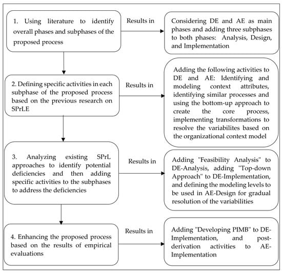
Figure 1.
The research methodology used to build the SPrLE process.
As SPrLE is a specific version of SPLE, we decided to include the three subphases explained earlier into the DE and AE phases of our proposed process. The proposed process is shown in Figure 2. As shown in Figure 2, returning from each subphase to the previous one(s) is possible, depicted in Figure 2 by feedback loops. Moreover, we can return from each subphase of AE to DE for applying changes to the models; this makes it possible to apply changes to the SPrL while constructing or using it.
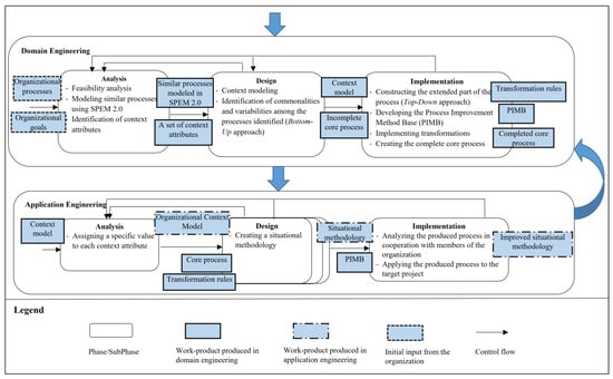
Figure 2.
Proposed process for SPrLE.
The activities performed in each subphase were defined in such a way as to tackle the deficiencies detected in previous approaches, as explained throughout the rest of this section.
The subphases of DE are performed as follows:
- Analysis: This subphase is focused on specifying the domain scope by identifying a subset of existing processes and a set of attributes to describe different project situations. However, we first need to analyze the current situation of the target organization to examine whether the SPrL approach is suitable for its specific needs (Feasibility analysis). If the SPrL approach is suitable for the organization, the current processes and organizational goals should first be identified to then be used for identifying the variabilities and context attributes. To this end, the processes currently used in the organization are fed to this subphase to be modeled in Software & System Process Engineering Metamodel (SPEM) 2.0 notation [47]. Organizational goals are also used here to help identify the context attributes that are important to the organization. The processes (modeled in SPEM 2.0) and a set of context attributes are the outputs of the analysis subphase.
- Design: The aim of this subphase is to build an initial version of the SPrL by identifying variabilities among existing processes; this activity is commonly performed in SPrL approaches (e.g., [10,12]). To this end, the outputs of the analysis subphase are fed to the design phase as input models. Context attributes are modeled by instantiating the context metamodel defined for this purpose. The similarities and variabilities among existing processes are also identified via the bottom-up approach; the output of this approach is an incomplete core process (also referred to as the reference architecture). The context model and the initial core process are the outputs of the design subphase.
- Implementation: This subphase is mainly focused on the following: improving the initial core process, building the required foundations for improving the processes after instantiation (post-derivation enhancement), and managing the complexity of process instantiation by providing a certain degree of automation. To this end, the outputs of the design subphase are fed to the implementation subphase as input models. During implementation, the top-down approach is applied to produce a metaprocess that includes all the variabilities identified in the target domain; the initial core process is then completed by enriching it with the results of the top-down approach. Transformations are also produced in this subphase, to be used in AE for automatic derivation of processes from the SPrL. As the process generated in AE may not satisfy all organizational/project needs (resulting in delta requirements), a process improvement method base (PIMB) is also produced; the PIMB contains process elements extracted from other processes, such as XP [48] and DSDM [49], which can be added to the generated process to address the delta requirements.
The subphases of AE are performed as follows:
- Analysis: The aim of this subphase is to specify the context in which a specific process needs to be built; these attributes are like requirements specific to a product in SPLE. To this end, context attributes are given specific values based on the situation at hand, and the organizational context model is produced.
- Design: This subphase is focused on producing a specific process while managing the configuration complexity by gradually resolving variabilities; the modeling levels comprising our proposed modeling framework are used in this subphase for gradual resolution of the variabilities. The organizational context model, core process and transformation rules are fed to the design subphase as input models. During design, the variabilities defined in the core process are gradually resolved by executing the pre-defined transformations in a multi-level fashion (based on the values of context attributes). The bespoke methodology thus generated is the output of the design subphase.
- Implementation: The aim of this subphase is to improve the constructed process by satisfying the remaining organizational/project needs (post-derivation enhancement); the need to conduct this activity has been identified throughout evaluating the proposed approach via a case study. The bespoke methodology is fed to the implementation subphase as the input model. The methodology is first analyzed, and if delta requirements are identified, the PIMB is used to address the shortcomings. The enhanced methodology is then applied to the target project.
The framework and the process are defined so that the proposed approach addresses the shortcomings observed in previous model-driven SPrLE approaches. To be specific, the four activities that we had identified as the main areas requiring improvement are properly addressed, as explained below:
- Feasibility analysis: The feasibility of using an SPrL approach for the organization is examined during DE by a set of requirements specifically defined for this purpose [13].
- Enhancing the core process: During DE, the top-down approach is applied to produce a metaprocess for the target domain. The core process created by analyzing existing processes (via the bottom-up approach) is combined with the metaprocess, resulting in an enhanced core process.
- Managing configuration complexity: During AE, configuration complexity is managed by the following: (1) providing semi-automation in resolving the variabilities, and (2) support for staged configuration by providing multi-level resolution of variabilities.
- Post-derivation enhancement: During the implementation subphase in AE, the process instantiated from the SPrL is analyzed to identify the remaining/delta requirements; the PIMB is then used to address the delta requirements.
A more thorough analysis of how the proposed approach compares to previous approaches with regard to supporting the above activities will be provided in Section 4.3.
3.1. Domain Engineering
The SPrL is built during DE’s three subphases. The subphases are explained in the following subsections.
3.1.1. Analysis
The following activities are performed in this subphase:
- Feasibility Analysis: Organizations should first examine whether the SPrL approach is suitable for their specific needs. In [13], we have identified a comprehensive set of requirements for adopting the SPrL approach. These requirements have been presented in the form of a questionnaire, which has been designed for determining the suitability of organizations for creating SPrLs; the questionnaire has been explained in [13]. Organizations that intend to develop an SPrL can consider this questionnaire as a suitability filter. The more an organization satisfies the requirements, the more justified it is to adopt the SPrL approach. As pointed out in [13], the level of importance of the requirements may not be the same in different contexts. Furthermore, it is required that a threshold be determined when applying the requirements to a specific context; this threshold is the minimum score that should be satisfied by the organization in order to be suitable for creating the SPrL. An example of the application of requirements for feasibility analysis has been provided in Appendix A.
- Modeling similar processes using SPEM 2.0: Of the requirements defined in [13], two are related to all the (potential) processes that can be instantiated from the core process (the process line portfolio): Structural similarity, and Process type. These two requirements are used for identifying the software processes in an organization that will be used for constructing the core process of the SPrL. Structural similarity refers to the degree of similarity in the structure of processes selected for creating the core process; there is no rigid threshold, but the degree of variabilities defined in the core process should be justifiable. Process type refers to the type of processes that will be part of the SPrL (such as agile or plan-driven). As the identified processes may have been modeled in different notations (or not documented at all), all of them should first be modeled/re-modeled in SPEM 2.0 [47] in order to unify their representations and thereby facilitate the identification of their commonalities and variabilities. SPEM 2.0 has been selected because it is the OMG standard for software process modeling.
- Identification of context attributes: Context attributes (also referred to as situational factors [50]) are used for describing the situation in which a specific process should be built. These attributes are the specific characteristics of the organization (e.g., maturity level), or the project at hand (e.g., degree of risk), or the individuals involved in the project (e.g., skill and knowledge). There are many research works on specifying situational factors (e.g., [51,52,53,54]). These works can also be used as sources for identifying context attributes; however, the tacit knowledge of subject matter experts should also be explored to refine these context attributes.
3.1.2. Design
The following activities are performed in this subphase:
- Context Modeling: The context attributes identified in the analysis subphase are fed to this activity as input. These context attributes are modeled using the metamodel shown in Figure 3. The metamodel has been implemented in Medini-QVT [55]; in this tool, metamodels are defined as Ecore metamodels and transformations are implemented as QVT rules. An example of modeling context attributes in this tool has been shown in Appendix B.
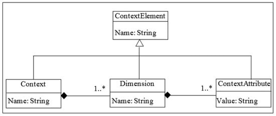 Figure 3. Context Metamodel.
 - Identification of commonalities and variabilities among the processes identified (Bottom-Up approach): The bottom-up approach can result in an inappropriate core process, as existing processes may not be ideal. The top-down approach is also error-prone, as it attempts to define the commonalities and variabilities in a particular domain from scratch. We have therefore decided to combine the two approaches. The bottom-up approach is used in the design subphase of DE for building an initial core process, and the top-down approach is used for improving the quality of the produced core process in the implementation subphase of DE. Separating the bottom-up and top-down approaches has specific benefits, including the following:
- −
- The organization can use an existing metaprocess to improve the core process instead of expending time and effort on improving existing processes. For example, the Scrum metaprocess [56] can be used in organizations that use different versions of Scrum.
- −
- The organization may not have enough knowledge to improve existing processes. Creating the metaprocess through the application of the top-down approach by experts can address this issue.
- −
- The metaprocess can be used to train organizational staff, and also to document the software processes currently used in the organization.
Variability management is a key activity in SPrLEs and is used in both bottom-up and top-down approaches; hence, we will first explain our proposed variability management approach, and will then elaborate on the proposed bottom-up approach.
Variability Management in the Proposed Approach
Several approaches have been proposed for variability management in SPrLE approaches. In [57], a criteria-based evaluation has been conucted on four such variability management methods: SPEM, vSPEM [58], Feature Model [59], and OVM [59]. The results show that none of the approaches satisfies the requirements identified in [57] for adoption in the industry. Furthermore, the authors have concluded that SPEM 2.0 is the best approach, since it allows the specification of the process and its variabilities using only one notation and one tool (Eclipse Process Framework Composer—EPFC). On the other hand, SPEM’s variability mechanisms are rather limited; for instance, it has no mechanisms for representing the relationships and constraints of variabilities. Even vSPEM [58], an extended version of SPEM 2.0, lacks mechanisms for defining multilevel variabilities.
To address the above problems, we modeled the software process, along with its variation points, via the metamodel shown in Figure 4. The problems have been resolved as follows: the left part of the metamodel is inspired by SPEM 2.0, since it has been recognized as an effective metamodel (even considered by some researchers as the best [57]); the semantics of some of the concepts defined in the ProcessStructure and MethodContent packages of SPEM 2.0 have been changed to fit our requirements. The right part of the metamodel shows new elements that focus on software process variability. These additions have been defined to overcome the limitations of SPEM’s variability mechanisms, and include the following elements:
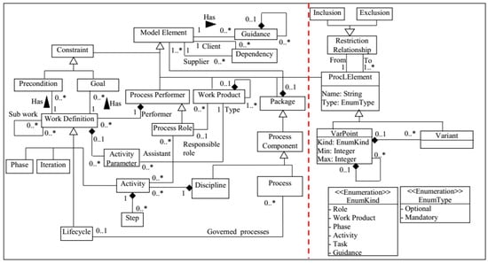
Figure 4.
The variability metamodel used in the proposed SPrLE approach.
- ProcLElement: This abstract class represents SPrL elements and has two subclasses: Varpoint, and Variant. As shown in Figure 4, ProcLElement is a subclass of the Model Element class; therefore, each instance of ProcLElement subclasses can be connected to instances of the Model Element subclasses via the Dependency class.
- VarPoint: Each variation point in the core process is an instance of this class; it can be of different types and granularities, namely the following: Phase, Activity, Task, Role, Work Product, and Guidance. Each variation point can be either Mandatory or Optional. It can include one or more variants that show possible alternatives for resolving the variability [1,60]. Furthermore, multi-level variabilities can be defined via the composition relationship drawn from the VarPoint class to itself, so that each variation point can include one or more other variation points. We have replaced or, xor, and and relations with UML-style multiplicities. Multiplicities consist of two integers: a lower bound and an upper bound, which are specified by two attributes in the VarPoint class: Min and Max.
- Variant: The variants related to variation points are instances of this class, and can be either Mandatory or Optional.
- Restriction Relationship: The relationships and constraints of variabilities can be represented via the Restriction Relationship class. Both variation points and variants can affect other parts of the process structure, as a variation point may exclude another one. These dependencies are represented by the Inclusion and Exclusion classes, which are subclasses of the abstract class Restriction Relationship.
The variability metamodel has been defined in Medini QVT; an example of the variability modeling performed in the tool has been presented in Appendix C.
Bottom-Up Approach
The Software Product Line domain offers many approaches for migrating existing systems to SPLs (e.g., [61,62]); these approaches analyze existing systems to identify code similarities and variabilities and then migrate a family of legacy software products to an SPL. Similarly, as the core process is an integral part of an SPrL, it is required that the similarities and variabilities of a set of process variants be analyzed to construct the core process. However, existing SPrLE approaches lack a precise method for this purpose. We therefore propose a multistep bottom-up approach for building an initial core process. Although the overall idea is similar to what has already been used in Software Product Lines, our approach focuses on identifying the similarities and variabilities of processes (rather than code), which makes the context quite different. Our proposed approach is currently performed manually, but it has the potential to be automated via model transformation tools. An example of applying the proposed bottom-up approach is shown in Figure 5, depicting how the commonalities and variabilities of three hypothetical processes (X, Y, and Z) are identified. The notation used in Figure 5 (shown in the legend) will be used throughout this paper for representing the commonalities and variabilities of processes. The steps of the proposed bottom-up approach are as follows:
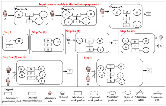
Figure 5.
Example of applying the bottom-up approach on three hypothetical processes.
- Elements that are common to the processes are identified. These elements are of these types: Phase, Activity, Task, Role, Input/Output, Work Product, Guidance, and Dependency relationships. A process element is common to a set of processes if its name and description is identical in all of them. A dependency relationship is included in the core process if the elements on both sides have already been identified as common elements. An example of the output of this step is shown in Figure 5 (Step 1).
- Variation points and related variants are identified through the following substages by analyzing each of the phases, activities, and task elements that are not already included in the core process (we will call it e1):
- a.
- If the predecessor (e1-pre) or the successor (e1-succ) of e1 is already identified as a common element, two outcomes are possible: (1) an optional variation point is added to the core process, either after e1-pre or before e1-succ, and e1 is added as its optional variant; an example of the output of this step is shown in Figure 5 (Step 2-a (1)). (2) If a variation point after e1-pre or before e1-succ is already defined, no variation point is added to the process model, and e1 is just added to the core process as an optional variant under the previously defined variation point.
- b.
- If the predecessor (e1-pre) and successor (e1-succ) of e1 are not common elements, an optional variation point is added to the core process after or before the variation point related to e1-pre or e1-succ, respectively, and e1 is added as its optional variant.
- c.
- If at least one element of each process is added under a common variation point, the variation point is converted to a mandatory variation point.
- d.
- If no predecessor/successor elements exist before/after e1, an optional variation point is added to the core process under the process element with the higher granularity, and e1 is added as its optional variant. For example, the variation point related to a task is added under the related activity.
If any elements of types phase or activity are added to the core process in this step, steps 1 and 2 are repeated for them in order to identify their common and variable internal elements. - For each role, work product, and guidance that is not already included in the core process (we will call it e2), its variation points and variants are specified through these substages:
- a.
- If the phase/activity/task related to e2 is already added to the core process as a common element, three outcomes are possible: (1) An optional variation point is added to the core process and a dependency is established between the phase/activity/task and the variation point, and e2 is added as its optional variant; an example of the output of this step is shown in Figure 5 (Step 3-a (1)). (2) If another element of the process under investigation with the same type as e2 has already been added as a variant under a variation point, e2 is only added to the core process as an optional variant under the variation point, and the variation point is converted to Alternative OR, which is specified in our approach by assigning 1 to Min, and n (the number of variants) to Max; an example of the output of this step is shown in Figure 5 (Step 3-a (2)). (3) If another element of another process with the same type as e2 has already been added as a variant under a variation point, e2 is only added to the core process as an optional variant under the variation point, and the variation point is converted to Alternative XOR, which is specified in our approach by assigning 1 to Min and 1 to Max; an example of the output of this step is shown in Figure 5 (Step 3-a (3)).
- b.
- If the phase/activity/task related to e2 is not already specified as a common element, three outcomes, similar to those explained in the previous step, are possible. However, a dependency is established between the variation point related to the phase/activity/task and the variation point added to the core process.
- c.
- If at least one element of each process is added under a common variation point, the variation point is converted to a mandatory variation point. As the result of this step, the variation points related to the roles and techniques shown in Figure 5 are converted to mandatory (Step 3-c). Due to space limitations, the variation points are not shown in Figure 5, and variants are directly connected to the related process elements.
- For each dependency relationship that is not already added to the core process, the elements or variation points related to the elements on both sides of the dependency are found in the core process, and a dependency relationship is added between them; an example of the output of this step is shown in Figure 5 (Step 4).
3.1.3. Implementation
The following activities are performed in this subphase:
- Constructing the extended part of the core process (Top-Down approach): In the bottom-up approach, the initial core process is created by analyzing existing processes. To address the problems in existing processes, and thereby enhance the initial core process constructed, we use the top-down approach to create a metaprocess that includes all the variabilities in the target domain. Existing process frameworks, such as DAD [63], can also be used for this purpose. The top-down approach has already been used for constructing SPrLs (e.g., in [21,23]); however, it has been used in previous research to identify the variabilities in standard processes that can be instantiated across multiple organizations, whereas in our approach, the top-down approach has been used for enhancing the SPrL being created in a target organization. Furthermore, the bottom-up approach has never been used for analyzing the existing processes of an organization.An organization interested in implementing an SPrL can create the metaprocess by identifying the variabilities in a process framework; the selection of the framework depends on the type of processes being used in the organization. As Scrum is the most widely used agile framework, we have defined the Scrum metaprocess [56] through the top-down approach as an example. An example of the variabilities identified in the Scrum metaprocess has been provided in Appendix D.
- Developing the Process Improvement Method Base (PIMB): The constructed process may not satisfy all organizational/project needs (remaining requirements/delta requirements). To address this problem, a method base (PIMB) is built for storing additional core assets. PIMB’s metamodel is shown in Figure 6. This metamodel is an extended version of the left-hand section of the variability metamodel shown in Figure 4; two relationships have been added: one between Model Element and Context Attribute, and the other between Guidance and Context Attribute. The relationships between context attributes and process elements are also stored in PIMB. If the instantiated process cannot satisfy all the needs, context attributes are given specific values and are then fed to the transformations; by executing the transformations, suitable process elements are automatically extracted from PIMB. The metamodel has been defined in Medini QVT; the method base has been built by instantiating the metamodel and enriching it with process elements from DSDM and XP. However, the method base can be complemented by other process elements as well. The process elements so far defined in the method base are presented in Appendix E, and an example of how PIMB can be used for satisfying the delta requirements is provided in [64].
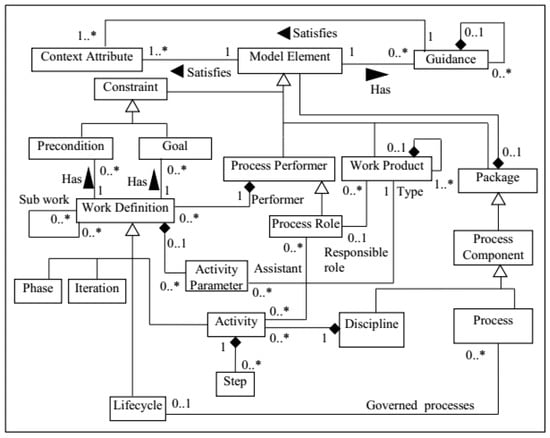 Figure 6. Metamodel of PIMB.
 - Implementing transformations: Transformations are used for automatic derivation of a process from the SPrL. Transformations are implemented in a tool using a model transformation language, such as QVT [55]. Medini QVT has been used for implementing transformations in our approach; however, organizations can use other tools or languages for this purpose. An example of the implemented transformations has been provided in Appendix F. Due to space limitations, we will not provide the detailed descriptions of other transformations implemented for resolving the variabilities of the Scrum metaprocess. The complete set of transformations is available on Mendeley Data [64].
- Creating the complete core process: The models created by the bottom-up and top-down approaches are merged to obtain the final core process. This stage is currently performed manually. If the required transformations are implemented, the two input models can be automatically merged to produce the completed core process.
To provide an overall overview, examples of the work products of DE subphases are provided in Appendix G.
3.2. Application Engineering
The SPrL is instantiated during AE’s three subphases to yield bespoke processes for specific project situations. The subphases are explained in the following subsections.
3.2.1. Analysis
The context model created in DE is fed to this subphase as input, and the values of context attributes are set by the process engineer according to the project situation at hand. Consequently, an Organizational Context Model (OCM) is produced. An example of an OCM implemented in the tool has been presented in Appendix H.
3.2.2. Design
The organizational context model, core process model, and transformations are fed to this subphase, and a specific process is automatically created by applying the transformations. The target process is gradually created by using multilevel modeling, which is an essential MDD feature; the process model is gradually refined from a fully abstract specification to a fully concrete one. Although the target process is automatically created, the output of each level can be polished, as needed, at the process engineer’s discretion. As shown in Figure 4, specific constraints are defined in the core process, including Multiplicity, and Restriction Relationships. These constraints should be considered in variability resolution. As variability resolution is automatically performed in our approach, checking these constraints is performed through the following transformations:
- Inclusion: If a variant selected at a specific level has “inclusion” relationship with another variant, that variant is added to the process under construction.
- Exclusion: If a variant selected at a specific level has “exclusion” relationship with another variation-point/variant, that variation-point/variant is removed from the process under construction.
- Multiplicity: If there is a variation point with (min, max) = (1,1), selecting one of the variants of the variant group results in removing the variation point from the process under construction.
Modeling levels can be differentiated according to different concepts; we propose the framework shown in Figure 7 for defining the modeling levels used in the AE phase. In this framework, two dimensions are used for distinguishing the modeling levels: Granularity level of the method fragments, and Abstraction level of the context attributes; these dimensions can be extended as required. Each dimension specifies an ordered set of simple or composite modeling levels. A composite level includes an abstract dimension and therefore, an ordered set of nested levels.

Figure 7.
Proposed framework for defining the modeling levels.
In the “Granularity level of method fragments” dimension, a variation point is resolved based on the granularity level of its type. In other words, variation points with a higher granularity, such as the ones associated with phases or activities, are resolved first (at higher levels of modeling); whereas variation points with a lower granularity, such as those associated with tasks, roles, and work products, are resolved at lower levels. This solution can have several benefits; e.g., reusability is enhanced because higher-level models are independent from lower-level method fragments, and are hence more readily reusable due to their relative abstractness. We have defined three modeling levels using this dimension: Methodology-Fragments-Independent Level, Technique-Independent Level, and Technique-Specific Level. At the fragment-independent level, variation points at the granularity levels of Phase or Activity are resolved; at the technique-independent level, variation points at the granularity levels of Task, Work Product, and Role are resolved; at the technique-specific level, variation points at the granularity level of Guidance are resolved.
In the “Abstraction level of context attributes” dimension, situational factors are classified based on their abstraction levels; there are three types of situational factors: Organizational, Environmental, and Project; this classification has been adapted from [50,51,65,66]. There are three modeling levels based on this classification: Organizational Level, Environmental Level, and Project Level. At the organizational level, all the variation points dependent on the values of organizational factors are resolved; organizational factors are characteristics of the organization (or unit thereof) responsible for developing the system, such as “Personnel experience”. The output of this level is an SPrL specific to the organization (or unit). The produced SPrL can be used for different projects and customers. At the environmental level, all the variation points dependent on the values of environmental factors are resolved; environmental factors are characteristics of the environment in which the system will be operated, such as “End-user experience”. The output of this level is an SPrL specific to a customer of the organization; the produced SPrL can be used for different projects of the customer. At the project level, all the variation points dependent on the values of project factors are resolved; project factors are characteristics of the system under development, such as “Degree of risk”. The output of this level is a specific process, without any unresolved variation points, for the project.
For gaining the full benefits of these two dimensions in our proposed approach, “Abstraction level of context attributes” is used for defining the outer modeling levels, and “Granularity level of method fragments” is used for defining the inner levels, as shown in Figure 8. Based on these modeling levels, variation points are resolved in the following order: at level 1.1, variation points that are dependent on organizational factors and have a granularity of Phase or Activity are resolved; at level 1.2, variation points that are dependent on organizational factors and have a granularity of Task, Role, or Work product are resolved; and at level 1.3, variation points that are dependent on organizational factors and have a granularity of Guidance are resolved. Resolution at levels two and three is performed in a similar fashion, but for variation points that are dependent on Environmental factors and Project factors, respectively. If a variation point is dependent on a combination of factors, the resolution is performed at the lowest abstraction level corresponding to the factors. For example, if a variation point is dependent on a combination of organizational and environmental factors, its resolution is performed at level two. An example of resolving the variabilities throughout the modeling levels has been provided in Appendix I.
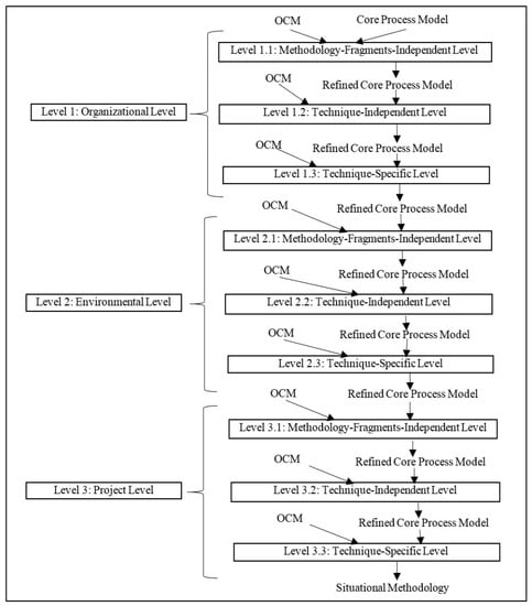
Figure 8.
Modeling levels defined in the design subphase.
3.2.3. Implementation
The activities performed in this subphase are as follows:
- Analyzing the produced process in cooperation with members of the organization: The process produced in the previous phase is analyzed to identify the organizational/project needs that have not been addressed. If such needs exist, transformations are applied to PIMB to extract suitable process elements for addressing those needs.
- Applying the produced process to the target project: The produced process is enacted in the real world, and the results of its application may call for further iterations of DE and AE.
To provide an overall overview, examples of the work products of AE subphases are provided in Appendix J.
4. Evaluation
The proposed approach has been evaluated through a case study, an experiment, and a comparison performed between the proposed approach and other SPrLE approaches.
4.1. Case Study
In order to validate the proposed approach as to applicability and efficacy, an industrial case study was designed with the following research questions:
RQ1.
What are the challenges of using the proposed approach for developing a process line?
RQ2.
Can the specific processes produced from the SPrL improve the processes currently used in the organization?
The intention of the first RQ is to evaluate the applicability of the proposed approach in real situations; therefore, we have focused on identifying the challenges that an organization might face during the use of our approach. Thus, the activities defined in the proposed approach to address the shortcomings observed in previous approaches have been evaluated as to their applicability. The intention of the second RQ is to evaluate whether the top-down approach, as used in our proposed process, can indeed result in improvements to the processes currently used in the organization.
We sought a case that was suitable for creating SPrLs based on the set of requirements defined in [13], and the recommendations proposed in [67]. Based on [67] (p. 48), case study selection in software engineering research is usually performed based on the availability of the case. Furthermore, adding or removing cases due to practical constraints and objectives of the research may occur as the study progresses [67] (p. 64). We first selected two companies to conduct feasibility analysis based on the requirements presented in [13]. Then, we decided to add two more companies since one of the first two companies used only one version of Scrum. All of the four candidate companies were selected based on their existing relationships with the authors of this paper. We also sought cases where people with enough knowledge about the processes being used in the organization had enough time to collaborate with us during the execution of the case study. In [13], we have identified a comprehensive set of requirements for adopting the SPrL approach. These requirements have been presented in the form of a questionnaire, which has been designed for determining the suitability of candidate companies for creating SPrLs in the case study. The more a company satisfies the requirements, the more justified it is to adopt the SPrL approach. The questionnaire has been presented in Appendix K.
The study was conducted in a medium-sized, Iranian software development company, which we will call ‘A’ (the real name has been made anonymous). Company A, which has 120 employees, is made up of four units (A1, A2, A3, A4), and its organizational software process is based on Scrum. Various products are developed at this company, including systems software, web applications, databases, web designs, graphics designs, multimedia software, mobile applications, games, and desktop applications. The Scrum process implemented in each unit was not documented. In order to identify how Scrum was used in the units, one in-progress project was selected from each unit. Brief descriptions of these projects are presented in Table 1. The size of each development team was between 2 to 9 people.

Table 1.
Projects selected in A.
Since there was no documented information about the processes used in the projects, the subject sampling strategy was to interview a sample of the people involved in the projects who had enough information about the processes used. In total, four people were interviewed, who played “Project Manager” or “Product Owner” roles in the projects. Three semi-structured one-hour interview sessions were held with each subject. The interview instruments are provided in Appendix L. These instruments were intended to focus the interviewees’ attention on the areas of discussion. The instruments were adapted as the interviews progressed to gain further information about the process used in the organization and the problems occurring during its execution. In addition to the notes taken during the interviews, sound recordings were produced to provide transcripts for the analysis process. The answers given to the research questions are provided in the following subsections.
4.1.1. RQ1. What are the Challenges of Using the Proposed Approach for Developing a Process Line?
In this study, we investigated all the activities mentioned in Scrum, from planning to development. However, for sake of brevity, we will only focus on one activity herein, namely “Sprint Execution”. To answer the research questions (RQ1 and RQ2), we will first explain the activities performed for creating the SPrL in the following subsections.
Domain Engineering
In this section, the activities performed for creating an SPrL for A are explained (Sections A, B and C).
- A.
- Analysis
The following tasks were performed:
- Feasibility analysis: The suitability-filter questionnaire was filled out by four companies, of which A was then identified as a suitable venue for creating an SPrL. The questionnaire has been provided in Appendix K.
- Modeling similar processes in SPEM: Interview sessions were held to elicit the different versions of the Scrum process used in A. These processes were then modeled with the tool.
- Identification of context attributes: In [51], a reference framework has been proposed for situational factors that affect software processes; we used this framework to identify the situational factors relevant to agile methodologies. These factors were then refined and completed based on other resources. The finalized list of situational factors is shown in Table 2, along with the additional resources that were used for refining or extending them. The third column in Table 2 depicts the range of possible values for each factor. Attributes under Personnel and Organization are considered as organizational factors; the attribute under Operation is considered as an environmental factor; attributes under Requirements, Application, and Business (except for the Opportunities attribute) are classified as project factors; and the Opportunities attribute, by definition, is an organizational factor.
 Table 2. Situational factors (context attributes) relevant to agile methodologies.
- B.
- Design
The following tasks were performed:
- Context modeling: The situational factors shown in Table 2 were modeled in the tool.
- Identification of commonalities and variabilities (Bottom-up approach): The commonalities and variabilities among the processes being executed in A were identified by applying the bottom-up approach; details have been provided in [64]. For sake of brevity, only “Sprint Execution” is presented herein (Figure 9).
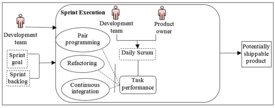 Figure 9. “Sprint Execution” in A.
- C.
- Implementation
The following tasks were performed:
- Constructing the extended part of the core process (Top-Down approach): The “Sprint Execution” variabilities that were defined in the Scrum metaprocess have already been shown in Figure A7 in Appendix I.
- Developing PIMB (method base): The PIMB, implemented in Medini-QVT, is provided in Appendix E.
- Creating the complete core process: The final SPrL was created by combining the models created by the bottom-up and top-down approaches. An overview of this SPrL is shown in Figure 10. The details and variabilities of “Sprint Execution” in the Scrum metaprocess (Figure A7 in Appendix I) were more comprehensive than the processes being used in A (Figure 9). Therefore, the combined result was similar to Figure A7.
 Figure 10. Overview of the proposed SPrL for A.
 - Implementing transformations: A set of transformations were implemented in the tool for resolving the variabilities identified in the core process. The transformations have been provided in [64].
Application Engineering
In this section, the activities performed for instantiating processes from the SPrL for projects in A are explained (Sections A, B, and C).
- A.
- Analysis
The values of context attributes in projects A.1 to A.4 were determined. For the sake of brevity, only the values of context attributes for project A.2 are presented in Appendix M. The values for other projects are provided in [64].
- B.
- Design
The variation points defined in the SPrL were gradually resolved by executing the transformations based on the values of context attributes. In the SPrL produced, there is just one phase variation point, namely “Maintenance with Kanban”. By resolving this variability, several process elements and their associated variabilities were added. The transformation implemented for this purpose is shown in Appendix N. Examples of multilevel resolution of variabilities implemented in the tool are provided in [64]. The processes currently used in A, processes produced by instantiating the SPrL, and transformations implemented in the tool have also been provided in [64].
- C.
- Implementation
The tasks were performed as follows:
- Analyzing the produced process in cooperation with members of the organization: The subjects of A confirmed that all organizational/project needs could potentially be satisfied by the processes instantiated from the SPrL, except for two problems related to the A.4 project. One problem was related to intra-team knowledge sharing, and the other was related to the capabilities of team members in writing high-quality code. Transformations were therefore applied to PIMB, and the following guidances were extracted: “Moving people around”, “Preparing documents of project status”, and “Training team members on code quality by a coach”.
- Applying the produced process to a real-world project: Parts of the process produced for project A.2 were applied in one sprint. The results are presented in Section 4.1.2.
Challenges Identified during the Application of the Proposed Approach for Creating the SPrL
The challenges that we faced when applying the proposed approach are as follows:
- Identifying commonalities and variabilities among existing processes in case A was time-consuming, mainly because their processes were not documented.
- Presenting the variabilities of the Scrum metaprocess implemented in the tool to subjects was difficult. To facilitate the adoption of SPrLs in organizations, a high level of user friendliness is needed in the user interface of the tool.
- Assigning values to situational factors was challenging since subjects had different opinions about them. To address this issue, we recommend that organizations provide concrete examples on how to assign a specific value to each situational factor based on organizational context and project characteristics.
- Using the tool for executing transformations was difficult for the subjects because of its low-level user interface. Implementing a graphical user interface would therefore improve the adoption of SPrLs in organizations.
4.1.2. RQ2. Can the Specific Processes Produced from the SPrL Improve the Processes Currently Used in the Organization?
To answer this question, the subjects involved in project A.2 applied specific parts of the instantiated process in their upcoming sprint. A questionnaire was used to acquire feedback on the impact of applying the proposed process, which is provided in Appendix O. We asked the respondents to state their opinion on whether the process elements applied improved the process currently used; a list of the problem-solution pairs is provided in Appendix P. Figure 11 shows a summary of the responses given by six subjects to the questions. Almost all of the respondents agreed that the process elements applied had had a positive effect on improving the process currently used in project A.2.
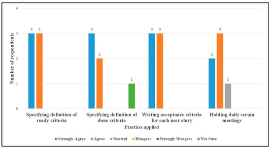
Figure 11.
Summary of responses in project A.2.
In addition to the questions about the process elements applied, we also designed questionnaires for identifying the potential effects of some of the proposed process elements on improving the processes being used in projects A.1, A.3, and A.4. The questionnaires are provided in [64]. Analyzing the responses given by nine subjects to these questions indicated that the percentage of positive responses to the proposed practices was above 50%.
4.1.3. Discussion on Case Study Results
The main result of this study was creating an SPrL for company A that could be used for building specific processes. Although certain challenges were faced in applying the approach (RQ1), it had several benefits from the subjects’ point of view: documenting the processes being used in the company and identifying their deficiencies, gaining knowledge about the factors influencing the processes, and producing future processes in less time and with less effort. The results of the improvements showed that the proposed approach can indeed address the shortcomings of existing processes by infusing best practices through the top-down approach and also by using the PIMB method base (RQ2).
There are several threats to the validity of this case study, including the following:
- Internal validity: A potential threat to internal validity is subject fatigue; this was handled by planning interviews in multiple one-hour sessions. Another threat to internal validity is misinterpretations in the interviews; to mitigate this threat, in addition to the notes taken during interviews, sound recordings were produced to later be transcribed as part of analysis. The results of each interview session were also reported back to the subjects via email and face-to-face conversation (Member checking).
- Construct validity: A potential threat to construct validity is subject selection. Random subject selection was not possible, as we needed subjects with adequate knowledge about the processes used. However, viewpoints of the different roles involved were considered throughout the case study, as well as in the questionnaire designed for obtaining feedback about the proposed practices (Theory triangulation). Furthermore, a case study protocol was defined at the beginning of the study and was updated continuously afterwards (Audit trail).
- Conclusion validity: One potential threat to conclusion validity is the reliability of the study results. Reviewing the procedures selected for data collection and analysis by an expert (the second author), member checking, and theory triangulation helped mitigate this risk.
- External validity: An inherent problem of case studies is external validity. To mitigate this risk, we applied the approach on a real case. However, the study has been conducted in a company that based its software processes on Scrum; therefore, we cannot generalize the results to companies using other types of processes.
4.2. Experiment
The challenges of applying the proposed approach and its efficacy were scrutinized through the case study. However, the fundamental question still remained: how does process instantiation by the proposed approach (AE phase) compare to the ad hoc, manual approach that is commonly used to construct bespoke processes? An experiment was designed and executed to answer this question by assessing two quality attributes: usefulness and ease of use (Table 3). These attributes have previously been used for evaluating model-driven SME approaches [77]. The subjective and objective measures used in this experiment are shown in Table 3. As most usability studies use questionnaires to evaluate satisfaction [78], we designed a two-part questionnaire to gather the subjective data. The first part was designed to evaluate the users’ perceived usefulness and ease of use; this section was prepared based on the questionnaires defined by TAM [79], as it is the most widely used model for evaluating usefulness and ease of use based on subjective data [80]. The second part was designed to measure the completeness of the process produced (as a measure of its effectiveness). The objective measure was the time expended on defining the target process (completion time), which is considered as a measure of efficiency. The guidelines recommended by [81] were followed in designing the experiment. Before finalizing the design, a pilot run was performed with two subjects; these subjects were not involved in the main experiment. The details of the experiment and its results are explained in the following subsections.

Table 3.
Measures used in the experiment.
4.2.1. Definition, Planning, and Execution
The experiment’s goal was formulated as follows: Analyze the proposed approach as to usefulness and ease of use from the point of view of process engineers within the context of academia and industry. Usefulness is focused on evaluating whether the proposed approach helps build a specific process that satisfies all project/organization needs and adequately manages configuration complexity; therefore, through this question, we intend to verify that the solutions proposed by our approach do indeed address the shortcomings observed in previous approaches, including the following: Enhancing the core process, Managing configuration complexity, and Post-derivation enhancement. Ease of use is specifically focused on evaluating the ease of use of the proposed approach for constructing the SPrL and instantiating it to produce a specific process.
To achieve this goal, research questions were defined as follows:
RQ3.
What is the users’ perceived usefulness of the proposed approach?
RQ4.
What is the users’ perceived ease of use of the proposed approach?
RQ5.
To what extent does the proposed approach enhance efficiency?
RQ6.
To what extent does the proposed approach enhance effectiveness?
In order to compare the efficiency and ease of use of the proposed approach with the manual ad hoc alternative, we need subjects with knowledge on Scrum, model-driven engineering, and process engineering so that they can build an instance of Scrum by using their own tacit knowledge and then compare it with the results of using the proposed approach. Therefore, a total of 32 Computer Science graduates (MS or PhD) were invited to participate in the experiment, of which 14 subjects agreed to collaborate: eight of the subjects were professional developers, one subject was a post-doc student, and five were PhD students. These subjects were former members (12 subjects) or current members (2 subjects) of the Methodology Engineering (ME) Laboratory at the Department of Computer Engineering, Sharif University of Technology; we limited the subjects to ME-Lab members since it is the only laboratory in Iran that focuses on process engineering. Eleven subjects had already used Scrum in their past projects and three subjects had participated in process engineering courses covering Scrum. It should be mentioned that all of the subjects were either studying PhD abroad (12 subjects) or were involved in other industrial/research projects when this research was being conducted; therefore, none of them were familiar with the research or the tool. The “Sprint Execution” activity of Scrum and a hypothetical project situation were considered as experiment objects. The demographic data of the subjects and the description of the hypothetical situation are provided in Appendix Q and Appendix R, respectively.
One factor (SPrLE approach) with two treatments (Ad hoc and Proposed approach) was applied in the experiment. All the subjects applied both treatments, so this was a “Within-Subject” designed experiment. In the Ad hoc treatment (manual approach), subjects defined a Sprint Execution suitable for the hypothetical situation by using their own tacit knowledge. In the second treatment, subjects used the Medini QVT tool and the packages provided by the proposed approach (situational factors, transformations, and the Scrum metaprocess) for automatic resolution of the variabilities of the Scrum metaprocess to produce the target “Sprint Execution”; this was done by assigning values to the situational factors, and then executing the transformations. A training session was conducted for the subjects to ensure that they could work effectively with the tool. Since the subjects were geographically distributed, the experiment was executed online. The experiment’s design is illustrated in Figure 12. Independent and dependent variables of the experiment are presented in Table 4. Subjects used a timer to measure the time expended on creating the target process. At the end of each treatment, subjects submitted a snapshot of the resulting process along with the time it took to produce. After the execution of the experiment, subjects filled out a post-questionnaire, which is provided in Appendix S; the instruments used for executing the experiment are provided in Appendix T.

Figure 12.
Experiment setup.

Table 4.
Independent and dependent variables in the experiment.
To answer the research questions, subjective and objective data were analyzed as follows:
- Subjective data were of two types: quantitative data and qualitative data. To analyze the quantitative data, which were obtained from closed-ended questions, numerical values were assigned to the responses given to these questions (from 5 for “Strongly agree,” to 0 for “Not sure”). The minimum, maximum, and average values for each Likert item of the questionnaire were then calculated. Qualitative data were obtained from open-ended questions; responses to these questions were categorized in three groups: Problems and challenges, Benefits, and Suggestions for improving the approach.
- Objective data were obtained by measuring the time expended by the subjects in each treatment. The Wilcoxon signed-rank test was used to verify whether differences in time measurements were statistically significant.
4.2.2. Results
In this section, results of the experiment are explained through analyzing its four research questions.
RQ3. What Is the Users’ Perceived Usefulness of the Proposed Approach?
The distribution of the responses given to questions on perceived usefulness is shown in Figure 13. Analysis results are shown in Table 5. Most of the subjects answered “Strongly agree” or “Agree” to whether the proposed approach improved Accuracy and Performance (overall average: 4.21). This result was reinforced by the qualitative feedback; the answers given to the open-ended questions are provided in [64].
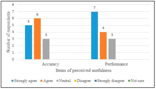
Figure 13.
Distribution of responses given to questions on perceived usefulness.

Table 5.
Analysis results on perceived usefulness.
RQ4. What Is the Users’ Perceived Ease of Use of the Proposed Approach?
The distribution of the responses given to questions on perceived ease of use is shown in Figure 14. Analysis results are shown in Table 6. All of the subjects answered “Strongly agree” or “Agree” to whether the proposed approach supported Complexity Management, and most subjects answered “Strongly agree” or “Agree” to questions on the proposed approach’s Understandability and Ease of Use (overall average: 4.19). This result was reinforced by the qualitative feedback.
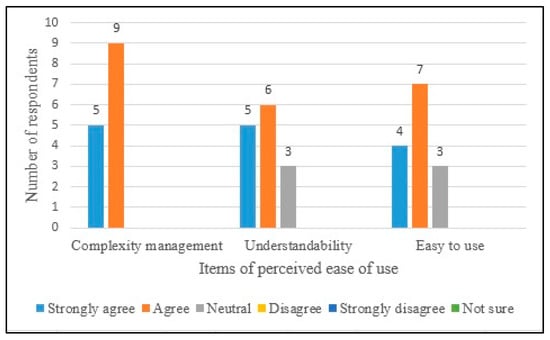
Figure 14.
Distribution of responses given to questions on perceived ease of use.

Table 6.
Analysis results on perceived ease of use.
RQ5. To What Extent Does the Proposed Approach Enhance Efficiency?
The subjects’ efficiencies are shown in Figure 15. The distribution of data in the box plots indicates that more than half of the subjects were more efficient in building an instance of Sprint Execution without using the SPrLE approach. The reason for this result was the high amount of time expended on assigning values to situational factors; the values assigned to situational factors for the hypothetical situation are provided in [64].
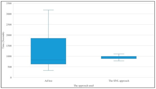
Figure 15.
Efficiency of subjects in the two treatments.
As shown in Figure 15, in the Ad hoc treatment, some of the subjects expended more time than others; however, in the second treatment, the times expended by different subjects were not significantly different. This indicates that the Ad hoc approach is relying, to a large extent, on expertise; whereas in the model-driven approach, the times expended are almost stable. Even though this stability is not always optimal, it is still interesting from a project management perspective.
The Wilcoxon signed-rank test was applied to verify whether differences in the times were statistically significant. This test was selected because the results of the Kolmogorov-Smirnov test (p = 0.06) indicated that a normal distribution could not be assumed. In the Wilcoxon test, p = 0.747 was obtained for an alpha level of 0.05. Since p > ∝, we could not reject H0. Thus, there was no significant difference in the times expended on the two treatments. However, the average time expended by the subjects in the second treatment (971.1 s) was lower than the average time expended in the first treatment (1229.7 s); this might show that using the proposed approach was generally more efficient than the alternative.
RQ6. To What Extent Does the Proposed Approach Enhance Effectiveness?
Figure 16 shows the result of executing the transformations in the tool (second treatment). To measure the effectiveness of the proposed approach, we compared the instances of “Sprint Execution” produced in the two treatments. Results showed that only 32.79% of the process elements shown in Figure 16 were identified by the subjects in the Ad hoc treatment. The details of this comparison are provided in Appendix U.
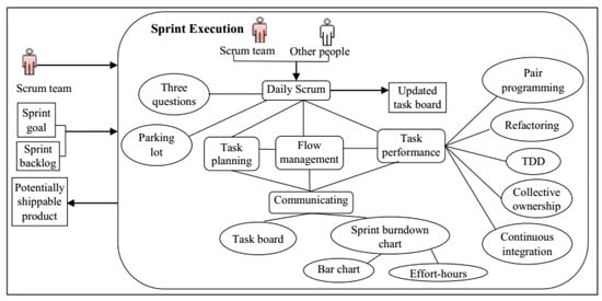
Figure 16.
Output of the tool.
In the post-questionnaire, we asked the subjects to state their opinions about the suitability of the process elements produced by the tool (Strongly agree = 5 to Not sure = 0); this section of the questionnaire was only filled out by subjects who had used Scrum in real projects (11 subjects). Details are provided in Appendix S. The average values for almost all of the process elements were greater than 4, indicating that subjects agreed with the suitability of almost all of the process elements.
4.2.3. Discussion on the Results of the Experiment
The results of this experiment indicate that subjects have perceived the proposed approach to be a useful way for defining/refining a specific process that also provides a certain level of ease of use in this regard (RQ1 and RQ2). Although we expected a certain level of time reduction in producing a specific process by using the proposed approach, the results show that there is no significant difference in the time expended on the two treatments (RQ3). This is in contradiction with the subjects’ perceived usefulness (RQ2), but the qualitative feedback provided in the open-ended questions shows that enhancing the expertise of organization people in using the tool and providing guidelines and examples on how to assign values to situational factors can reduce the time required. Comparing the results of the two treatments indicates that only 32.79% of the process elements presented as the output of the tool have been identified by the subjects in the first treatment; subjects have also generally agreed with the suitability of most of the process elements identified by the tool for the described situation. This result indicates that the output of the tool is likely to be more complete than the output of the first treatment (RQ4).
There are several threats to the validity of this experiment, including the following:
- Internal validity: There are two potential threats to the internal validity of a within-subject design. The first threat is learning effects, which we minimized by providing the subjects with the required instruments gradually and only when needed, thus leveling the learning curve; the only common instrument in the two treatments was the description of the hypothetical situation. However, as the subjects had to assign values to situational factors based on the description of the situation, they needed to carefully read each sentence of the description in the second treatment; therefore, the learning effect was minimized. Furthermore, we have intentionally designed the sequence of sessions 1 and 2 so that the tool is only used throughout the second session, thus obviating any biasing leaning effect resulting from having seen the output of the tool. The second threat is tiredness, which was handled by selecting only one activity of the Scrum framework as the object of experiment.
- Construct validity: The first threat to construct validity is misunderstanding the questions in the post-questionnaire; to deal with this, we added explanations to each measure. Furthermore, the pilot run helped ensure the completeness and understandability of the questionnaire. The second threat is that subjects might not gain sufficient understanding of the tool and the experiment’s tasks. To reduce this threat, we held a training session and sent a voice-recorded file including detailed instructions on how to execute the experiment. The within-subject design and subject limitation strategy helped reduce the effects of confounding variables [81] as the third threat to construct validity.
- Conclusion validity: One potential threat to conclusion validity is low statistical power; as we needed people with basic knowledge/experience of Scrum, we could not use a random sampling strategy to choose a large number of respondents. Another threat is the reliability of treatment implementation. We mitigated this risk by executing the whole experiment online. Furthermore, the same set of instruments was sent to all the subjects.
- External validity: The use of students as subjects of software engineering experiments is popular due to their higher availability/accessibility [82]. Although using student subjects is often seen as a potential threat to external validity, there is no general agreement that either students or professionals are generally better as subjects of experiments [82] (p. 26). Hence, we have used a combination of students and professionals in our experiment (as shown in Appendix Q); furthermore, the students who participated in the experiment had several years of experience in industrial projects. Another potential threat to external validity is having an inadequate experimental setting. To minimize this risk, we implemented the transformations in a tool that is available online; however, further experimentation is needed to generalize the findings.
4.3. Comparative Analysis
In this section, we compare our proposed approach with existing SPrLE approaches based on the support that they provide for feasibility analysis, enhancement of the core process, management of configuration complexity, and post-derivation enhancement; these are the four activities that we had identified as areas requiring improvement in existing model-driven SPrLE approaches (as explained in Section 2). Table 7 shows the results of evaluating our approach and existing model-driven SPrLE approaches based on their support for these four activities. It should be mentioned that tool-focused approaches [27,30,32] and approaches for proposing general SPrLs for specific domains [33,34] have been excluded from this comparison, as they cannot be considered as specialized engineering approaches for constructing bespoke SPrLs.

Table 7.
Results of evaluating SPrLE approaches based on their support for the four SPrLE activities.
Results of the comparison are explained below:
- Feasibility analysis in our approach is conducted in the analysis subphase of DE. No other approach provides mechanisms for this purpose.
- Enhancing the core process is performed in our approach via defining a metaprocess by applying the top-down approach, and then merging it with the initial core process. In [21,22,23], the top-down approach is used for creating the SPrL; however, the processes used in the organization are not analyzed to create the core process, whereas these processes may include specific process elements for specific situations that are not identified by the top-down approach. Therefore, the combination of bottom-up and top-down approaches has never been used before, and is a contribution of our proposed SPrLE approach.
- Managing configuration complexity is performed in our approach in two ways: automatic variability resolution and support for multistage configuration through multilevel resolution of variabilities. In [10,12,21,22,23,25,26,28,31], configuration complexity is managed by providing automation in resolving the variabilities. Multistage configuration of variabilities is implicitly supported in [21,22,23], but not in [10,12,25,26,28,31]; therefore, we have assigned the value “Partial-support” to [10,12,25,26,28,31] for managing configuration complexity. In [21], resolution of the variabilities defined in the SPrL results in creating a specific SPrL for the target organization; the target organization should then resolve the remaining variabilities to create the specific processes. In [22,23], variants of the reference model are created at different abstraction levels: company-specific level, unit-specific level, and project-specific level. There are two specific differences between the multi-stage configuration proposed in our approach with the one used in [21,22,23]: 1) We do not limit the number of levels through which the variabilities are resolved; organizations can define the levels based on their needs and by using the framework proposed (Figure 7); and 2) We exactly specify which variation points are resolved at which levels. This level of detail is not provided in [21,22,23]; however, as these studies have paid adequate attention to this aspect of complexity management, we have assigned the value “Full-support” to them for managing configuration complexity
- Post-derivation enhancement is performed in our approach in the implementation subphase of AE by analyzing the process instantiated from the SPrL to identify delta requirements; PIMB is then used to address those requirements. No other approach provides mechanisms for this purpose.
5. Discussion on the Benefits and Limitations of the Proposed Approach
The proposed approach provides concrete benefits. Automatic execution of transformations has many advantages: building a process is done in a systematic manner, since the transformations are uniformly executed based on the values of context attributes; furthermore, the time required for building a specific process is shorter than before, so any change in the context model, values of context attributes, and transformation rules can be propagated to process models faster and easier. Gradual resolution of variabilities through modeling levels has many benefits too, including enhancing the maintainability, complexity management, and reusability of models. Our approach also covers post-derivation activities: after a specific process is built, it is analyzed to identify the organizational-needs/project-characteristics that have not been satisfied; in case such shortcomings are found, the PIMB is used for identifying suitable process elements for resolving them. Using PIMB and enriching it over time with best practices can help enhance the maturity of processes; it can also help share process knowledge across the organization.
However, evaluation results indicate that there are specific limitations in using the approach, including the following:
- (1)
- Although providing tool support for representing variabilities and executing transformations has its own benefits, user-friendliness is an important feature that should be considered when implementing a tool; this requirement has not been adequately satisfied by our proposed tool. This may jeopardize the adoption of the approach by organizations.
- (2)
- Although automatic execution of transformations can facilitate change propagation, it is imperative that specific mechanisms be provided for preserving traceability between the SPrL and the processes already instantiated from it. Our approach lacks such mechanisms, to the detriment of the evolvability of the SPrL.
- (3)
- Another challenge is assigning specific values to situational factors during AE. Our approach fails to provide guidelines on how to assign these values based on the structure of the organization/teams and the type of the project at hand.
6. Conclusions and Future Work
Our proposed SPrLE approach is executed in two phases: Domain Engineering (DE), and Application Engineering (AE). During the DE phase, a context model is created along with a core process. During the AE phase, specific processes are built for the organization by resolving the variabilities of the core process. The MDD approach is explicitly used in this phase: transformations are automatically executed, gradually generating the model of the target process as it passes through the modeling levels; these transformations are based on the core process and the context model. Evaluation and comparative analysis have shown that the proposed approach is applicable to real situations, is useful and easy to use, and is superior to existing SPrLE approaches as to the support that it provides for the four SPrLE activities that have been found to be deficient in existing approaches. The proposed approach can be used by process engineers to create an SPrL and by project managers to build a bespoke process. It helps process engineers to examine the suitability of the SPrL approach for an organization and to then create the core process by following a multi-step bottom-up approach. If the organization’s processes are based on Scrum, the process engineer can use our proposed metaprocess [56] to improve the initial core process; in such cases, the transformations implemented in the tool can be reused. However, if the processes are not based on Scrum, the process engineer should create a metaprocess by identifying the variabilities in a well-known framework. The multi-level modeling provided in our approach can be used to manage the inherent complexity involved in variability resolution.
Although the resolution of variabilities in the proposed approach is performed automatically, the next step for facilitating the adoption of SPrLs in organizations is providing a high level of user friendliness in the user interface of the tool used for executing the transformations. This research can be furthered in several other directions as well, such as extending PIMB with additional practices, empirically evaluating the metamodel proposed for modeling SPrLs, conducting more case studies to evaluate the approach’s practicality in different contexts, providing mechanisms to define traceability relationships between the core process and instantiated processes to facilitate change propagation and identification of situations for evolving the constructed SPrL, and providing organizations with guidelines on how to assign values to context attributes based on different organizational/team structures and project categories.
Author Contributions
Conceptualization, H.A. and R.R.; methodology, H.A. and R.R.; software, H.A.; validation, H.A. and R.R.; formal analysis, H.A.; investigation, H.A.; resources, R.R.; data curation, H.A.; writing—original draft preparation, H.A.; writing—review and editing, R.R.; visualization, H.A.; supervision, R.R.; project administration, R.R. All authors have read and agreed to the published version of the manuscript.
Funding
This research received no external funding.
Institutional Review Board Statement
Not applicable.
Informed Consent Statement
Not applicable.
Data Availability Statement
The data supporting the reported results has been uploaded to Mendeley Data and can be found at: https://data.mendeley.com/datasets/r62gjghx52/1 (accessed on 22 November 2022). This link has also been added to the list of references (Reference 64) and has been referred to in the manuscript where necessary.
Conflicts of Interest
The authors declare no conflict of interest.
Appendix A
To clarify the application of requirements for feasibility analysis purposes, consider an organization in which the importance level of requirements has already been specified by conducting one or more case studies, shown in the second column of Table A1. Furthermore, suppose that the threshold value has been set to 10. The evaluation of requirements in the organization is shown in the third column of Table A1. Each cell of the second column should be multiplied by the corresponding cell in the third column; summing up the results shows the satisfaction level of requirements in the organization, shown in the fourth column of Table A1. Since the total score (13) is greater than the threshold value (10), the organization is a suitable candidate for creating the SPrL.

Table A1.
An example of application of requirements for deciding about creating the process line.
Table A1.
An example of application of requirements for deciding about creating the process line.
| Requirement | Level of Importance (0–10) | Satisfaction by Organization (Yes = 1, No = 0) | Score |
|---|---|---|---|
| Significantly different criticality levels in different products | 3 | 1 | 3 |
| Projects of significantly different sizes/durations undertaken | 5 | 1 | 5 |
| Resource constraints | 1 | 0 | 0 |
| Specific level of similarity as to the structure of methodologies | 2 | 1 | 2 |
| Similarity in type of methodologies | 3 | 1 | 3 |
| Sum = 13 | |||
Appendix B
Figure A1 shows an example of modeling context attributes in Medini QVT; instances of the classes defined in the metamodel have been highlighted in this figure.
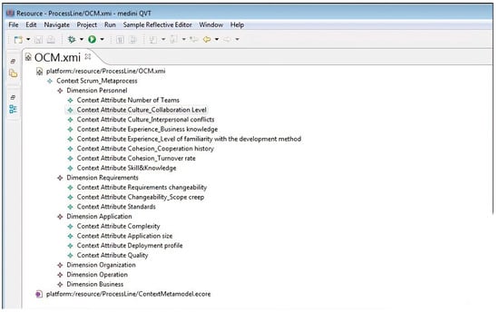
Figure A1.
An instance of the context metamodel implemented in the Medini-QVT tool.
Appendix C
Figure A2 shows an example of the variability modeling performed in the tool. Variabilities have been signified by the keyword “Variation Point”.
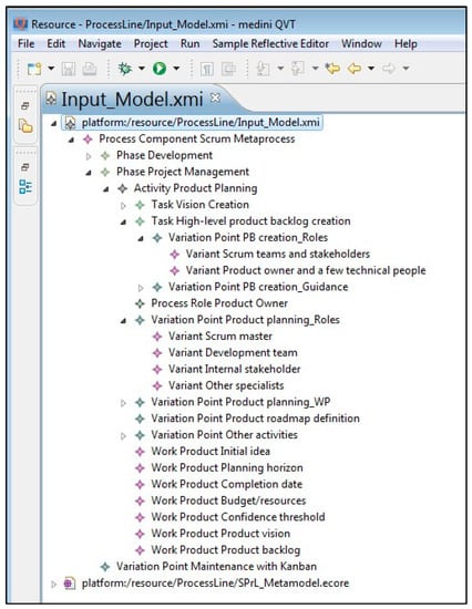
Figure A2.
Variabilities modeled via the Medini-QVT tool (signified by the keyword “Variation Point”).
Appendix D
Figure A3 shows an example of the variabilities identified in this metaprocess. The metaprocess has been implemented in the tool; however, Figure A3 shows a manually-produced graphical view of it. To clarify the variabilities identified in the “Grooming the product backlog” activity, consider the “Prioritizing PBIs” task. Prioritizing backlog items can be performed based on four guidances: cost, value, knowledge, and risk. If “Value” is selected, there are two ways for prioritizing PBIs based on “Value”: Kano analysis and Relative weighting; one of these guidances should be selected, since these variants are connected to a variation point with the Alternative-XOR relationship.
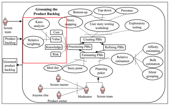
Figure A3.
Variabilities identified in “Grooming the product backlog”.
Appendix E
The process elements defined in PIMB are shown in Table A2. For each process element (practice), the situation in which the process element can be used has also been identified. The sign ‘*’ in the table means that the value assigned to the factor has no effect on resolving the variation point.

Table A2.
Process elements defined in PIMB.
Table A2.
Process elements defined in PIMB.
| Practice | Situation |
|---|---|
| Post-mortem session | Personnel cohesion = (*, High) OR Application connectivity = High |
| Feasibility study | Degree of risk = High OR Application complexity = High OR Personnel experience = (Inexperienced, *) |
| Prototyping | Personnel experience = (Inexperienced, *) OR Requirements standards = Inadequate OR Application complexity = High OR Degree of risk = High OR End-user experience = Inadequate |
| Facilitated workshops | (Number of teams = High OR External dependencies = High) AND Organization facilities = Adequate |
| Coding standards | Number of teams = High OR Personnel cohesion = (*, High) OR Application connectivity = High OR Application reuse = High OR Application quality = High |
| Simple design | Personnel skill and knowledge = Inadequate OR Application reuse = High OR Application quality = High |
Exploring the method base is automatically performed by executing transformations. Input models to transformations are the method base and the context model. An excerpt of the PIMB defined in the tool is shown in Figure A4.
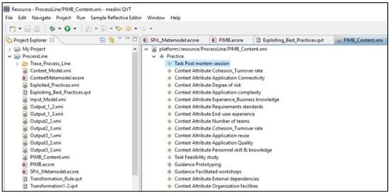
Figure A4.
Excerpt of PIMB defined in the tool.
Appendix F
Table A3 shows an excerpt of the transformation implemented for resolving the “Pair programming” variability in the Scrum metaprocess; pair programming is an optional guidance and should be added to the target process by considering the values of context attributes. In Table A3, Part 1 checks if specific context attributes have been assigned specific values. The process element related to the “pair programming” guidance is specified in Part 2. In Part 3, the guidance is added to the process element. Parts 1 and 2 constitute the ‘before’ state of the transformation, whereas Part 3 denotes the ‘after’ state.

Table A3.
An excerpt of the transformation implemented for resolving “Pair programming”.
Table A3.
An excerpt of the transformation implemented for resolving “Pair programming”.
| QVT Definition | Top Relation Rule9 |
|---|---|
| Part 1 | checkonly domain left1 L1: Context_Metamodel::Context{ Contains = D1: Context_Metamodel::Dimension { Name = ‘Application’, Contains = C1: Context_Metamodel::ContextAttribute { Name = ‘Quality’, Value = ‘High’}}}; |
| Part 2 | checkonly domain left2 L2: SPrL_Metamodel::Task{ Name = ‘Task performance’}; |
| Part 3 | enforce domain right R1: SPrL_Metamodel::Guidance{ Name = ‘Pair programming’, Is_Contained_by_Task = L2};} |
Appendix G
To provide an overall overview, examples of the work products of DE subphases are shown in Figure A5. As shown in this figure, two different instances of Scrum have been fed to the analysis subphase (X and Y); we have just shown an excerpt of “Grooming product backlog” activity in this example. Organizational goals are used to help identify the context attributes that are important to the organization. Models of the two processes and a set of context attributes are the outputs of the analysis subphase. During design, context attributes are modeled by instantiating the context metamodel. As shown in Figure A5, one variability has been identified between the two processes. Different criteria are used for prioritizing PBIs: “Value” in X, and “Value” and “Knowledge” in Y; hence, “Value” is added as mandatory, whereas “Knowledge” is specified as optional. During implementation, the core process is completed by combining the initial core process with the Scrum metaprocess. The details and variabilities of the “Grooming product backlog” activity of the metaprocess are more comprehensive than the same activity in the initial core process. Therefore, the result of combination will be the same as the activity defined in the metaprocess, as shown in Figure A3. However, if the initial core process had included process elements other than the ones in the metaprocess, they would have shown up in the combined process. Transformations are also produced in this subphase. PIMB is the other output produced.
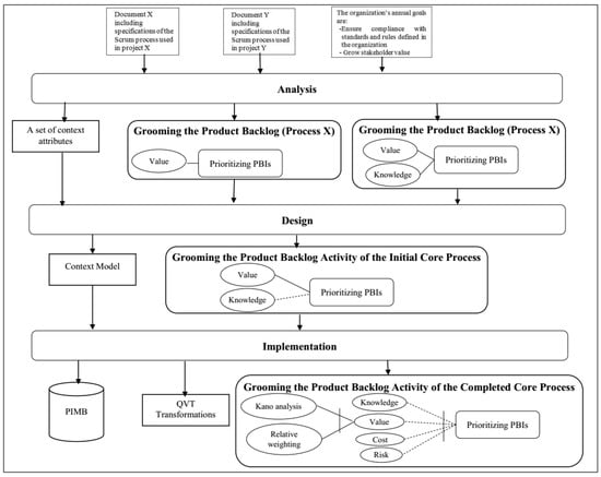
Figure A5.
Examples of work products of DE subphases.
Appendix H
Figure A6 shows an example of an OCM implemented in the tool. As shown in Figure A6, the value of “Culture Collaboration Level” has been set to “Collaborative”.
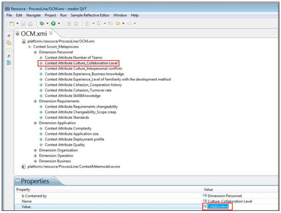
Figure A6.
The Organizational Context Model (OCM) implemented in the tool.
Appendix I
Figure A7 shows an example of the resolution of the variabilities related to the “Sprint Execution” activity, which only includes role, task, and guidance variabilities, the resolution of which depends on environmental and project factors; therefore, there is no resolvable variation point at levels 1.1 to 2.1, and 3.1. Resolution is performed as follows:
- Transformation 2.2: Sprint Execution and the OCM are fed to this transformation. For sake of brevity, only the relevant parts of the activity are shown in Figure A7. Variation points that are dependent to environmental factors (Tasks, Work Products, and Roles) are resolved at this level; therefore, “Daily Scrum”, which is designated as an optional task in the input model, is resolved by executing the transformation. Based on the values assigned to the situational factors, this task is added to the target process.
- Transformation 2.3: The Sprint Execution produced at level 2.2 and the OCM are fed to this level as input models. Variation points that are dependent to project factors are resolved at this level (Guidance); therefore, “Three questions”, designated as an optional guidance, is resolved by executing the transformation. Based on the values assigned to situational factors, this guidance is added to the target process.
- Transformation 3.2: The Sprint Execution produced at level 2.3 and the OCM are fed to this transformation as input models. Roles that are dependent to project factors are resolved at this level; therefore, “Other people”, designated as an optional role, is targeted by the transformation. Based on the values assigned to situational factors, “other people” is added to the target process as a role involved in the Daily Scrum.
- Transformation 3.3: All the remaining variabilities are resolved at this level. Based on the values assigned to situational factors, “Pair programming”, “Refactoring”, “TDD”, “Collective ownership”, “Continuous integration”, “Parking lot chart”, “Task board”, “Sprint burndown line chart”, and “Effort-hours” are added to the target process. By adding the “Sprint burndown chart” to the target process, the “Sprint burnup chart”, and the guidances associated with “Sprint burnup chart” (“Story point” and “Effort-hours”) are removed from the core process since there is an exclusion relationship between “Sprint burndown chart” and “Sprint burnup chart”. “CFD” is also removed based on the values of situational factors. The resulting “Sprint Execution” activity is the output of level 3.3.
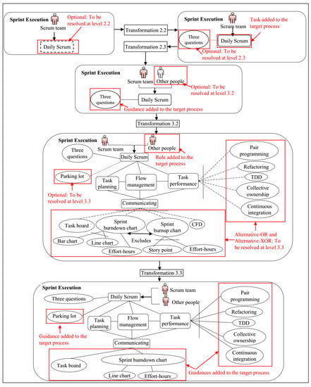
Figure A7.
Resolution of “Sprint Execution” variabilities for a specific situation.
Appendix J
Examples of AE work products are shown in Figure A8. In the analysis subphase, context attributes are given specific values and the organizational context model is produced. During design, the variabilities defined in the “Grooming product backlog” activity are resolved by executing the pre-defined transformations (based on the values of context attributes); we have shown just an excerpt of the activity due to space limitations. Variabilities are resolved gradually by traversing the modeling levels and executing the relevant transformations; due to space limitations, only the output of level 3.3 is shown herein as the output of the design subphase (Figure A8). During implementation, the “Facilitated workshops” guidance is extracted from PIMB and added to the “Prioritizing PBIs” task.
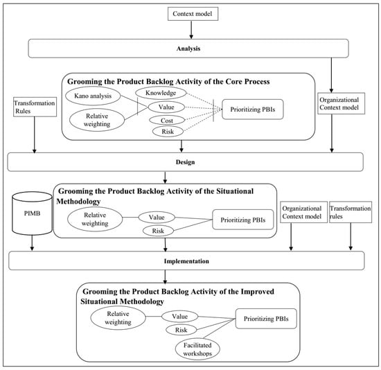
Figure A8.
Examples of work products of AE subphases.
Appendix K
The questionnaire designed for feasibility analysis is shown in Table A4. It was filled out by three of the four candidate companies. One of the companies stated that only one category of products was developed by this company and they used only one version of Scrum; therefore, the questionnaire was not filled out by this company. We used a weighting approach to examine the candidate companies, in which a Yes/No answer was given to each question, scored as: “Yes/Y” = 1, and “No/N” = 0. As the requirements in the organization category are meaningful for only those organizations that have headquarters in different locations, such as multi-national or international companies [13], the questions included in this category have been answered by only one of the companies.

Table A4.
Feasibility analysis questionnaire filled out by three companies.
Table A4.
Feasibility analysis questionnaire filled out by three companies.
| Category | Requirement for Adopting SPrL | Candidate Companies | ||
|---|---|---|---|---|
| A | B | C | ||
| Product | Significantly different criticality levels in different products | Y | Y | Y |
| Significantly different product types produced | N | Y | Y | |
| Significantly different product sizes produced | Y | Y | Y | |
| Significantly different security levels in different products | N | N | N | |
| Significantly different complexity levels in different products | Y | Y | N | |
| Significantly different maintainability needs in different products | Y | N | Y | |
| Significantly different usability needs in different products | N | N | N | |
| Significantly different performance efficiency levels in different products | N | Y | N | |
| Significant difference in the level of compatibility with organization laws/standards, or with existing systems, in different products | Y | N | N | |
| Significantly different reliability needs in different products | N | N | N | |
| Significantly different complexity levels in predicting the requirements/project schedule/project cost in different products | Y | N | Y | |
| Significantly different levels of rigidity in meeting stated and implied needs of products | Y | N | N | |
| Project | Significantly different levels of resource constraints in different projects | Y | N | N |
| Significant difference in the level of team members’ skill/knowledge in different projects | Y | Y | N | |
| Projects of significantly different sizes/durations undertaken | Y | Y | Y | |
| Significantly different risk/complexity levels in different projects | Y | Y | Y | |
| Significant difference in the number or size of teams in different projects | Y | Y | N | |
| Significant difference in changeability, understandability, or feasibility of user/system requirements in different projects | N | N | N | |
| Significant difference in the level of stakeholder involvement, number of stakeholders involved, and/or background/knowledge level of stakeholders in different projects | Y | N | N | |
| Significant difference in team cohesion (Distributed/Collocated) in different projects | N | N | N | |
| Significantly different project types undertaken (i.e., outsourced and insourced) | N | Y | N | |
| Significant difference in technological environments (tool infrastructures, test environments, COTS products) and/or architectural decisions in different projects | N | N | N | |
| Significant difference in the level of cooperation, cooperation history, and/or disharmony among team members, in different projects | N | Y | N | |
| Variable types of development (developing new systems/modification of existing systems) undertaken in different projects | N | Y | N | |
| Significant difference in contract types (fixed date/fixed price) and/or the level of interaction between contractor and developers in different projects | N | N | N | |
| Significant difference in customer cohesion and/or customer variety in different projects | N | N | Y | |
| Significant difference in the degree of novelty and/or the level of technology emerging in different projects | N | N | Y | |
| Significantly different productivity levels in the teams involved in different projects | Y | N | N | |
| Significant difference in the availability of legacy system information in different projects | Y | N | N | |
| Significant difference in the level of end-user variety, their availability, and/or their experience with the system in different projects | N | N | N | |
| Significant difference in the number of deployed versions of applications, or the number of deployed applications in different projects | Y | Y | N | |
| Significant difference in importance of user interface in different projects | Y | N | N | |
| Significant difference in the rate at which emergent opportunities occur in different projects | Y | Y | Y | |
| Significant difference in the importance of status information for the top management in different projects | Y | N | N | |
| Significant difference in the level of team members´ skill/knowledge in different projects | Y | N | N | |
| Organization | Significant difference in sizes of distributed organizations | N | -- | -- |
| Significant difference in structure/culture of distributed organizations | Y | -- | -- | |
| Significant difference in maturity levels of distributed organizations | N | -- | -- | |
| Significantly different levels of resource constraints in different organizations | N | -- | -- | |
| Significant difference in the level of commitment, support, expertise, availability, accomplishment, and/or continuity among the managers | N | -- | -- | |
| Significantly different crucial forces behind the successful development of a project in different organizations | Y | -- | -- | |
| Significantly different product types in different organizations | Y | -- | -- | |
| Significant difference in standards or legal aspects | N | -- | -- | |
| Significantly different stability levels in different organizations | N | -- | -- | |
| Significantly different innovation levels in different organizations | N | -- | -- | |
Appendix L
Semi-structured interviews were the main source of information in the case study. Interview instruments were constructed to focus on the areas to discuss. The instruments were adapted as the interviews progressed to gain further information about the process used in the organization and its problems. The interview instruments used are as follows:
Appendix L.1. Session 1
- General (~15 min): Focusing on subjects’ personal history and details of the projects performed in the specific unit;
- Explaining the study (~30 min): Focusing on the goals of the study, the proposed approach for creating the process line, how the subjects will benefit from the results, and guaranteeing the confidentiality and anonymity of the gathered data;
- Problems and challenges (~15 min): Focusing on the main problems and challenges that subjects face in projects.
Appendix L.2. Session 2
- Scrum process (~60 min): Focusing on how the subjects perform Scrum activities (including Portfolio Planning, Product Planning, Release Planning, Sprint Planning, Sprint Execution, Grooming, Sprint Review, and Sprint Retrospective), what roles are involved in each activity, what products are produced or received in each activity, the other activities performed, guidance/techniques used in each activity, and the problems faced when performing each activity.
Appendix L.3. Session 3
- Process line created (~25 min): Focusing on explaining the existing process line along with the process line proposed for the organization;
- Target process created for the specific project (~25 min): Focusing on explaining the specific process instantiated from the process line, and the mapping relationships between the problems of the unit and the practices defined in the proposed process;
- Subjects’ feedback on the proposed approach (~10 min);
- Ending (~5 min): Focusing on finishing with a brief summary, thanking the subject, and scheduling a feedback after applying some of the proposed practices.
Appendix M
The values of context attributes in project A.2 are shown in Table A5.

Table A5.
Values of context attributes in project A.2.
Table A5.
Values of context attributes in project A.2.
| Factor Class | Situational Factors | Value Assigned |
|---|---|---|
| Personnel | Number of Teams | Normal |
| Culture | (Collaborative, Harmonious) | |
| Experience | (Experienced, Unfamiliar) | |
| Cohesion | (Normal, Normal) | |
| Skill and Knowledge | Adequate | |
| Commitment | Adequate | |
| Requirements | Changeability | (High, Normal) |
| Standards | Adequate | |
| Application | Degree of Risk | High |
| Complexity | Normal | |
| Size | Normal | |
| Connectivity | High | |
| Reuse | High | |
| Deployment Profile | High | |
| Quality | High | |
| Organization | Maturity | Adequate |
| Management Commitment and Expertise | (Adequate, Adequate) | |
| Facilities | Adequate | |
| Operation | End-User Experience | Adequate |
| Business | Time to Market | Normal |
| External Dependencies | Normal | |
| Opportunities | Normal | |
| Business Drivers | Financial considerations and Maximizing customer satisfaction | |
| Magnitude of Potential Loss | Normal |
Appendix N
Figure A9 shows the transformation implemented for resolving the variability related to “Maintenance with Kanban”.
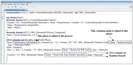
Figure A9.
Transformation implemented for resolving the variability related to “Maintenance with Kanban”.
Appendix O
For obtaining feedback on the impact of the process elements applied in project A.2, we designed a questionnaire through which participants were asked to state their opinion on whether each of the practices listed in Figure A10 would result in improving the process being used in their project.

Figure A10.
Questionnaire designed for obtaining feedback about the practices applied.
Appendix P
Examples of problems in existing processes and the solutions proposed based on the produced processes are presented in Table A6.

Table A6.
Problems identified through interview sessions and the solutions proposed for each.
Table A6.
Problems identified through interview sessions and the solutions proposed for each.
| Project | Problems and Solutions |
|---|---|
| A.1 | Problem: The capacity of team to complete work and then forecasting PBIs deliverable in the upcoming sprint is determined by an experienced person who has enough knowledge about capabilities of team members. Any change in the structure of the team can threat estimations performed. Solution: Specific guidances, including Velocity, Planning poker, and Story point are proposed. |
| Problem: User stories defined in the product backlog are not split into tasks. Solution: It is proposed that Sprint goal be defined for each sprint. Furthermore, specific process elements, including Sprint backlog, and Task board are proposed. | |
| Problem: Due to time constraints, unit testing is not performed; only black-box testing is automatically performed for validating PBIs implemented through the current sprint. Solution: Specific guidances, including Definition of ready and Definition of Done are proposed. | |
| Problem: The size of PBIs is not properly estimated. Solution: Planning poker is proposed. | |
| A.2 | Problem: Some of the top-most PBIs are not groomed into a ready state. Solution: The guidance “Definition of ready criteria” is proposed. |
| Problem: The capacity of team to complete work and then forecasting PBIs deliverable in the upcoming sprint is determined by an experienced person who has enough knowledge about capabilities of team members. Any change in the structure of the team can threat estimations performed. Solution: Specific guidances, including Velocity, Planning poker, and Story point are proposed. | |
| Problem: The size of PBIs is not properly estimated. Solution: Specific guidances, including Planning poker and Story point are proposed. | |
| Problem: PBIs implemented in the current sprint are not properly presented to the product owner in sprint reviews. Solution: Definition of Done is proposed. Furthermore, defining the “How to Demo” template for specifying contents that should be presented throughout sprint review meetings can help solve the problem. | |
| A.3 | Problem: Prioritizing PBIs are not performed properly. Solution: Considering Cost, Value, Knowledge, and Risk factors for prioritizing PBIs is proposed. |
| Problem: The product backlog is not groomed in just-enough and just-in-time manner. Solution: Specific process elements, including Definition of ready, Planning Poker, and Task board are proposed. | |
| A.4 | Problem: The size of PBIs is not properly estimated. Solution: Specific guidances, including Planning poker and Story point are proposed. |
| Problem: There are problems with intra-team knowledge sharing. Solution: Guidances such as “Moving people around” and “Preparing documents of project status” are proposed. | |
| Problem: The capabilities of team members in writing high-quality code are significantly different from each other. Solution: “Training team members on code quality by a coach” guidance is proposed. |
Appendix Q
The demographic data of the subjects is shown in Table A7.

Table A7.
Demographic data of the subjects.
Table A7.
Demographic data of the subjects.
| No. | Current Work Status | Highest Academic Degree | Number of Projects Participated in | Experience in Using Scrum | Passed University Courses Related to Process Engineering Including Scrum |
|---|---|---|---|---|---|
| 1 | Professional | MSc | 10+ | Yes | Yes |
| 2 | Professional | MSc | 1–2 | Yes | Yes |
| 3 | Academic | MSc | 8–10 | Yes | Yes |
| 4 | Academic | MSc | 3–4 | No | Yes |
| 5 | Professional | MSc | 5–7 | Yes | Yes |
| 6 | Academic | MSc | 1–2 | No | Yes |
| 7 | Professional | MSc | 10+ | Yes | Yes |
| 8 | Professional | MSc | 3–4 | No | Yes |
| 9 | Academic | MSc | 8–10 | Yes | Yes |
| 10 | Professional | MSc | 8–10 | Yes | Yes |
| 11 | Professional | MSc | 10+ | Yes | Yes |
| 12 | Academic | PhD | 8–10 | Yes | Yes |
| 13 | Academic | MSc | 10+ | Yes | Yes |
| 14 | Professional | MSc | 5–7 | Yes | Yes |
Appendix R
A hypothetical project situation was considered as the experiment object. Subjects defined Sprint execution suitable for this situation throughout two treatments. The description of this situation is as follows:
“We consider a hypothetical software development project in a small-sized software company as an example project situation. The company is CMMI level-2 certified, and its organizational software process is based on Scrum. The application to be built is a medium-sized, web-based application with high complexity. End-users have already used applications similar to the new one, and there are representatives of the end-user community that are capable of specifying the user requirements with high quality; however, these requirements can be changed easily over time in response to market needs. There is considerable time pressure to release the first version of the application by implementing a portion of the requirements that significantly increases customer satisfaction. The quality of the application is vital for the customer organization, and the competitive edge of the organization can be seriously affected if quality standards are not observed. One Scrum team, consisting of one Scrum master, one product owner and a development team of five, is responsible for building the application. Development team members are technical people who have worked together for two years, but they are unfamiliar with the application to be built. The development team is collocated in a collaborative workspace. The company and its managers provide adequate support to the Scrum team; e.g., by providing the facilities required for implementing agile practices.”
Appendix S
To gather subjective data, we designed a two-part questionnaire. The first part was designed to evaluate the users’ perceived usefulness and ease of use. The second part was designed to measure the completeness of the process produced (as a measure of its effectiveness). Contents of each part are as follows:
Part 1: Subjects were asked to state their opinion on whether each of the characteristics shown in Figure A11 is improved by using the proposed approach rather than using the ad hoc approach for defining an instance of Scrum.
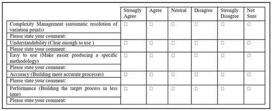
Figure A11.
Questionnaire designed for measuring perceived usefulness and ease of use.
Part 2: In this part, subjects were asked to state their opinion about the suitability of the process elements identified by the tool for the described situation. The responses given by the subjects are shown in Table A8.

Table A8.
Responses given to the suitability of the process elements identified by the tool.
Table A8.
Responses given to the suitability of the process elements identified by the tool.
| Strongly Agree | Agree | Neutral | Strongly Disagree | Disagree | Not Sure | Min | Max | Avg. | ||
|---|---|---|---|---|---|---|---|---|---|---|
| Sprint Execution | Scrum Team | 9 | 2 | 0 | 0 | 0 | 0 | 4 | 5 | 4.82 |
| Sprint Goal | 9 | 1 | 0 | 0 | 0 | 1 | 0 | 5 | 4.45 | |
| Sprint Backlog | 9 | 1 | 0 | 0 | 0 | 1 | 0 | 5 | 4.45 | |
| Potentially Shippable Product | 7 | 2 | 1 | 0 | 0 | 1 | 0 | 5 | 4.18 | |
| Daily Scrum | 8 | 3 | 0 | 0 | 0 | 0 | 4 | 5 | 4.73 | |
| Task Performance | 6 | 3 | 1 | 0 | 0 | 1 | 0 | 5 | 4.09 | |
| Flow Management | 4 | 2 | 1 | 0 | 0 | 4 | 0 | 5 | 2.82 | |
| Task Planning | 6 | 4 | 1 | 0 | 0 | 0 | 3 | 5 | 4.45 | |
| Communicating | 8 | 0 | 2 | 0 | 0 | 1 | 0 | 5 | 4.18 | |
| Daily Scrum | Scrum Team | 8 | 3 | 0 | 0 | 0 | 0 | 4 | 5 | 4.73 |
| Other People | 2 | 3 | 4 | 1 | 0 | 1 | 0 | 5 | 3.27 | |
| Parking Lot | 1 | 4 | 6 | 0 | 0 | 0 | 3 | 5 | 3.54 | |
| Three Questions | 5 | 3 | 3 | 0 | 0 | 0 | 3 | 5 | 4.18 | |
| Task Performance | Pair Programming | 2 | 4 | 3 | 0 | 2 | 0 | 1 | 5 | 3.36 |
| TDD | 8 | 1 | 2 | 0 | 0 | 0 | 3 | 5 | 4.54 | |
| Refactoring | 8 | 3 | 0 | 0 | 0 | 0 | 4 | 5 | 4.73 | |
| Collective Ownership | 6 | 3 | 2 | 0 | 0 | 0 | 3 | 5 | 4.36 | |
| Continuous Integration | 10 | 1 | 0 | 0 | 0 | 0 | 4 | 5 | 4.91 | |
| Communicating | Sprint Burndown Chart | 3 | 5 | 2 | 0 | 0 | 1 | 0 | 5 | 3.73 |
| Task Board | 9 | 2 | 0 | 0 | 0 | 0 | 4 | 5 | 4.82 | |
| Burndown Chart | Bar Chart | 2 | 2 | 5 | 0 | 0 | 2 | 0 | 5 | 3 |
| Effort-hours | 2 | 1 | 5 | 1 | 1 | 1 | 0 | 5 | 2.91 | |
| Total Average = 4.1 | ||||||||||
Legend: 5. Strongly agree/4. Agree/3. Neutral/2. Disagree/1. Strongly disagree.
Appendix T
Since the subjects were geographically distributed, the experiment was executed in an online manner. Therefore, the following set of instruments was sent to the subjects:
- Introductory document: The experiment goal and the tasks of the study were explained through this document.
- Description of hypothetical situation
- List of situational factors along with range of values
- Transformations package: Transformations implemented for resolving the variabilities of Sprint Execution were sent to the subjects via this package.
- Voice-recorded power point presentation: A voice-recorded presentation was sent to the subjects before the experiment execution. Through this file, we explained the subjects how to install and configure the tool. We also provide subjects with an example of assigning values to situational factors and executing transformations for resolving the variabilities of Release Planning.
- Pre-questionnaire: The demographic data were gathered through this questionnaire.
- Post-questionnaire: The perceived usefulness and ease of use were quantified through this questionnaire. Furthermore, the suitability of the process elements identified by the tool was measured via this questionnaire.
Appendix U
To measure the effectiveness of the proposed approach, we compared the instances of “Sprint Execution” produced in the two treatments. The results of this comparison are shown in Table A9. As shown in this table, only 32.79% of the process elements specified by the tool (through our proposed approach) were identified by the subjects in the ad hoc treatment. The fourth column of Table A9 shows the different words used by the subjects for naming the process elements of Sprint Execution.

Table A9.
Comparison of the process elements identified in the two treatments.
Table A9.
Comparison of the process elements identified in the two treatments.
| Number of Subjects Identifying the Process Element | Different Words Used | ||
|---|---|---|---|
| Sprint Execution | Scrum Team | 14 | ----- |
| Sprint Goal | 4 | ----- | |
| Sprint Backlog | 8 | ----- | |
| Potentially Shippable Product | 9 | Potentially shippable increment, Deployable product, Increment, Potential product, Working application | |
| Daily Scrum | 10 | Daily meeting, face to face conversations | |
| Task Performance | 14 | Develop task, Development | |
| Flow Management | 4 | Review and Revise | |
| Task Planning | 5 | ----- | |
| Communicating | 3 | ----- | |
| Daily Scrum | Scrum Team | 10 | ----- |
| Other People | 1 | ----- | |
| Parking Lot | 1 | ----- | |
| Three Questions | 0 | ----- | |
| Task Performance | Pair Programming | 3 | ----- |
| TDD | 2 | ----- | |
| Refactoring | 4 | ----- | |
| Collective Ownership | 3 | ----- | |
| Continuous Integration | 4 | ----- | |
| Communicating | Sprint Burndown Chart | 0 | ----- |
| Task Board | 2 | ----- | |
| Burndown Chart | Bar Chart | 0 | ----- |
| Effort-hours | 0 | ----- | |
| Average = 32.79% | |||
References
- Acuna, S.T.; Antonio, A.D.; Ferre, X.; Lopez, M.; Mate, L. The Software Process: Modelling, Evaluation and Improvement. In Handbook of Software Engineering and Knowledge Engineering; Chang, S.K., Ed.; World Scientific: Singapore, 2000; pp. 193–238. [Google Scholar] [CrossRef]
- Pedreira, O.; Piattini, M.; Luaces, M.R.; Brisaboa, N.R. A systematic review of software process tailoring. ACM SIGSOFT Softw. Eng. Notes 2007, 32, 1–6. [Google Scholar] [CrossRef]
- Mirbel, I.; Ralyté, J. Situational method engineering: Combining assembly-based and roadmap-driven approaches. Requir. Eng. 2006, 11, 58–78. [Google Scholar] [CrossRef]
- Agh, H.; Ramsin, R. A pattern-based model-driven approach for situational method engineering. Inf. Softw. Technol. 2016, 78, 95–120. [Google Scholar] [CrossRef]
- Ocampo, A.; Bella, F.; Münch, J. Software process commonality analysis. Softw. Proc. Improv. Pract. 2005, 10, 273–285. [Google Scholar] [CrossRef][Green Version]
- Washizaki, H. Building Software Process Line Architectures from Bottom Up. In Proceedings of the 7th International Conference on Product-Focused Software Process Improvement (PROFES), Amsterdam, The Netherlands, 12–14 June 2006; pp. 415–421. [Google Scholar] [CrossRef]
- Jaufman, O.; Münch, J. Acquisition of a project-specific process. In Proceedings of the 6th International Conference on Product-Focused Software Process Improvement (PROFES), Oulu, Finland, 13–18 June 2005; pp. 328–342. [Google Scholar] [CrossRef]
- Pohl, K.; Böckle, G.; van der Linden, F. Software Product Line Engineering: Foundations, Principles and Techniques; Springer: Berlin/Heidelberg, Germany, 2005. [Google Scholar]
- Northrop, L.M. SEI’s Software Product Line Tenets. IEEE Softw. 2002, 19, 32–40. [Google Scholar] [CrossRef]
- Hurtado Alegría, J.A.; Bastarrica, M.C. Building Software Process Lines with CASPER. In Proceedings of the International Conference on Software and Systems Process (ICSSP), Zurich, Switzerland, 2–3 June 2012; pp. 170–179. [Google Scholar] [CrossRef]
- Armbrust, O.; Katahira, M.; Miyamoto, Y.; Münch, J.; Nakao, H.; Ocampo, A. Scoping Software Process Lines. Softw. Proc. Improv. Pract. 2009, 14, 181–197. [Google Scholar] [CrossRef]
- Hurtado, J.A.; Bastarrica, M.C.; Ochoa, S.F.; Simmonds, J. MDE Software Process Lines in Small Companies. J. Syst. Softw. 2013, 86, 1153–1171. [Google Scholar] [CrossRef]
- Agh, H.; Garcia, F.; Piattini, M.; Ramsin, R. Requirements for Adopting Software Process Lines. J. Syst. Softw. 2020, 164, 1–21. [Google Scholar] [CrossRef]
- Agh, H.; Ramsin, R. Towards a generic framework for model-driven engineering of software process lines. In Proceedings of the 5th European Conference on the Engineering of Computer-Based Systems (ECBS), Larnaca, Cyprus, 31 August–1 September 2017; p. 19. [Google Scholar] [CrossRef]
- Atkinson, C.; Gerbig, R.; Kühne, T. Comparing multi-level modeling approaches. In Proceedings of the Workshop on Multi-Level Modelling (MULTI@MoDELS), Valencia, Spain, 28 September 2014; pp. 53–61. [Google Scholar]
- Clark, T.; Gonzalez-Perez, C.; Henderson-Sellers, B. A foundation for multi-level modelling. In Proceedings of the Workshop on Multi-Level Modelling (MULTI@MoDELS), Valencia, Spain, 28 September 2014; pp. 43–52. [Google Scholar]
- de Lara, J.; Guerra, E. Multi-level model product lines. In Proceedings of the 23rd International Conference on Fundamental Approaches to Software Engineering (FASE), Dublin, Ireland, 25–30 April 2020; pp. 161–181. [Google Scholar]
- Czarnecki, K.; Helsen, S.; Eisenecker, U. Staged configuration using feature models. In Proceedings of the 3rd International Conference on Software Product Lines (SPLC), Boston, MA, USA, 30 August–2 September 2004; pp. 266–283. [Google Scholar] [CrossRef]
- White, J.; Dougherty, B.; Schmidt, D.C.; Benavides Cuevas, D.F. Automated reasoning for multi-step feature model configuration problems. In Proceedings of the 13th International Conference on Software Product Lines (SPLC), San Francisco, CA, USA, 24–28 August 2009; pp. 11–20. [Google Scholar]
- Arboleda, H.; Casallas, R.; Royer, J.C. Dealing with fine-grained configurations in model-driven SPLs. In Proceedings of the 13th International Conference on Software Product Lines (SPLC), San Francisco, CA, USA, 24–28 August 2009; pp. 1–10. [Google Scholar]
- Barreto, A.; Duarte, E.; Rocha, A.R.; Murta, L. Supporting the Definition of Software Processes at Consulting Organizations via Software Process Lines. In Proceedings of the 7th International Conference on the Quality of Information and Communications Technology (QUATIC), Porto, Portugal, 29 September–2 October 2010; pp. 15–24. [Google Scholar] [CrossRef]
- Kuhrmann, M.; Méndez Fernández, D.; Ternité, T. On the use of variability operations in the V-Modell XT software process line. J. Softw. Evol. Proc. 2016, 28, 241–253. [Google Scholar] [CrossRef]
- Kuhrmann, M.; Ternité, T.; Friedrich, J.; Rausch, A.; Broy, M. Flexible software process lines in practice: A metamodel-based approach to effectively construct and manage families of software process models. J. Syst. Softw. 2016, 121, 49–71. [Google Scholar] [CrossRef]
- Blum, F.R.; Simmonds, J.; Bastarrica, M.C. The v-algorithm for discovering software process lines. J. Softw. Evol. Proc. 2016, 28, 783–799. [Google Scholar] [CrossRef]
- Aleixo, F.A.; Freire, M.A.; dos Santos, W.C.; Kulesza, U. Automating the Variability Management, Customization and Deployment of Software Processes: A Model-Driven Approach. In Proceedings of the 12th International Conference on Enterprise Information Systems (ICEIS), Funchal, Portugal, 8–12 June 2010; pp. 372–387. [Google Scholar] [CrossRef]
- Simmonds, J.; Perovich, D.; Bastarrica, M.C.; Silvestre, L. A Megamodel for Software Process Line Modeling and Evolution. In Proceedings of the 18th International Conference on Model Driven Engineering Languages and Systems (MoDELS), Ottawa, ON, Canada, 27 September–2 October 2015; pp. 406–415. [Google Scholar] [CrossRef]
- Silvestre, L.; Bastarrica, M.C.; Ochoa, S.F. A usable MDE-based tool for software process tailoring. In Proceedings of the Poster and Demo Session co-located with the 18th International Conference on Model Driven Engineering Languages and Systems (P&D@MoDELS), Ottawa, ON, Canada, 27 September 2015; pp. 36–39. [Google Scholar]
- Costa, D.M.; Teixeira, E.N.; Werner, C.M. Odyssey-ProcessCase: A Case-Based Software Process Line Approach. In Proceedings of the 17th Brazilian Symposium on Software Quality (SBQS), Curitiba, Brazil, 17–19 October 2018; pp. 170–179. [Google Scholar] [CrossRef]
- Teixeira, E.N.; Vasconcelos, A.; Werner, C. OdysseyProcessReuse- A Component-based Software Process Line Approach. In Proceedings of the 21st International Conference on Enterprise Information Systems (ICEIS), Heraklion, Greece, 3–5 May 2019; pp. 231–238. [Google Scholar]
- Costa, D.M.; Teixeira, E.N.; Werner, C.M. Evaluating the Usefulness and Ease of Use of a Software Process Line Tool. In Proceedings of the 23rd Iberoamerican Conference on Software Engineering (CIbSE), Curitiba, Brazil, 9–13 November 2020; pp. 1–14. [Google Scholar]
- Casare, S.; Ziadi, T.; Brandão, A.A.F.; Guessoum, Z. Meduse: An approach for tailoring software development process. In Proceedings of the 21st International Conference on Engineering of Complex Computer Systems (ICECCS), Dubai, United Arab Emirates, 6–8 November 2016; pp. 197–200. [Google Scholar] [CrossRef]
- Javed, M.A.; Gallina, B. Safety-oriented process line engineering via seamless integration between EPF composer and BVR tool. In Proceedings of the 22nd International Systems and Software Product Line Conference (SPLC), Gothenburg, Sweden, 10–14 September 2018; pp. 23–28. [Google Scholar] [CrossRef]
- Ruiz, P.; Agredo, V.; Camacho, C.; Hurtado, J. A canonical software process family based on the Unified Process. Sci. Tech. 2018, 23, 369–380. [Google Scholar]
- Arcia, C.; Paludo, M.; Malucelli, A.; Reinehr, S. A software process line for service-oriented applications. In Proceedings of the 30th Symposium on Applied Computing (SAC), Salamanca, Spain, 13–17 April 2015; pp. 1680–1687. [Google Scholar]
- Ocampo, A.; Soto, M. Connecting the rationale for changes to the evolution of a process. In Proceedings of the 8th International Conference on Product-Focused Software Process Improvement (PROFES), Riga, Latvia, 2–4 July 2007; pp. 160–174. [Google Scholar] [CrossRef]
- Murguzur, A.; Sagardui, G.; Intxausti, K.; Trujillo, S. Process variability through automated late selection of fragments. In Proceedings of the 25th International Conference on Advanced Information Systems Engineering (CAiSE), Valencia, Spain, 17–21 June 2013; pp. 371–385. [Google Scholar] [CrossRef]
- Rosemann, M.; van der Aalst, W.M. A configurable reference modelling language. Inf. Syst. 2007, 32, 1–23. [Google Scholar] [CrossRef]
- Meinicke, J.; Thüm, T.; Schröter, R.; Benduhn, F.; Leich, T.; Saake, G. Mastering Software Variability with FeatureIDE; Springer: Berlin/Heidelberg, Germany, 2017. [Google Scholar]
- Golpayegani, F.; Azadbakht, K.; Ramsin, R. Towards process lines for agent-oriented requirements engineering. In Proceedings of the International Conference on Computer as a Tool (EUROCON), Zagreb, Croatia, 1–4 July 2013; pp. 550–557. [Google Scholar] [CrossRef]
- Sozen, N. Use of Model-Based Software Product Line Engineering for Certifiable Avionics Software Development. Doctoral Dissertation, École Polytechnique de Montréal, Montreal, QC, Canada, 2016. [Google Scholar]
- Jahanbanifar, A. A Model-Based Framework for System Configuration Management. Doctoral Dissertation, Concordia University, Montreal, QC, Canada, 2016. [Google Scholar]
- Oliveira, A.L.D.; Braga, R.T.; Masiero, P.C.; Papadopoulos, Y.; Habli, I.; Kelly, T. Model-based safety analysis of software product lines. Int. J. Embed. Syst. 2016, 8, 412–426. [Google Scholar] [CrossRef]
- Verdier, F.; Seriai, A.D.; Tiam, R.T. Combining model-driven architecture and software product line engineering: Reuse of platform-specific assets. In Proceedings of the 6th International Conference on Model-Driven Engineering and Software Development (MODELSWARD), Funchal, Portugal, 22–24 January 2018; pp. 430–454. [Google Scholar] [CrossRef]
- Rombach, D. Integrated software process and product lines. In Unifying the Software Process Spectrum; Li, M., Boehm, B., Osterweil, L.J., Eds.; Lecture Notes in Computer Science; Springer: Berlin/Heidelberg, Germany, 2005; Volume 3840, pp. 83–90. [Google Scholar] [CrossRef]
- Czarnecki, K.; Eisenecker, U.W. Generative Programming: Methods, Tools and Applications; Addison-Wesley: New York, NY, USA, 2000. [Google Scholar]
- Van der Linden, F.J.; Schmid, K.; Rommes, E. Software Product Lines in Action: The Best Industrial Practice in Product Line Engineering; Springer Science & Business Media: Berlin/Heidelberg, Germany, 2007. [Google Scholar]
- Object Management Group. Software and Systems Process Engineering Metamodel Specification-Version 2.0; OMG: Milford, MA, USA, 2008; Available online: https://www.omg.org/spec/SPEM/About-SPEM/ (accessed on 22 November 2022).
- Beck, K.; Andres, C. Extreme Programming Explained: Embrace Change, 2nd ed.; Addison-Wesley: Boston, MA, USA, 2004. [Google Scholar]
- DSDM Consortium. The DSDM Project Framework Handbook; Agile Business Consortium: Ashford, Kent, UK, 2014; Available online: https://www.agilebusiness.org/dsdm-project-framework.html (accessed on 22 November 2022).
- Henderson-Sellers, B.; Ralyté, J.; Rossi, M.; Ågerfalk, P.J. Situational Method Engineering; Springer: Berlin/Heidelberg, Germany, 2014. [Google Scholar]
- Clarke, P.; O’Connor, R.V. The situational factors that affect the software development process: Towards a comprehensive reference framework. Inf. Softw. Technol. 2012, 54, 433–447. [Google Scholar] [CrossRef]
- Ally, M.; Darroch, F.; Toleman, M. A framework for understanding the factors influencing pair programming success. In Proceedings of the 6th International Conference on Extreme Programming and Agile Processes in Software Engineering (XP), Sheffield, UK, 18–23 June 2005; pp. 82–91. [Google Scholar] [CrossRef]
- Shakeri, Z.; Alipour, A.; Ramsin, R. Enhancing tool support for situational engineering of agile methodologies in Eclipse. In Proceedings of the 10th International Conference on Software Engineering Research, Management and Applications (SERA), Shanghai, China, 30 May–1 June 2012; pp. 141–152. [Google Scholar] [CrossRef]
- Kruchten, P. Contextualizing agile software development. J. Softw. Evol. Proc. 2013, 25, 351–361. [Google Scholar] [CrossRef]
- Medini QVT: IKV++ Technologies. Available online: http://www.mdetools.com/detail.php?toolId=11 (accessed on 22 November 2022).
- Agh, H.; Ramsin, R. Scrum metaprocess: A process line approach for customizing Scrum. Softw. Qual. J. 2021, 29, 337–379. [Google Scholar] [CrossRef]
- Simmonds, J.; Bastarrica, M.C.; Silvestre, L.; Quispe, A. Variability in Software Process Models: Requirements for Adoption in Industrial Settings. In Proceedings of the 4th International Workshop on Product LinE Approaches in Software Engineering (PLEASE), San Francisco, CA, USA, 20 May 2013; pp. 33–36. [Google Scholar] [CrossRef]
- Martínez-Ruiz, T.; García, F.; Piattini, M.; Munch, J. Modelling software process variability: An empirical study. IET Softw. 2011, 5, 172–187. [Google Scholar] [CrossRef]
- Simmonds, J.; Bastarrica, M.C. Modeling Variability in Software Process Lines; Technical Report; University of Chile: Santiago, Chile, 2011. [Google Scholar]
- van der Linden, F.; Schmid, K.; Rommes, E. Software Product Lines in Action; Springer: Berlin/Heidelberg, Germany, 2007. [Google Scholar]
- Assunção, W.K.; Lopez-Herrejon, R.E.; Linsbauer, L.; Vergilio, S.R.; Egyed, A. Reengineering legacy applications into software product lines: A systematic mapping. Empir. Softw. Eng. 2017, 22, 2972–3016. [Google Scholar] [CrossRef]
- Xue, Y. Reengineering legacy software products into software product line based on automatic variability analysis. In Proceedings of the 33rd International Conference on Software Engineering (ICSE), Honolulu, HI, USA, 21–28 May 2011; pp. 1114–1117. [Google Scholar] [CrossRef]
- Ambler, S.W.; Lines, M. Disciplined Agile Delivery: A Practitioner’s Guide to Agile Software Delivery in the Enterprise; IBM Press: Indianapolis, IN, USA, 2012. [Google Scholar]
- Agh, H.; Ramsin, R. A Model-Driven Approach for SPrLE—Appendices; Mendeley Data. 2019. Available online: https://data.mendeley.com/datasets/r62gjghx52/1 (accessed on 22 November 2022).
- Niknafs, A.; Ramsin, R. Computer-Aided Method Engineering: An Analysis of Existing Environments. In Proceedings of the 20th International Conference on Advanced Information Systems Engineering (CAiSE), Montpellier, France, 16–20 June 2008; pp. 525–540. [Google Scholar] [CrossRef]
- Kornyshova, E.; Deneckere, R.; Salinesi, C. Method Chunks Selection by Multicriteria Techniques: An extension of the Assembly-based Approach. In Proceedings of the IFIP WG 8.1 Working Conference, Geneva, Switzerland, 12–14 September 2007; pp. 64–78. [Google Scholar] [CrossRef]
- Runeson, P.; Host, M.; Rainer, A.; Regnell, B. Case Study Research in Software Engineering: Guidelines and Examples; John Wiley & Sons: Hoboken, NJ, USA, 2012. [Google Scholar]
- Lindvall, M.; Basili, V.; Boehm, B.; Costa, P.; Dangle, K.; Shull, F.; Tesoriero, R.; Williams, L.; Zelkowitz, M. Empirical findings in agile methods. In Proceedings of the 2nd XP Universe and 1st Agile Universe Conference (XP/Agile Universe), Chicago, IL, USA, 4–7 August 2002; pp. 197–207. [Google Scholar] [CrossRef]
- Campanelli, A.S.; Parreiras, F.S. Agile methods tailoring: A systematic literature review. J. Syst. Softw. 2015, 110, 85–100. [Google Scholar] [CrossRef]
- Fitzgerald, B.; Hartnett, G.; Conboy, K. Customising agile methods to software practices at Intel Shannon. Eur. J. Inf. Syst. 2006, 15, 200–213. [Google Scholar] [CrossRef]
- Stankovic, D.; Nikolic, V.; Djordjevic, M.; Cao, D.B. A survey study of critical success factors in agile software projects in former Yugoslavia IT companies. J. Syst. Softw. 2013, 86, 1663–1678. [Google Scholar] [CrossRef]
- Hoda, R.; Kruchten, P.; Noble, J.; Marshall, S. Agility in context. In Proceedings of the 25th Conference on Object-Oriented Programming, Systems, Languages, and Applications (OOPSLA), Reno, NV, USA, 17–21 October 2010; pp. 74–88. [Google Scholar] [CrossRef]
- Hodgetts, P. Refactoring the development process: Experiences with the incremental adoption of agile practices. In Proceedings of the 15th Australasian Database Conference (ADC), Dunedin, New Zealand, 18–22 January 2004; pp. 106–113. [Google Scholar] [CrossRef]
- Gill, A.Q.; Henderson-Sellers, B. Measuring agility and adoptability of agile methods: A 4-dimensional analytical tool. In Proceedings of the IADIS International Conference on Applied Computing, San Sebastian, Spain, 25–28 February 2006; pp. 503–507. [Google Scholar]
- Jyothi, V.E.; Rao, K.N. Effective Implementation of Agile Practices: In coordination with Lean Kanban. Int. J. Comput. Sci. Eng. 2012, 4, 87–91. [Google Scholar]
- Law, A.; Charron, R. Effects of agile practices on social factors. In Proceedings of the Workshop on Human and Social Factors of Software Engineering (HSSE), St. Louis, MO, USA, 16 May 2005; pp. 1–5. [Google Scholar] [CrossRef]
- Cervera, M.; Albert, M.; Torres, V.; Pelechano, V. On the usefulness and ease of use of a model-driven Method Engineering approach. Inf. Syst. 2015, 50, 36–50. [Google Scholar] [CrossRef]
- Hornbæk, K. Current practice in measuring usability: Challenges to usability studies and research. Int. J. Hum. Comput. Stud. 2006, 64, 79–102. [Google Scholar] [CrossRef]
- Davis, F.D. Perceived usefulness, perceived ease of use, and user acceptance of information technology. MIS Quart. 1989, 13, 319–340. [Google Scholar] [CrossRef]
- Lee, Y.; Kozar, K.A.; Larsen, K.R. The technology acceptance model: Past, present, and future. Commun. Assoc. Inf. Syst. 2003, 12, 752–780. [Google Scholar] [CrossRef]
- Wohlin, C.; Runeson, P.; Höst, M.; Ohlsson, M.C.; Regnell, B.; Wesslén, A. Experimentation in Software Engineering; Springer: Berlin/Heidelberg, Germany, 2012. [Google Scholar]
- Falessi, D.; Juristo, N.; Wohlin, C.; Turhan, B.; Münch, J.; Jedlitschka, A.; Oivo, M. Empirical software engineering experts on the use of students and professionals in experiments. Empir. Softw. Eng. 2018, 23, 452–489. [Google Scholar] [CrossRef]
Disclaimer/Publisher’s Note: The statements, opinions and data contained in all publications are solely those of the individual author(s) and contributor(s) and not of MDPI and/or the editor(s). MDPI and/or the editor(s) disclaim responsibility for any injury to people or property resulting from any ideas, methods, instructions or products referred to in the content. |
© 2023 by the authors. Licensee MDPI, Basel, Switzerland. This article is an open access article distributed under the terms and conditions of the Creative Commons Attribution (CC BY) license (https://creativecommons.org/licenses/by/4.0/).


