Abstract
This study examines the effect of silicon and manganese addition on the phase composition and electrical properties of Al-Fe alloys using both experimental methods and thermodynamic modeling with the ThermoCalc software package. This research focuses on the Al–Fe–Si–Mn system, which shows potential for developing conductive aluminum alloys with enhanced performance characteristics. It was found that when silicon and manganese are added in amounts up to 0.6%, the formation of intermetallic phases such as Al8Fe2Si and Al15Mn3Si2 occurs. These phases significantly influence the electrical conductivity and mechanical stability of the alloy. Thermodynamic modeling proved effective in predicting phase formation, guiding the selection of alloy compositions, and optimizing heat treatment parameters. The optimal composition for a conductive aluminum alloy includes up to 0.8% Fe, 0.5% Si, and 0.6% Mn. Heat treatment in the range of 500–550 °C resulted in a favorable combination of strength, electrical conductivity, and thermal resistance. The findings support the use of Al–Fe–Si–Mn alloys in electrical and structural applications and demonstrate the value of combining computational and experimental approaches in alloy design.
1. Introduction
With the increase in electricity consumption caused by the increasing use of automated equipment and electronic devices, including in everyday life, the need to increase the capacity of overhead power lines (overhead lines) is increasing. This can be achieved either by increasing the aluminum alloy content in the cross-section of the cable, consisting of aluminum wire and a steel (composite) core, or by increasing the operating temperature of the cable, which increases its heat resistance and allows the transmission of higher currents [1]. In recent decades, there has been a significant expansion in the use of aluminum cable alloys with an iron content in the range of 0.3–1 wt. %. Studies [2] have shown that the addition of up to 0.8 wt. % iron contributes to an increase in the strength and ductility of aluminum after deformation treatment, while practically not reducing its electrical conductivity. In other works [3,4], it was noted that the application of intensive plastic deformation to aluminum alloys with an iron content of up to 2 wt. % makes it possible to increase their plasticity and enable wire drawing up to 0.08 mm in diameter. These properties make Al–Fe alloys promising for industry, where stranded cables with low weight, strength over 600 MPa, and electrical conductivity of at least a standard value are in demand. However, this method is not yet applicable in industry and remains at the stage of laboratory research, demonstrating only the potential of these alloys. It is important to note that conductor alloys have strict requirements for the content of impurities, which limits the possibility of using scrap and waste (secondary raw materials) in their production. The exception is waste and scrap conforming to GOST R 54564-2011 (groups A1, A2, A3, A4), represented by building profiles and structures made of alloys 6063 and 6061 [2,3]. Since the use of secondary raw materials can significantly reduce the cost of production, the study of its possible use in conductive Al-Zr alloys becomes relevant. The key task in this case is the scientific substantiation of methods for binding impurities (in particular, Fe and Si) into phases with favorable morphology, avoiding needle structures, and minimizing their content in (Al). As for pure aluminum, it has reached the limit of possible improvement in physical and mechanical characteristics. According to [5], its yield strength does not exceed 100 MPa, and its electrical conductivity is limited by the standard value. In this regard, Al–Fe aluminum alloys are widely used as conductors in power transmission lines, construction, and various engineering and transport applications. Their popularity is explained by their low cost and balanced set of physical and mechanical properties. Thus, studies [6] show that the combination of rolling and heat treatment makes it possible to achieve the strength of Al–1 wt.% Fe wire at the level of 200 MPa [7]. At the same time, the authors of [8] found that drawing aluminum wire to a diameter of 0.15 mm is possible with the addition of no more than 0.8 wt.% Fe, which improves strength properties without significant loss of electrical conductivity. Despite a number of advantages, aluminum conductors are inferior to copper conductors in terms of mechanical strength, which limits their use.
Traditionally, the strength of aluminum is increased by creating aluminum alloys alloyed with manganese and silicon, which have a good balance of strength and electrical conductivity. It was noted in [9] that after the heat treatment complex, the yield strength of these alloys reaches 150 MPa with good electrical conductivity. Studies [10] confirm the relevance of aluminum alloys alloyed with manganese and silicon as conductors in transport systems, as well as their increased corrosion resistance after equal-channel angular pressing. However, despite the improved performance, they cannot completely replace copper conductors due to insufficient strength and electrical conductivity. In this regard, the development of conductive aluminum alloys combining high electrical conductivity, strength, and heat resistance is an urgent task. Recent studies show that Al–Fe alloys have significant potential for further improvement due to their low cost and the ability to optimize their physical and mechanical properties. Iron has very limited solubility in aluminum, minimizing the solid solution effect on electrical conductivity [11,12]. At the same time, traditional casting methods, such as coquille casting, can lead to the formation of large intermetallic particles that reduce ductility and strength during subsequent processing (drawing, rolling, etc.). A number of studies [13,14] have shown that the use of continuous casting in an electromagnetic mold makes it possible to form intermetallic compounds with nanometer dimensions and evenly distribute them in aluminum, due to the high cooling rate (103–104 K/s).
Unlike previous works that mainly focused on binary or ternary systems, this study investigates the quaternary Al–Fe–Si–Mn system both computationally and experimentally, providing practical insights into the design of conductive and corrosion-resistant aluminum alloys.
Aluminum alloys of the Al–Fe–Si–Mn system play an important role in industrial and engineering applications due to their high strength, good workability under pressure treatment, and enhanced corrosion resistance provided by the addition of manganese [15]. Low-alloy alloys of this system can be considered for electrical engineering applications, in particular, for the production of conductive wire [16], despite the presence of Mn in the alloy, which is one of the elements that most reduce the main property of the material of this type: specific electrical resistance [16]. As a rule, the mechanical characteristics of the material, such as tensile strength, have an inverse relationship with the electrical resistance of the material, i.e., the electrical property. At the same time, achieving an optimal balance of electro-mechanical properties entails an increase in the throughput (current) of the material, which is an absolute advantage, since the current load on electrical networks increases from year to year. The optimization of chemical and phase compositions, on which the achievement of the balance of the properties described above largely depends, requires the use of modern methods, such as thermodynamic modeling. ThermoCalc software allows effectively predicting the phase equilibria, the phase composition, and changes in their properties depending on the concentration of components and temperature.
2. Materials and Methods
The TTAL8 database of the ThermoCalc software was used for the study. It includes information on the phases formed in aluminum alloys. Calculations were performed for the Al–Fe–Si–Mn system at various temperatures and component concentrations.
The construction of fragments of phase diagrams of the Al–Fe–Si–Mn system is a key step in establishing and interpreting phase transformations and equilibrium states in alloys of this system. Accurate diagram construction was based on thermodynamic data from the TTAL8 database [15,16].
As part of the study, phase diagrams were built for various concentrations of iron and silicon in temperature ranges characteristic of the melting and heat treatment of aluminum alloys. Modeling showed that with an increase in iron and silicon content in the alloy, the phase composition changed as follows significantly.
According to the literature data [15] and according to the simulation results in the ThermoCalc program, the Al–Fe–Si–Mn diagram has a complex structure, and the following phases can be in equilibrium with (Al):
- Al3Fe—the phase that is known for its high strength but also prone to decreasing ductility with increasing the Fe content.
- AlFeSi—the phase that improves mechanical properties and corrosion resistance. This compound stabilizes the alloy structure and promotes a uniform distribution of secondary phases, enhancing strength and stabilizing electrical behavior.
- Al6Mn—the phase that can also affect the mechanical properties of the alloy, but its formation depends on the presence of manganese in the system.
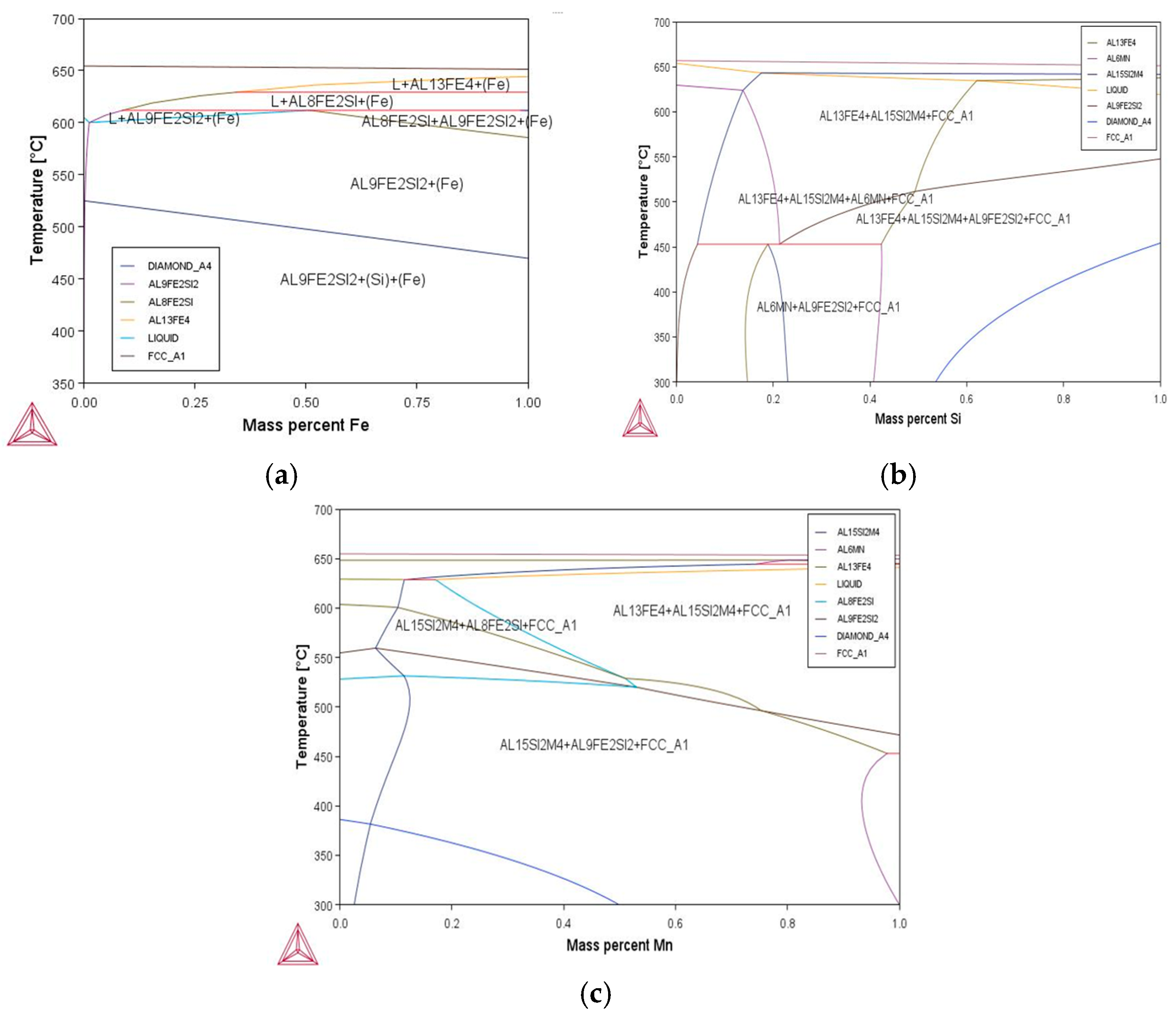
The considered calculations (Figure 1) made it possible to determine the phase composition of the alloys depending on the concentration of iron and silicon, as well as on the temperature, which made it possible to predict the formation of various phases and their distribution in the alloy. These data can be used to optimize the composition and conditions of heat treatment to improve the mechanical and operational characteristics of the alloys, such as strength, ductility, and corrosion resistance. Modeling phase diagrams showed that increasing the iron content contributes to the formation of more stable Al3Fe phases, which increases the strength characteristics but also reduces the material ductility. The addition of silicon promotes the formation of AlFeSi phases, which improve the distribution of secondary phases and also increase corrosion resistance.
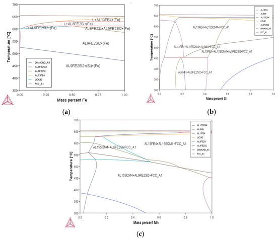
Figure 1.
Polythermal sections of the Al–Fe–Si–Mn phase diagram calculated using ThermoCalc software (TTAL8 database): (a) variation in iron content at fixed 0.5% Si and 0.6% Mn; (b) variation in silicon content at fixed 0.5% Fe and 0.6% Mn; (c) variation in manganese content at fixed 0.5% Fe and 0.5% Si. Temperature range: 400–700 °C.
Increasing conductivity in the aluminum–iron–silicon–manganese system can be caused by the formation of certain intermetallics that have high conductivity compared to pure metals or alloys. This improvement in conductivity can be caused by a specific electronic structure or bonding features of the intermetallics.
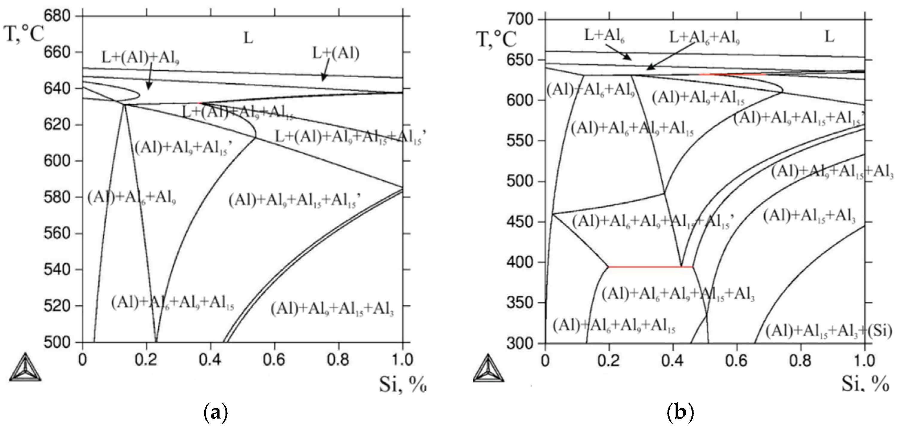
The structure of the Al–Fe–Mn–Si system is still a subject of debate. The phase diagram of this system is shown in Figure 2. The basis of the discussion is the presence or absence of a four-fold phase. Previously, it was believed that there was a continuous series of solid solutions between the Al8Fe2Si and Al15Mn3Si2 compounds [17]. Later, this concept was reduced to the fact that those compounds had different crystal structures: hexagonal and cubic, respectively.
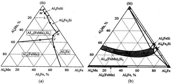
Figure 2.
Calculated phase diagram of the Al–Fe–Mn–Si system based on data from [17]: (a) liquidus boundary regions; (b) phase distribution in the solid state. Phase labels are positioned consistently across both diagrams for visual comparison.
The Al15Mn3Si2 compound is based on a large solid solution region extending to the Al–Fe–Si boundary. In this diagram variant, manganese is replaced by iron in a ternary compound of up to 31% Fe, 1.5% Mn, 8% Si, and in a wider homogeneity region, Al15(FeMn)3Si2 is interpreted as a four-fold phase assembly. The distribution of these phase regions and the possible transformation of Al15(FeMn)3Si2 into an invariant form at concentrations of up to 12% Si, 1% Fe, and 2% Mn are given in Table 1.

Table 1.
Invariant five-phase reactions in the Al–Fe–Mn–Si system [17].
It was found that alloys containing 10–14% Si, 0–1% Fe, and 0–4% Mn contain a four-fold compound Al16(FeMn)4Si3-Si, which leads to the formation of a quasitron section of Al16(FeMn)4Si3 [17]. On both sides of this section, two second-order systems are formed: Al-Al16(FeMn)4Si3-Al5FeSi-Si (adjacent to the Al–Fe–Si boundary). In addition, one more second-order system can be distinguished, which is below 596 °C: Al5FeSi-Al4FeSi2-Al16(FeMn)4Si3-Si.
According to [18], in alloys containing 10–14% Si, non-variant reactions occur, as shown in Table 2.
Table 2.
Non-variant reactions in the Al–Fe–Mn–Si system [3].
The combined effect of iron and silicon at 0.6% Mn shows that at 0.5% Si with 0.5% Fe and at 0.5% Si with 0.8% Fe, primary crystals of the Al6(FeMn) phase must inevitably form, but the iron content of less than ~0.03% leads to the formation of the Al9Fe phase (Figure 3). Due to the low solubility of Fe in (Al), the Al6(FeMn) phase is mainly of crystallization origin. The consequence of this is decreasing the Mn concentration in (Al) in the cast state and decreasing the amount of Al6Mn dispersoids formed during annealing [18,19,20,21,22,23].
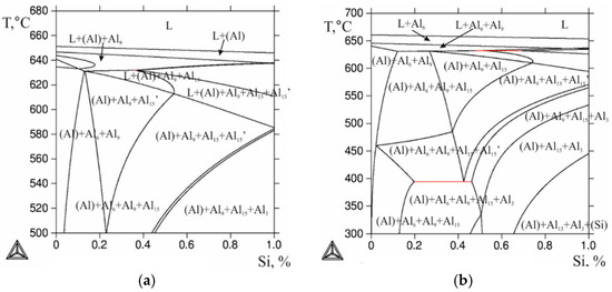
Figure 3.
Polythermal sections of the Al–Fe–Mn–Si system diagrams calculated using ThermoCalc software: (a) alloy with 0.5% Si, 0.5% Fe and 0.6% Mn; (b) alloy with 0.5% Si, 0.8% Fe and 0.6% Mn. Phase labels: A6–Al6(FeMn); A9–Al9Fe; A15–Al15(Fe,Mn)3Si2.
At a sufficient silicon concentration (over 0.5%), at 0.8% Fe and 0.6% Mn, primary crystals of the Al15(Fe,Mn)2Si3 phase can form, and this can be seen in Figure 3.
These intermetallic compounds contribute to improved electrical performance due to their specific crystal lattice and strong metallic bonding between aluminum and iron atoms. Their structure facilitates efficient electron transport, which enhances the overall conductivity of the alloy.
Phases such as AlSi (e.g., AlSi2) may enhance electrical behavior due to their characteristic electronic structure. Aluminum silicides can facilitate more efficient electron transport, thereby contributing to favorable conductivity in the alloy.
Iron silicides such as FeSi may contribute to electrical performance in high-silicon alloys. The presence of silicon in these compounds influences the electronic structure, as iron silicides typically exhibit metallic-type conductivity.
Intermetallics such as FeMn3 and other Fe–Mn compounds can also influence electrical behavior. Manganese, in turn, may enhance charge transport in iron-rich alloys by modifying the electronic structure and increasing the electron density.
There are also intermetallics such as AlMn2 that can affect conductivity. These phases can have their own characteristics that contribute to improved conductivity due to the features of their crystal structure and composition.
Thus, increasing conductivity in this system can be associated with the formation of intermetallics such as AlFe, AlSi, FeSi, AlMn2 and others, which have a certain structure and contribute to better electron movement through the material. It is important to note that this improvement in conductivity depends on the content of each element in the alloy and on the temperature, since phase transformations and the degree of alloying can significantly change the electrophysical properties of the material.
Calculations indicate that achieving optimal mechanical characteristics requires taking into account the percentage content of iron, silicon, and manganese in order to avoid the formation of unfavorable phases such as Al3Fe and AlFeSi in excessive quantities, which can lead to deterioration in ductility and decreasing impact toughness. The balanced content of these elements promotes the formation of stable and uniformly distributed phases, which is expected to improve structural stability and corrosion resistance, making the alloy potentially more suitable for industrial applications.
In addition, changes in phase boundaries with changing cooling conditions were studied, which is important for controlling the alloy structure after heat treatment. Modeling phase diagrams taking into account the cooling rate made it possible to predict how the phases will be distributed in the alloy, as well as to indicate the optimal conditions for the formation of the desired structural elements.
The evaluation of phase transformations in aluminum Al–Fe–Si–Mn alloys is an important step in predicting their structure and properties. The ThermoCalc software package enables the detailed modeling of these processes, accounting for changes in temperature and composition, which makes it possible to analyze in detail the behavior of the phases under various process conditions.
Modeling phase transformations with changes in temperature showed that with increasing the temperature, significant changes in the composition and morphology of the phases occur. In the Al–Fe–Si–Mn system, such phases as Al3Fe, AlFeSi, Al6Mn, and AlMn2 have different temperatures of formation and solubility, which must be taken into account when developing alloys with the required properties.
At temperatures below 400 °C, such primary phases as Al3Fe and AlFeSi begin to form in the alloy, which are stable at low temperatures.
At approximately 600 °C, the Al3Fe phase begins to decompose into smaller crystals, which changes the mechanical properties of the alloy. At this time, the AlFeSi phase also forms, which stabilizes at high temperatures, improving corrosion resistance.
At temperatures above 700 °C, such phases as Al3Fe completely dissolve in the liquid metal, which makes the alloys easier to cast and process but can also lead to a loss of the original strength characteristics.
Changing the content of Fe, Si, and Mn components also affects phase transformations. Modeling has shown the following:
- Increasing the iron content promotes the early formation of the Al3Fe phase, which increases the strength of the alloy but reduces its ductility. In this case, the phase boundary between Al3Fe and the liquid solution shifts towards lower temperatures.
- Increasing the silicon content leads to a more significant formation of the AlFeSi phase, which stabilizes the alloy structure and promotes a more uniform distribution of secondary phases, which reduces the risk of forming large brittle intermetallics.
- The balanced silicon and iron content avoids the excessive formation of brittle phases, maintaining optimal mechanical properties at higher temperatures.
The results of phase transformation modeling can be used to optimize heat treatment, including the selection of temperature conditions for melting, annealing, quenching and subsequent cooling. This allows minimizing the formation of undesirable phases, such as large intermetallic compounds, and ensuring a structure with the required mechanical properties, such as high strength, ductility, and corrosion resistance. This approach helps improve the technology of alloy production and their adaptation to specific operating conditions. Thus, the assessment of phase transformations with changes in temperature and composition is the key to managing the properties of Al–Fe–Si–Mn aluminum alloys. The obtained results made it possible to develop recommendations for controlling the composition and thermal conditions to achieve optimal mechanical properties of the alloys.
To confirm the obtained results using ThermoCalc software, the main objects of the study were aluminum alloy sheets containing up to 1% Fe 0.5% Si 0.6% Mn. Experimental alloys (Table 3) were prepared in an electric resistance furnace in a graphite–chamotte crucible made of primary aluminum of grade A7E (SSThe c11069-2001). Flat ingots with dimensions of 40 mm × 120 mm × 200 mm were obtained by casting into a graphite mold.
Table 3.
Chemical composition of experimental alloys.
Annealing was carried out in an SNOL electric furnace in stepwise modes at 400–650 °C with a 50 °C step and a holding time of 3 h, as summarized in Table 4.
Table 4.
Heat treatment modes for experimental samples of the Al–Fe–Si–Mn system.
- Note on designations:
- Designations such as T400–T650 correspond to stepwise annealing temperature ranges (e.g., T500 indicates annealing from 450 to 500 °C).
- HP refers to cold-rolled sheets, S refers to hot-rolled sheets, and L indicates as-cast ingots.
- Numbers following the letters indicate the final annealing temperature or processing condition. For example, HP450 refers to a cold-rolled sheet annealed at 450 °C.
- Rolling procedures:
- After casting, the ingots were subjected to two types of deformation: hot rolling and cold rolling. Hot rolling was performed at a temperature of approximately 450–500 °C to reduce the thickness of the ingots. Cold rolling was carried out at room temperature after intermediate annealing, achieving a final thickness reduction of approximately 80%. Intermediate annealing steps were performed between passes to relieve internal stresses and refine the microstructure.
The microstructure of the samples was studied using a Magus Metal VD700 BD LCD optical microscope (Guangzhou Liss Optical Instrument Co., Ltd., Guangzhou, China) and a TESCAN VEGA 3 scanning electron microscope (TESCAN GROUP, Brno, Czech Republic). Both mechanical and electrolytic polishing were used to prepare the sections, which were carried out at the voltage of 12 V in an electrolyte containing 6 parts C2H5OH, 1 part HClO4 and 1 part glycerol.
3. Results and Discussion
It can be seen from the metallographic analysis of the samples that the assumption about the formation of the FeSi, FeMn3, and Al15Mn3Si2 phases was confirmed. There are inclusions of the phase (Al, Fe, Si) in the form of skeletal fragments or veins along the boundaries of dendritic cells (Al). During the rolling process, the equiaxed grain structure was transformed into a fibrous one, and the inclusions of the iron-containing phase also stretched out.
Annealing did not cause significant microstructural changes observable via optical microscopy; therefore, structural and phase transformations during the annealing process were assessed by changes in resistivity and hardness, as well as by the calculation results.
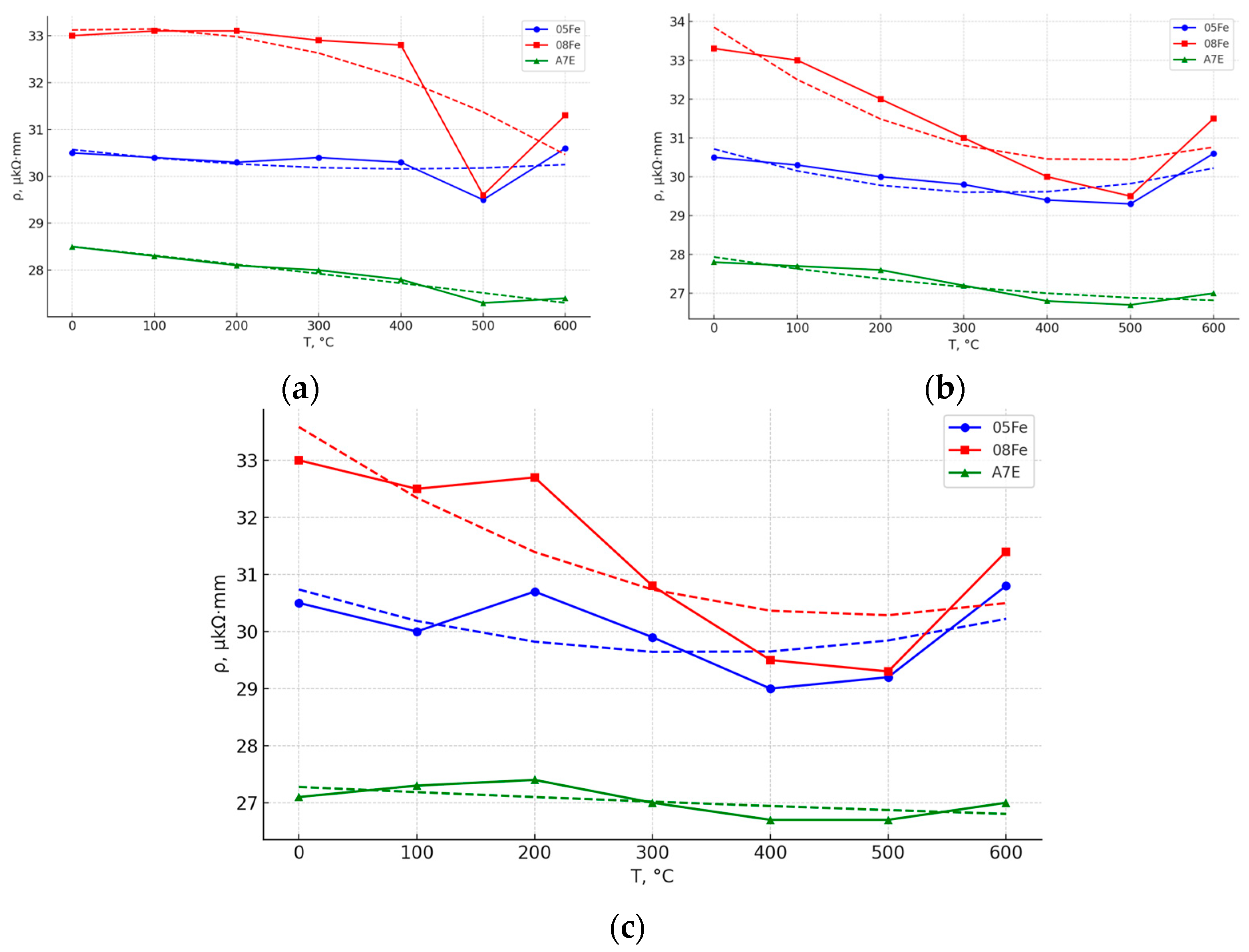
For each mode, specific electrical conductivity was measured, which was determined by the eddy current method on a VE-26NP device, and then they were converted into specific electrical resistance. As follows from the dependences shown in Figure 4a, when using multi-stage annealing, the minimum values of resistivity of the experimental alloys are achieved at 450–500 °C, which can be explained by the maximum decrease in the concentration of iron in the aluminum solid solution. It is important to note that in this state, the experimental alloys of 0.5% Fe and 0.8% Fe have the same resistivity values. It follows that the effect of L12 phase nanoparticles on electrical resistance is much less.
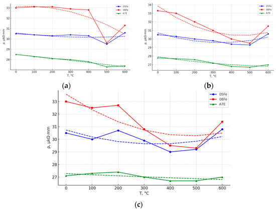
Figure 4.
Effect of the final annealing temperature on the specific electrical resistivity of the experimental alloys: (a) ingots; (b) cold-rolled sheets; and (c) hot-rolled sheets. All graphs are presented in a uniform style; ρ is in μΩ·mm and temperature in °C.
With increasing temperature, increasing resistivity is observed for both ingots (Figure 4a) and sheets (Figure 4b,c), which is obviously caused by increasing the concentration value according to the solvus of the Al–Fe diagram. The difference in resistivity of the alloys of 0.5% Fe and 0.8% Fe again begins to increase, reaching the maximum at 650 °C.
Analyzing the obtained results, it can be concluded that the decomposition of the (Al) solid solution occurs at the slowest rate in the ingots and at the fastest rate in the cold-rolled sheets. In particular, for the alloy containing 0.5 wt.% Fe, the minimum resistivity values are observed to be 29.7 × 10⁻⁹ Ω·m for the ingot annealed under the T500 condition and 28.7 × 10⁻⁹ Ω·m for the cold-rolled sheet in the HP450 condition.
Obviously, as the annealing holding time increases, the difference between these values is expected to decrease.
In addition to the detailed results for 0.5Fe and 0.8Fe alloys, the alloys with lower iron contents—0.2Fe, 0.3Fe, and 0.4Fe—were also investigated. These compositions demonstrated expected trends, with slightly lower hardness and electrical resistivity compared to the higher-iron alloys. The 0.2Fe and 0.3Fe alloys, in particular, showed reduced volume fractions of intermetallic phases such as Al3Fe, resulting in more ductile microstructures. While the structural differences were less pronounced under light microscopy, measurements confirmed that electrical resistivity decreased gradually from 0.2Fe to 0.4Fe before reaching minimum values in the 0.5Fe alloy. These results confirm the transitional behavior across the series and highlight the continuous effect of iron content on physical properties.
The microstructures of the alloys are shown in Figure 5, Figure 6, Figure 7 and Figure 8. In the 0.5Fe alloy, veins of the Al3Fe phase are visible, and in the 0.8Fe alloy, particles of the Al15(Fe,Mn)3Si2 phase are visible. The confirmation was obtained from microstructural analysis, and the morphology indicates the presence of eutectic structures. During intermediate annealing, phase separation and microparticles can be clearly seen. There is an increase in dendritic cells (Al).

Figure 5.
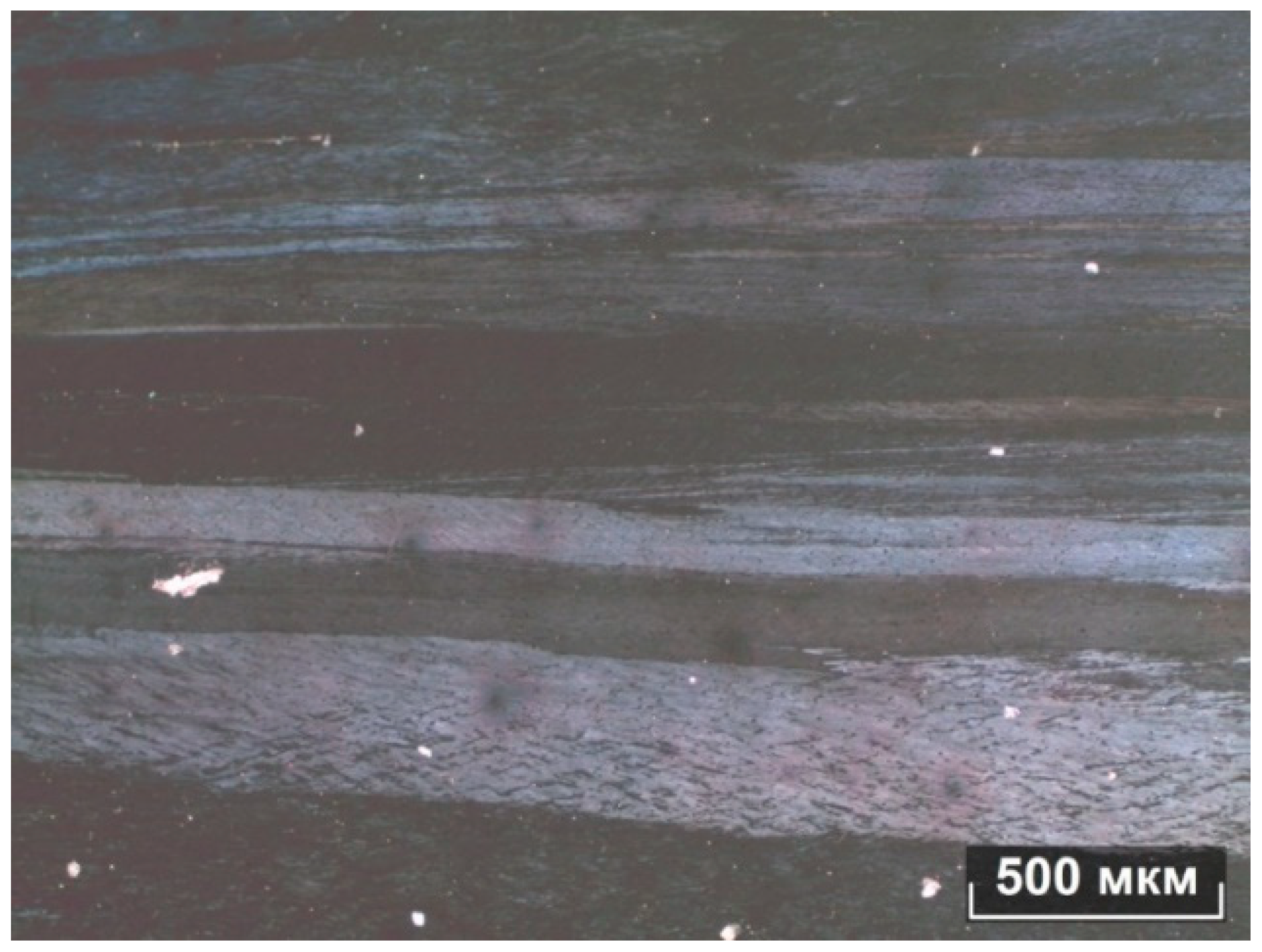
Microstructure of Al–0.5% Fe alloy after hot rolling with intermediate annealing at 550 °C: (a) optical microscopy (OM), etched section, scale bar—100 μm; (b) scanning electron microscopy (SEM), etched surface, showing elongated Al3Fe intermetallic phases along deformation lines, scale bar—500 μm.

Figure 6.
Optical micrograph (OM) of Al–0.8% Fe alloy after hot rolling with intermediate annealing at 650 °C. The structure shows equiaxed grains with moderate size distribution. Scale bar—500 μm.

Figure 7.
Optical micrograph (OM) of Al–0.8% Fe alloy after hot rolling without intermediate annealing (condition S300). Elongated intermetallic phase regions are visible in the dendritic structure. Scale bar—500 μm.
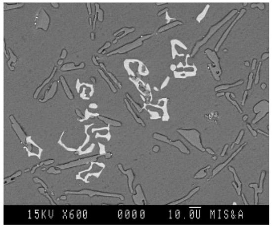
Figure 8.
SEM micrograph of an Al–Si–Fe–Mn alloy with 8% Si, 0.7% Fe, and 0.3% Mn, showing skeletal Al15(Fe,Mn)3Si2 intermetallics; 15 kV, 600×, scale bar—10 μm.
The addition of manganese is believed to reduce the detrimental effects of iron by promoting the formation of complex intermetallics such as the Al15(Fe,Mn)3Si2 phase, which exhibits skeletal morphology, as observed in Figure 8. While the morphology is consistent with literature reports, further confirmation using EDS or XRD would be necessary to verify the exact phase composition (Figure 8) [24].
The results obtained can be used to optimize the composition of aluminum alloys, especially in cases where a combination of high strength and resistance to external influences is required. Thermodynamic modeling with ThermoCalc can significantly reduce the development time of new alloys and improve their manufacturability, which is especially important for high-performance engineering applications where precise material matching is essential.
4. Conclusions
The ThermoCalc software has proven to be a reliable and effective tool for the thermodynamic modeling of phase compositions in aluminum alloys, particularly within the Al–Fe–Si–Mn system. Its use enables the prediction of phase equilibria, the assessment of alloying effects, and the optimization of processing parameters. This approach significantly reduces the time and cost required for alloy development, providing a solid foundation for integrating simulation and experimental techniques in materials science.
The modeling of phase diagrams, combined with experimental validation, confirmed the formation of key intermetallic compounds such as Al3Fe, AlFeSi, and Al15(Fe,Mn)3Si2, which play a decisive role in tuning the mechanical and electrical properties of the alloys. The presence of manganese and silicon was shown to neutralize the negative effects of iron and to promote a more uniform phase distribution, improving the structural integrity of the material.
The analysis of the iron, silicon, and manganese content demonstrated that the optimal ratio—up to 0.8% Fe, 0.5% Si, and 0.6% Mn—leads to the development of aluminum alloys with a favorable combination of high strength, ductility, corrosion resistance, and electrical conductivity. Furthermore, it was found that heat treatment in the temperature range of 500–550 °C ensures a stable microstructure with improved thermal resistance and reduced electrical resistivity.
These findings provide valuable insights into the design of conductive aluminum alloys intended for engineering, structural, and electrical applications. The integration of thermodynamic modeling and controlled alloy processing opens new opportunities for creating advanced materials with predictable and optimized properties.
Author Contributions
Conceptualization: B.S. and A.D., Methodology: D.A. and A.I.; Formal Analysis: A.D. and investigation T.S.; Writing—Original Draft Preparation: T.S. and D.A. Funding Acquisition: A.I. and B.S. All authors have read and agreed to the published version of the manuscript.
Funding
The work was carried out within the framework of the implementation of the IRN Program BR21882240 “Developing a quasi high-entropy alloy using Kazakhstan raw materials and the technology of producing precision parts based on it” (agreement with the Committee of Science of the Ministry of Education and Science of the Republic of Kazakhstan No. 378-PTsF-23-25 dated 15 November 2023), funded by the Ministry of Science and Higher Education of the Republic of Kazakhstan.
Data Availability Statement
The original contributions presented in this study are included in the article. Further inquiries can be directed to the corresponding author.
Conflicts of Interest
The authors declare no conflicts of interest.
References
- Online Electrician. A Power Transmission Line is a Wired or Cable Power Transmission Line. Available online: http://onlineelektrik.ru/eprovodka/cabeli/lep-eto-provodnaya-ili-kabelnaya-liniya-peredachielektroenergii.html (accessed on 17 December 2024).
- Studopedia. Principles of Constructive Execution of Power Transmission Lines. Available online: https://studopedia.su/9_48994_vozdushnie-linii-elektroperedachi.html (accessed on 17 December 2024).
- RusCable. Uninsulated Wires of Overhead Power Transmission Lines: The Problem of Choice. Available online: http://www.ruscable.ru/article/neizolirovanye_provoda_lep_problema_vybora/ (accessed on 17 December 2024).
- Medvedev, A.E.; Zhukova, O.O.; Fedotova, D.D.; Murashkin, M.Y. Mechanical properties, electrical conductivity, and thermal stability of wire from Al–Fe alloys obtained by casting into an electromagnetic mold. Front. Mater. Technol. 2022, 3-1, 96–105. [Google Scholar] [CrossRef]
- Korotkova, N.O.; Belov, N.A.; Timofeev, V.N.; Motkov, M.M.; Cherkasov, S.O. Influence of Heat Treatment on the Structure and Properties of an Al-7% REM Conductive Aluminum Alloy Casted in an Electromagnetic Crystallizer. Phys. Met. Metallogr. 2020, 121, 173–179. [Google Scholar] [CrossRef]
- Ding, H.; Xiao, Y.; Bian, Z.; Wu, Y.; Yang, H.; Wang, H.; Wang, H. Design, microstructure, and thermal stability of a novel heat-resistant Al-Fe-Ni alloy manufactured by selective laser melting. J. Alloys Compd. 2021, 885, 160949. [Google Scholar] [CrossRef]
- Bian, Z.; Dai, S.; Wu, L.; Chen, Z.; Wang, M.; Chen, D.; Wang, H. Thermal stability of Al–Fe–Ni alloy at high temperatures. J. Mater. Res. Technol. 2019, 8, 2538–2548. [Google Scholar] [CrossRef]
- Haga, T.; Takahashi, K.; Ikawa, M.; Watari, H. A vertical-type twin roll caster for aluminum alloy strips. J. Mater. Process. Technol. 2003, 140, 610–615. [Google Scholar] [CrossRef]
- Azimaee, H.; Sarfaraz, M.; Mirjalili, M.; Aminian, K. Effect of silicon and manganese on the kinetics and morphology of the intermetallic layer growth during hot-dip aluminizing. Surf. Coat. Technol. 2019, 357, 483–496. [Google Scholar] [CrossRef]
- Andreyachshenko, V.; Bartenev, I.; Malashkevichute-Brillant, Y. Synthesis of an aluminum alloy rich in iron and silicon by surfacing with a consumable electrode. Acta Metall. Slovaca 2024, 30, 133–136. [Google Scholar] [CrossRef]
- Belov, N.A.; Cherkasov, S.O.; Korotkova, N.O.; Yakovleva, A.O.; Tsydenov, K.A. Effect of Iron and Silicon on the Phase Composition and Microstructure of the Al–2% Cu–2% Mn (wt. %) Cold Rolled Alloy. Phys. Metals Metallogr. 2021, 122, 1095–1102. [Google Scholar] [CrossRef]
- Kralik, R.; Krivska, B.; Bajtosova, L.; Šlapakova, M.; Cieslar, M. Homogenization of twin-roll cast AA8079 aluminum alloy studied by in-situ TEM. Trans. Nonferrous Met. Soc. China 2022, 32, 2138–2149. [Google Scholar] [CrossRef]
- Avdulov, A.A.; Usynina, G.P.; Sergeev, N.V.; Gudkov, I.S. Distinctive features of the structure and properties of long-length ingots of small cross-section made of aluminum alloys cast in an electromagnetic mold. Non-Ferr. Met. 2017, 7, 73–77. [Google Scholar] [CrossRef]
- Belov, N.A. The Phase Composition of Aluminum Alloys; MISiS Publishing House: Moscow, Russia, 2009; p. 392. [Google Scholar]
- Vorontsova, L.A. Aluminum and Aluminum Alloys in Electrical Products; Energiya: Moscow, Russia, 1971; p. 224. [Google Scholar]
- Mondolfo, L.F. Structure and Properties of Aluminum Alloys; Elsevier Ltd.: London, UK, 1979; p. 640. [Google Scholar]
- Grigoryev, V.G.; Smirnov, I.V. Thermodynamics of Aluminum Alloys. Mater. Technol. 2021, 36, 326. [Google Scholar]
- Toleuova, A.R.; Dostayeva, A.M.; Zharkevich, O.M.; Adilkanovva, M.A. Calculating and experimental studying phase transformations in the Al-Zr-Fe-Si system alloys. Metalurgija 2020, 59, 543–546. [Google Scholar]
- Kulikov, V.Y.; Aubakirov, D.R.; Kvon, S.S.; Dostaeva, A.M.; Shcherbakova, E.P. Use of Wear-Resistant Materials in the Kazakhstan Metallurgical Industry. Metallurgist 2019, 62, 1068–1072. [Google Scholar] [CrossRef]
- Batessova, F.; Omirbay, R.; Sattarova, G.; Zholmagambetov, N.; Zholmagambetov, S.; Dostayeva, A.; Suleimenov, N.; Medeubayev, N. Reducing industrial noise by the use of damping alloys when manufacturing mining equipment parts. Heliyon 2023, 9, e17152. [Google Scholar] [CrossRef] [PubMed]
- Aubakirov, D.; Issagulov, A.; Akberdin, A.; Kvon, S.; Kulikov, V.; Arinova, S.; Dostaeva, A.; Chsherbakova, Y.; Sarkenov, B.; Narembekova, A. Influence of boron- and barium-containing modifiers on the structure of low-chromium cast iron. Heliyon 2022, 8, e11496. [Google Scholar] [CrossRef] [PubMed]
- Dostayeva, A.M.; Yerahtina, I.I.; Zholmagambetov, N.R.; Medeubayev, N.A.; Zholmagambetov, S.R. Investigation of aluminum-titanium alloys production and labor safety in metal smelting process. Metalurgija 2021, 60, 403–406. [Google Scholar]
- Kovalyova, T.; Yeremin, E.; Arinova, S.; Medvedeva, I.; Dostayeva, A. Enhancing surface roughness of castings when sand-resin mold casting. Metalurgija 2017, 56, 135–138. [Google Scholar]
- Belov, N.A.; Dostayeva, A.M.; Shurkin, P.K.; Korotkova, N.O.; Yakovlev, A.A. Effect of annealing on electrical resistance and hardness of hot-rolled sheets of aluminum alloys containing up to 0.5% Zr. Bull. Non-Ferr. Metall. Univ. M. NUST MISiS 2016, 3, 48–55. [Google Scholar]


Disclaimer/Publisher’s Note: The statements, opinions and data contained in all publications are solely those of the individual author(s) and contributor(s) and not of MDPI and/or the editor(s). MDPI and/or the editor(s) disclaim responsibility for any injury to people or property resulting from any ideas, methods, instructions or products referred to in the content. |
© 2025 by the authors. Licensee MDPI, Basel, Switzerland. This article is an open access article distributed under the terms and conditions of the Creative Commons Attribution (CC BY) license (https://creativecommons.org/licenses/by/4.0/).