Article

Using Molecular Dynamic Simulation to Understand the Deformation Mechanism in Cu, Ni, and Equimolar Cu-Ni Polycrystalline Alloys

Metallurgy Department, Faculty of Engineering, University of Mons, 20, Place du Parc, 7000 Mons, Belgium
*
Author to whom correspondence should be addressed.
Alloys 2023, 2(1), 77-88; https://doi.org/10.3390/alloys2010005
Submission received: 11 December 2022 / Revised: 19 February 2023 / Accepted: 6 March 2023 / Published: 15 March 2023
(This article belongs to the Collection Feature Paper Collection of Advanced Research on Alloys)

Abstract

:
The grain boundaries and dislocations play an important role in understanding the deformation behavior in polycrystalline materials. In this paper, the deformation mechanism of Cu, Ni, and equimolar Cu-Ni alloy was investigated using molecular dynamic simulation. The interaction between dislocations and grain boundary motion during the deformation was monitored using the dislocation extraction algorithm. Moreover, the effect of stacking fault formation and atomic band structure on the deformation behavior was discussed. Results indicate that dislocations nucleate around the grain boundary in copper, the deformation in nickel changes from planar slip bands to wavy bands, and high density of dislocation accumulation as well as numerous kink and jog formations were observed for the equimolar Cu-Ni alloy. The highest density of the Shockley dislocation and stacking faults was formed in the equimolar Cu-Ni alloy which results in the appearance of a huge gliding stage in the stress–strain curve. The grain boundaries act as a sinking source for vacancy annihilation in Ni and Cu; however, this effect was not observed in an equimolar Cu-Ni alloy. Finally, radial distribution function was used to evaluate atom segregation in grain boundaries.

1. Introduction

The mechanical properties of polycrystalline metals depend on their microstructure such as grain boundaries, dislocation interactions and cross slip behavior during plastic deformation [1,2,3]. Conducting experiments at the nanometer scale to understand the deformation behavior of polycrystals can be time-consuming, expensive, and requires complex equipment. For this reason, the use of molecular dynamics simulations for better understanding of the deformation mechanisms at the nanoscale is crucial.
Conventionally, on the study of the deformation behavior in alloys, it has been reported based on the experimental results that the solute atoms do not dissolve perfectly into the matrix and create short-range disorder structure. Presence of short-range disorder atoms in alloys or metals makes the cross slip of dislocations difficult and results in strain hardening [4,5]. However, performing various simulations on alloys, specifically nanocrystalline ones, and investigating the mechanism of their deformation behavior, has rejected this theory and offered a new perspective on the science of investigating the alloy deformation mechanism. The results of these studies show that when the grain size is larger than 15 nm, the plastic deformation is based on the traditional Fleischer theory known as alloy pinning effect. However, when the grain size reduces below 15 nm, grain boundary sliding and rotation as well as stacking fault formation become the main deformation mechanisms [6,7].
Investigating the deformation behavior of the Cu-Pb alloy, researchers showed that solute atoms quickly stiffen the lattice and yield strength of the alloy. In fact, having stiffer lattice due to the presence of solute atoms makes it more difficult for two grains to deform and rotate past each other [6]. On the other hand, molecular dynamics simulation of the Cu-Sb alloy shows that the formation of unstable stacking faults near the solute atoms leads to the softening of the alloy [8,9]. It has also been reported that the addition of aluminum as a solid solution in the copper structure makes the cross slip during the deformation easier, which causes the work hardening to be dependent on the strain rate [10,11]. In the study of copper alloy deformation, Szczerba et al. [12] emphasized the dual role of material stacking fault energy on the activation of twinning and twinning stress of face-centered cubic (FCC) materials.
Cu-Ni alloys are copper-based solid solutions that are widely used in many industries including automobile, power generation, marine, jet engine compressors, and aerospace industry [13]. In this alloy, both constituents—Cu and Ni—form an isomorphous system without phase precipitation, where the stacking fault energy changes by a factor of three between pure Cu and Ni [14]. The distribution of solute Ni atoms into the Cu matrix impedes the motion of edge dislocations, researchers’ results have shown that the dislocation velocity decreases with increasing Ni content [15]. In fact, with high short-range ordering of Cu-Ni clusters in the Cu, the plastic deformation in the adjacent glide planes is restricted, which prevents cross slip [16]. In the investigation of the effect of nanoindentation on the deformation mechanism of Cu-Ni alloy, Vu et al. have reported that the dislocation motion and rotation of grain boundaries play a significant role in the deformation behavior of polycrystal alloy [17]. In fact, sliding and twisting of grain boundaries as well as the fusion of grains results in preventing the spread of strain and stress which considerably increases the alloy strength [18]. Shinde et al. in the study of the effect of indentation on dislocation interaction of single crystal Cu-Ni alloy have reported that the equimolar Cu-Ni has a 43% higher hardness value than pure copper. Moreover, the total length of dislocations for equimolar Cu-Ni is 5% less than that of copper [19]. The formation and interaction of dislocations such as Perfect, Shockley, Hirth, and stair-rode is the main reason for the improvement of the tensile stress in Cu-Ni alloy [20].
Various deformation mechanisms have been already reported for copper alloys using molecular dynamic simulation. However, the literature shows there are limited studies about dislocation interactions around the grain boundaries during deformation. Therefore, in this work, the deformation behavior of the copper (Cu), nickel (Ni), and equimolar Cu-Ni alloy (the most commonly used and easily accessible Cu-Ni alloy [19]) polycrystals containing grains with different orientations have been investigated by developing LAMMPS simulation code. The deformation mechanism of the polycrystals has been discussed by tracking the motion of dislocations at the grain boundaries to assess the differences and similarities of deformation behavior of equimolar Cu-Ni alloy with pure copper and nickel. On the other hand, the formation of voids, stacking faults, and the structure of atom clusters among the grain boundary atoms were further evaluated.

2. Simulation Method and Conditions

2.1. Building Polycrystals Structure

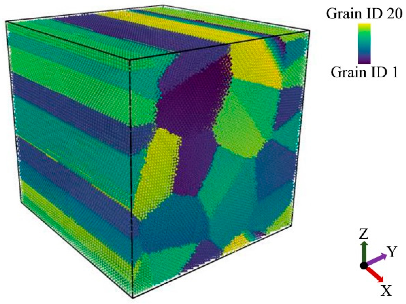
The polycrystalline structures of Cu, Ni, and equimolar Cu-Ni alloy were built in a 200 × 200 × 200 Å cells containing 20 grains with different sizes and orientations (Figure 1) by Atomsk software using the Voronoi tesselation method (VTM) [21]. The first grain was positioned at the origin (0,0,0) and oriented at X = [100], Y = [010], Z = [001] direction. For creating the other grains with various orientation, all the grains were set to have [001] axis aligned with the Z direction, and each grain was rotated randomly around the Z axis. The grain boundaries were built by inserting 1/2 <110> perfect dislocation between each grain with different orientations.
The grains were elongated towards the x direction to be able to track the dislocation motions more easily when the shear stress was applied in this direction (Figure 2). Each polycrystals cell was divided into three parts from bottom to top: fixed atoms, thermal control atoms and Newtonian atoms. The fixed atoms consist of 2 layers of atoms, which are held in the perfect lattice positions to prevent the cells from moving during the deformation process. The intermediate thermal control atoms consist of 6 layers of atoms, which are recalibrated every 5 timestep by the Berendsen thermostat to maintain the system temperature within a constant temperature range. The other atoms which are mainly the atoms in the middle section of the cell are Newtonian atoms which are set thick enough to ensure that they could move easily during deformation.

2.2. Simulation of the Deformation

The molecular dynamic simulation of the deformation process was carried out using an open code Large scale Atomic/Molecular Massively Parallel Simulator (LAMMPS) [22] under NVT thermodynamic conditions for approximately 100 ps. The time step was set to 1 fs and Leap Frog algorithms were used to determine the velocities at half-integer time steps to compute the new positions of atoms [23].
The atomic interactions were defined using embedded–atom–method (EAM) potential [24]. The simulation cell was divided into three sections; the atoms in the upper and lower sections were fixed while the atoms in the middle section of the cell could move easily during deformation. The energy of the system was minimized before the deformation process. A deformation speed of 0.05 m/s was applied in the upper section as a shear stress along the Y axis.
The dislocation extraction algorithm (DXA) and the common neighbor analysis (CNA) technique are adopted to track the motion of grain boundaries, dislocation interaction, dislocation length, and stacking faults (SFs) formation. The variations of structural parameters and atomic potential energy in the system were visualized by the Open Visualization Tool (OVITO) [25,26]. The strain–stress curves were plotted during the simulation, the radial distribution function (RDF) was used to analyze the structure of atom clusters among the grain boundary atoms, and finally the Wigner–Seitz analysis was used to evaluate the formation of vacancies during the deformation.

3. Results and Discussion

3.1. Nucleation and Growth of Dislocations

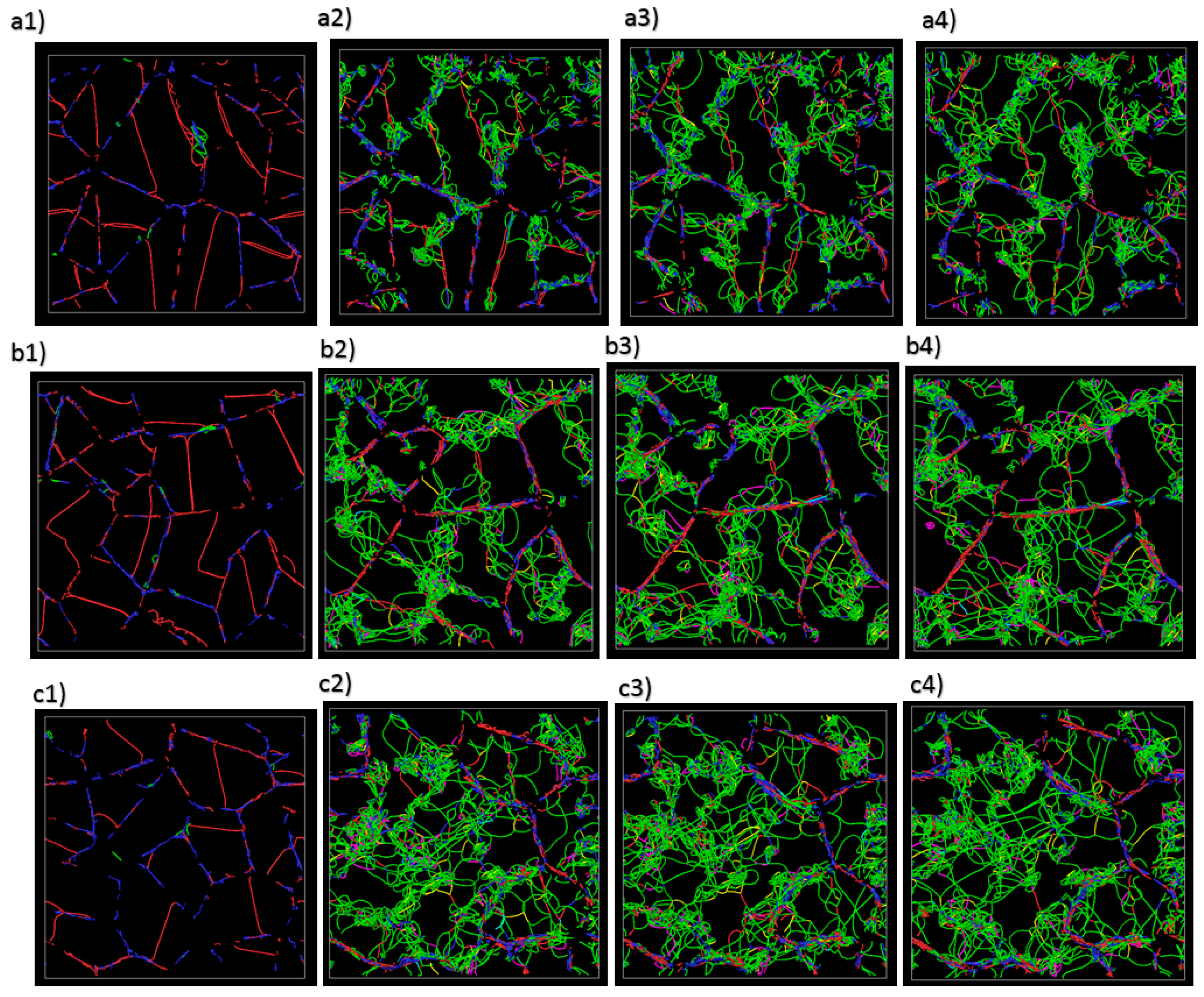
Figure 3 shows the snapshot simulation images resulting from the interaction and movement of dislocations due to the applied shear stress. The green lines show the Shockley dislocations and the red and blue colors show the perfect dislocations. In all three polycrystals, the dislocations nucleate from the grain boundaries. However, by increasing the simulation time, the dislocations in copper almost accumulate and interweave around the grain boundaries. In nickel, at shorter times, the dislocations are generated around the grain boundaries with higher density than copper and more bowing effects of the Shockley dislocations (shown by green color) are observed at upper times. This behavior implies the fact that the planar slip bands have been formed at the earlier stages of deformation and afterwards the deformation mechanism is followed by wavy slip bands. It is interesting to note that in smaller-sized grains, dislocations nuclei can move more easily from the grain boundary to the grain side. The stress for bowing the dislocation can be obtained from the following equation [27]:
τ c = µ b 2 π L ln ( L 10 b ) ,
where µ is the elastic modulus, b the magnitude of the Burgers vector, L is the distance between pinning points, and τ, c is the stress necessary for the dislocation to bow out. Based on this formula, the main reason for observing intense dislocation bowing effect of nickel compared to copper is nickel’s higher elastic modulus. In the equimolar Cu-Ni alloy sample at the earlier time steps, unlike in the copper and nickel, the dislocations are not accumulated around the grain boundaries. Rather, an irregular network of dislocations is observed inside the grains.
The two main processes that are involved in the dislocation cross slips are as follows: First, direct dislocation movement across the grain boundaries; second, spreading and re-nucleation of the dislocations from the remaining dislocations at grain boundaries [28]. The high accumulation of dislocation density inside the grains in equimolar Cu-Ni alloy occurs due to the formation of numerous shearing bands in different directions toward the grains. Later in the simulation, when the dislocations cross slip towards the adjacent grains, the new grain boundary acts as a barrier leading to a higher accumulation of the dislocations. In all polycrystalline structures, larger grains allow pinned dislocations to bend more easily than smaller grains, because the stress required for a dislocation pinned at both ends to propagate is proportional to the inverse of the pinned distance.
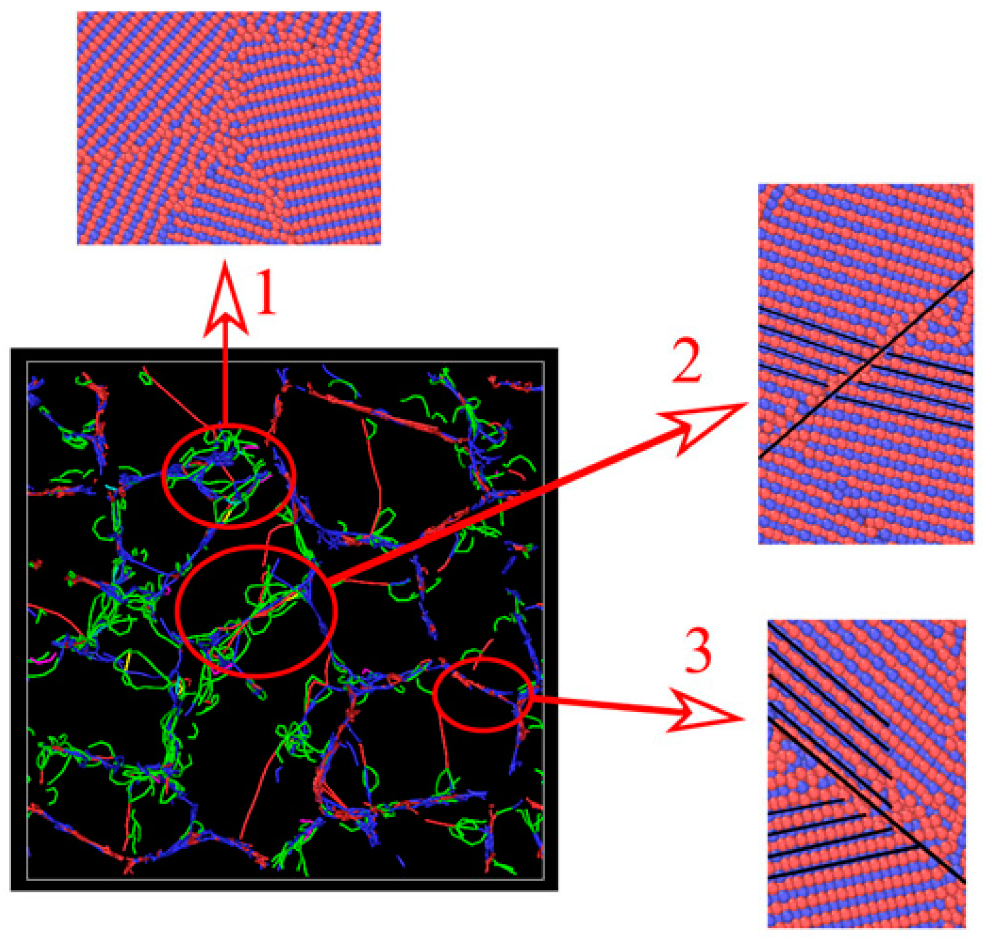
In order to understand more clearly which factors accelerate the nucleation of dislocations in equimolar Cu-Ni alloy, the image of the dislocation and atomic structure of the alloys at the earlier stage of the simulation is shown in Figure 4. Interestingly, three areas can be accounted for the main driving force of the dislocation nucleation. First are the smaller-sized grains due to the fact that the stress accumulation is more severe in smaller grains [29]. Second are triple junction points in grain boundaries (pointed by arrow 1). It has been experimentally shown that these areas are centers of high hydrostatic compressive stress which accelerates the dislocation nucleation rate [30]. Third are grain boundaries with low misorientation (pointed by arrow 2). In Figure 4, two grain boundaries with high and low crystallographic misorientation have been shown. When the misorientation between the grains is too high, no dislocations are formed (pointed by arrow 3).

3.2. Dislocation Length

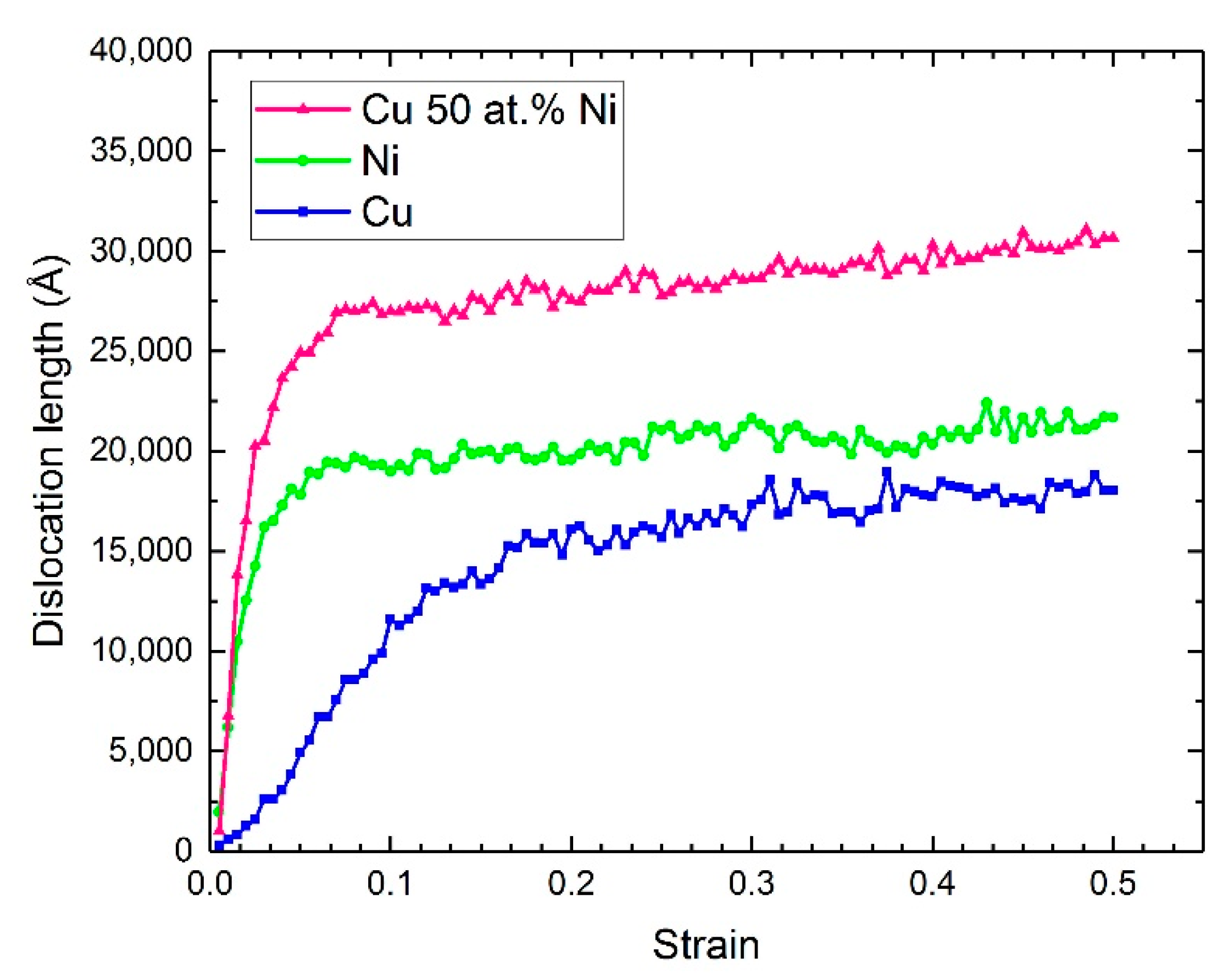
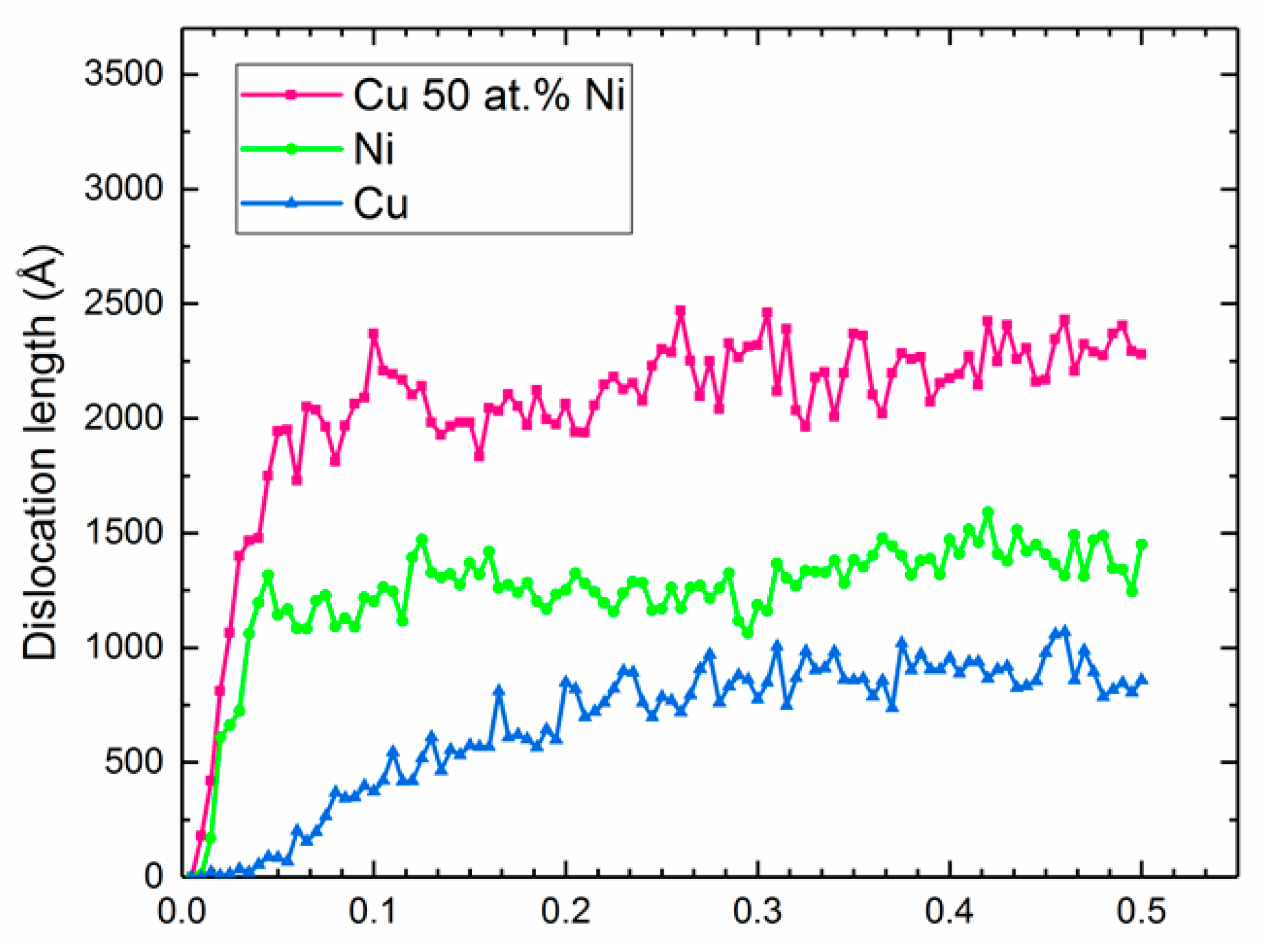
Figure 5 shows the dislocation length of the 1/6 <112> Shockley dislocations for Cu, Ni, and equimolar Cu-Ni alloy. The highest Shockley dislocation length was observed in equimolar Cu-Ni alloy, and the lowest Shockley dislocation length was observed in Cu. In the case of copper, the Shockley dislocation length increases gradually with increasing the strain and remains almost steady at strains above 0.3. In nickel, the Shockley dislocation length increases rapidly and remains steady at lower strain compared to copper. The same trend was observed in the equimolar Cu-Ni alloy, but, after the rapid increase in the Shockley dislocation length at a lower strain, the dislocation length continues to slightly increase at higher strain; however, it does so with significantly lower rate.
The existence of interstitial atoms in equimolar Cu-Ni alloy will provide barriers with various energies for the dislocation motion, therefore, as a result, dislocation does not move in one direction and spreads throughout the grains, which finally results in increasing dislocation length.
Figure 6 shows the variation on the 1/6 <110> stair-rod dislocation length which was formed in the Cu, Ni, and equimolar Cu-Ni alloy. The trend is very similar to that of the Shockley dislocation length. It means that the nucleation of the Shockley dislocation plays an important role for the formation of the stair-rod dislocation. It is worth to mention that the stair-rod is a Lomer–Cotrell dislocation at the tip of two stacking fault ribbons bordered on the other side by Shockley partials which requires a higher amount of energy for movement. It is believed that the presence of atoms of different atomic radius in equimolar Cu-Ni alloy creates lattice distortion, which can act as an obstacle for dislocations cross slip and leads to creation of more Lomer–Cotrell dislocation.
Figure 7 shows the inside view of the dislocation interactions at 100 ps for the equimolar Cu-Ni alloy. When dislocations with different slip systems are mutually parallel, they react at the intersections of slip planes belonging to different slip systems, which results in the formation of various junctions. Two main junctions are formed in the structure: Lomer lock with a Burgers vector of <110> (shown in pink) and Hirth lock with a Burgers vector of <110> (shown in yellow). The probability of Lomer lock formation is higher than that of Hirth lock. The results show that the formation of Lomer lock is more pronounced when the density of Shockley partial dislocations is higher in the structure. On the other hand, dislocation bowing also increases the possibility for formation of any kind of junctions in the structure. The junctions in the equimolar Cu-Ni alloy tie together two or more dislocations. The plastic deformation will be more difficult when a higher number of dislocations are tied together.

3.3. Stress–Stain Curve

The stress–strain curves of the Ni, Cu, and equimolar Cu-Ni alloy are shown in Figure 8. In polycrystalline copper, the shear stress increases gradually with increasing strain. The absence of steady sheer stress at high strain rates implies the fact that the dislocation density is very low and is not saturated in the structure. In polycrystalline nickel, however, after 0.2 strain, a sudden increase in the shear stress is observed before a steady state, and at 0.4 strain, the sheer stress increases gradually with a higher slope. The shear stress in the equimolar Cu-Ni alloy was higher than in both copper and nickel at higher strains. The sudden increase in the shear stress at 0.23 strain in this alloy is due to the dislocation gliding effect. It is believed that a higher number of junctions in the equimolar Cu-Ni alloy is the main reason for this behavior. On the other hand, in the equimolar Cu-Ni alloy, the shear stress increases at the strain above 0.45. Based on Figure 3 (C1–C4), the intense bowing effect of dislocation and saturation of dislocation inside the grains at final time step of the deformation process deactivate the movement of slip plane which results in high stress at the strain above the 0.45 value.
Surprisingly, despite the fact that stair-rod dislocations form at the lower strain (Figure 6), the shear stress increases at higher strain, which indicates the fact that the formation of stair rode dislocations does not immediately affect the shear stress.
Based on the results of the stress–strain curve, it can be said that the hardening mechanism of the nickel and copper polycrystals is based on the Taylor hardening theory, which declares that shear stress increases gradually by strain rate [31,32] and there is a direct relation between the dislocations density and shear stress. However, the deformation behavior of the equimolar Cu-Ni alloy does not follow this theory.

3.4. Stacking Faults

The number of stacking faults formed in polycrystalline Cu, Ni, and equimolar Cu-Ni alloy is shown in Figure 9. The HCP (shown in red) and amorphous structure (shown in white) are formed more significantly in the equimolar Cu-Ni alloy around the grain boundaries. The formation of high-density amorphous structure near to the grain boundaries in equimolar Cu-Ni alloy indicates that the alloy is resistant to plastic deformation. The significant width of the stacking faults in the equimolar Cu-Ni alloy is due to the easy movement of Shockley dislocations which were formed around the grain boundaries and moved towards the grains at the early stages of the [33,34]. The formation of the stacking faults also plays a major role for deformation behavior of the alloy because different stacking faults orientations intersect each other and form an obstacle that hinders the movement of new dislocations. Finally, the number of stacking fault intersections increases until there is no place left for the movement of dislocations. This is the main reason for the huge gliding stage that was observed in the strain–stress curve of the equimolar Cu-Ni alloy, since the dislocation movements were hindered by the stacking faults.

3.5. Vacancy Formation

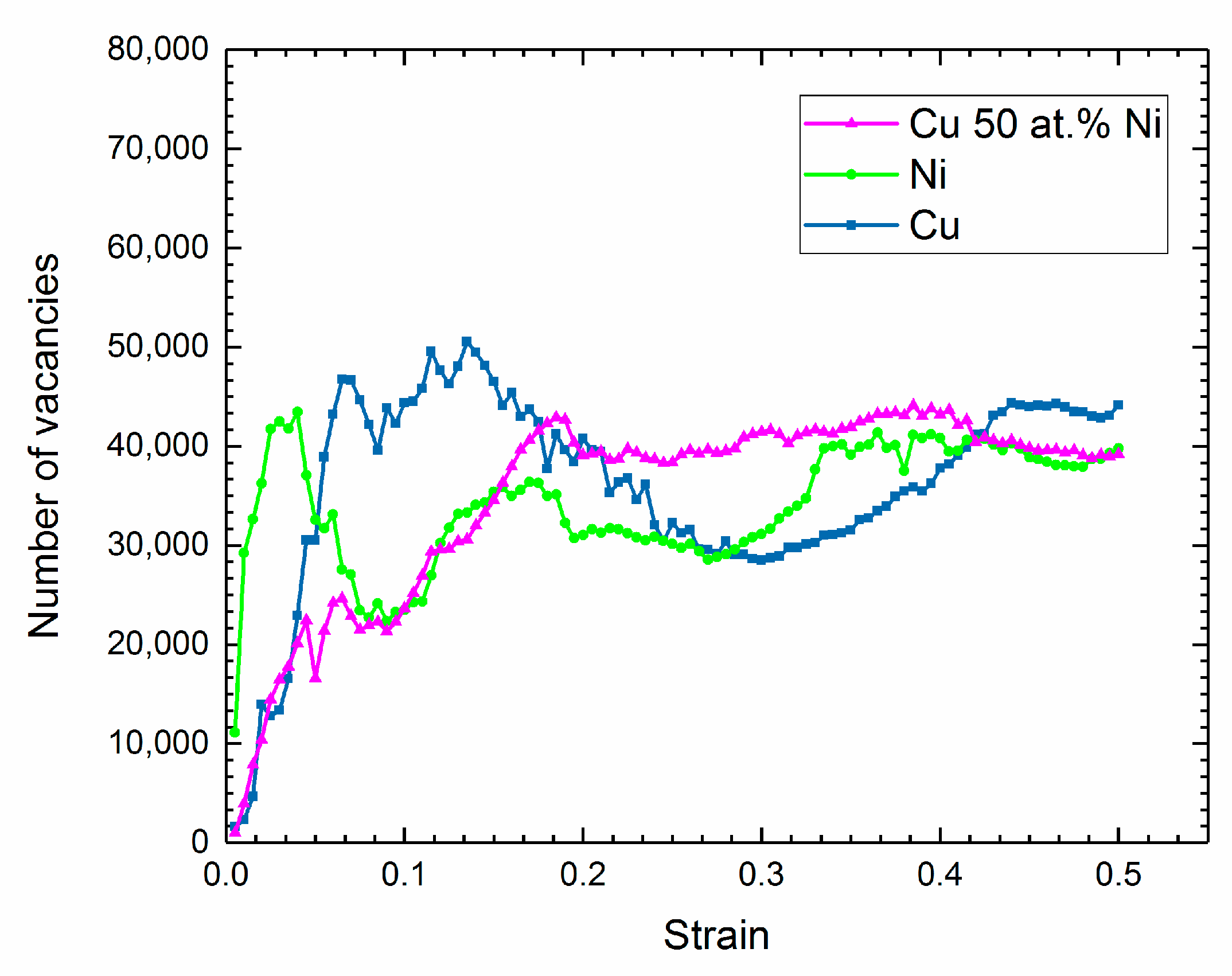
The number of vacancies formed in Cu, Ni, and equimolar Cu-Ni alloy polycrystals during the deformation is shown in Figure 10. In the copper at low strain, the number of vacancies formed in polycrystals increases, and reduces between 0.15–0.3 strain followed by another increase at higher strain. A similar trend was observed for nickel polycrystals with the difference that in the lower strain range (0.04–0.1), a reduction in the number of vacancies occurs. This is actually due to the fact in these polycrystals, the slip planes are more active around the grain boundaries (which was already observed by supersaturation of the dislocation around the grain boundaries) and therefore lead the grain boundaries to act as an ideal source for the sinking of vacancies. Interestingly, at higher strain, the number of vacancies formed in each polycrystal structure reaches an almost constant value. The increment in the number of vacancies in alloy will facilitate the dislocation climbing process, and as a result, the dislocation length increases, and gliding planes continue their movement in various directions which leads to the formation of an irregular network of dislocations.

3.6. Radial Distribution Function

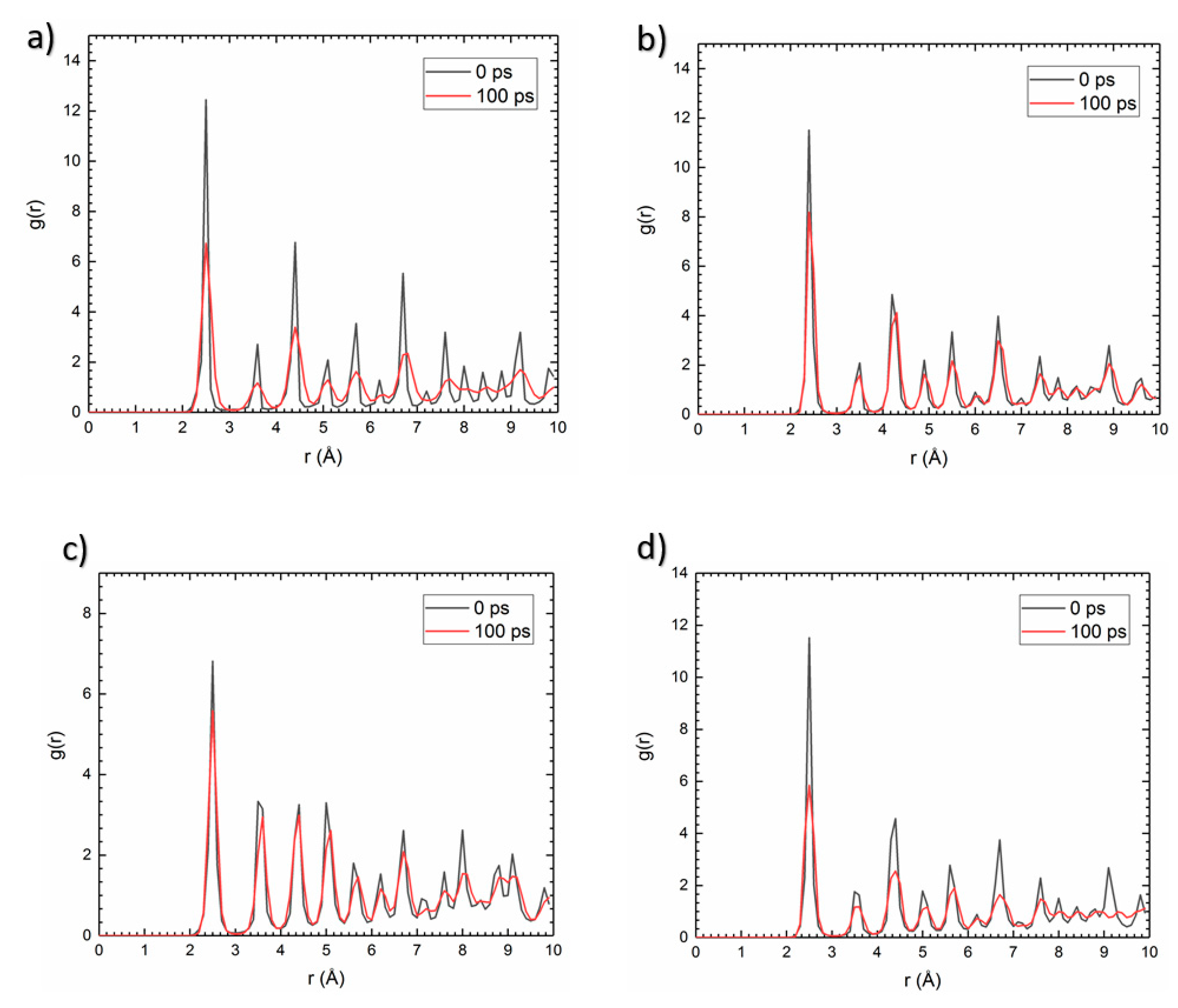
To clearly understand the ways in which the deformation affects segregation of atoms, the Radial Distribution Function (RDF) of the Cu-Cu and Ni-Ni atoms pair on polycrystals was evaluated in grain boundaries network before and after the deformation. Before the simulation process, the existence of sharp peaks in each polycrystal indicates the crystal structure. However, increased reduction in the intensity of peaks and broadening effect indicate atom segregation around the grain boundaries. Similar results have been obtained by Picard et al. in an investigation of the nickel polycrystal deformation mechanism by analyzing the radial distribution function in grain boundary network of nickel polycrystals [35]. By comparing the RDF results of the copper and nickel polycrystals, it can be seen that atom segregation is more pronounced in copper (Figure 11a,b). Interestingly, comparing the RDF results of the Cu-Cu and Ni-Ni atoms pair in equimolar Cu-Ni alloy shows that Ni-Ni solute interaction is more intense than that of Cu-Cu inside grain boundaries and Ni solute atoms have an amorphous arrangement (Figure 11c,d). On the other hand, due to the lesser reduction in the peak intensity for Cu-Cu and presence of some peaks at higher distance after the deformation, it can be said that nanoclusters of copper crystal are dispersed inside the amorphous phase of nickel clusters.

4. Conclusions

In summary, molecular dynamics simulation was carried out to understand the deformation mechanism in Cu, Ni, and equimolar Cu-Ni polycrystalline alloys by tracking the motion of dislocations around the grain boundaries. The results showed that in the Cu and Ni polycrystals, the dislocations accumulate near the grain boundaries. However, high density accumulation of dislocations inside the grains in equimolar Cu-Ni alloy was observed due to the formation of numerous shearing bands in different directions.
The dislocations begin to nucleate between the grains with almost the same orientation, the smallest grains, and the points that connect more than two grains. In the nickel and copper polycrystals, the hardening mechanism is based on the Taylor hardening theory, which declares that shear stress increases gradually with strain rate. However, the deformation behavior of the equimolar Cu-Ni alloy does not follow this theory.
Grain boundaries act as an ideal source for sinking of vacancies in copper and nickel polycrystals, but the number of vacancies formed in the structure raises constantly in the equimolar Cu-Ni alloy.
The radial distribution function results of the Cu-Cu and Ni-Ni atom pairs in equimolar Cu-Ni alloy show that nickel atoms segregate more intensely than copper, which shows that nanoclusters of copper crystal are dispersed inside the amorphous phase of nickel clusters after the deformation.

Author Contributions

S.Y.: Conceptualization, investigation, methodology, software, writing—original draft preparation. V.V.: Conceptualization, validation, supervision, writing—review and editing. All authors have read and agreed to the published version of the manuscript.

Funding

One of the authors (Sepehr Yazdani) wishes to thank Belgian Fonds De La Recherche Scientifique—FNRS for the financial support in the framework of the Aspirant scholarship.

Data Availability Statement

The data that support the findings of this study are available from the corresponding author upon reasonable request.

Conflicts of Interest

The authors declare no conflict of interest.

References

  1. Molaei, F.; Nojabaei, B. Atomistic Simulation of Temperature and Defects Effects on Mechanical Properties of Selected Single and Bicrystalline Geomaterials. J. Mol. Graph. Model. 2022, 117, 108320. [Google Scholar] [CrossRef]
  2. Zhang, F.; Li, G.; Zhu, D.; Zhou, J. Grain Size Effect on the Mechanical Behaviors in Nanocrystalline Cu-Ag Alloy with Grain Boundary Affect Zone Segregation. Mater. Lett. 2020, 278, 128406. [Google Scholar] [CrossRef]
  3. Qi, Y.; Xu, H.; He, T.; Feng, M. Effect of Crystallographic Orientation on Mechanical Properties of Single-Crystal CoCrFeMnNi High-Entropy Alloy. Mater. Sci. Eng. A 2021, 814, 141196. [Google Scholar] [CrossRef]
  4. Rao, S.I.; Antillon, E.; Woodward, C.; Akdim, B.; Parthasarathy, T.A.; Senkov, O.N. Solution Hardening in Body-Centered Cubic Quaternary Alloys Interpreted Using Suzuki’s Kink-Solute Interaction Model. Scr. Mater. 2019, 165, 103–106. [Google Scholar] [CrossRef]
  5. Antillon, E.; Woodward, C.; Rao, S.I.; Akdim, B.; Parthasarathy, T.A. Chemical Short Range Order Strengthening in a Model FCC High Entropy Alloy. Acta Mater. 2020, 190, 29–42. [Google Scholar] [CrossRef]
  6. Rupert, T.J. Solid Solution Strengthening and Softening Due to Collective Nanocrystalline Deformation Physics. arXiv 2014, arXiv:1407.5933. [Google Scholar] [CrossRef] [Green Version]
  7. Pun, S.C.; Wang, W.; Khalajhedayati, A.; Schuler, J.D.; Trelewicz, J.R.; Rupert, T.J. Nanocrystalline Al-Mg with Extreme Strength Due to Grain Boundary Doping. Mater. Sci. Eng. A 2017, 696, 400–406. [Google Scholar] [CrossRef] [Green Version]
  8. Rajgarhia, R.K.; Spearot, D.E.; Saxena, A. Plastic Deformation of Nanocrystalline Copper-Antimony Alloys. J. Mater. Res. 2010, 25, 411–421. [Google Scholar] [CrossRef]
  9. Rajgarhia, R.K.; Spearot, D.E.; Saxena, A. Heterogeneous Dislocation Nucleation in Single Crystal Copper–Antimony Solid-Solution Alloys. Model. Simul. Mater. Sci. Eng. 2009, 17, 55001. [Google Scholar] [CrossRef]
  10. Kamalakshi, G.; Pant, P.; Gururajan, M.P. Deformation Behaviour of Cu and Cu–Al in the Dislocation Starved Regime: A Molecular Dynamics Study. Comput. Mater. Sci. 2022, 203, 111087. [Google Scholar] [CrossRef]
  11. Mojumder, S.; Thakur, M.S.H.; Islam, M.; Mahboob, M.; Motalab, M. Numerical Investigation of Mechanical Properties of Aluminum-Copper Alloys at Nanoscale. J. Nanoparticle Res. 2021, 23, 1–20. [Google Scholar] [CrossRef]
  12. Szczerba, M.J.; Szczerba, M.S. Slip versus Twinning in Low and Very Low Stacking-Fault Energy Cu-Al Alloy Single Crystals. Acta Mater. 2017, 133, 109–119. [Google Scholar] [CrossRef]
  13. Martínez, C.; Briones, F.; Rojas, P.; Aguilar, C.; Guzman, D.; Ordoñez, S. Microstructural and Mechanical Characterization of Copper, Nickel, and Cu-Based Alloys Obtained by Mechanical Alloying and Hot Pressing. Mater. Lett. 2017, 209, 509–512. [Google Scholar] [CrossRef]
  14. Eder, S.J.; Grützmacher, P.G.; Rodríguez Ripoll, M.; Dini, D.; Gachot, C. Effect of Temperature on the Deformation Behavior of Copper Nickel Alloys under Sliding. Materials 2020, 14, 60. [Google Scholar] [CrossRef] [PubMed]
  15. Bryukhanov, I.A. Dynamics of Edge Dislocation in Cu–Ni Solid Solution Alloys at Atomic Scale. Int. J. Plast. 2020, 135, 102834. [Google Scholar] [CrossRef]
  16. Janani, R.D.; Salman, S.A.; Priyadharshini, K.P.; Karthik, V. Effect of Composition on the Stacking Fault Energy of Copper-Nickel Alloys Using Molecular Dynamics Simulations. Mater. Today Proc. 2021, 39, 1796–1800. [Google Scholar] [CrossRef]
  17. Vu, T.-N.; Pham, V.-T.; Fang, T.-H. Deformation Mechanisms and Mechanical Properties of Nanocrystalline CuxNi100− x Alloys during Indentation Using Molecular Dynamics. Mater. Today Commun. 2022, 33, 104282. [Google Scholar] [CrossRef]
  18. Doan, D.-Q.; Fang, T.-H.; Chen, T.-H. Influences of Grain Size and Temperature on Tribological Characteristics of CuAlNi Alloys under Nanoindentation and Nanoscratch. Int. J. Mech. Sci. 2020, 185, 105865. [Google Scholar] [CrossRef]
  19. Shinde, A.B.; Patil, S.; Patil, P.; Salunkhe, R.; Sande, R.; Pawar, S.; Patil, V. Dislocation and Deformation Analysis of Cu-Ni Thin Films during Nano-Indentation Using Molecular Dynamics Simulation Approach. Mater. Today Proc. 2022, 49, 1453–1461. [Google Scholar] [CrossRef]
  20. Pham, A.-V.; Fang, T.-H.; Tran, A.-S.; Chen, T.-H. Structural and Mechanical Characterization of Sputtered CuxNi100-x Thin Film Using Molecular Dynamics. J. Phys. Chem. Solids 2020, 147, 109663. [Google Scholar] [CrossRef]
  21. Hirel, P. Atomsk: A Tool for Manipulating and Converting Atomic Data Files. Comput. Phys. Commun. 2015, 197, 212–219. [Google Scholar] [CrossRef]
  22. Plimpton, S. Fast Parallel Algorithms for Short-Range Molecular Dynamics. J. Comput. Phys. 1995, 117, 1–19. [Google Scholar] [CrossRef] [Green Version]
  23. Srivastava, I.; Kotia, A.; Ghosh, S.K.; Ali, M.K.A. Recent Advances of Molecular Dynamics Simulations in Nanotribology. J. Mol. Liq. 2021, 335, 116154. [Google Scholar] [CrossRef]
  24. Fischer, F.; Schmitz, G.; Eich, S.M. A Systematic Study of Grain Boundary Segregation and Grain Boundary Formation Energy Using a New Copper–Nickel Embedded-Atom Potential. Acta Mater. 2019, 176, 220–231. [Google Scholar] [CrossRef]
  25. Stukowski, A.; Bulatov, V.V.; Arsenlis, A. Automated Identification and Indexing of Dislocations in Crystal Interfaces. Model. Simul. Mater. Sci. Eng. 2012, 20, 85007. [Google Scholar] [CrossRef]
  26. Stukowski, A. Visualization and Analysis of Atomistic Simulation Data with OVITO–the Open Visualization Tool. Model. Simul. Mater. Sci. Eng. 2009, 18, 15012. [Google Scholar] [CrossRef]
  27. Kato, M.; Fujii, T.; Onaka, S. Dislocation Bow-out Model for Yield Stress of Ultra-Fine Grained Materials. Mater. Trans. 2008, 49, 1278–1283. [Google Scholar] [CrossRef] [Green Version]
  28. Wang, J. Atomistic Simulations of Dislocation Pileup: Grain Boundaries Interaction. JOM 2015, 67, 1515–1525. [Google Scholar] [CrossRef]
  29. Han, X. Investigate the Constrained-Microplasticity of Nano-Polycrystal Silicon in Nanomachining Using Atomic Simulation Method. Appl. Phys. A 2022, 128, 1–14. [Google Scholar] [CrossRef]
  30. Zhao, P.; Guo, Y. Grain Size Effects on Indentation-Induced Defect Evolution and Plastic Deformation Mechanism of Ploycrystalline Materials. Comput. Mater. Sci. 2018, 155, 431–438. [Google Scholar] [CrossRef]
  31. Le, K.C.; Sembiring, P.; Tran, T.N. Continuum Dislocation Theory Accounting for Redundant Dislocations and Taylor Hardening. Int. J. Eng. Sci. 2016, 106, 155–167. [Google Scholar] [CrossRef]
  32. Kocks, U.F.; Mecking, H. Physics and Phenomenology of Strain Hardening: The FCC Case. Prog. Mater. Sci. 2003, 48, 171–273. [Google Scholar] [CrossRef]
  33. Tian, Y.Z.; Zhao, L.J.; Chen, S.; Shibata, A.; Zhang, Z.F.; Tsuji, N. Significant Contribution of Stacking Faults to the Strain Hardening Behavior of Cu-15% Al Alloy with Different Grain Sizes. Sci. Rep. 2015, 5, 1–9. [Google Scholar] [CrossRef] [PubMed] [Green Version]
  34. Sun, P.-L.; Zhao, Y.H.; Cooley, J.C.; Kassner, M.E.; Horita, Z.; Langdon, T.G.; Lavernia, E.J.; Zhu, Y.T. Effect of Stacking Fault Energy on Strength and Ductility of Nanostructured Alloys: An Evaluation with Minimum Solution Hardening. Mater. Sci. Eng. A 2009, 525, 83–86. [Google Scholar] [CrossRef]
  35. Picard, E.-A.; Sansoz, F. Ni Solute Segregation and Associated Plastic Deformation Mechanisms into Random FCC Ag, BCC Nb and HCP Zr Polycrystals. Acta Mater. 2022, 240, 118367. [Google Scholar] [CrossRef]
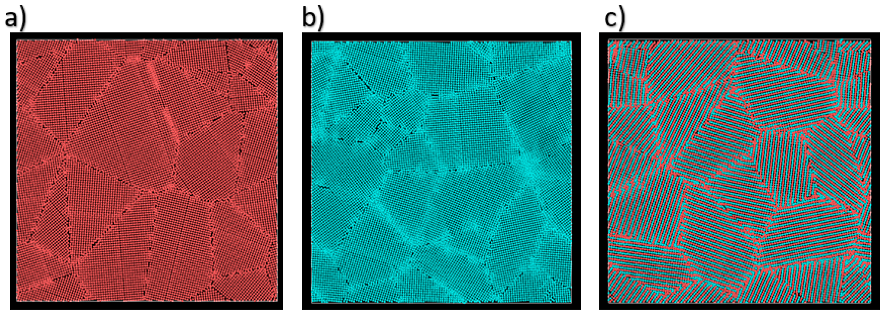
Figure 1. 2D image of the polycrystal structure of (a) Cu, (b) Ni, and (c) equimolar Cu-Ni alloy (the copper atoms are shown by the red color and the nickel atoms are shown b blue color).
Alloys 02 00005 g001
Figure 2. The polycrystalline structures built for the Cu, Ni, and equimolar Cu-Ni alloy.
Alloys 02 00005 g002
Figure 3. Molecular dynamics simulation snapshots from Dislocation extraction algorithm (DXA) for Cu at (a1) 0 ps, (a2) 20 ps, (a3) 60 ps, (a4) 100 ps, DXA for Ni at (b1) 0 ps, (b2) 20 ps, (b3) 60 ps, (b4) 100 ps, and DXA for equimolar Cu-Ni alloy at (c1) 0 ps, (c2) 20 ps, (c3) 60 ps, (c4) 100 ps.
Alloys 02 00005 g003
Figure 4. Dislocation extraction algorithm and atomic configuration of the equimolar Cu-Ni alloy at 5 ps.
Alloys 02 00005 g004
Figure 5. Shockley dislocation length as a function of strain.
Alloys 02 00005 g005
Figure 6. Stair-rod dislocation length as a function of strain.
Alloys 02 00005 g006
Figure 7. Inside view of the dislocation extraction algorithm for equimolar Cu-Ni alloy at 100 ps. The red circles show an area with high density of partial Shockley dislocation and the blue circle shows an area with low density of partial Shockley dislocation.
Alloys 02 00005 g007
Figure 8. Stress–strain curves of the Cu, Ni, and equimolar Cu-Ni alloy.
Alloys 02 00005 g008
Figure 9. The microstructure evolution simulation at 100 ps for (a) Cu, (b) Ni, and (c) equimolar Cu-Ni alloy. The green atoms show FCC structure, the red atoms show HCP structure, and the white atoms show amorphous structure.
Alloys 02 00005 g009
Figure 10. Number of formed vacancies during deformation as a function of strain.
Alloys 02 00005 g010
Figure 11. Radial distribution function in the precipitate (a) Cu-Cu atom pairs in copper, (b) Ni-Ni atom pairs in nickel, (c) Cu-Cu atom pairs in equimolar Cu-Ni alloy, (d) Ni-Ni atom pairs in equimolar Cu-Ni alloy.
Alloys 02 00005 g011
Disclaimer/Publisher’s Note: The statements, opinions and data contained in all publications are solely those of the individual author(s) and contributor(s) and not of MDPI and/or the editor(s). MDPI and/or the editor(s) disclaim responsibility for any injury to people or property resulting from any ideas, methods, instructions or products referred to in the content.