1. Introduction
Metal additive manufacturing (AM) has proven itself capable of producing complex parts for a wide range of applications [
1]. AM allows for the fabrication of parts with unique microstructures and significant geometric complexity compared to conventional metal forming techniques. Most metal AM systems use a high-energy laser to fuse metal powder particles together and form parts in a layer-by-layer manner according to a computer-aided design (CAD) program. Although based on similar principles, different AM systems make use of different powder delivery systems, energy sources, deposition strategies, etc. According to the process labeling established by ASTM International, powder bed fusion (PBF) systems such as selective laser melting (SLM) spread the powder on a bed, and then a laser is used to melt the particles in the desired locations before the next layer of powder is spread on the bed, whereas laser-directed energy deposition (L-DED) systems, such as laser engineered net shaping (LENS
®), use injection nozzles to spray powder into the focal point of the laser using an inert gas such as argon [
2].
Laser-based metal AM has been employed to process a variety of starting materials such as stainless steel, Al alloys, Ti alloys, and Ni-based superalloys, the results of which have been summarized in a comprehensive review by Gu et al. [
3]. Al alloys are used in many industries, from automobiles to aerospace, due to their light weight and high specific strength. Although different researchers have introduced novel methods to deposit high-strength (7xxx series) Al alloys in AM [
4,
5], AlSi10Mg is the most commonly used Al alloy in AM. AlSi10Mg, conventionally used as a casting alloy, demonstrates good wettability and castability, preventing hot cracking during the AM process. The processing and properties of AlSi10Mg are well documented for both PBF [
3,
6] and L-DED [
7,
8], demonstrating that both metal AM techniques can be successfully applied for processing AlSi10Mg parts.
Early studies such as the study by Sreenivasan et al. recognized these AM techniques as components of a novel approach to potentially reduce waste production, compared to conventional subtractive manufacturing methods, by eliminating metal scrap or swarf and minimizing the required post-processing steps [
9]. However, various studies have shown that powder waste during AM can be significant, unless the waste powder itself is recycled [
10,
11]. Ma et al. showed that the material capture efficiency, defined as the ratio between the amount of powder that is used to form the final part and the total powder that goes into the system, can be used as a metric to determine the amount of waste produced in the AM process [
12]. Powder capture efficiency is generally reported to be between 3 and 25% [
13], indicating that 75–97% of the powder used during AM will go to waste. Although the material capture efficiency can be adjusted using different processing parameters, improving the capture efficiency can sometimes come at the expense of the quality of the final part. One method of mitigating the waste due to low capture efficiency is through powder recycling—taking the waste powder from one build cycle and reusing it for the fabrication of other parts.
Although a large portion of the powder used in AM does not fuse to the final part, some of the loose particles can be physically modified by the laser or the AM process itself. The loose particles have the potential to interact with the laser or other hot surfaces in the chamber and undergo morphological changes. Additionally, the injection and flow of the powder particles during L-DED processing can influence the surface of the particles; the surfaces of particles can be affected by the friction due to particle–particle collisions and the friction between the particles and the powder transportation vessel. Several studies have been dedicated to understanding the effect of powder reuse on the characteristics of the powders themselves and the properties of the final parts. Powder characteristics include, but are not limited to, the shape, particle size, particle size distribution, surface finish, oxidation, and contamination on the surface. Terrassa et al. investigated the impact of reusing 316L stainless steel powders for nine cycles in L-DED [
14]. Compared to parts made from virgin powders, parts made from recycled powders exhibited minimal changes in their mechanical properties. Slotwinski et al. found that the particle size distribution of stainless steel powder increased after being recycled in direct metal laser sintering [
15]. Several groups have explored the recycling of AlSi10Mg powder in PBF systems [
16,
17,
18,
19]. For instance, Tradowsky et al. investigated the influence of post-processing and powder recycling and concluded that using recycled powders results in parts with a greater number of pores [
20]. They attributed the formation of irregularly shaped pores in the final parts to the formation of an oxide layer on the surface of the recycled powders. Shalnova et al. used L-DED to investigate the effect of powder recycling and showed no significant changes in the microstructure or tensile properties of Ti-6Al-4V parts with regard to used particle content [
21]. Most of these studies demonstrate that while recycled powders exhibit some changes in particle size and morphology and yield final parts with some reduction in mechanical properties, the final parts are still acceptable for most applications. It is noted, also, that the particle size distributions of the recycled powders are inconsistent among different studies. The study by Cordova et al. reported that recycled powders had larger particle sizes than virgin powders [
16] while Del Re et al. observed the opposite trend [
18]. These contradictory studies indicate that there are different factors before and during the deposition process that can influence the particle size.
To the authors’ knowledge, few studies have investigated reusing AlSi10Mg powders in L-DED systems. L-DED systems use a fundamentally different powder delivery system compared to PBF, which is particularly sensitive to feedstock particle size due to the use of powder injection nozzles. Changes in particle characteristics, such as particle size and morphology, can lead to changes in flowability, resulting in inconsistent powder delivery to the melt pool, which in turn will significantly influence the properties of the final build due to the formation of porosity [
22]. Therefore, understanding how powder reuse influences the mechanical properties of the final builds will require observing the interplay between the evolution in powder characteristics and flowability. Additionally, in our previous study, we observed that the powder density will influence the flowability of powders in L-DED [
23]. It would be expected that powders of Al-alloys, with their low densities, low melting temperatures, and mechanical softness, will exhibit a distinct evolution in powder characteristics as a result of powder reuse in L-DED compared to the more commonly studied stainless steel powders. Further investigation is therefore required to understand the effect of reusing Al alloy powder, specifically AlSi10Mg, on the reused powder characteristics and flowability, as well as the properties of the final builds. To this end, AlSi10Mg powder was consecutively recycled for five deposition cycles in the present study to elucidate the influence of reusing AlSi10Mg powder in L-DED. The changes in the particle morphology, particle size distribution, and flowability through the five reuse and deposition cycles were investigated. Mechanical and microstructure analyses were performed on the parts deposited with the virgin and recycled powders to assess how the recycling process influences the quality of the deposited parts. Statistical analysis was performed to determine the degree of correlation between the particle characteristics, flowability, and mechanical property values.
2. Materials and Methods
AlSi10Mg powder with a size range of 45–150 µm was purchased from Valimet Inc (Valimet, Stockton, CA, USA). Mechanical sieving was used to confirm the size of the AlSi10Mg powder particles. The powder was used in a LENS
® 1000 (Optomec, Albuquerque, NM, USA) workstation system to deposit blocks with dimensions of 3.81 cm × 1.01 cm × 1.01 cm on Al 6061 substrates. Based on the findings from our previous study, the deposition parameters were selected to be 600 W laser power, 16.9 mm/min scan speed, and 2 RPM powder feed rate [
7]. Virgin powder (referred to as P0 in this study) was used to deposit blocks that are considered as part of the first cycle (cycle C1, B1 blocks). Powder recovered from the first cycle (P1) that was not attached to the final parts was collected and sieved. The sieved powder was used for the following cycle (C2) to deposit blocks (B2) and make P2 powder. The same routine was continued for three more cycles, making a total of five cycles. A schematic flow chart of the process is shown in
Figure 1. Due to the amount of powder required for L-DED processing, only one batch of powder was collected for each reuse cycle and the above-described recycling sequence was only performed once, as was consistent with the approach from other studies on powder recycling in AM [
14,
18,
19,
24].
Due to the nozzle dimensions and powder injection system, the recommended particle size range for L-DED is between 45 µm and 150 µm [
25,
26]. Particles greater or smaller than 45–150 µm will not flow well in L-DED [
23], and are thus commonly excluded during L-DED [
1]. In our study, #325 and #100 mesh sieves were used to remove the particles outside the recommended range. Particles between 45 and 150 µm were collected and used for the following cycle. The particles outside the 45–150 µm range were collected and weighed in order to acquire information on the evolution in particle size during L-DED. All the block samples were deposited in a two-week period and the oxygen level was kept at less than 20 ppm. We note that all of the reused powders in this study contained only powder collected during deposition and were not combined with any virgin powder.
Particle size and morphology of the sieved powders were characterized using an FEI Quanta 3D scanning electron microscope (SEM) (Thermo Fischer Scientific, Waltham, MA, USA). Both the distribution in particle area,
A, as well as the largest and smallest Feret diameters for each powder were measured from the SEM micrographs using the Olympus Stream Basic
® version 2.2 image analysis software. A threshold analysis was performed before image analysis in order to eliminate features <5 µm in size. For each reuse cycle, >600 particles were measured to provide a statistically relevant number of measurements. All SEM micrographs in this study were acquired using secondary electron mode with a pixel size of 400 nm × 400 nm or smaller, thus satisfying the Merkus criteria requiring that particles contain at least 100 pixels and the minimum measured dimension consists of at least 10 pixels [
27].
Particle size (D
10, D
50, and D
90) in this paper is defined as the equivalent diameter of a circular particle with the same area as the particle captured in the SEM micrographs. The equivalent circle diameter is calculated using the formula
. Despite the complexity of the particle shapes in this study, we have chosen to use an equivalent circle diameter due to its simplicity and because it is a well-established parameter for conveying particle size in a single size parameter [
27]. The aspect ratio (AR
10, AR
50, AR
90) is the ratio between the largest and smallest cross-sectional dimensions of the particles, where 1.0 corresponds to a sphere. In this study, AR was calculated with the standard Feret approach, using the ratio of the largest Feret diameter to the smallest Feret diameter [
28]. Two common metrics are used to describe the distribution width in this study, the particle size ratio (D
90/D
10) [
29] and the span [
23]. Span represents the width of the particle size distribution and is calculated using the equation
.
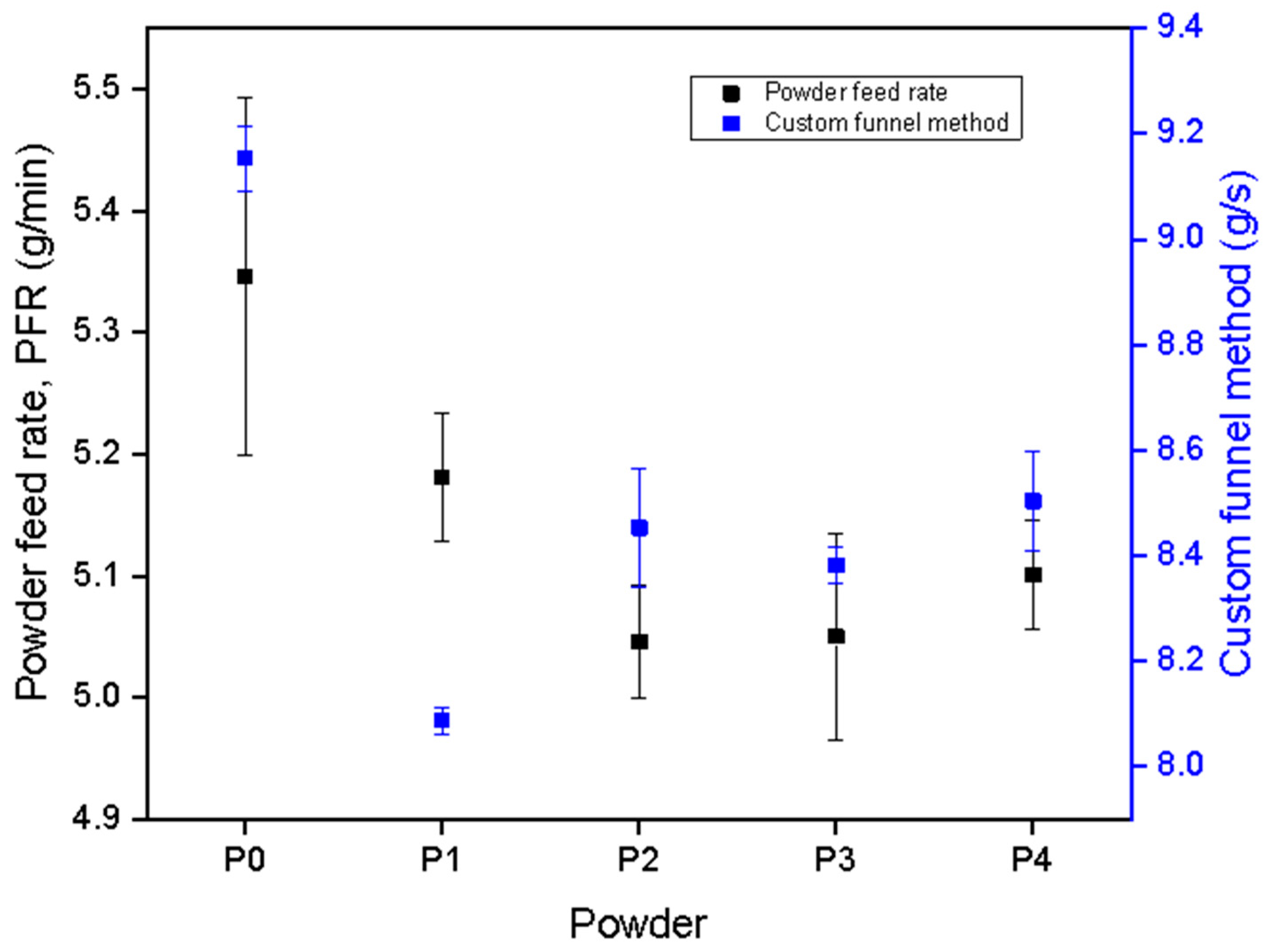
The flow rate of the particles was measured using two different methods. The first method, referred to as the “powder feed rate” (PFR) method, involves measuring the actual effective flow rate during a deposition experiment in units of g/min. In this study, PFR was calculated within the L-DED machine during each deposition by measuring the difference in the amount of powder in the hopper before and after deposition relative to the duration of the deposition. PFR provides the average powder flow rate for the whole deposition experiment. The second method involves measuring the powder flow rate using a custom-built funnel method. We refer to this method as the “custom-built funnel” method. A quantity of 50 g of powder was passed through a Pyrex funnel, and the required time for the powder to flow from the funnel was measured. A Photron SA-Z high-speed camera (Photron, Tokyo, Japan), operating at 500 frames per second (fps), was used to measure the required flow time more accurately. Further details on our custom-built funnel method can be found in a previous publication [
23]. Both flow rate measurements were performed three times after each reuse cycle. X-ray diffraction (XRD) was used to investigate the phase states of the powders from different cycles. XRD patterns were acquired using a SmartLab diffractometer (Rigaku, Tokyo, Japan) using Cu Kα radiation.
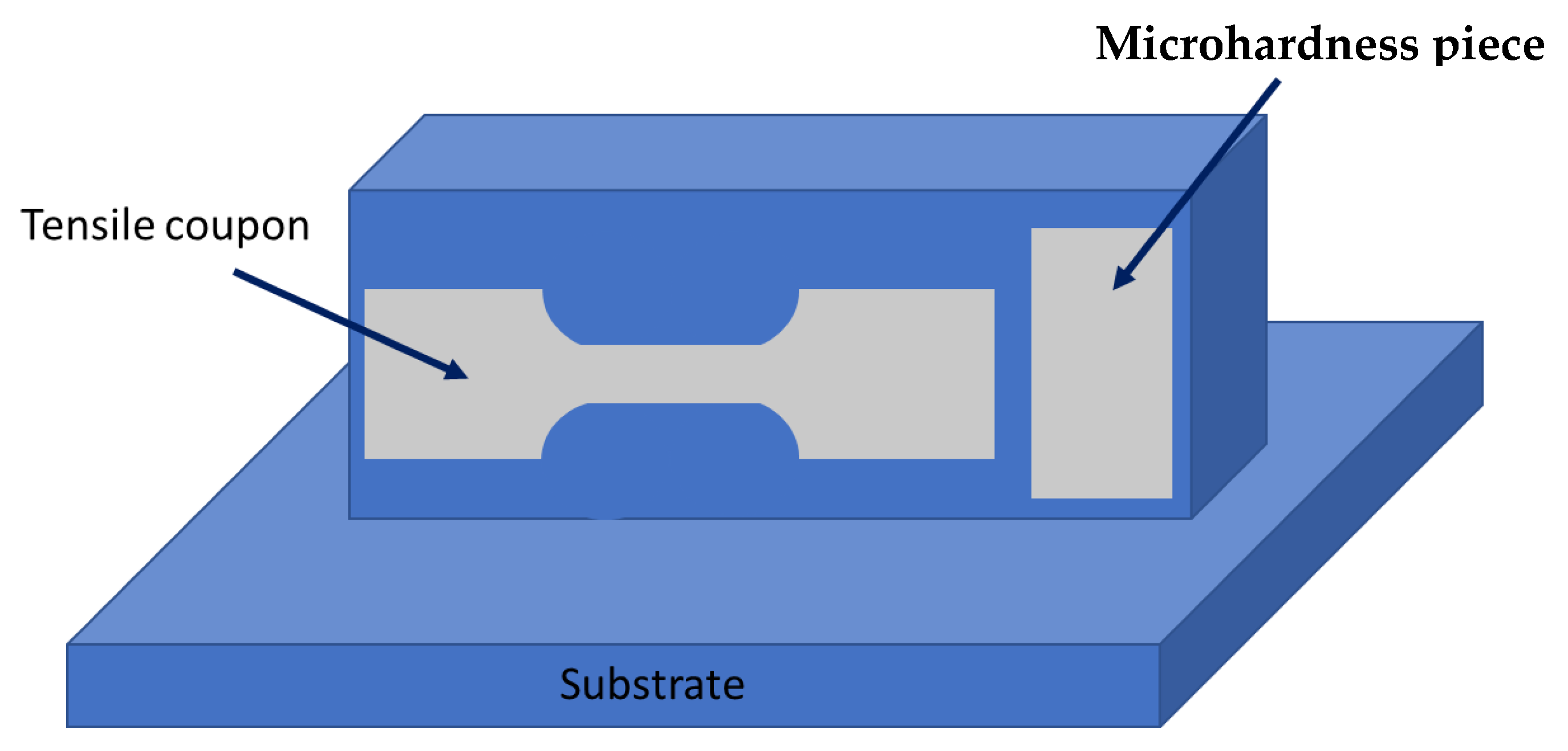
The blocks deposited in each cycle were used for density measurements, mechanical testing, and microstructure analysis. Dog bone coupons were cut using a Mitsubishi wire electrical discharge machine (EDM), model F020S (Mitsubishi Electric, Tokyo, Japan). The dog bone samples had a gauge length of 10 mm and a thickness of 1 mm, and were cut parallel to the build direction, as shown in the schematic in
Figure 2. Dog bones were polished and used for the tensile testing and density analysis. Sample densities in this study were measured in ethanol at room temperature using the Archimedes method [
30]. Tensile tests were performed on the dog bones using an Instron 8801 (Instron, Norwood, MA, USA) equipped with a 100 kN load cell and a video extensometer to resolve axial strain with a nominal strain rate of 0.001 s
−1. A separate piece of the build (referred to here as a microhardness piece) was cut from each block to be used for microhardness analysis, as shown in the schematic in
Figure 2. Vickers microhardness tests were conducted using a Struers Duramin 5 (Struers, Ballerup, Denmark) instrument with a force of 9.8 N and a 15-s hold. The microhardness values were obtained by averaging the results of 50 indents. All of the above-described measurements were performed on three block samples from each reuse cycle.
3. Results
The P0–P4 powders are primarily spherical, with some satellite features formed on their surfaces (
Figure 3). The powders exhibit the expected XRD patterns for the AlSi10Mg FCC structure, with no changes being observed in the XRD patterns with an increasing number of reuse cycles (
Figure 3f). No extraneous peaks were observed in any of the powder samples as well, confirming that reusing the AlSi10Mg powder does not affect the observed phase state and no meaningful contamination is being introduced during the recycling process.
The particle size distributions measured using SEM are displayed in
Figure 4a. The distributions generally shift to larger particle sizes with each reuse cycle, indicating that the particle sizes are increasing during recycling. The particle size (D
10, D
50, and D
90) increases with an increasing number of reuse cycles, as observed in
Figure 4b. The D
50 of the virgin powder (P0) was less than 80 µm. The D
50 increases with an increasing number of reuse cycles, with the D
50 becoming larger than 100 µm for cycles C3 and C4 (P3 and P4). The D
90/D
10 and the span values decrease with an increasing number of reuse cycles, as displayed in
Figure 4c. The particle size distribution narrows as the number of reuse cycles increases, with the span value decreasing from 0.51 for P0 powder to 0.38 for P4 powder. Additionally, semi-spherical and elongated morphologies can be observed in the particles from all the cycles. Both the AR
50 and AR
10 of the powders generally increase with an increasing number of reuse cycles (
Figure 4d). In contrast, the AR
90 remains mostly constant with an increasing number of reuse cycles, which we attribute to the retention of spherical particles that do not interact with the laser or melt pool during L-DED. Virgin powder (P0), with an AR
50 = 1.3, has the most spherical particles in this study, while powder from cycle P4 has the most non-spherical particles, having an AR
50 = 1.6.
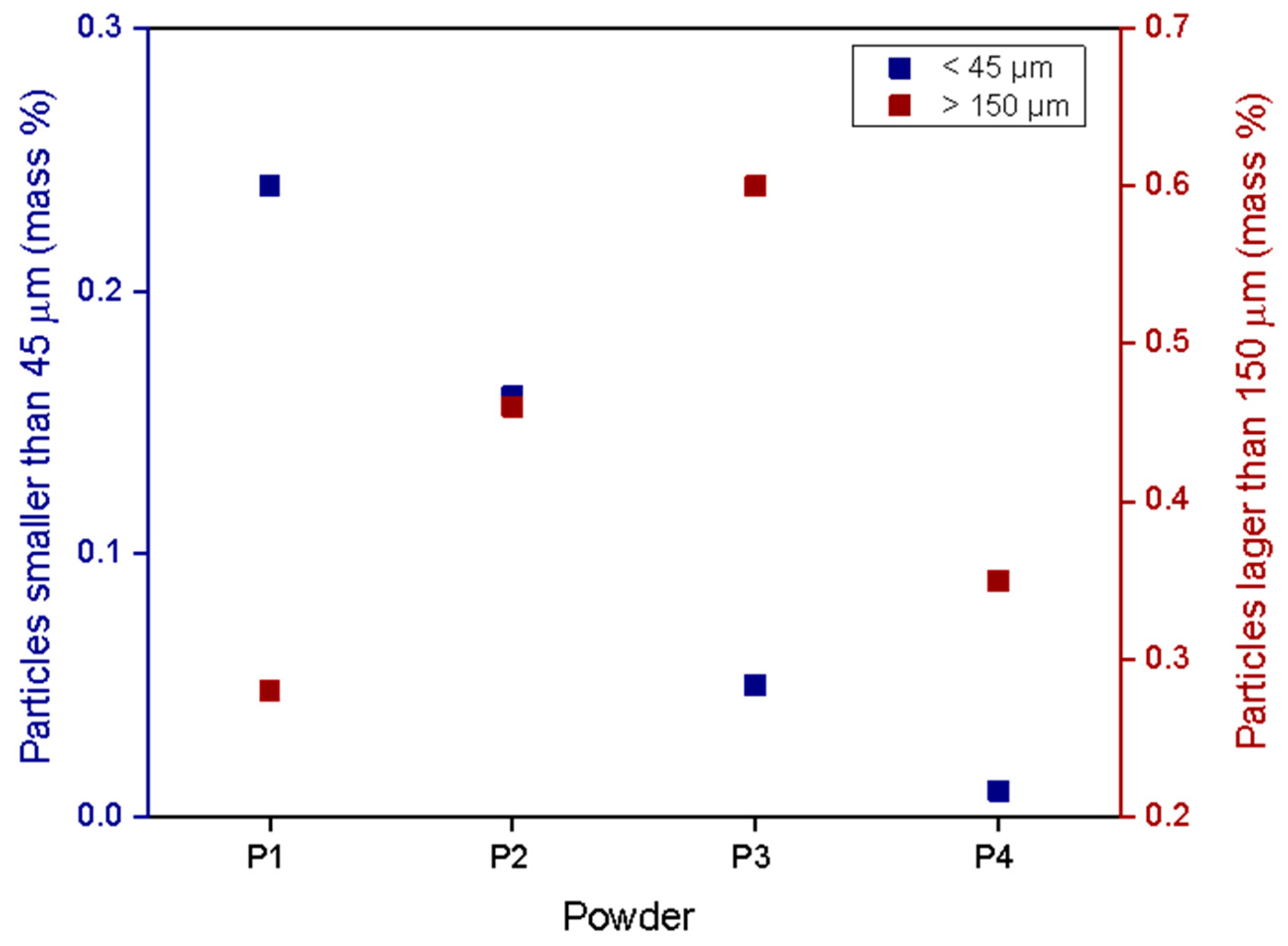
Sieving analysis was performed on all of the powders collected after each reuse cycle (
Figure 5), revealing that the powders collected after each cycle contained particles larger than 150 µm and smaller than 45 µm. On average, 0.11 mass % of the collected particles were smaller than 45 µm, and 0.34 mass % were larger than 150 µm for each cycle. The amount of the particles smaller than 45 µm decreased with an increasing number of reuse cycles. However, the number of particles larger than 150 µm did not follow an obvious trend with an increasing number of reuse cycles. The morphology of the particles larger than 150 µm collected in different cycles is displayed in
Figure 6. The micrographs of these particles suggest that the particles primarily consist of several particles that are fused to each other. However, individual semi-spherical particles that are larger than 150 µm are observed as well. It is important to note that the mass percent of powders that fall within the desired 45–150 µm range after reuse is ≥99%, indicating that almost all of the recycled powders are still suitable for L-DED.
The flow rate measurement results are displayed in
Figure 7, in which the data points correspond to the averages of the three measurements while the error bars denote the minimum and maximum values. Both the PFR and the custom-built funnel flow rate measurement techniques show similar flow rate behavior with an increasing number of reuse cycles. The P0 powder has a flow rate of 9.2 g/s, which is higher than that of the recycled powders (8.1–8.5 g/s). While this decline in flow rate is small, previous studies have shown that even small decreases in powder flowability can lead to large decreases in mechanical properties [
31], making it important to scrutinize even minor changes in powder flowability. However, no significant change in flow rate was observed between powders P1, P2, P3, and P4, indicating that an increased number of reuse cycles does not meaningfully impact powder flowability. The flow analysis of the powders in this study shows that our custom-built funnel method produces a similar trend in flowability behavior to what is observed in the PFR, confirming that our custom-built funnel measurement is an adequate proxy for observing relative changes in flowability during L-DED.
Both the virgin and recycled powders were used to deposit blocks using L-DED. The measured density values (
Figure 8a) show that the blocks are, on average, 99% dense compared to the theoretical density (2.68 g/cm
3 [
32]). Minimal variation in density is observed between the blocks fabricated with the P0–P4 powders. Further, the pore morphology in the block samples is similar among all the reuse cycles, with most of the pores having a spherical shape and size of approximately 20 µm in diameter. A representative image of a pore, similar in appearance to most of the pores observed in the block samples, is displayed in
Figure 8b.
The mechanical properties, tested in tension, of the blocks (B1–B5) deposited using the P0–P4 powders are displayed in
Figure 9. The highest ultimate tensile strength (UTS) and elongation-to-failure values in this study were 329 MPa and 9.7%, respectively, which are observed for the B1 build. There are reductions in UTS and elongation-to-failure to 303 MPa and 5% after the first reuse cycle (B2). However, UTS and elongation-to-failure values do not meaningfully change across blocks B2–B5. Conversely, the yield strength in the blocks exhibits minimal changes across the five cycles. The values of microhardness values in the blocks are also nearly constant with an increasing number of reuse cycles, except for the B3 samples, which exhibit the lowest microhardness value among all the blocks.
4. Discussion
The quality of the final parts in AM is influenced by a wide range of parameters that can be controlled directly and indirectly by the user. Among these parameters, powder characteristics have a significant indirect influence on the properties. Powder characteristics such as chemical composition, morphology, and particle size distribution can affect the AM process and, at the same time, the AM process can modify the characteristics of the waste powder. Particle size distribution and morphology influence the flowability and compactibility of the powders, which is discussed in more detail later. In this study, increasing the number of reuse cycles resulted in increases in the D
50 and AR
50 values and a decrease in the span. Santecchia et al. investigated the laser–metal powder interactions in PBF and showed that by-products such as condensate and spatter formed during the process [
33]. In L-DED systems, powders are ejected through nozzles aimed at the substrate, and the laser–powder interaction can be different compared to that observed in PBF. Haley et al. estimated the probability of detecting particles at a specific angle from the nozzle after they left the nozzle, moving toward the substrate [
34]. Their results suggest that not all the particles will be affected by the laser directly; however, they might still be affected by other particles. In PBF, the heat from the melt pool and laser travels through the powder particles, and some studies show that the particles are even melted before directly interacting with the laser [
35]. However, heat transfer is lower in a powder bed compared to a bulk sample because of the limited physical contact between the powder particles. Heat transfer between the particles is minimized in L-DED because it is a powder-fed method. While particles can collide and interact momentarily during L-DED, their interactions are brief and do not result in significant heat transfer.
In both L-DED and PBF, a high-pressure plume forms above the melt pool due to the evaporation of metal and the heat generated in the melt pool. Wolff et al. showed that the high-pressure plume in L-DED only allows specific particles to pass the plume barrier and enter the melt pool zone [
36]. The size, velocity, and trajectory of the particles play a role in determining whether a particle will enter the melt pool or not. Haley et al. used a high-speed camera and modeling to show that some of the particles that interfere with the laser absorb some energy and travel away from the melt pool while others absorb heat and enter the melt pool [
34,
37]. Yao et al. performed simulations of the L-DED process in order to investigate the relationship between microstructure and particle size distribution [
38]. Their findings suggest that a narrower particle size distribution will result in more uniform temperature gradients in the melt pool, which can lead to more equiaxed grains. Similarly, Iams et al. demonstrated that larger particles experience higher flow resistance during L-DED deposition, resulting in lower mass flow rates and noticeable inconsistency in the height and size of the single wall depositions [
39]. In addition, Shin et al. used a predictive model to show the temperature gradient that particles experience after leaving the nozzle [
40]. Their results indicate that not all the powder particles experience a temperature sufficient to induce melting. Wolff et al. used in situ X-ray imaging of the L-DED process and showed that some particles interfered with the laser before they were able to enter the vapor–plasma plume, and they were able to detect a shape change in those particles [
36]. During the deposition process, particles that are partially melted by the laser, or other hot surfaces, can experience morphological changes. Molten or partially molten particles can deform or fuse to other particles during a collision. Finer particles are particularly susceptible to such an event due to their smaller volumes making melting more likely. The morphologies of these deformed particles will depend on what the particles experience after melting. Little change in the particle morphology would be expected from particles that experience partial melting but then solidify before landing on the stage. Some of the partially melted particles collide and fuse with other particles. Particles that fuse together will yield a single particle with a larger size than the original particles, with repeating particle fusions resulting in a meaningful increase in the measured particle dimensions (i.e., D
50). Lastly, particles that impact the stage before solidification will have deformed or non-spherical shapes, with the extent of the change depending on the degree of melting and the speed with which the particles impact the substrate.
Non-thermal effects can also play a role in modifying individual particle characteristics. For example, lightweight fine particles (smaller than 45 µm) may fly further into the LENS
® chamber and be captured by the filtration system. However, additional fine particles can be produced as a result of splashes from the melt pool and from satellites breaking off from agglomerated particles during the powder feed and deposition process. Tang et al. have previously reported that particle–particle friction during AM causes the number of particles with satellites to be reduced in waste powders [
24]. Similar behavior was observed in this study, with reused particles having smoother surfaces compared to the virgin powders (
Figure 3). As mentioned earlier, particles smaller than 45 µm and larger than 150 µm could be found in each cycle. However, the number of fine particles (smaller than 45 µm) decreased with an increasing number of reuse cycles (
Figure 5), confirming that as the powder was being reused and subsequently sieved, the number of satellites decreased, fine particles were lost in the chamber, and the surfaces of the particles became smoother. Further, large particles (above 150 µm) were formed after every reuse cycle as a result of multiple particles fusing together, as shown in
Figure 6, which further reduced the concentration of fine particles in the powder. We therefore attribute our observed increase in D
50 with an increasing number of reuse cycles to the formation of fused particles and agglomerates as well as the loss of fine particles.
The above-described changes to particle size distribution will directly influence the flowability of the recycled powders (
Figure 7), leading to our observed variations in the mechanical behavior of the final builds (
Figure 9). Statistical analysis was performed to determine the degree of correlation between the particle size distribution, flowability, and mechanical property values. The Pearson correlation coefficient (R value) for the analyzed quantities was visualized using Corrplot [
41], as shown in
Figure 10. The colored circles correspond to the R values, with larger circles representing stronger correlations and smaller circles representing weaker correlations. The color bar displays the R values from negative (red) to positive (blue). Four key observations can be made from the data presented in
Figure 10: (1) the flowability parameters were negatively correlated to the particle size distribution and the particle aspect ratio, (2) UTS and elongation-to-failure had a strong positive correlation (defined here as R > 0.7) to the flowability values, (3) yield strength had a strong negative correlation with span, but was less strongly correlated to flowability than UTS and elongation-to-failure, and (4) Vickers hardness was not strongly correlated with flowability or particle characteristics.
Previous studies have clearly demonstrated a relationship between the powder physical characteristics, the powder flowability, and the properties of the final parts [
42,
43]. For example, Kiani et al. demonstrated that the morphology of the particles (i.e., AR
50) influences the initiation of powder flow from a static or compressed condition, while D
50 influences how well powders maintain their flow after flow has already begun [
23]. An inconsistent flow in L-DED systems such as LENS
® can result in brief shortages in available powder at any moment during deposition, which can lead to parts with low density (high porosity) and poor properties. For example, Freeman et al. showed that variations in the powder flow rate during L-DED will lead to inconsistencies in the melt track dimensions, leading to variations in the quality of deposited parts [
22].
It is important to note that prior to being further characterized, the fine and large particles were removed through sieving, leaving powder in the particle size range of 45–150 µm, as this is the particle size range that is most suitable for L-DED, due to the nozzle design and powder injection system [
25,
26]. The flow rate analysis in this study showed that the greatest change in powder flow rate occurred between the P0 powder and the P1 powder, which was related to the changes in the morphology and particle size distribution as a result of the L-DED process (
Figure 4). Further, our correlation analysis indicates that the flow rate is negatively correlated with particle size and aspect ratio (
Figure 10). Our previous study showed that as D
50 increases, flowability through nozzles and funnels decreases due to the larger particles being confined by a narrow exit diameter [
23]. Similarly, increasing span also decreases the flow rate due to an increase in the number of fine particles, which restrict flow by fitting in between larger particles. Conversely, AR
50 was shown to not strongly influence the flow rate of powders that had already begun to flow. The flow rate of the powder reached a plateau after two reuse cycles (P2 powder), which we attribute to the changes in the span and D
50 between the P1 and P4 cycles. In these samples, increasing the number of reuse cycles caused the span to decrease and the D
50 to increase, which had contradictory influences on the flow, thus preventing significant overall changes to the flow of the powder particles. The results from this study corroborate previous studies by showing that the flow rate of particles is reduced with an increasing number of reuse cycles. However, in this study, the flow rate reached a plateau after reusing the powders twice. Besides the changes in the morphology, size, and span of the particles, no phase change or measurable contamination was identified from the powder XRD patterns.
Various studies in the literature have investigated the relationship between powder recycling, powder flowability, and final part properties [
14,
18,
42,
44]. Seyda et al., for instance, demonstrated the relationship between the flowability of the particles and the properties of parts processed in AM [
42]. However, the previous literature is contradictory, with the changes appearing to be very material- and method-dependent. For example, studies by Sartin et al. and Terrassa et al. show that despite changes in morphology after powder reuse, the mechanical properties and density of the final builds do not vary significantly with an increasing number of reuse cycles [
14,
44]. Tang et al. showed an increase in the flow rate and mechanical properties of Ti6Al4V in selective electron beam melting [
24]. Similar behavior was reported by Seyda et al. [
45]. However, others such as Del Re et al. showed nearly constant mechanical properties with an increasing number of reuse cycles in AlSi10Mg made with PBF [
18].
In the current study, tensile and hardness measurements were used to examine the mechanical properties of the bulk-deposited samples. The observed UTS, elongation-to-failure, yield strength, and hardness values each exhibited a unique dependance on the number of reuse cycles. To summarize, the yield strength and microhardness vary within narrow ranges, 170–195 (MPa) for the yield strength and 90–105 Hv for the Vickers hardness. The UTS and elongation-to-failure values decrease after the first reuse cycle and then remain relatively constant with additional reuse cycles. From our statistical analysis (
Figure 10), we observe that UTS and elongation-to-failure have strong positive correlations with flow rate whereas yield strength and hardness are not as strongly correlated with flow rate. It has been shown in previous AM studies that the UTS and elongation-to-failure values are more sensitive to the presence of the pores in the samples whereas the microhardness and yield strength are more related to the grain size [
46,
47], suggesting that the changes we observe in the UTS and elongation-to-failure are the result of the porosity inside the samples. This porosity can be attributed to the declining flow rate with an increasing powder reuse, as discussed below. The consistency in the yield strength and microhardness values observed in the current study was expected, as the grain size is dependent on deposition parameters and thermal history, which were not varied in this study.
Consistent powder flowability during L-DED is critical to achieve successful builds as inconsistencies in the flow rate can affect the available material in the melt pool. Studies have shown that the excess particles resulting from a sudden increase in the flow rate can block the melt pool from accepting more particles and block the laser from providing energy into the melt pool [
37]. Conversely, a shortage of particles due to a low flow rate can increase the chance of pore formation or result in undesired build dimensions. A deficiency in the available material can result in large and irregular lack-of-fusion pores that are detrimental to the UTS and elongation-to-failure properties. However, as Haley et al. showed, powder fed systems benefit from a passive stability mechanism that can overcome the changes in the flow rate and height buildup in different layers during deposition [
34]. Nevertheless, changes in the mechanical properties are expected if the flow rate is inconsistent during deposition. Our UTS and elongation-to-failure values decreased after the first reuse cycle and then remain relatively constant with additional reuse cycles. Although decreasing with an increasing number of reuse cycles, the UTS values observed in this study fell within a narrow range of 286–328 MPa. Conversely, the elongation-to-failure declined significantly after the first reuse cycle, decreasing from 9.7% in block B1 to 5.0% in block B2. Despite the decrease with an increasing number of reuse cycles, our elongation-to-failure values were still similar to those observed in other studies on the AM of AlSi10Mg [
48]. The trend in UTS and elongation-to-failure with number of reuse cycles (
Figure 9a) followed a similar trend as observed between powder flow rate and number of reuse cycles (
Figure 7), which was confirmed by the strong correlation of UTS and elongation-to-failure with powder flow rate (
Figure 10). We therefore attribute the decline in UTS and elongation-to-failure with the number of reuse cycles to the decrease in the powder flow rate and resulting increase in lack-of-fusion porosity. It should be noted that the bulk density of all of our deposited blocks was >98%, regardless of the number of reuse cycles. We hypothesize that our increase in lack-of-fusion porosity was small enough to be below the detection limit of the Archimedes method. Our previous study on L-DED of AlSi10Mg found that the UTS and elongation-to-failure decreased from 355 MPa and 6%, respectively, at the top of the build, to 335 MPa and 4% at the bottom [
7]. We attributed this gradient in mechanical properties to a gradient in lack-of-fusion porosity, which was observable using microscopy but undetectable using Archimedes density measurements. The decline in mechanical properties due to lack-of-fusion porosity in our previous study was numerically similar to the decline in properties in the present study. Given the decrease in powder flowability after the single reuse cycle, the decreases in UTS and elongation-to-failure in samples B2–B5 are attributed to an increase in the number of lack-of-fusion pores.


