
Powder Production via Atomisation and Subsequent Laser Powder Bed Fusion Processing of Fe+316L Steel Hybrid Alloy

 ,
,  , , ,
, , ,
Abstract
1. Introduction
2. Materials and Methods
2.1. Powder Production and Subsequent Processing
2.2. Particle Size Analysis
2.3. Laser Powder Bed Fusion Processing
2.4. Heat Treatment
2.5. Optical Emission Spectrometer Measurements
2.6. Microstructure and Porosity Analysis
2.7. Hardness and Tensile Properties
3. Results
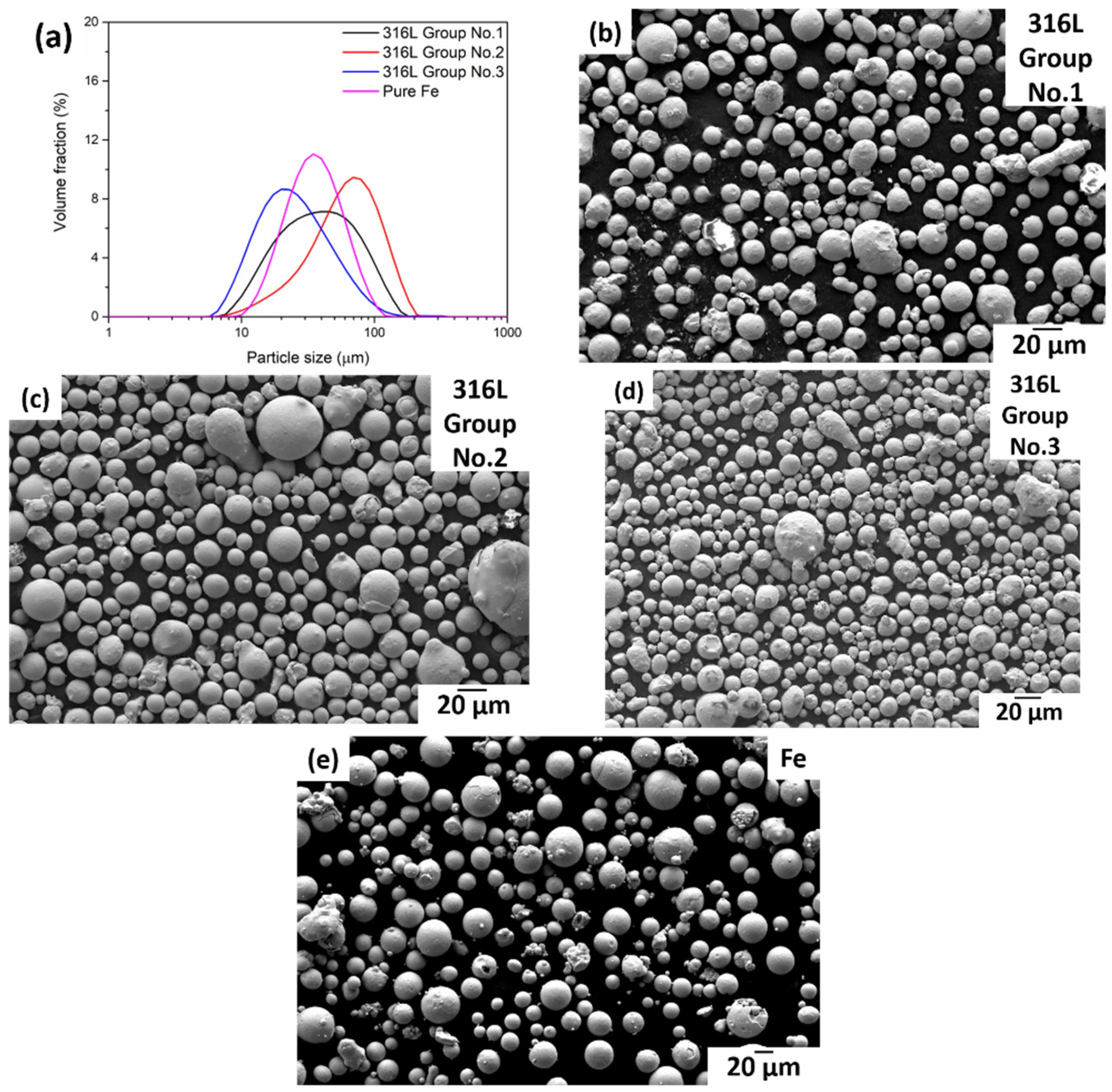
3.1. Powder Morphology and Characteristics
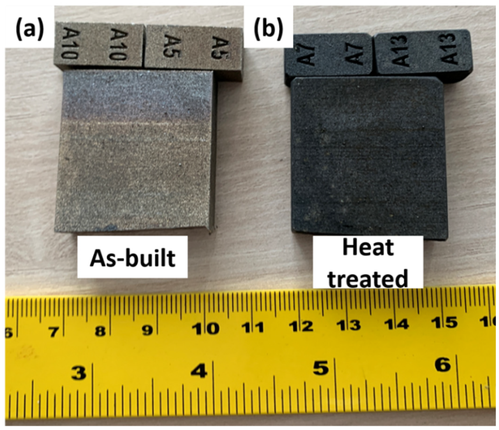
3.2. As-Built and Heat-Treated Samples
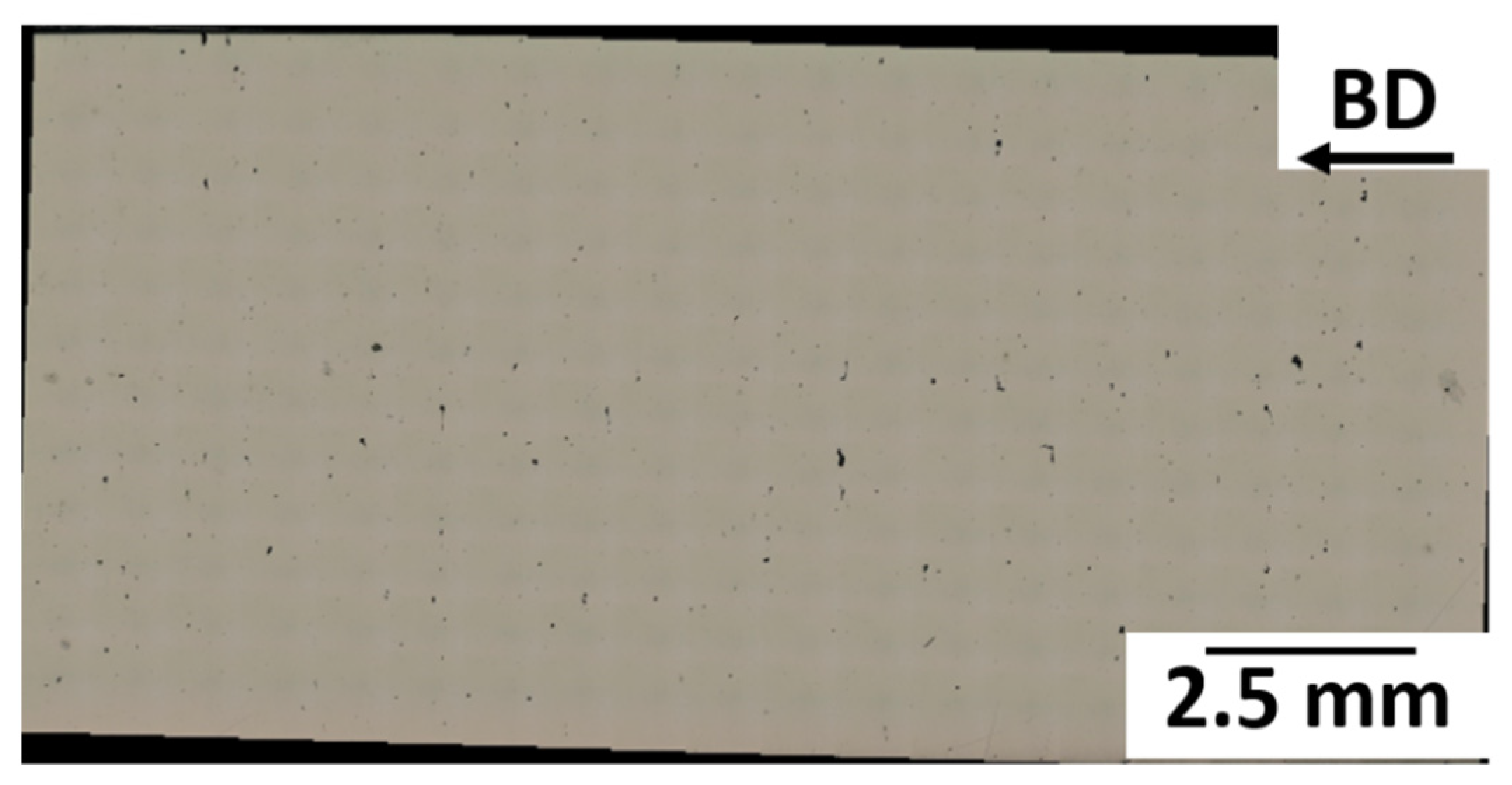
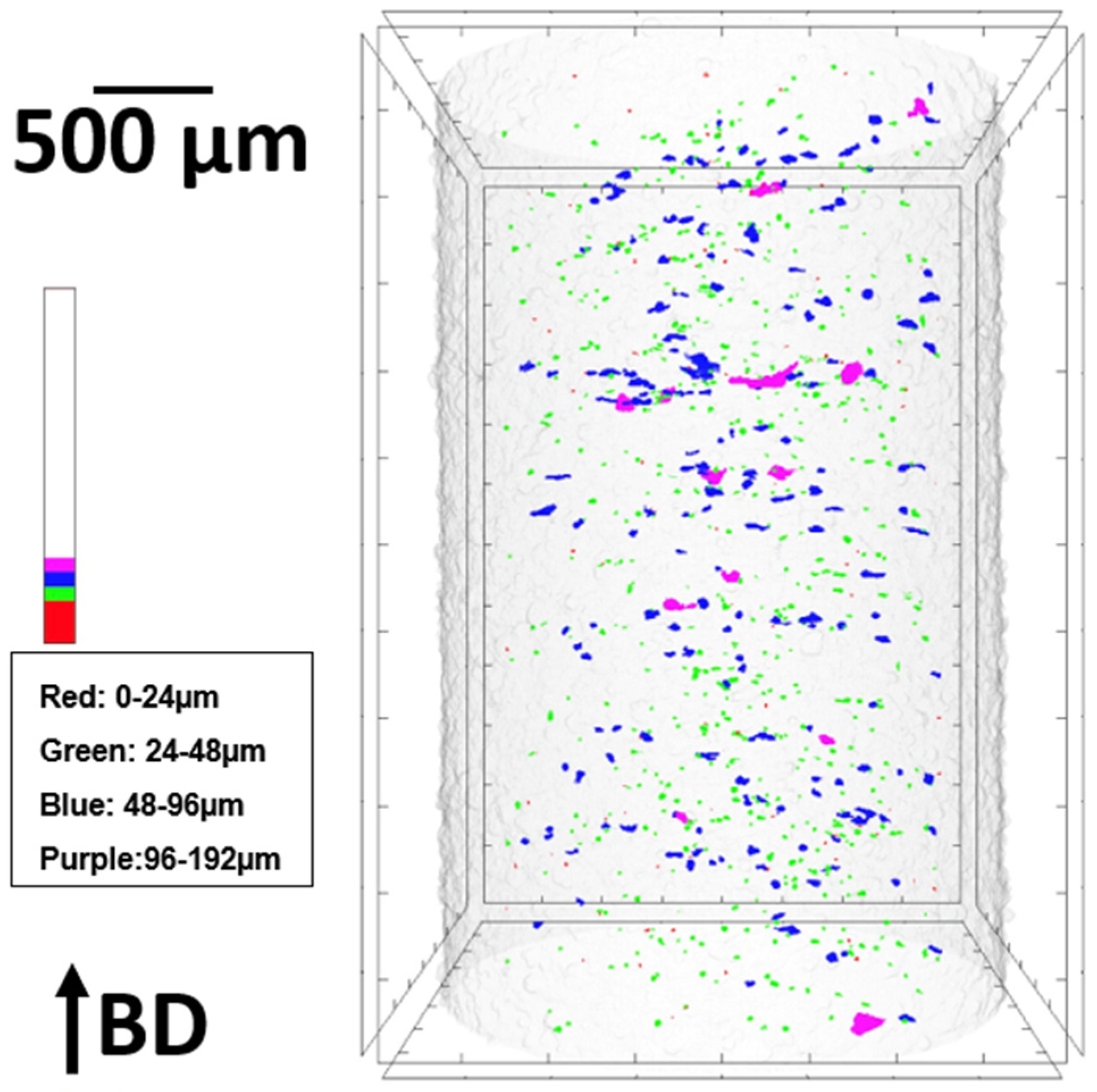
3.3. Porosity and Relative Density
3.4. Microstructural Analysis
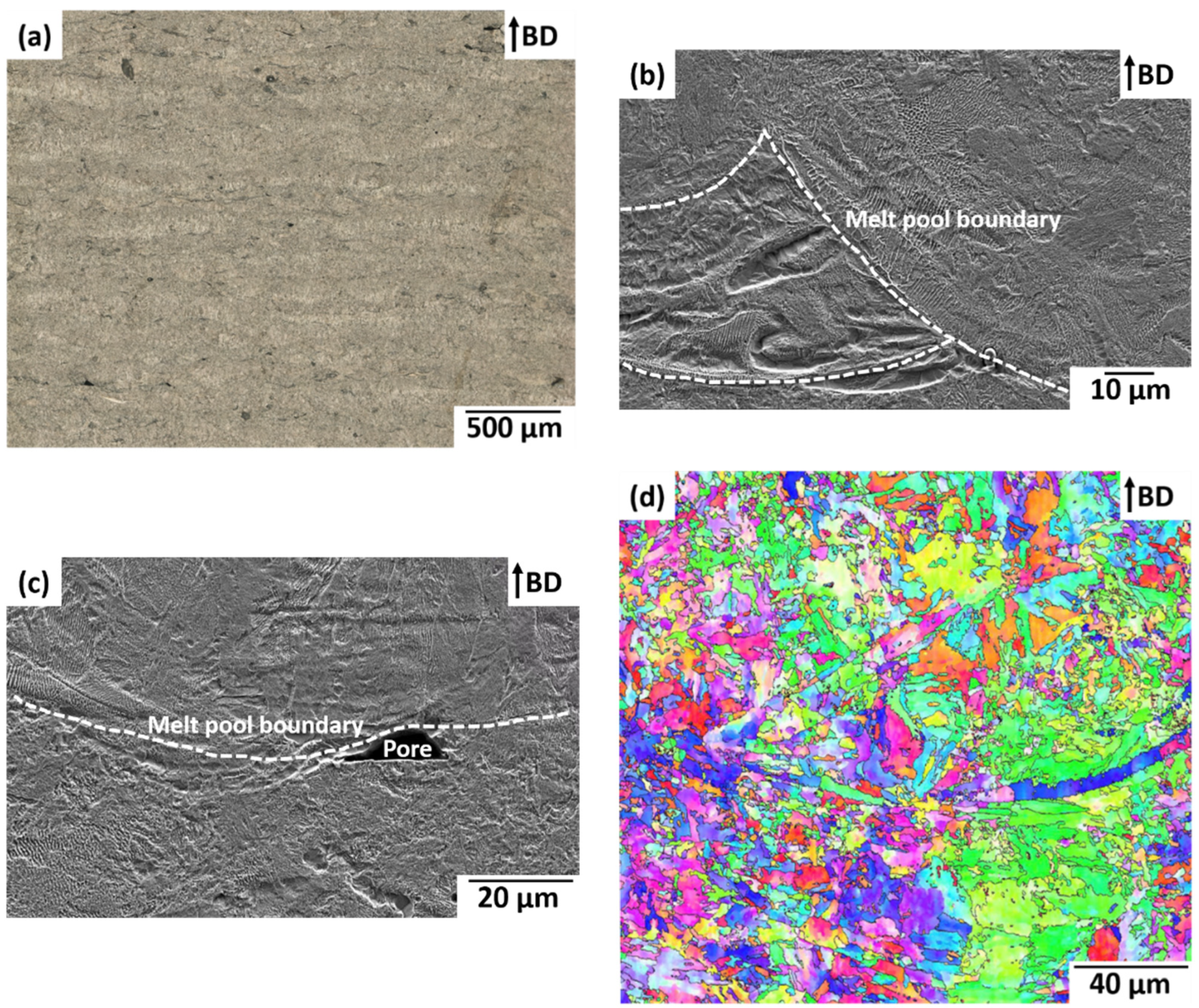
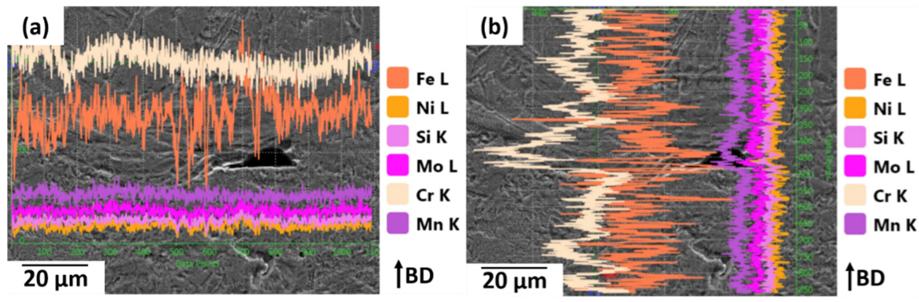
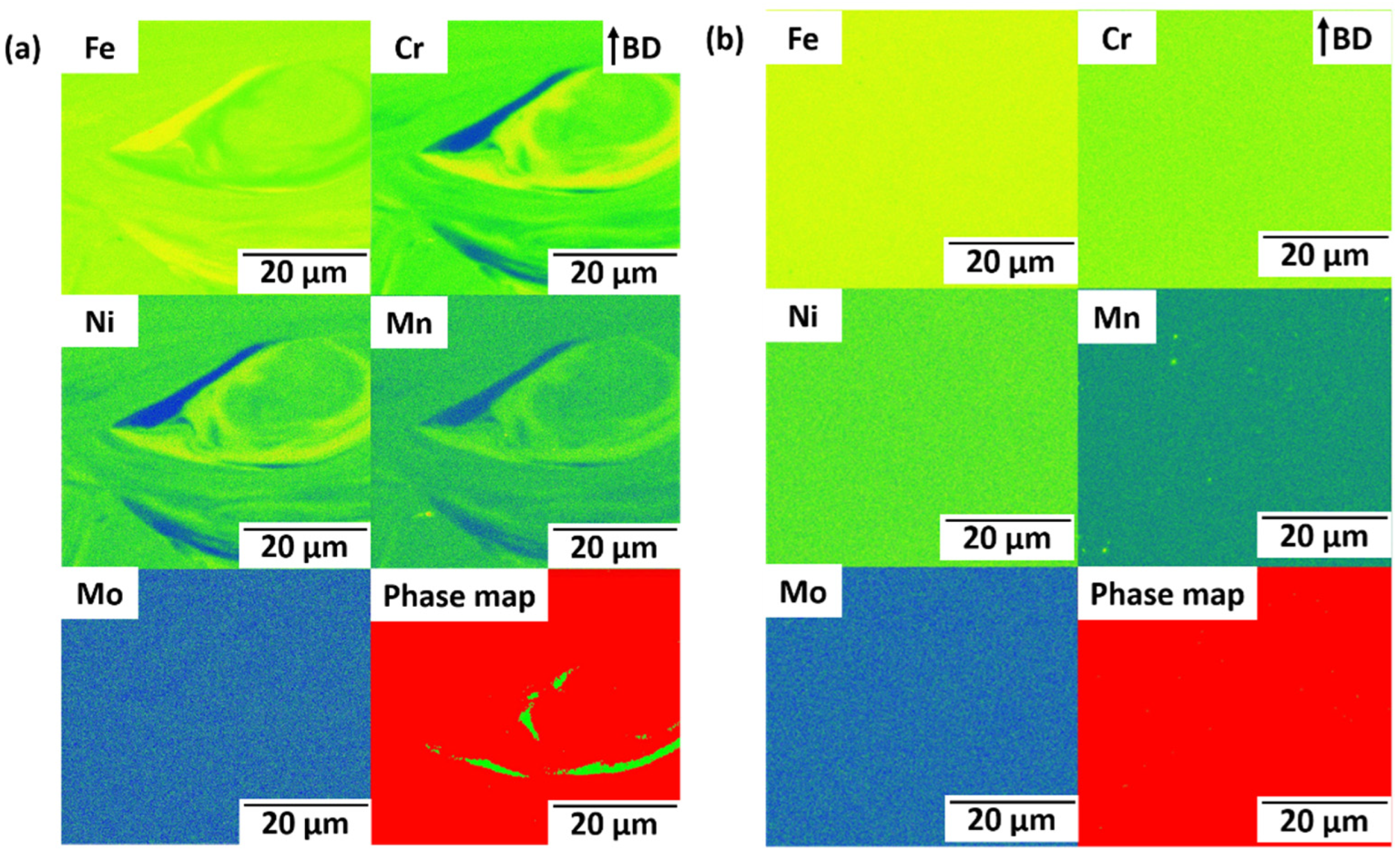
3.4.1. As-Built Sample
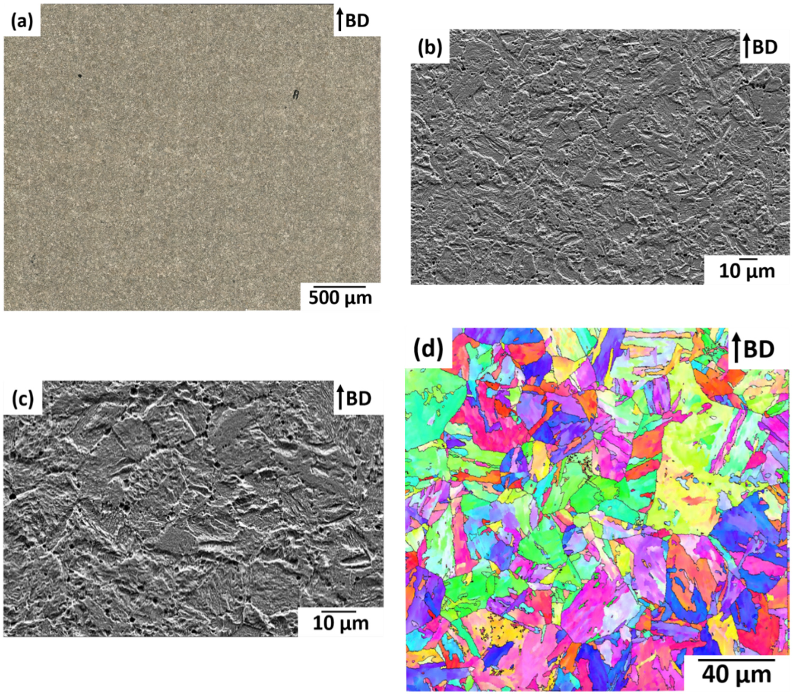
3.4.2. Heat-Treated Sample
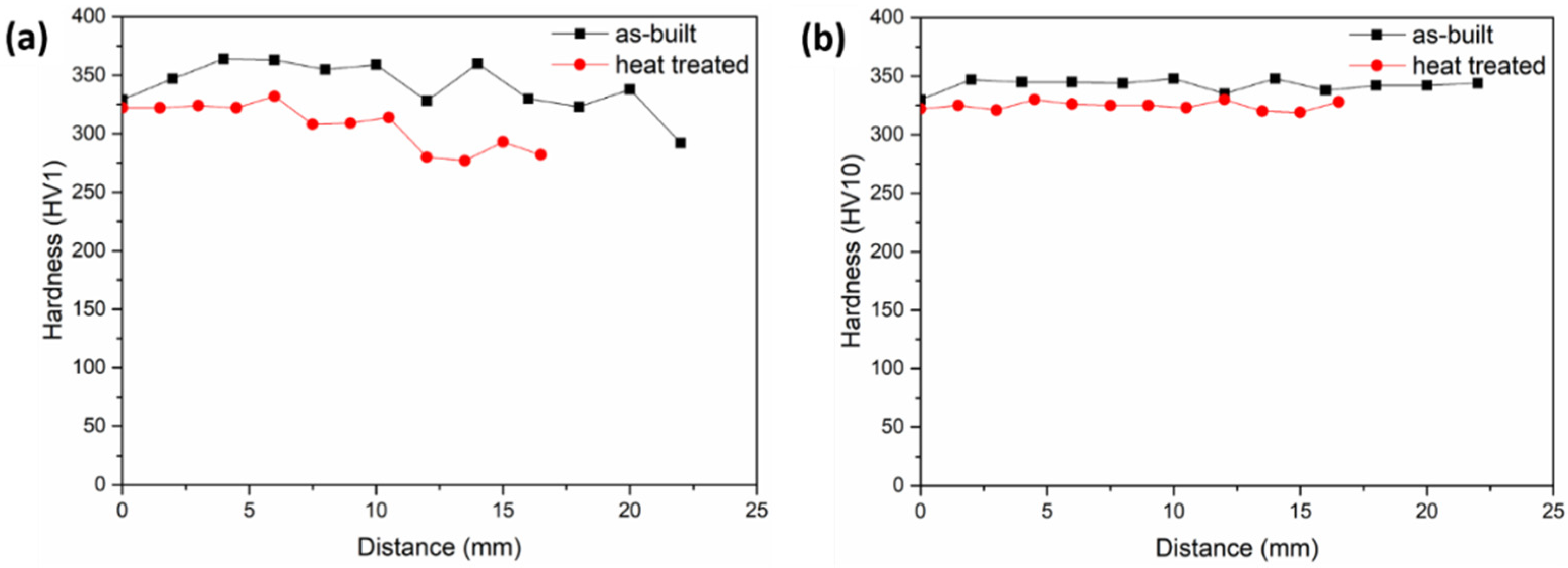
3.5. Hardness Analysis
3.6. Chemical Composition Analysis
4. Discussion
5. Conclusions
Author Contributions
Funding
Institutional Review Board Statement
Informed Consent Statement
Data Availability Statement
Acknowledgments
Conflicts of Interest
References
- Huang, G.; Wei, K.; Deng, J.; Liu, M.; Zeng, X. High-power laser powder bed fusion of 316L stainless steel: Defects, microstructure, and mechanical properties. J. Manuf. Process. 2022, 83, 235–245. [Google Scholar] [CrossRef]
- Ahmed, N.; Barsoum, I.; Haidemenopoulos, G.; Al-Rub, R.K.A. Process parameter selection and optimization of laser powder bed fusion for 316L stainless steel: A review. J. Manuf. Process. 2022, 75, 415–434. [Google Scholar] [CrossRef]
- Leicht, A.; Fischer, M.; Klement, U.; Nyborg, L.; Hryha, E. Increasing the Productivity of Laser Powder Bed Fusion for Stainless Steel 316L through Increased Layer Thickness. J. Mater. Eng. Perform. 2021, 30, 575–584. [Google Scholar] [CrossRef]
- Babu, S.S.; Love, L.; Dehoff, R.; Peter, W.; Watkins, T.R.; Pannala, S. Additive manufacturing of materials: Opportunities and challenges. MRS Bull. 2015, 40, 1154–1161. [Google Scholar] [CrossRef]
- Murr, L.E.; Gaytan, S.M.; Medina, F.; Lopez, H.; Martinez, E.; MacHado, B.I.; Hernandez, D.H.; Martinez, L.; Lopez, M.I.; Wicker, R.B.; et al. Next-generation biomedical implants using additive manufacturing of complex, cellular and functional mesh arrays. Philos. Trans. R. Soc. A Math. Phys. Eng. Sci. 2010, 368, 1999–2032. [Google Scholar] [CrossRef] [PubMed]
- Dehestani, M.; Trumble, K.; Wang, H.; Wang, H.; Stanciu, L.A. Effects of microstructure and heat treatment on mechanical properties and corrosion behavior of powder metallurgy derived Fe–30Mn alloy. Mater. Sci. Eng. A 2017, 703, 214–226. [Google Scholar] [CrossRef]
- Dargusch, M.S.; Dehghan-Manshadi, A.; Shahbazi, M.; Venezuela, J.; Tran, X.; Song, J.; Liu, N.; Xu, C.; Ye, Q.; Wen, C. Exploring the Role of Manganese on the Microstructure, Mechanical Properties, Biodegradability, and Biocompatibility of Porous Iron-Based Scaffolds. ACS Biomater. Sci. Eng. 2019, 5, 1686–1702. [Google Scholar] [CrossRef] [PubMed]
- Krüger, J.T.; Hoyer, K.-P.; Huang, J.; Filor, V.; Hernan Mateus-Vargas, R.; Oltmanns, H.; Meißner, J.; Grundmeier, G.; Schaper, M. FeMn with Phases of a Degradable Ag Alloy for Residue-Free and Adapted Bioresorbability. J. Funct. Biomater. 2022, 13, 185. [Google Scholar] [CrossRef] [PubMed]
- Tonna, C.; Wang, C.; Mei, D.; Lamaka, S.V.; Zheludkevich, M.L.; Buhagiar, J. Biodegradation behaviour of Fe-based alloys in Hanks’ Balanced Salt Solutions: Part I. material characterisation and corrosion testing. Bioact. Mater. 2022, 7, 426–440. [Google Scholar] [CrossRef] [PubMed]
- Perez, N. Electrochemistry and Corrosion Science. Electrochem. Corros. Sci. 2004, 189–246. [Google Scholar] [CrossRef]
- Liu, B.; Zheng, Y.F. Effects of alloying elements (Mn, Co, Al, W, Sn, B, C and S) on biodegradability and in vitro biocompatibility of pure iron. Acta Biomater. 2011, 7, 1407–1420. [Google Scholar] [CrossRef] [PubMed]
- Lee, M.K.; Lee, H.; Park, C.; Kang, I.G.; Kim, J.; Kim, H.E.; Jung, H.D.; Jang, T.S. Accelerated biodegradation of iron-based implants via tantalum-implanted surface nanostructures. Bioact. Mater. 2022, 9, 239–250. [Google Scholar] [CrossRef] [PubMed]
- Morsiya, C. A review on parameters affecting properties of biomaterial SS 316L. Aust. J. Mech. Eng. 2020, 20, 803–813. [Google Scholar] [CrossRef]
- Gas-Atomiser AUG 500–25000 | Blue Power Casting Systems GmbH. Available online: https://www.bluepower-casting.com/produkte/metallpulver-herstellung/gas-atomiser/ (accessed on 18 September 2022).
- Smirnov, M.A.; Kaplan, M.A.; Sevostyanov Udo, M.A. Receiving finely divided metal powder by inert gas atomization. IOP Conf. Ser. Mater. Sci. Eng. 2018, 347, 012033. [Google Scholar] [CrossRef]
- Henein, H.; Uhlenwinkel, V.; Fritsching, U.; Uhlenwinkel, V. Metal Sprays and Spray Deposition; Springer International Publishing: Cham, Switzerland, 2017; ISBN 9783319526898. [Google Scholar]
- Ciftci, N.; Ellendt, N.; Soares Barreto, E.; Mädler, L.; Uhlenwinkel, V. Increasing the amorphous yield of {(Fe0.6Co0.4)0.75B0.2Si0.05}96Nb4 powders by hot gas atomization. Adv. Powder Technol. 2018, 29, 380–385. [Google Scholar] [CrossRef]
- Froes, F.; Boyer, R. Additive Manufacturing for the Aerospace Industry, 1st ed.; Elsevier: Amsterdam, The Netherlands, 2019. [Google Scholar]
- Hengsbach, F.; Koppa, P.; Holzweissig, M.J.; Aydinöz, M.E.; Taube, A.; Hoyer, K.P.; Starykov, O.; Tonn, B.; Niendorf, T.; Tröster, T.; et al. Inline additively manufactured functionally graded multi-materials: Microstructural and mechanical characterization of 316L parts with H13 layers. Prog. Addit. Manuf. 2018, 3, 221–231. [Google Scholar] [CrossRef]
- Bobbio, L.D.; Otis, R.A.; Borgonia, J.P.; Dillon, R.P.; Shapiro, A.A.; Liu, Z.K.; Beese, A.M. Additive manufacturing of a functionally graded material from Ti-6Al-4V to Invar: Experimental characterization and thermodynamic calculations. Acta Mater. 2017, 127, 133–142. [Google Scholar] [CrossRef]
- El-Galy, I.M.; Saleh, B.I.; Ahmed, M.H. Functionally graded materials classifications and development trends from industrial point of view. SN Appl. Sci. 2019, 1, 1378. [Google Scholar] [CrossRef]
- Bleckmann, C.-E. Die Härterei: Einrichtung und Betrieb; Springer: Berlin/Heidelberg, Germany, 1968. [Google Scholar]
- Teng, X.; Zhang, G.; Liang, J.; Dong, Z.; Li, W.; Zhang, Q.; Yuan, P.; Gu, D.; Yuan, P.; Gu, D. Molten pool behaviour and its physical mechanism during selective laser melting of TiC/AlSi10Mg nanocomposites: Simulation and experiments. J. Phys. D Appl. Phys. 2015, 48, 035303. [Google Scholar] [CrossRef]
- Poprawe, R. Lasertechnik für die Fertigung; Springer Vieweg: Berlin/Heidelberg, Germany, 2005. [Google Scholar]
- Kruth, J.P.; Levy, G.; Klocke, F.; Childs, T.H.C. Consolidation phenomena in laser and powder-bed based layered manufacturing. CIRP Ann. 2007, 56, 730–759. [Google Scholar] [CrossRef]
- Dubberstein, T. Beiträge zu den Thermophysikalischen Eigenschaften Flüssiger Metallschmelzen. Ph.D. Thesis, Technischen Universität Bergakademie Freiberg, Freiberg, Germany, 2015. [Google Scholar]
- Bleckmann, C.-E. Die Härterei: Einrichtung und Betrieb; Springer: Berlin/Heidelberg, Germany, 2013; ISBN 9783642862809. [Google Scholar]


| C | Si | Mn | Cr | Mo | Ni | Fe |
|---|---|---|---|---|---|---|
| 0.017 | 0.375 | 1.47 | 17.28 | 2.012 | 10.8 | 68.046 |
| FFA | CCA Cold | CCA Hot |
|---|---|---|
| Suitable for metals with a high melt viscosity | Suitable for melts with high temperature and high surface tension | Suitable for melts with high temperature and high surface tension |
| The primary and secondary flow of inert gas is used | More energy is used to break the melt so finer-sized powder produced | More energy is used to break the melt so finer-sized powder produced |
| Higher risk of nozzle clogging | Lower risk of nozzle clogging | |
| The atomisation gas is not heated (20 °C). Gas pressure is 26 bar. | The atomisation gas is heated to 370 °C. Gas pressure is 26 bar. |
| Sample | Group No. | Powder Characteristics | d10 (μm) | d50 (μm) | d90 (μm) |
|---|---|---|---|---|---|
| 316L | 1 | CCA, cold gas 20 °C | 14.28 | 35.11 | 82.26 |
| 2 | FFA, hot gas 220 °C | 23.32 | 58.53 | 112.82 | |
| 3 | CCA, hot gas 470 °C | 10.71 | 22.09 | 52.33 | |
| Pure Fe | - | Industrially produced | 17.14 | 32.06 | 60.57 |
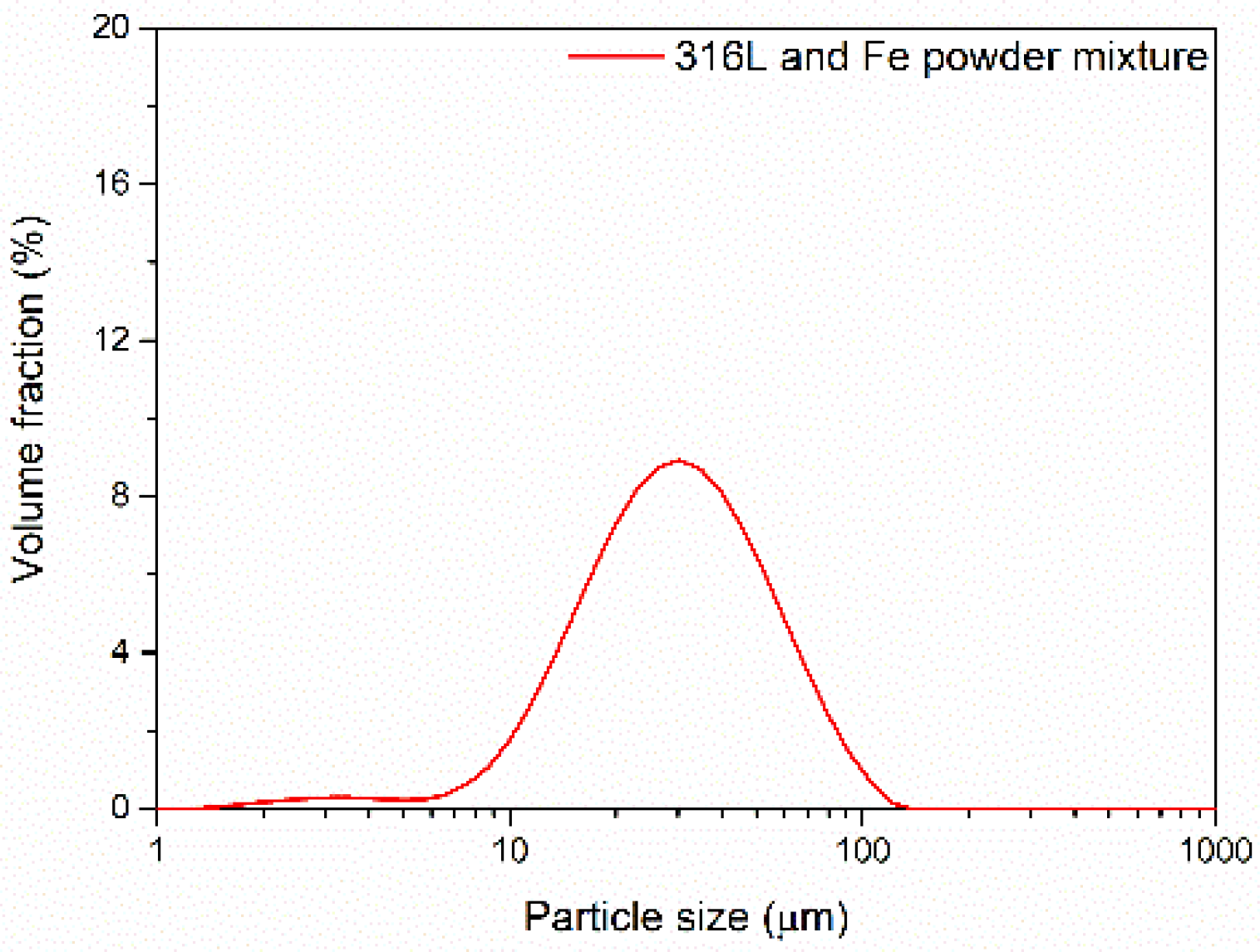
| Powder | d10 (μm) | d50 (μm) | d90 (μm) |
|---|---|---|---|
| Unmixed 316L powder | 23.32 | 58.53 | 112.82 |
| Mixed (hybrid) powder (50% Fe+ 50% 316L steel) | 13.87 | 31.25 | 65.79 |
| Sample Shape | Measuring Technique | Porosity (%) | Relative Density (%) |
|---|---|---|---|
| Square | Optical microscopy | 0.210 | 99.790 |
| Cylindrical | μ-CT | 0.116 | 99.884 |
| Sample | C | Si | Mn | Cr | Mo | Ni | Fe | ||
|---|---|---|---|---|---|---|---|---|---|
| As-Built | 0.0085 | 0.162 | 0.696 | 8.444 | 0.974 | 5.345 | 83.75 | PBF-LB processed alloys | |
| Heat treated | 0.0083 | 0.162 | 0.681 | 8.275 | 0.983 | 5.319 | 83.99 | ||
| Fe | <0.001 | 0.0018 | <0.004 | <0.0079 | 0.0032 | <0.0025 | 99.96 | ||
| 316L steel | 0.015 | 0.306 | 1.406 | 17.00 | 1.965 | 10.67 | 67.57 |
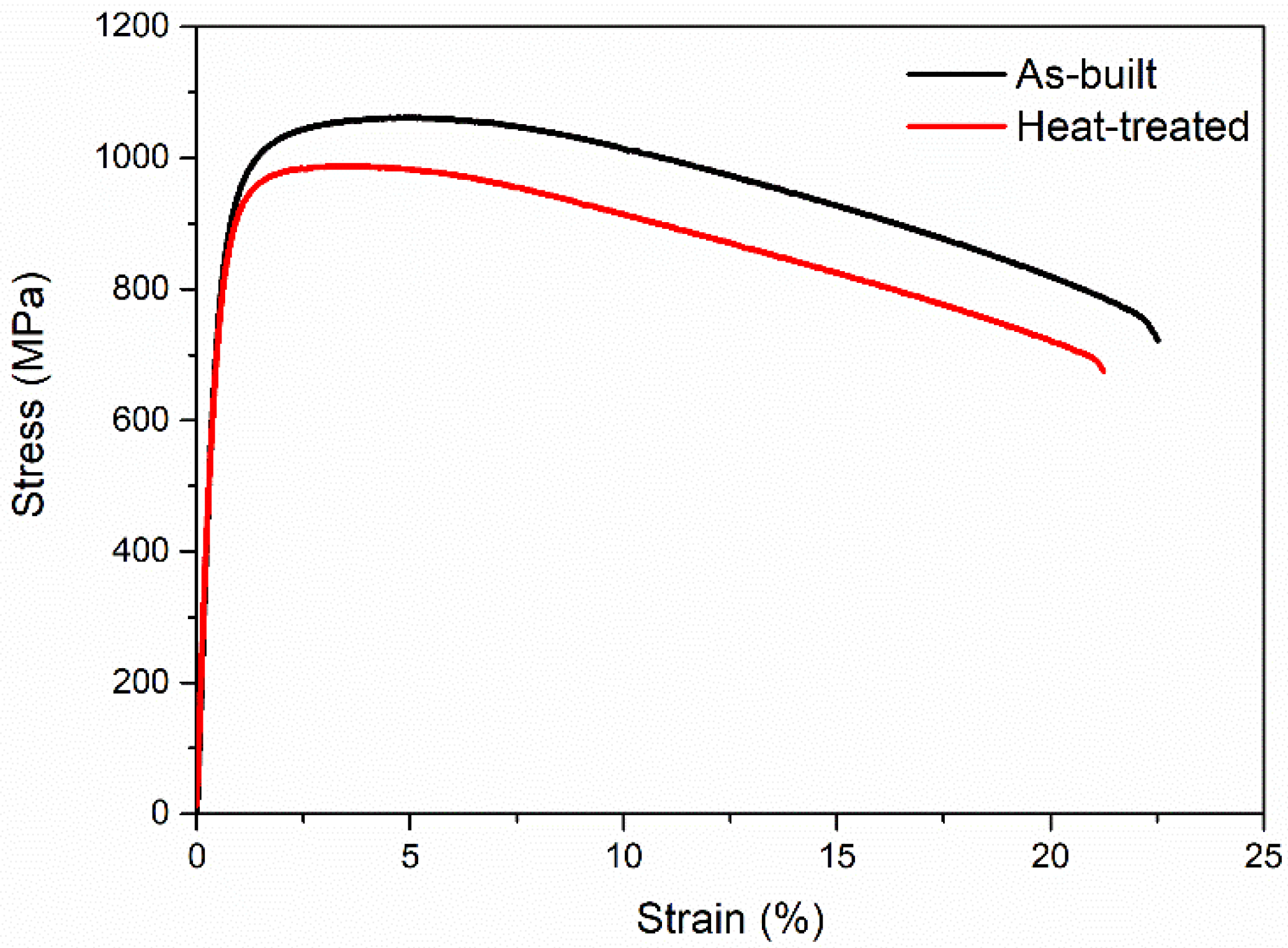
| Sample | Yield Stress (MPa) | Ultimate Tensile Stress (MPa) | Elongation (%) |
|---|---|---|---|
| As-built | 790 | 1060 | 22 |
| Heat-treated | 780 | 985 | 21 |
Disclaimer/Publisher’s Note: The statements, opinions and data contained in all publications are solely those of the individual author(s) and contributor(s) and not of MDPI and/or the editor(s). MDPI and/or the editor(s) disclaim responsibility for any injury to people or property resulting from any ideas, methods, instructions or products referred to in the content. |
© 2023 by the authors. Licensee MDPI, Basel, Switzerland. This article is an open access article distributed under the terms and conditions of the Creative Commons Attribution (CC BY) license (https://creativecommons.org/licenses/by/4.0/).
Share and Cite
Pramanik, S.; Andreiev, A.; Hoyer, K.-P.; Krüger, J.T.; Hengsbach, F.; Kircheis, A.; Zhao, W.; Fischer-Bühner, J.; Schaper, M. Powder Production via Atomisation and Subsequent Laser Powder Bed Fusion Processing of Fe+316L Steel Hybrid Alloy. Powders 2023, 2, 59-74. https://doi.org/10.3390/powders2010005
Pramanik S, Andreiev A, Hoyer K-P, Krüger JT, Hengsbach F, Kircheis A, Zhao W, Fischer-Bühner J, Schaper M. Powder Production via Atomisation and Subsequent Laser Powder Bed Fusion Processing of Fe+316L Steel Hybrid Alloy. Powders. 2023; 2(1):59-74. https://doi.org/10.3390/powders2010005
Chicago/Turabian StylePramanik, Sudipta, Anatolii Andreiev, Kay-Peter Hoyer, Jan Tobias Krüger, Florian Hengsbach, Alexander Kircheis, Weiyu Zhao, Jörg Fischer-Bühner, and Mirko Schaper. 2023. "Powder Production via Atomisation and Subsequent Laser Powder Bed Fusion Processing of Fe+316L Steel Hybrid Alloy" Powders 2, no. 1: 59-74. https://doi.org/10.3390/powders2010005
APA StylePramanik, S., Andreiev, A., Hoyer, K.-P., Krüger, J. T., Hengsbach, F., Kircheis, A., Zhao, W., Fischer-Bühner, J., & Schaper, M. (2023). Powder Production via Atomisation and Subsequent Laser Powder Bed Fusion Processing of Fe+316L Steel Hybrid Alloy. Powders, 2(1), 59-74. https://doi.org/10.3390/powders2010005