
Advances in Microfluidic Synthesis of Solid Catalysts


Abstract
:
1. Introduction
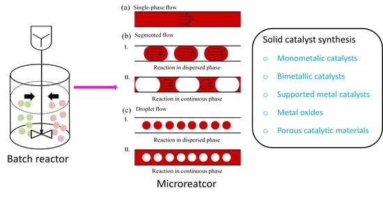
2. Solid Catalyst Synthesis in Batch and Microflow
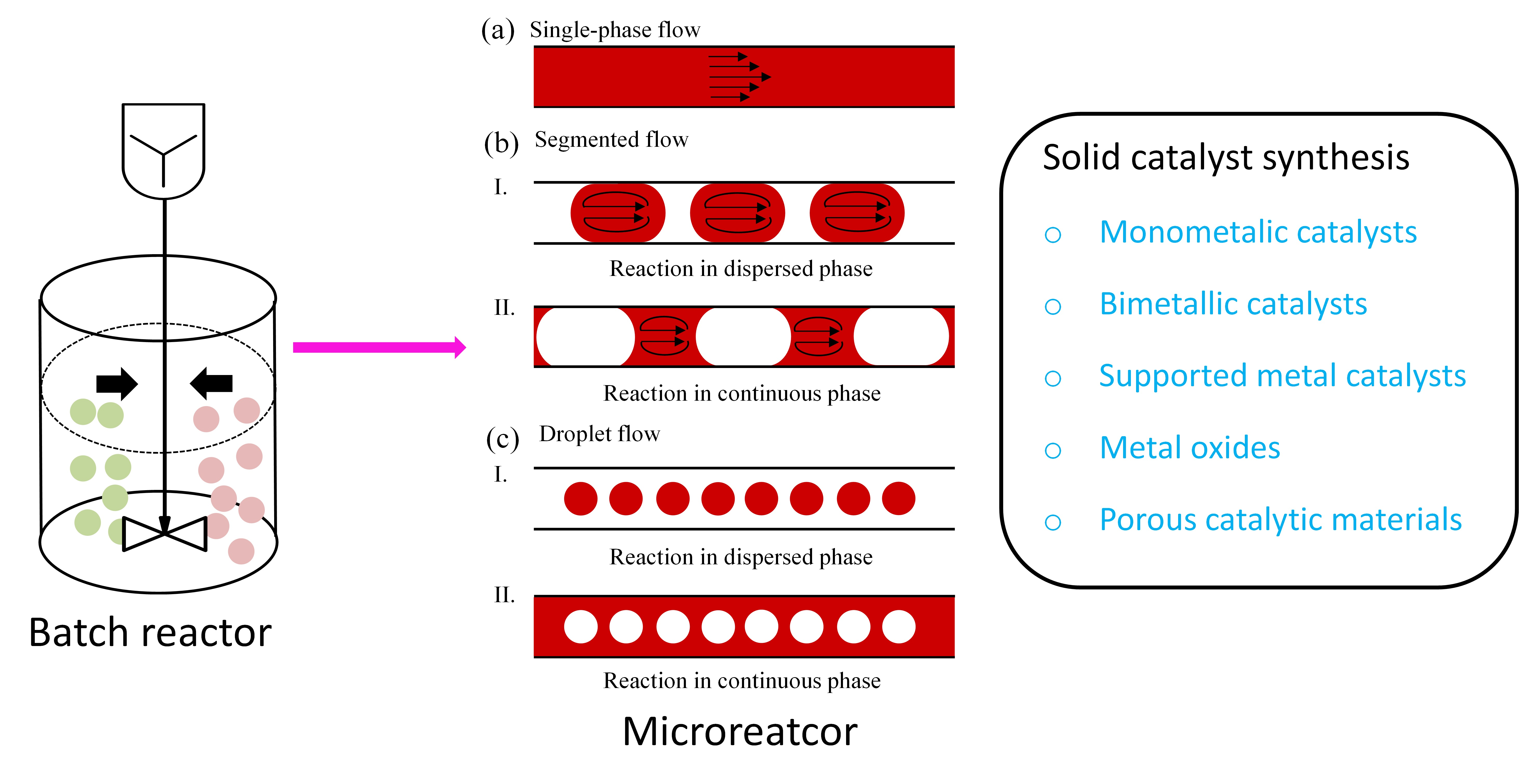
2.1. Synthesis Principle
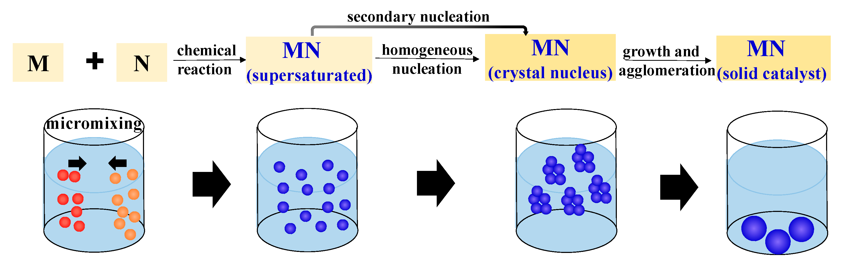
2.2. Batch Processes


| Catalytic Material | Synthesis Method | Reagents | Synthesis Conditions | Size/Morphology | Tested Catalytic Reaction | Ref. |
|---|---|---|---|---|---|---|
| Ni/CeO2 | Precipitation | Ni(NO3)2·6H2O, (NH4)2Ce(NO3)6, Na2CO3, NaOH | pH = 10 | CeO2 (8–12 nm) | Methane oxidative reforming | [70] |
| ZnO | Precipitation | Zn(ac2)·2H2O, NaOH | 60 °C, 2 h | Nanoparticles (≈18 nm) | Congo red dye degradation | [53] |
| MnOx-CeO2 | Precipitation | Ce(NO3)3·6H2O, Mn(CH3COO)2·4H2O, (NH4)2CO3 | 3 h aging at room temperature; 3 h calcination at 350/450 °C | Nanoparticles (8.8–12.1 nm) | NO oxidation | [55] |
| CNT-Cu2O | Precipitation | Carboxylated carbon nanotubes, CuCl, ascorbic acid, NaOH | 1 h stirring at 30 °C | Nanoparticles | p-Nitrophenol reduction | [54] |
| Mn-Ce | Hydrothermal | KMnO4, Ce(NO3)3·6H2O, HCl, Ti-foil | 100 °C for 12 h; 4 h calcination at 350 °C | Microspheres (2–5 μm) | Toluene oxidation | [58] |
| Au-TiO2 | Hydrothermal | Sodium citrate, HAuCl4·4H2O, Ti(OC4H9)4 | 3 h aging; 180 °C for 7 h | Microspheres (≈1.2 µm) | Formaldehyde decomposition | [71] |
| Ni-Ce-ZrOδ | Hydrothermal | Urea, metal salt solutions | 50 h aging at 105 °C; 4 h calcination at 500 °C | CO2 methanation | [57] | |
| FeS2 | Hydrothermal | FeSO4·7H2O, Na2S2O3·5H2O, sulfur | 200 °C for 24 h | Framboids (2.61–3.9 μm) | Diclofenac sodium degradation | [59] |
| Ag | Solvothermal | AgNO3, N,N-dimethylformamide, poly(vinylpyrrolidone) | 140 °C for 8 h | Truncated triangular nanoplates (200 ± 20 nm) | Styrene oxidation | [72] |
| Au-SnO2 | Solvothermal | SnCl4·5H2O, gold chloride, hydrazine | 30 min stirring; 100 °C for 18 h | Nanoparticles | Rhodamine B degradation | [73] |
| TiO2 | Solvothermal | Titanium tetraisopropoxide, ethanol, H2SO4 | 90 °C for 12 h; calcination at 400/450/500 °C | Nanoparticles (near spherical; ≈5 nm) | Methyl orange degradation | [61] |
| Co3O4/Co(OH)2 | Solvothermal | Co(NO3)2·6H2O, KOH, sodium oleate, ethanol, n-hexane | 200 °C for 12 h | Nanocubes (≈14 nm) | Photocatalytic water oxidation | [60] |
| Al-doped ZnO | Sol-gel | Zn(CH3COO)2·2H2O, AlCl3·6H2O, ethanol, diethanol amine | 2 h stirring at room temperature; 1 h calcination at 400 °C | Nanoparticles | Methylene blue dye degradation | [74] |
| Ni-M/Al2O3 (M: Fe, Co, Zr, La and Cu) | Sol-gel | Ni(NO3)2·6H2O, Al(NO3)3·9H2O, M(NO3)X·yH2O, ethanol, propylene oxide | 45 min aging at room temperature; 48 h drying at 85 °C; 3 h calcination at 700 °C | Nanocrystalline | Carbon dioxide methanation | [66] |
| Cu doped TiO2-CNT | Sol-gel | Tetrabutyl-orthotitanate, ethanol, benzyl alcohol, multi-walled carbon nanotubes, Cu(NO3)2·3H2O | 1 h stirring at 0 °C; ultrasonication for 10 min; 1 h calcination at 400 °C | Nanocubes (≈25 nm) | Methylene blue degradation | [64] |
| C@MoSe2 | Sol-gel | MoCl5, diphenyl diselenide, ethanol | 0.5 h ultrasonication; 2 h heating at 700 °C under Ar/H2 | Core-shell nanoparticles (≈200 nm) | Hydrogen evolution reaction | [65] |
| Mn/Fe3O4 | Thermal decomposition | FeSO4·7H2O, oxalic acid, MnSO4·H2O | 1 h calcination at 400 °C | 45.9 nm | Bisphenol A degradation | [69] |
| Fe3O4-Cu | Thermal decomposition | Fe(acetylacetonate)3, Cu(acetylacetonate)2, oleylamine, benzyl ether | 90 min reflux at 110 °C under stirring; 60 min heating at 225 °C | Nanocrystals | 4-Nitrophenol degradation | [75] |
| Co3O4 | Thermal decomposition | CoCl2·2H2O, NaOH | 1 h aging at 50 °C under N2; 2 h calcination at 300 °C | Hexagonal nanoplates (≈100 nm) | p-Nitrophenol reduction | [67] |
| CeO2 | Thermal decomposition | Trimesic acid, 4,4′-bipyridine, dimethyl formamide, Ce(NO3)3·6H2O | 24 h heating at 120 °C, 2 h calcination at 400/500 °C | Nanocrystals | Benzene combustion | [68] |
2.3. Microfluidic Approaches
2.3.1. Advantages of Microfluidic Reactor Technology
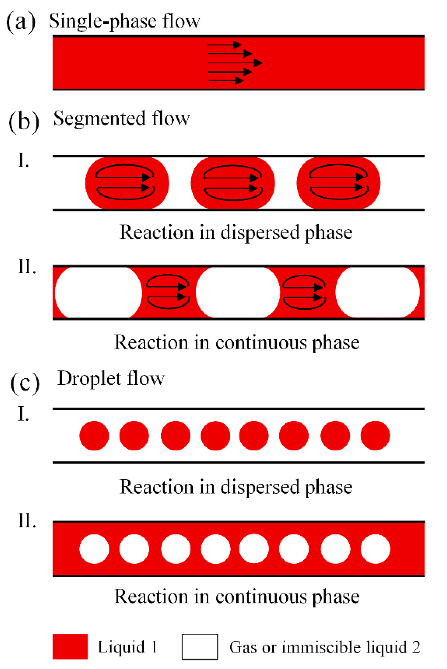
2.3.2. Classification of Microfluidic Methods
2.3.3. Single-Phase Flow Method
2.3.4. Two-Phase Flow Method
3. Examples
3.1. Metal Catalyst
3.1.1. Monometallic Catalyst
3.1.2. Bimetallic Catalyst
3.1.3. Supported Metal Catalyst
| Catalytic Material | Microreactor Material a | Reagents b | Synthesis Conditions | Size/Morphology c | Advantages of Microfludic Method | Tested Catalytic Reaction | Ref. |
|---|---|---|---|---|---|---|---|
| Au | Silicon/glass | HAuCl4·3H2O, NaBH4, PVP | 13 bar N2 | NPs (1.0 ± 0.4 nm) | Efficient mixing; narrow size distribution | CO oxidation | [76] |
| Au | PTFE | HAuCl4·3H2O, trisodium citrate | 70–100 °C, back pressure at 275 kPa | NPs (1.9 ± 0.2 nm) | Enhanced nucleation rate; inhibited particle growth rate | - | [112] |
| Au | PDMS | HAuCl4·4H2O, HEPES, ammonia | 80 μL/min, pH = 7.4 | NPs (88 ± 11 nm) | Precise control of reaction time | Reduction of 4-nitrophenol | [95] |
| Ag | AuNP-SiO2, PVP, AgNO3, HCHO, L-ascorbic acid | pH = 8 | Nanoshells(11.6 ± 5.3 nm) | Large surface to volume ratio; rapid mixing | [98] | ||
| Pd | PEEK and PTFE | H2PdCl4, CTAB, H2Cl6Pt, L-ascorbic acid | 96 °C water bath for 20 min under stirring | Nanocubes (≈14 nm) | Efficient mixing and heat transfer; narrow size distribution | NO2 reduction | [113] |
| Pt | PTFE tube | H2PtCl6, NaOH, THPC | 25–95 °Cthermostatic bath, residence time at 1–5 min | NPs (<2 nm) | Short residence time; high yield and productivity | n-Hexane oxidation | [36] |
| Au-Pd | Silicon/glass | HAuCl4·3H2O, K2PdCl4, NaBH4, PVP | 13 bar N2, ice/water bath | NPs (≈1 nm) | Rapid mixing | CO oxidation | [114] |
| Au-Pd | Silicon | HAuCl4, KBr, PVP, EG, Na2PdCl4 | 8 bar, 160 °C, 120 s; 2 bar, 100 °C, 5 min | NPs (15.1 ± 2.3 nm) | Controlled heat/mass transfer | Ethanol oxidation | [106] |
| Pt-Bi | Bi(NO3)3·5H2O, H2PtCl6·6H2O, PVP, ethanol, EG, PEG | Heat region 200–350 °C | Nanorods(17 nm) | Rapid heat transfer; precise control of temperature | Methanol fuel cells | [35] | |
| Pd@AuPt | PMMA and PSA | Na2PdCl4, K2PtCl4, HAuCl4, L-ascorbic acid, PVP, KBr | 60 °C shaking incubator at 200 rpm | NPs (10–12 nm) | High accuracy and reproducibility | H2O2 synthesis | [115] |
| Ag@Cu2O | PTFE | AgNO3, H2O2, CuSO4·5H2O, SDS, Na3C6H5O7·2H2O, NaBH4, NaOH | Flow rate at 0.25 mL/min + 0.5 mL/min | Ag Cores (20–50 nm) | High efficiency | Methyl orange degradation | [116] |
| PtFeCu/C | Stainless steel | H2PtCl6·6H2O, FeCl3·6H2O, CuCl2·2H2O, EG, H3N·BH3, Nafion, PEG, carbon black | 60 min ultrasonication, 0.5 h stirring | NPs (1.8 ± 0.3 nm) | High throughput | Methanol oxidation | [110] |
| Cu-CuO | Stainless steel | CuSO4, NaBH4, PVP, ammonium hydroxide, NaOH | pH = 10–12, flow rate at 20 mL/min | Nanocomposite (≈10 nm) | Small particle size; narrow size distribution | Methylene blue degradation | [117] |
| Ag3PO4 | PDMS and PMMA | AgNO3, disodium hydrogen phosphate | Flow rate at 130 μL/min | NPs (20–30 nm) | Narrow size distribution; rapid synthesis | Rhodamine B degradation | [118] |
| TiO2 | Stainless steel | TiOSO4, CO(NH2)2 | Heating oil 180 °C, back pressure at 2 MPa | NPs (≈5.0 nm) | Small particle size; even size distribution | Methylene blue decomposition | [119] |
| Catalytic Material | Microreactor a | Reagents b | Synthesis Conditions c | Size/Morphology d | Advantages of Microfluidic Method | Tested Catalytic Reaction | Ref. |
|---|---|---|---|---|---|---|---|
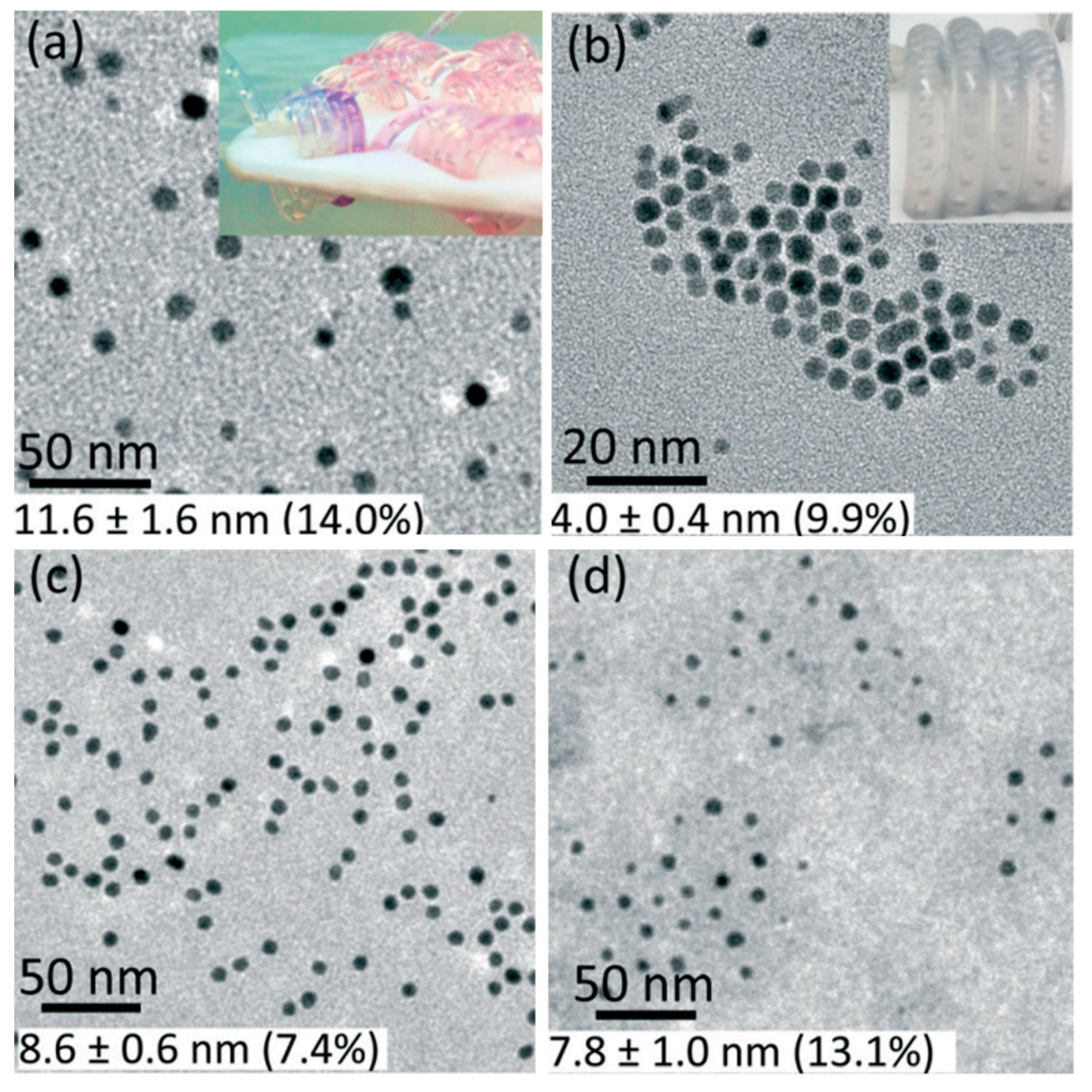
| Au | Glass | HAuCl4, CO gas | Residence time at 3–5 min, room temperature, atmospheric pressure; SF | NPs (3–25 nm) | Large surface-to-volume ratio; high mass transfer | - | [96] |
| Au | PTFE and PEEK | HAuCl4·3H2O, PVP, PP9 ascorbic acid, C12H16O4 | Droplet length at 2.0 mm and distance at 1.33 mm; SF | NPs (2.5–4 nm) | Fast mixing; low concentration gradient | - | [120] |
| Ag | PDMS and Silicon | AgNO3, NaBH4, N2, PVP, NaOH, NH4OH, EDTA, mineral oil | pH = 10–12, room temperature, flow rate at 10–30 mL/h; DF | NPs (7.6 ± 1.8 nm) | Rapid mixing | - | [99] |
| Pd | PTFE and silica | Na2PdCl4, KBr, silicone oil, PVP, L-ascorbic acid | Oil phase flow rate at 180 μL/min, residence time at 6 min; DF | NPs (9.0 ± 1.5 nm) | Fast and efficient mixing; controlled reaction condition | - | [121] |
| Pd | Silicon/Pyrex | Na2PdCl4, PVP, DMF, EG, KBr, air | 0.8 MPa, 180 °C, residence time at 10–120 s; SF | Nanorods (≈4 nm) | Reduced synthesis time | Styrene hydrogenation | [103] |
| Ag, Au | PTFE and silica | AgNO3, NaBH4, HAuCl4·3H2O, trisodium citrate, silicon oil | Ag: residence time 0.6 min; Au: oil bath at 105 °C, residence time: 3–20 min; SF | NPs (Ag: ≈4 nm; Au: 16–17 nm) | Controlled residence time | - | [100] |
| Au@Pd | PTFE and silica | HAuCl4·3H2O, NaBH4, PdCl2, HCl, NaBr, CTAB, CTAC, L-ascorbic acid, sodium citrate, silicone oil | Total flow rate at 0.7 mL/h, oil bath at 55 °C; DF | Core-shell nanostructures (shell thickness: 2.8 nm) | Inline analysis for quick modification of process conditions | - | [107] |
| FePtSn/C | Stainless steel | FeCl2·4H2O, NaBH4, H2PtCl6·6H2O, NMP, PVP SnCl2·2H2O | Reaction and nucleation at 120 °C, Fe/Pt/Sn ratio at 1/1/0.3, particle growth at 30 °C; DF | Alloy NPs (≈2–3 nm; on the carbon surface) | Uniform size distribution | Methanol oxidation | [34] |
| M/TiO2 (M = Pd, Pt or Au) | PTFE and PFA | TiO2, NH3BH3, NaBH4,NaOH, Pd(NO3)2·2H2O, H2PtCl6·6H2O, n-octane, HAuCl4·4H2O | Ultrasonication for 25 min, water bath at 25–80 °C, residence time at 2 min; SF | Noble metal NPs (<5 nm; anchored on TiO2) | Enhanced mixing; small particle size | Ammonia borane hydrolysis | [77] |
| Cu, CuOx | Glass | CuSO4·5H2O, seignette salt, NaOH | pH = 12, 350 °C, 2 h; DF | Microspheres (100–500 μm) | Controlled particle diameter | Hydrogenation; Fenton-like reactions | [122] |
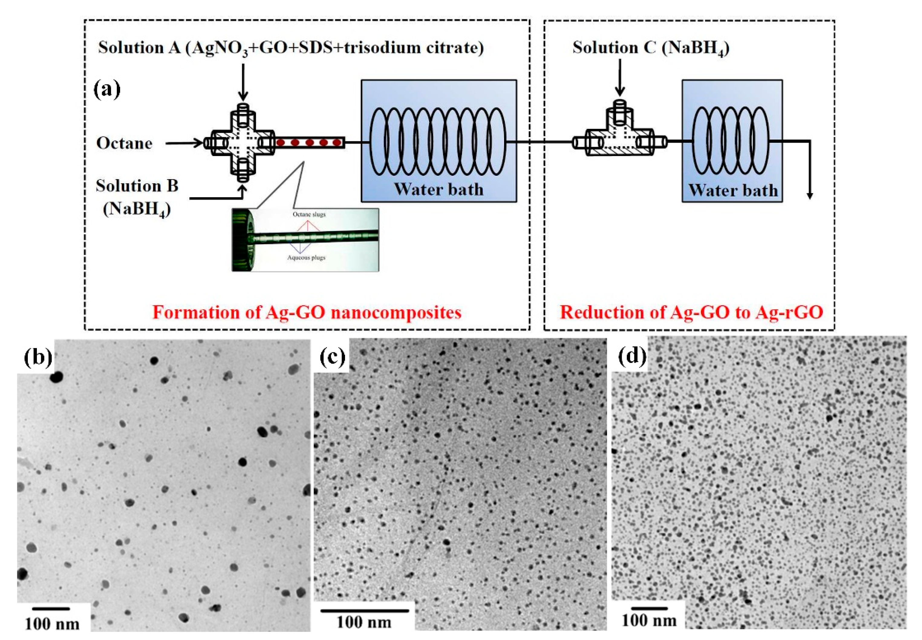
| Ag-rGO | PTFE and PFA | AgNO3, SDS, octane, NaBH4, trisodium citrate | AgNO3:NaBH4 = 1:3 or 1:20; SF | Ag NPs (1.5–5.6 nm) | Precise control of reaction parameters | [111] | |
| Co/rGO | Stainless steel, FEP | CoCl2·6H2O, GO, NaBH4, octane | Water bath at 40 °C; SF | NPs (2.0 ± 0.45 nm) | Improved micromixing | p-Nitrophenol reduction | [123] |
| Fe3O4 | PEEK and PTFE | FeSO4·7H2O, KNO3, NaOH, L-lysine, H2SO4 | 70–110 °C, 1.4 bar; SF | Nanoflakes (30 ± 8 nm) | Accelerated mixing; reduced processing time | - | [124] |
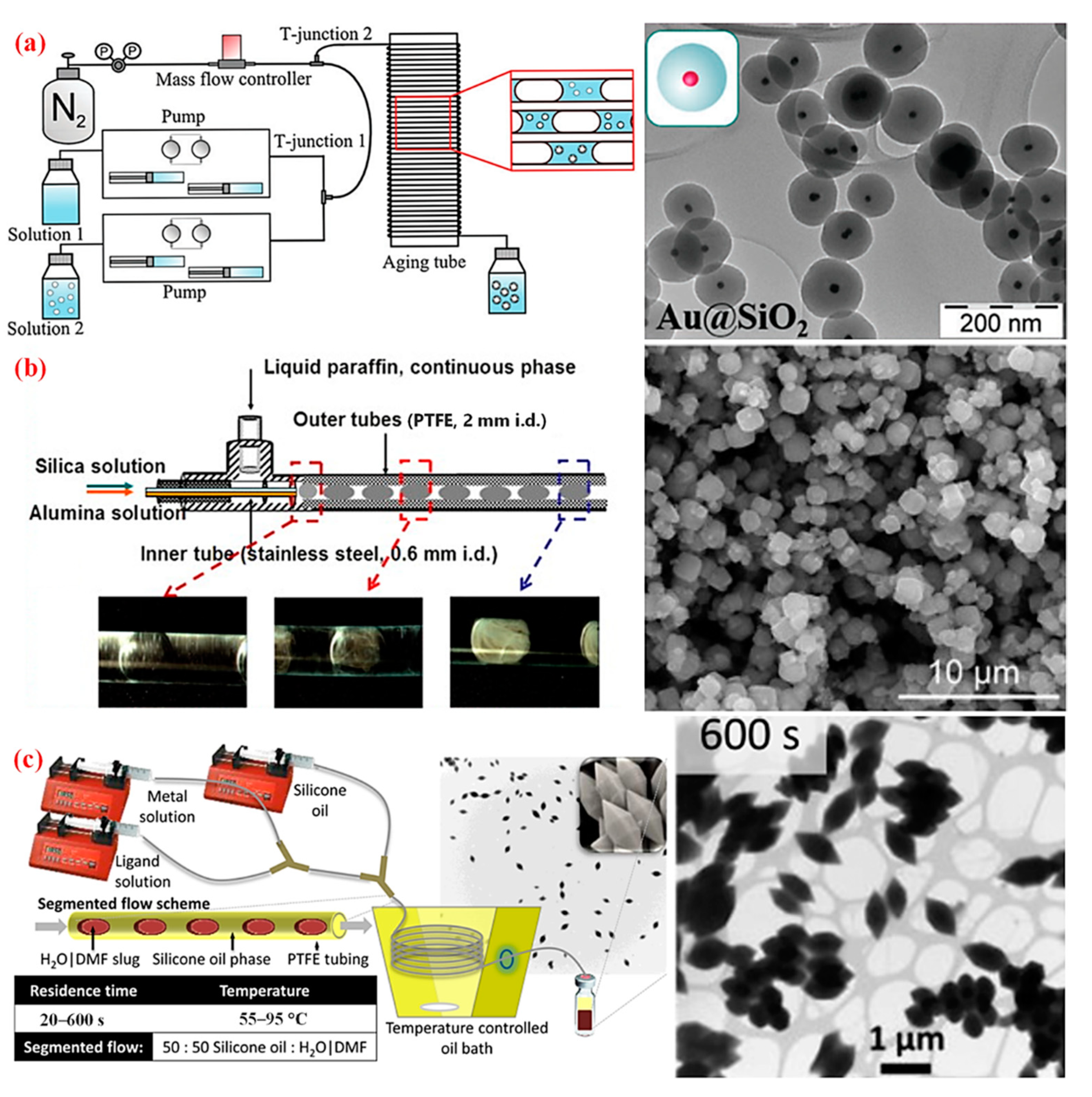
| mSiO2; SiO2@mSiO2; Au@SiO2 | PTFE | NH3(aq), ethanol, TEOS, OTMS | Gas pressure at 1.5 bar; SF | Mesoporous (core-shell) spheres (300–400 nm) | High yield; controlled particle features | - | [125] |
| Zeolite A | PTFE | NaOH, sodium aluminate, sodium silicate | Oil bath at 90 °C; SF | 0.9–1.5 µm | High mixing efficiency; no clogging | - | [126] |
| MOF | PDMS and PFA | Cu(NO3)2·H2O, H3BTC, DMF, ethanol, silicon oil | Silicon oil bath at 90 °C; DF | Octahedral crystals (5–15 µm) | Continuous fabrication; time-saving | - | [42] |
| PMMA-polyDADMAC/Pt | FEP | MMA, EGDMA, DADMAC, AIBN, platinum seed | Water bath at 97 °C; DF | ≈0.7 µm | Fast mixing; short residence time | Azo-dye bleaching | [127] |
3.2. Metal Oxide Catalyst
3.3. Porous Catalytic Material
3.3.1. Silica
3.3.2. Zeolite
3.3.3. MOFs

3.4. Miscellaneous Catalysts
4. Conclusions and Perspectives
Author Contributions
Funding
Conflicts of Interest
References
- Zhou, K.; Li, Y. Catalysis based on nanocrystals with well-defined facets. Angew. Chem. Int. Ed. Engl. 2012, 51, 602–613. [Google Scholar] [CrossRef] [PubMed]
- Cuenya, B.R. Synthesis and catalytic properties of metal nanoparticles: Size, shape, support, composition, and oxidation state effects. Thin Solid Film. 2010, 518, 3127–3150. [Google Scholar] [CrossRef]
- Ludwig, J.R.; Schindler, C.S. Catalyst: Sustainable catalysis. Chemistry 2017, 2, 313–316. [Google Scholar] [CrossRef]
- Hülsey, M.J.; Lim, C.W.; Yan, N. Promoting heterogeneous catalysis beyond catalyst design. Chem. Sci. 2020, 11, 1456–1468. [Google Scholar] [CrossRef] [PubMed]
- Chaturvedi, S.; Dave, P.N.; Shah, N. Applications of nano-catalyst in new era. J. Saudi Chem. Soc. 2012, 16, 307–325. [Google Scholar] [CrossRef]
- Polshettiwar, V.; Varma, R.S. Green chemistry by nano-catalysis. Green Chem. 2010, 12, 743–754. [Google Scholar] [CrossRef]
- Wang, D.; Xie, T.; Li, Y. Nanocrystals: Solution-based synthesis and applications as nanocatalysts. Nano Res. 2009, 2, 30–46. [Google Scholar] [CrossRef]
- Deng, X.; Yue, Y.; Gao, Z. Gas-phase photo-oxidation of organic compounds over nanosized TiO2 photocatalysts by various preparations. Appl. Catal. B-Environ. 2002, 39, 135–147. [Google Scholar] [CrossRef]
- Bell, A.T. The Impact of Nanoscience on Heterogeneous Catalysis. Science 2003, 299, 1688–1691. [Google Scholar] [CrossRef]
- Ghosh Chaudhuri, R.; Paria, S. Core/shell nanoparticles: Classes, properties, synthesis mechanisms, characterization, and applications. Chem. Rev. 2012, 112, 2373–2433. [Google Scholar] [CrossRef]
- Solsona, M.; Vollenbroek, J.C.; Tregouet, C.B.M.; Nieuwelink, A.E.; Olthuis, W.; van den Berg, A.; Weckhuysen, B.M.; Odijk, M. Microfluidics and catalyst particles. Lab Chip 2019, 19, 3575–3601. [Google Scholar] [CrossRef]
- Martin, O.; Bolzli, N.; Puértolas, B.; Pérez-Ramírez, J.; Riedlberger, P. Preparation of highly active phosphated TiO2 catalysts via continuous sol–gel synthesis in a microreactor. Catal. Sci. Technol. 2019, 9, 4744–4758. [Google Scholar] [CrossRef]
- Zhang, F.; Zhang, Y.; Yuan, L.; Gasem, K.A.; Chen, J.; Chiang, F.; Wang, Y.; Fan, M. Synthesis of Cu/Zn/Al/Mg catalysts on methanol production by different precipitation methods. Mol. Catal. 2017, 441, 190–198. [Google Scholar] [CrossRef]
- Xue, Q.; Li, Z.; Chen, M.; Wang, Y.; Yan, B.; Luo, G. Co-precipitation continuous synthesis of the Ni-Rh-Ce0.75Zr0.25O2-δ catalyst in the membrane dispersion microreactor system for n-dodecane steam reforming to hydrogen. Fuel 2021, 297, 120785. [Google Scholar] [CrossRef]
- Chen, H.; Yang, M.; Tao, S.; Chen, G. Template-free synthesis of Co3O4 nanorings and their catalytic application. CrystEngComm 2018, 20, 679–688. [Google Scholar] [CrossRef]
- Chen, H.; Yang, M.; Tao, S.; Ren, M.; Chen, G. Facile synthesis of Co3O4 with different morphologies via oxidation kinetic control and its application in hydrogen peroxide decomposition. Cryst. Growth Des. 2016, 16, 6286–6293. [Google Scholar] [CrossRef]
- Shan, W.; Liu, F.; He, H.; Shi, X.; Zhang, C. The Remarkable Improvement of a Ce-Ti based Catalyst for NOx Abatement, Prepared by a Homogeneous Precipitation Method. ChemCatChem 2011, 3, 1286–1289. [Google Scholar] [CrossRef]
- Na, H.-S.; Shim, J.-O.; Ahn, S.-Y.; Jang, W.-J.; Jeon, K.-W.; Kim, H.-M.; Lee, Y.-L.; Kim, K.-J.; Roh, H.-S. Effect of precipitation sequence on physicochemical properties of CeO2 support for hydrogen production from low-temperature water-gas shift reaction. Int. J. Hydrogen Energy 2018, 43, 17718–17725. [Google Scholar] [CrossRef]
- Phillips, T.W.; Lignos, I.G.; Maceiczyk, R.M.; deMello, A.J.; deMello, J.C. Nanocrystal synthesis in microfluidic reactors: Where next? Lab Chip 2014, 14, 3172–3180. [Google Scholar] [CrossRef]
- Shen, J.; Shafiq, M.; Ma, M.; Chen, H. Synthesis and surface engineering of inorganic nanomaterials based on microfluidic technology. Nanomaterials 2020, 10, 1177. [Google Scholar] [CrossRef]
- Nakashima, T.; Shimizu, M.; Kukizaki, M. Particle control of emulsion by membrane emulsification and its applications. Adv. Drug. Delivery Rev. 2000, 45, 47–56. [Google Scholar] [CrossRef]
- Hakke, V.; Sonawane, S.; Anandan, S.; Sonawane, S.; Ashokkumar, M. Process Intensification Approach Using Microreactors for Synthesizing Nanomaterials—A Critical Review. Nanomaterials 2021, 11, 98. [Google Scholar] [CrossRef] [PubMed]
- Yue, J. Green process intensification using microreactor technology for the synthesis of biobased chemicals and fuels. Chem. Eng. Process 2022, 177, 109002. [Google Scholar] [CrossRef]
- Whitesides, G.M. The origins and the future of microfluidics. Nature 2006, 442, 368–373. [Google Scholar] [CrossRef] [PubMed]
- Niculescu, A.-G.; Chircov, C.; Bîrcă, A.C.; Grumezescu, A.M. Fabrication and applications of microfluidic devices: A review. Int. J. Mol. Sci. 2021, 22, 2011. [Google Scholar] [CrossRef]
- Zhao, C.X.; He, L.; Qiao, S.Z.; Middelberg, A. Nanoparticle synthesis in microreactors. Chem. Eng. Sci. 2011, 66, 1463–1479. [Google Scholar] [CrossRef]
- Nightingale, A.M.; Demello, J.C. Segmented flow reactors for nanocrystal synthesis. Adv. Mater. 2013, 25, 1813–1821. [Google Scholar] [CrossRef]
- Wang, J.; Song, Y. Microfluidic Synthesis of Nanohybrids. Small 2017, 13, 1604084. [Google Scholar] [CrossRef] [PubMed]
- Yao, X.; Zhang, Y.; Du, L.; Liu, J.; Yao, J. Review of the applications of microreactors. Renew. Sustain. Energy Rev. 2015, 47, 519–539. [Google Scholar] [CrossRef]
- Wagner, J.; Köhler, J. Continuous synthesis of gold nanoparticles in a microreactor. Nano Lett. 2005, 5, 685–691. [Google Scholar] [CrossRef]
- Lin, X.Z.; Terepka, A.D.; Yang, H. Synthesis of silver nanoparticles in a continuous flow tubular microreactor. Nano Lett. 2004, 4, 2227–2232. [Google Scholar] [CrossRef]
- Sharada, S.; Suryawanshi, P.L.; Kumar, R.; Gumfekar, S.P.; Narsaiah, T.B.; Sonawane, S.H. Synthesis of palladium nanoparticles using continuous flow microreactor. Colloids Surf. A 2016, 498, 297–304. [Google Scholar] [CrossRef]
- Hossain, M.J.; Rahman, M.; Rahman, M.; Ali, M.; Nandi, N.; Noor, P.; Ahmed, K.; Akhter, S. Optimized reduction conditions for the microfluidic synthesis of 1.3 ± 0.3 nm Pt clusters. J. Nanostruct. Chem. 2016, 6, 49–56. [Google Scholar] [CrossRef]
- Wang, Z.; Fan, H.; Liang, H.; Ma, J.; Li, S.; Song, Y.; Wang, R. Microfluidic synthesis and characterization of FePtSn/C catalysts with enhanced electro-catalytic performance for direct methanol fuel cells. Electrochim. Acta 2017, 230, 245–254. [Google Scholar] [CrossRef]
- Zhang, D.; Wu, F.; Peng, M.; Wang, X.; Xia, D.; Guo, G. One-step, facile and ultrafast synthesis of phase-and size-controlled Pt–Bi intermetallic nanocatalysts through continuous-flow microfluidics. J. Am. Chem. Soc. 2015, 137, 6263–6269. [Google Scholar] [CrossRef]
- Laura, U.; Arruebo, M.; Sebastian, V. Towards the continuous production of Pt-based heterogeneous catalysts using microfluidic systems. Dalton Trans. 2018, 47, 1693–1702. [Google Scholar] [CrossRef]
- Huang, C.; Wang, Y.; Luo, G. Preparation of highly dispersed and small-sized ZnO nanoparticles in a membrane dispersion microreactor and their photocatalytic degradation. Ind. Eng. Chem. Res. 2013, 52, 5683–5690. [Google Scholar] [CrossRef]
- Eskandarloo, H.; Zaferani, M.; Kierulf, A.; Abbaspourrad, A. Shape-controlled fabrication of TiO2 hollow shells toward photocatalytic application. Appl. Catal. B-Environ. 2018, 227, 519–529. [Google Scholar] [CrossRef]
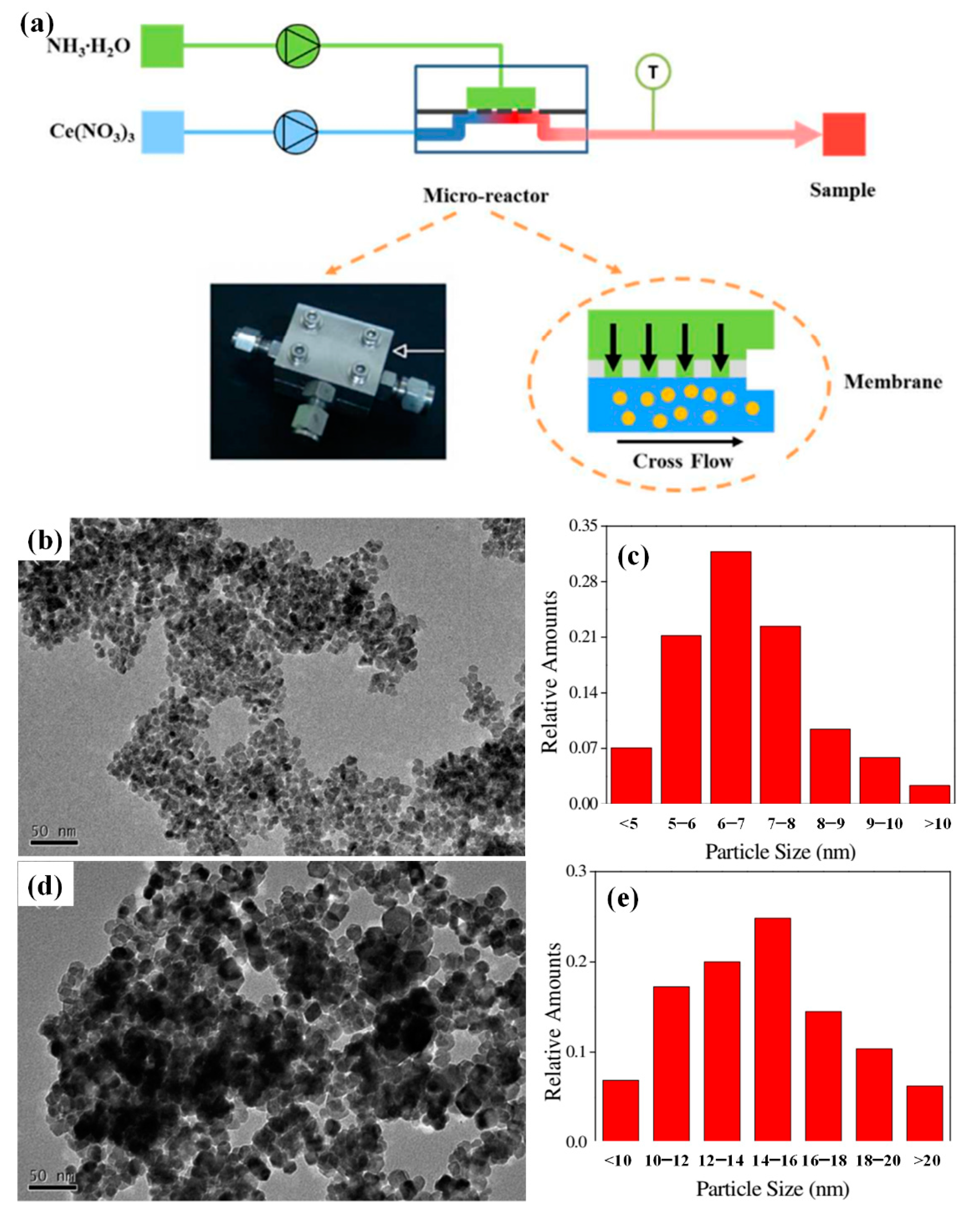
- Yao, H.; Wang, Y.; Luo, G. A size-controllable precipitation method to prepare CeO2 nanoparticles in a membrane dispersion microreactor. Ind. Eng. Chem. Res. 2017, 56, 4993–4999. [Google Scholar] [CrossRef]
- Hoang, P.H.; Yoon, K.-B.; Kim, D.-P. Synthesis of hierarchically porous zeolite A crystals with uniform particle size in a droplet microreactor. RSC Adv. 2012, 2, 5323–5328. [Google Scholar] [CrossRef]
- Echaide-Górriz, C.; Clément, C.; Cacho-Bailo, F.; Téllez, C.; Coronas, J. New strategies based on microfluidics for the synthesis of metal–organic frameworks and their membranes. J. Mater. Chem. A 2018, 6, 5485–5506. [Google Scholar] [CrossRef]
- Faustini, M.; Kim, J.; Jeong, G.-Y.; Kim, J.Y.; Moon, H.R.; Ahn, W.-S.; Kim, D.-P. Microfluidic approach toward continuous and ultrafast synthesis of metal–organic framework crystals and hetero structures in confined microdroplets. J. Am. Chem. Soc. 2013, 135, 14619–14626. [Google Scholar] [CrossRef] [PubMed]
- Yue, J. Multiphase flow processing in microreactors combined with heterogeneous catalysis for efficient and sustainable chemical synthesis. Catal. Today 2018, 308, 3–19. [Google Scholar] [CrossRef]
- Frost, C.G.; Mutton, L. Heterogeneous catalytic synthesis using microreactor technology. Green Chem. 2010, 12, 1687–1703. [Google Scholar] [CrossRef]
- Hao, N.; Nie, Y.; Zhang, J.X. Microfluidic synthesis of functional inorganic micro-/nanoparticles and applications in biomedical engineering. Int. Mater Rev. 2018, 63, 461–487. [Google Scholar] [CrossRef]
- Zong, J.; Yue, J. Continuous Solid Particle Flow in Microreactors for Efficient Chemical Conversion. Ind. Eng. Chem. Res. 2022, 61, 6269–6291. [Google Scholar] [CrossRef]
- Makgwane, P.R.; Ray, S.S. Synthesis of nanomaterials by continuous-flow microfluidics: A review. J. Nanosci. Nanotechnol. 2014, 14, 1338–1363. [Google Scholar] [CrossRef] [PubMed]
- Leubner, I.H. The Balanced Nucleation and Growth (BNG) Model for Controlled Crystal Nucleation and Size in Controlled Precipitations. In Nucleation and Atmospheric Aerosols; Springer: Dordrecht, The Netherlands, 2007; pp. 48–49. [Google Scholar]
- Ring, J. Fundamentals of crystallization: Kinetic effects on particle size distributions and morphology. Chem. Eng. Sci. 1991, 46, 2389–2427. [Google Scholar]
- Lindberg, M.; Rasmuson, Å.C. Reaction crystallization in strained fluid films. Chem. Eng. Sci. 2001, 56, 3257–3273. [Google Scholar] [CrossRef]
- Ren, M.; Yang, M.; Li, S.; Chen, G.; Yuan, Q. High throughput preparation of magnesium hydroxide flame retardant via microreaction technology. RSC Adv. 2016, 6, 92670–92681. [Google Scholar] [CrossRef]
- Koirala, R.; Pratsinis, S.E.; Baiker, A. Synthesis of catalytic materials in flames: Opportunities and challenges. Chem. Soc. Rev. 2016, 45, 3053–3068. [Google Scholar] [CrossRef] [PubMed]
- Adam, R.E.; Pozina, G.; Willander, M.; Nur, O. Synthesis of ZnO nanoparticles by co-precipitation method for solar driven photodegradation of Congo red dye at different pH. Photonics Nanostruct. Fundam. Appl. 2018, 32, 11–18. [Google Scholar] [CrossRef]
- Feng, Y.; Jiao, T.; Yin, J.; Zhang, L.; Zhang, L.; Zhou, J.; Peng, Q. Facile preparation of carbon nanotube-Cu2O nanocomposites as new catalyst materials for reduction of p-nitrophenol. Nanoscale Res. Lett. 2019, 14, 78. [Google Scholar] [CrossRef] [PubMed]
- Shao, J.; Lin, F.; Li, Y.; Tang, H.; Wang, Z.; Liu, P.; Chen, G. Co-precipitation synthesized MnOx-CeO2 mixed oxides for NO oxidation and enhanced resistance to low concentration of SO2 by metal addition. Catalysts 2019, 9, 519. [Google Scholar] [CrossRef]
- Paul, B.; Purkayastha, D.D.; Dhar, S.S. One-pot hydrothermal synthesis and characterization of CoFe2O4 nanoparticles and its application as magnetically recoverable catalyst in oxidation of alcohols by periodic acid. Mater. Chem. Phys. 2016, 181, 99–105. [Google Scholar] [CrossRef]
- Meeyoo, V.; Panchan, N.; Phongprueksathat, N.; Traitangwong, A.; Guo, X.; Li, C.; Rirksomboon, T. Low temperature methanation of CO2 on high Ni content Ni-Ce-ZrOδ catalysts prepared via one-pot hydrothermal synthesis. Catalysts 2020, 10, 32. [Google Scholar] [CrossRef]
- Du, J.; Qu, Z.; Dong, C.; Song, L.; Qin, Y.; Huang, N. Low-temperature abatement of toluene over Mn-Ce oxides catalysts synthesized by a modified hydrothermal approach. Appl. Surf. Sci. 2018, 433, 1025–1035. [Google Scholar] [CrossRef]
- Yu, F.; Wang, Y.; Ma, H.; Zhou, M. Hydrothermal synthesis of FeS2 as a highly efficient heterogeneous electro-Fenton catalyst to degrade diclofenac via molecular oxygen effects for Fe (II)/Fe (III) cycle. Sep. Purif. Technol. 2020, 248, 117022. [Google Scholar] [CrossRef]
- Yang, B.; Xie, W.; Wang, G.; Wang, Z.; Zhao, X.; Yang, C.; Su, X.; Ma, K. One-step solvothermal synthesis of Co3O4/Co(OH)2 hybrids as a catalyst for visible-light-driven water oxidation. Mater. Lett. 2020, 262, 127170. [Google Scholar] [CrossRef]
- Ramakrishnan, V.M.; Natarajan, M.; Santhanam, A.; Asokan, V.; Velauthapillai, D. Size controlled synthesis of TiO2 nanoparticles by modified solvothermal method towards effective photo catalytic and photovoltaic applications. Mater. Res. Bull. 2018, 97, 351–360. [Google Scholar] [CrossRef]
- Zhang, X.-F.; Wang, A.-J.; Zhang, L.; Yuan, J.; Li, Z.; Feng, J.-J. Solvothermal synthesis of monodisperse PtCu dodecahedral nanoframes with enhanced catalytic activity and durability for hydrogen evolution reaction. ACS Appl. Energy Mater. 2018, 1, 5054–5061. [Google Scholar] [CrossRef]
- Esposito, S. “Traditional” Sol-Gel Chemistry as a Powerful Tool for the Preparation of Supported Metal and Metal Oxide Catalysts. Materials 2019, 12, 668. [Google Scholar] [CrossRef] [PubMed]
- Shafei, A.; Sheibani, S. Visible light photocatalytic activity of Cu doped TiO2-CNT nanocomposite powder prepared by sol–gel method. Mater. Res. Bull. 2019, 110, 198–206. [Google Scholar] [CrossRef]
- Ren, X.; Yao, Y.; Ren, P.; Wang, Y.; Peng, Y. Facile sol-gel synthesis of C@MoSe2 core-shell composites as advanced hydrogen evolution reaction catalyst. Mater. Lett. 2019, 238, 286–289. [Google Scholar] [CrossRef]
- Moghaddam, S.V.; Rezaei, M.; Meshkani, F.; Daroughegi, R. Carbon dioxide methanation over Ni-M/Al2O3 (M: Fe, CO, Zr, La and Cu) catalysts synthesized using the one-pot sol-gel synthesis method. Int. J. Hydrogen Energy 2018, 43, 16522–16533. [Google Scholar] [CrossRef]
- Chen, H.; Yang, M.; Tao, S.; Chen, G. Oxygen vacancy enhanced catalytic activity of reduced Co3O4 towards p-nitrophenol reduction. Appl. Catal. B-Environ. 2017, 209, 648–656. [Google Scholar] [CrossRef]
- Zheng, J.; Wang, Z.; Chen, Z.; Zuo, S. Mechanism of CeO2 synthesized by thermal decomposition of Ce-MOF and its performance of benzene catalytic combustion. J. Rare Earths 2021, 39, 790–796. [Google Scholar] [CrossRef]
- Du, J.; Bao, J.; Liu, Y.; Kim, S.H.; Dionysiou, D.D. Facile preparation of porous Mn/Fe3O4 cubes as peroxymonosulfate activating catalyst for effective bisphenol A degradation. Chem. Eng. J. 2019, 376, 119193. [Google Scholar] [CrossRef]
- Asencios, Y.J.; Elias, K.F.; de Zawadzki, A.; Assaf, E.M. Synthesis-Gas Production from Methane over Ni/CeO2 Catalysts Synthesized by Co-Precipitation Method in Different Solvents. Methane 2022, 1, 72–81. [Google Scholar] [CrossRef]
- Yu, J.; Yue, L.; Liu, S.; Huang, B.; Zhang, X. Hydrothermal preparation and photocatalytic activity of mesoporous Au–TiO2 nanocomposite microspheres. J. Colloid Interface Sci. 2009, 334, 58–64. [Google Scholar] [CrossRef]
- Xu, R.; Wang, D.; Zhang, J.; Li, Y. Shape-dependent catalytic activity of silver nanoparticles for the oxidation of styrene. Chem. Asian J. 2006, 1, 888–893. [Google Scholar] [CrossRef] [PubMed]
- Babu, B.; Koutavarapu, R.; Harish, V.; Shim, J.; Yoo, K. Novel in-situ synthesis of Au/SnO2 quantum dots for enhanced visible-light-driven photocatalytic applications. Ceram. Int. 2019, 45, 5743–5750. [Google Scholar] [CrossRef]
- Islam, M.R.; Rahman, M.; Farhad, S.; Podder, J. Structural, optical and photocatalysis properties of sol–gel deposited Al-doped ZnO thin films. Surf. Interfaces 2019, 16, 120–126. [Google Scholar] [CrossRef]
- Zhao, W.; Yang, S.; Guo, C.; Yang, J.; Liu, Y. One-step fabrication of Fe3O4–Cu nanocomposites: High-efficiency and low-cost catalysts for reduction of 4-nitrophenol. Mater. Chem. Phys. 2021, 260, 124144. [Google Scholar] [CrossRef]
- Tofighi, G.; Lichtenberg, H.; Pesek, J.; Sheppard, T.L.; Wang, W.; Schöttner, L.; Rinke, G.; Dittmeyer, R.; Grunwaldt, J.-D. Continuous microfluidic synthesis of colloidal ultrasmall gold nanoparticles: In situ study of the early reaction stages and application for catalysis. React. Chem. Eng. 2017, 2, 876–884. [Google Scholar] [CrossRef]
- Luo, L.; Yang, M.; Chen, G. Continuous synthesis of TiO2-supported noble metal nanoparticles and their application in ammonia borane hydrolysis. Chem. Eng. Sci. 2022, 251, 117479. [Google Scholar] [CrossRef]
- Abelló, S.; Pérez-Ramírez, J. Tuning Nanomaterials’ Characteristics by a Miniaturized In-Line Dispersion–Precipitation Method: Application to Hydrotalcite Synthesis. Adv. Mater. 2006, 18, 2436–2439. [Google Scholar] [CrossRef]
- NaderiNasrabadi, M.; Mortazavi, Y.; Khodadadi, A.A. Highly sensitive and selective Gd2O3-doped SnO2 ethanol sensors synthesized by a high temperature and pressure solvothermal method in a microreactor. Sens. Actuators B 2016, 230, 130–139. [Google Scholar] [CrossRef]
- Ling, F.W.; Abdulbari, H.A.; Chin, S.-Y. Synthesis and characteristics of silica nano-particles using modified sol–gel method in microreactor. Mater. Today Proc. 2021, 42, 7. [Google Scholar] [CrossRef]
- Marre, S.; Jensen, K.F. Synthesis of micro and nanostructures in microfluidic systems. Chem. Soc. Rev. 2010, 39, 1183–1202. [Google Scholar] [CrossRef]
- Song, H.; Chen, D.L.; Ismagilov, R.F. Reactions in droplets in microfluidic channels. Angew. Chem. Int. Ed. Engl. 2006, 45, 7336–7356. [Google Scholar] [CrossRef]
- Zhou, P.; He, J.; Huang, L.; Yu, Z.; Zhou, J. Microfluidic High-Throughput Platforms for Discovery of Novel Materials. Nanomaterials 2020, 10, 2514. [Google Scholar] [CrossRef]
- Grumezescu, A.M. Nanomaterials Synthesis through Microfluidic Methods: An Updated Overview. Nanomaterials 2021, 11, 864. [Google Scholar]
- Li, G.X.; Li, Q.; Cheng, R.; Chen, S. Synthesis of quantum dots based on microfluidic technology. Curr. Opin. Chem. Eng. 2020, 29, 34–41. [Google Scholar] [CrossRef]
- Gonidec, M.; Puigmartí-Luis, J. Continuous- versus Segmented-Flow Microfluidic Synthesis in Materials Science. Crystals 2018, 9, 12. [Google Scholar] [CrossRef]
- Liu, Z.M.; Yang, Y.; Du, Y.; Pang, Y. Advances in Droplet-Based Microfluidic Technology and Its Applications. Chin. J. Anal. Chem. 2017, 45, 282–296. [Google Scholar] [CrossRef]
- He, Y.; Kim, K.J.; Chang, C. Segmented Microfluidic Flow Reactors for Nanomaterial Synthesis. Nanomaterials 2020, 10, 1421. [Google Scholar] [CrossRef]
- Liu, L.; Xiang, N.; Ni, Z. Droplet-based microreactor for the production of micro/nano-materials. Electrophoresis 2020, 41, 833–851. [Google Scholar] [CrossRef]
- Gao, C.; Lyu, F.; Yin, Y. Encapsulated metal nanoparticles for catalysis. Chem. Rev. 2020, 121, 834–881. [Google Scholar] [CrossRef]
- Narayan, N.; Meiyazhagan, A.; Vajtai, R. Metal nanoparticles as green catalysts. Materials 2019, 12, 3602. [Google Scholar] [CrossRef]
- Rodrigues, T.S.; da Silva, A.G.; Camargo, P.H. Nanocatalysis by noble metal nanoparticles: Controlled synthesis for the optimization and understanding of activities. J. Mater. Chem. A 2019, 7, 5857–5874. [Google Scholar] [CrossRef]
- Jamkhande, P.G.; Ghule, N.W.; Bamer, A.H.; Kalaskar, M.G. Metal nanoparticles synthesis: An overview on methods of preparation, advantages and disadvantages, and applications. J. Drug Deliv. Sci. Technol. 2019, 53, 101174. [Google Scholar] [CrossRef]
- Li, X.; Yang, X.; Huang, Y.; Zhang, T.; Liu, B. Supported noble-metal single atoms for heterogeneous catalysis. Adv. Mater. 2019, 31, 1902031. [Google Scholar] [CrossRef]
- Fu, Q.; Fu, C.; Teng, L.; Li, W.; Handschuh-Wang, S. Rapid synthesis and growth process deconvolution of Au nanoflowers with ultrahigh catalytic activity based on microfluidics. J. Mater. Sci. 2021, 56, 12. [Google Scholar] [CrossRef]
- Huang, H.; du Toit, H.; Ben-Jaber, S.; Wu, G.; Panariello, L.; Thanh, N.T.K.; Parkin, I.P.; Gavriilidis, A. Rapid synthesis of gold nanoparticles with carbon monoxide in a microfluidic segmented flow system. React. Chem. Eng. 2019, 4, 884–890. [Google Scholar] [CrossRef]
- Kang, W.J.; Cheng, C.Q.; Li, Z.; Feng, Y.; Shen, G.R.; Du, X.W. Ultrafine Ag nanoparticles as active catalyst for electrocatalytic hydrogen production. ChemCatChem 2019, 11, 5976–5981. [Google Scholar] [CrossRef]
- Watanabe, S.; Miyahara, M.T. Flow synthesis of silver nanoshells using a microreactor. Chem. Eng. J. 2019, 374, 674–683. [Google Scholar]
- Xu, L.; Peng, J.; Yan, M.; Zhang, D.; Shen, A.Q. Droplet synthesis of silver nanoparticles by a microfluidic device. Chem. Eng. Process. Process Intensif. 2016, 102, 186–193. [Google Scholar] [CrossRef]
- Ochoa-Vazquez, G.; Kharisov, B.; Arizmendi-Morquecho, A.; Cario, A.; Aymonier, C.; Marre, S.; López, I. Continuous Segmented-Flow Synthesis of Ag and Au Nanoparticles Using a Low Cost Microfluidic PTFE Tubing Reactor. IEEE Trans. Nanobiosci. 2021, 21, 135–140. [Google Scholar] [CrossRef]
- Lin, L.; Yao, S.; Gao, R.; Liang, X.; Yu, Q.; Deng, Y.; Liu, J.; Peng, M.; Jiang, Z.; Li, S. A highly CO-tolerant atomically dispersed Pt catalyst for chemoselective hydrogenation. Nat. Nanotechnol. 2019, 14, 354–361. [Google Scholar] [CrossRef] [PubMed]
- Ding, Y.; Wu, Q.; Lin, B.; Guo, Y.; Guo, Y.; Wang, Y.; Wang, L.; Zhan, W. Superior catalytic activity of a Pd catalyst in methane combustion by fine-tuning the phase of ceria-zirconia support. Appl. Catal. B-Environ. 2020, 266, 118631. [Google Scholar] [CrossRef]
- Sebastian, V.; Basak, S.; Jensen, K.F. Continuous synthesis of palladium nanorods in oxidative segmented flow. AIChE J. 2016, 62, 373–380. [Google Scholar] [CrossRef]
- Huang, J.; Mensi, M.; Oveisi, E.; Mantella, V.; Buonsanti, R. Structural sensitivities in bimetallic catalysts for electrochemical CO2 reduction revealed by Ag–Cu nanodimers. J. Am. Chem. Soc. 2019, 141, 2490–2499. [Google Scholar] [CrossRef]
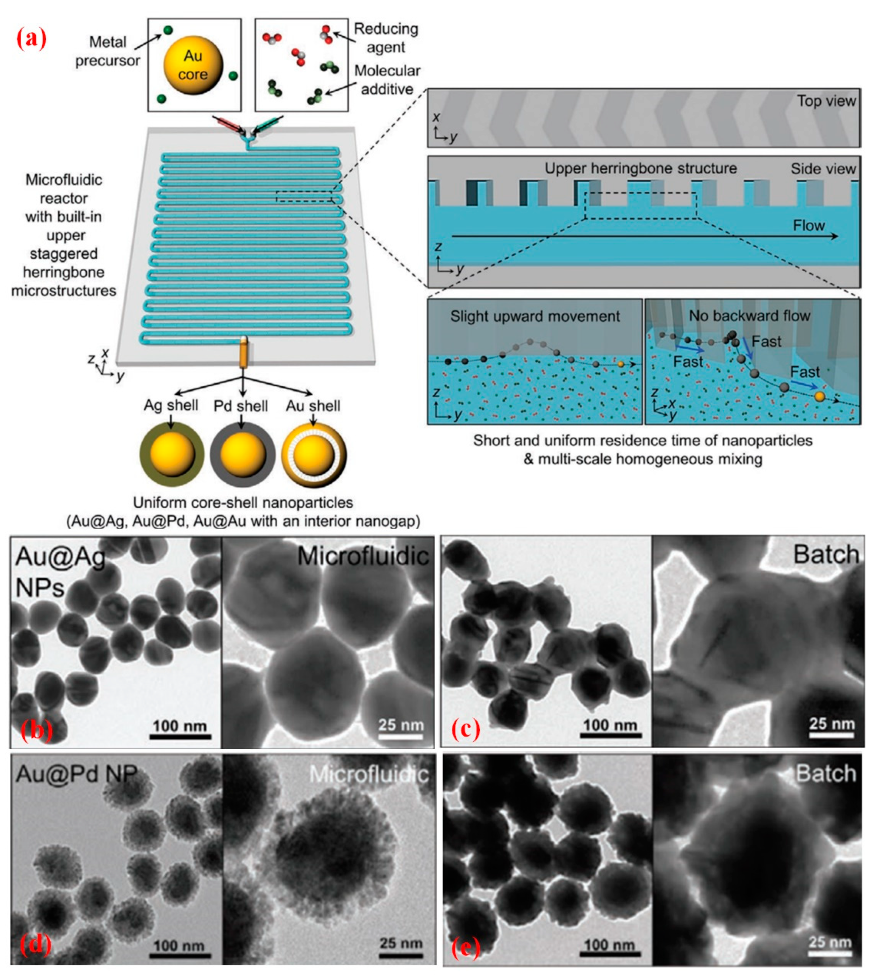
- Shin, Y.; Lim, Y.; Kwak, T.; Hwang, J.H.; Georgescu, A.; Huh, D.; Kim, D.; Kang, T. Microfluidic Multi-Scale Homogeneous Mixing with Uniform Residence Time Distribution for Rapid Production of Various Metal Core–Shell Nanoparticles. Adv. Funct. Mater. 2020, 31, 2007856. [Google Scholar] [CrossRef]
- Sebastian, V.; Zaborenko, N.; Gu, L.; Jensen, K.F. Microfluidic assisted synthesis of hybrid Au–pd dumbbell-like nanostructures: Sequential addition of reagents and ultrasonic radiation. Cryst. Growth Des. 2017, 17, 2700–2710. [Google Scholar] [CrossRef]
- Santana, J.S.; Koczkur, K.M.; Skrabalak, S.E. Synthesis of Core@ Shell nanostructures in a continuous flow droplet reactor: Controlling structure through relative flow rates. Langmuir 2017, 33, 6054–6061. [Google Scholar] [CrossRef]
- Rezaei, F.; Dinari, M. Novel covalent organic polymer-supported Ag nanoparticles as a catalyst for nitroaromatics reduction. Colloids Surf. A 2021, 618, 126441. [Google Scholar] [CrossRef]
- Zhang, X.; Chen, K.H.; Zhou, Z.H.; He, L.N. Reduced graphene oxide supported Ag nanoparticles: An efficient catalyst for CO2 conversion at ambient conditions. ChemCatChem 2020, 12, 4825–4830. [Google Scholar] [CrossRef]
- Zhou, Y.; Wang, D.; Kang, X.; Zhang, D.; Guo, G. A Scalable Synthesis of Ternary Nanocatalysts for High Efficiency Electrooxidation Catalysis by Microfluidics. Nanoscale 2020, 12, 12647–12654. [Google Scholar] [CrossRef]
- Tao, S.; Yang, M.; Chen, H.; Chen, G. Continuous Synthesis of Highly Uniform Noble Metal Nanoparticles over Reduced Graphene Oxide Using Microreactor Technology. ACS Sustain. Chem. Eng. 2018, 6, 8719–8726. [Google Scholar] [CrossRef]
- Huang, H.; du Toit, H.; Besenhard, M.O.; Ben-Jaber, S.; Dobson, P.; Parkin, I.; Gavriilidis, A. Continuous flow synthesis of ultrasmall gold nanoparticles in a microreactor using trisodium citrate and their SERS performance. Chem. Eng. Sci. 2018, 189, 422–430. [Google Scholar] [CrossRef]
- Pekkari, A.; Say, Z.; Susarrey-Arce, A.; Langhammer, C.; Härelind, H.; Sebastian, V.; Moth-Poulsen, K. Continuous Microfluidic Synthesis of Pd Nanocubes and PdPt Core–Shell Nanoparticles and Their Catalysis of NO2 Reduction. ACS Appl. Mater. Interfaces 2019, 11, 36196–36204. [Google Scholar] [CrossRef] [PubMed]
- Tofighi, G.; Gaur, A.; Doronkin, D.E.; Lichtenberg, H.; Wang, W.; Wang, D.; Rinke, G.N.; Ewinger, A.; Dittmeyer, R.; Grunwaldt, J.-D. Microfluidic synthesis of ultrasmall AuPd nanoparticles with a homogeneously mixed alloy structure in fast continuous flow for catalytic applications. J. Phys. Chem. C 2018, 122, 1721–1731. [Google Scholar] [CrossRef]
- Van Nguyen, H.; Kim, K.Y.; Nam, H.; Lee, S.Y.; Yu, T.; Seo, T.S. Centrifugal microfluidic device for the high-throughput synthesis of Pd@ AuPt core–shell nanoparticles to evaluate the performance of hydrogen peroxide generation. Lab Chip 2020, 20, 3293–3301. [Google Scholar] [CrossRef]
- Tao, S.; Yang, M.; Chen, H.; Ren, M.; Chen, G. Microfluidic synthesis of Ag@Cu2O core-shell nanoparticles with enhanced photocatalytic activity. J. Colloid. Interface Sci. 2017, 486, 16–26. [Google Scholar] [CrossRef] [PubMed]
- Xu, L.; Srinivasakannan, C.; Peng, J.; Zhang, L.; Zhang, D. Synthesis of Cu-CuO nanocomposite in microreactor and its application to photocatalytic degradation. J. Alloys Compd. 2017, 695, 263–269. [Google Scholar] [CrossRef]
- Singh, A.; Baruah, A.; Katoch, V.; Vaghasiya, K.; Prakash, B.; Ganguli, A.K. Continuous flow synthesis of Ag3PO4 nanoparticles with greater photostability and photocatalytic dye degradation efficiency. J. Photochem. Photobiol. A 2018, 364, 382–389. [Google Scholar] [CrossRef]
- Deng, N.; Wang, Y.; Luo, G. A novel method for fast and continuous preparation of superfine titanium dioxide nanoparticles in microfluidic system. Particuology 2022, 60, 61–67. [Google Scholar] [CrossRef]
- Hafermann, L.; Michael Köhler, J. Small gold nanoparticles formed by rapid photochemical flow-through synthesis using microfluid segment technique. J. Nanopart. Res. 2015, 17, 99. [Google Scholar] [CrossRef]
- Kim, Y.H.; Zhang, L.; Yu, T.; Jin, M.; Qin, D.; Xia, Y. Droplet-based microreactors for continuous production of palladium nanocrystals with controlled sizes and shapes. Small 2013, 9, 3462–3467. [Google Scholar] [CrossRef]
- Ding, Y.; Yan, Y.; Wang, H.; Wang, X.; Hu, T.; Tao, S.; Li, G. Preparation of Hollow Cu and CuOx Microspheres with a Hierarchical Structure for Heterogeneous Catalysis. ACS Appl. Mater. Interfaces 2018, 10, 41793–41801. [Google Scholar] [CrossRef]
- Yang, M.; Luo, L.; Chen, G. Microfluidic synthesis of ultrasmall Co nanoparticles over reduced graphene oxide and their catalytic properties. AIChE J. 2020, 66, e16950. [Google Scholar] [CrossRef]
- Larrea, A.; Sebastian, V.; Ibarra, A.; Arruebo, M.; Santamaria, J. Gas slug microfluidics: A unique tool for ultrafast, highly controlled growth of iron oxide nanostructures. Chem. Mater. 2015, 27, 4254–4260. [Google Scholar] [CrossRef]
- Knossalla, J.; Mezzavilla, S.; Schüth, F. Continuous synthesis of nanostructured silica based materials in a gas–liquid segmented flow tubular reactor. New J. Chem. 2016, 40, 4361–4366. [Google Scholar] [CrossRef]
- Yu, L.; Pan, Y.; Wang, C.; Zhang, L. A two-phase segmented microfluidic technique for one-step continuous versatile preparation of zeolites. Chem. Eng. J. 2013, 219, 78–85. [Google Scholar] [CrossRef]
- Li, X.; Visaveliya, N.; Hafermann, L.; Gross, G.A.; Knauer, A.; Koehler, J.M. Hierarchically structured particles for micro flow catalysis. Chem. Eng. J. 2017, 326, 1058–1065. [Google Scholar] [CrossRef]
- Nayak, R.; Ali, F.A.; Mishra, D.K.; Ray, D.; Aswal, V.; Sahoo, S.K.; Nanda, B. Fabrication of CuO nanoparticle: An efficient catalyst utilized for sensing and degradation of phenol. J. Mater. Res. Technol. 2020, 9, 11045–11059. [Google Scholar] [CrossRef]
- Li, F.; Wan, L.; Wang, Y.; Wang, Y. Template-free method for the synthesis of high-pore-volume γ-Al2O3 nanofibers in a membrane dispersion microreactor. Nanotechnology 2021, 32, 185601. [Google Scholar] [CrossRef]
- Baruah, A.; Jindal, A.; Acharya, C.; Prakash, B.; Basu, S.; Ganguli, A.K. Microfluidic reactors for the morphology controlled synthesis and photocatalytic study of ZnO nanostructures. J. Micromech. Microeng. 2017, 27, 035013. [Google Scholar] [CrossRef]
- Yao, H.; Wang, Y.; Jing, Y.; Luo, G. Ultrafast, Continuous and Shape-Controlled Preparation of CeO2 Nanostructures: Nanorods and Nanocubes in a Microfluidic System. Ind. Eng. Chem. Res. 2018, 57, 7525–7532. [Google Scholar] [CrossRef]
- Periyasamy, M.; Saha, A.; Sain, S.; Mandal, M.; Kar, A. A comparative structural and photocatalytic study on SnO2 nanoparticles fabricated in batch reactor and microreactor. J. Environ. Chem. Eng. 2020, 8, 104604. [Google Scholar] [CrossRef]
- Liang, J.; Liang, Z.; Zou, R.; Zhao, Y. Heterogeneous catalysis in zeolites, mesoporous silica, and metal–organic frameworks. Adv. Mater. 2017, 29, 1701139. [Google Scholar] [CrossRef] [PubMed]
- Hao, N.; Nie, Y.; Zhang, J. Microfluidics for Silica Biomaterials Synthesis: Opportunities and Challenges. Biomater. Sci. 2019, 7, 2218–2240. [Google Scholar] [CrossRef]
- He, Y.; Kim, K.-J.; Chang, C.-H. Continuous, size and shape-control synthesis of hollow silica nanoparticles enabled by a microreactor-assisted rapid mixing process. Nanotechnology 2017, 28, 235602. [Google Scholar] [CrossRef] [PubMed]
- Wang, J.; Guo, Z.; Zhao, J.; Yang, Q.; Dai, Y.; Yang, Y.; Wang, C. Preparation of silica as catalyst supports with controlled surface property using continuous flow reactor. Appl. Catal. A 2019, 585, 117212. [Google Scholar] [CrossRef]
- Wang, Y.; Wang, C.; Wang, L.; Wang, L.; Xiao, F.-S. Zeolite fixed metal nanoparticles: New perspective in catalysis. Acc. Chem. Res. 2021, 54, 2579–2590. [Google Scholar] [CrossRef]
- Yang, J.; Yang, Y.W. Metal–organic frameworks for biomedical applications. Small 2020, 16, 1906846. [Google Scholar] [CrossRef]
- Paseta, L.; Seoane, B.; Julve, D.; Sebastián, V.; Téllez, C.; Coronas, J. Accelerating the controlled synthesis of metal–organic frameworks by a microfluidic approach: A nanoliter continuous reactor. ACS Appl. Mater. Interfaces 2013, 5, 9405–9410. [Google Scholar] [CrossRef]
- Cui, J.; Gao, N.; Yin, X.; Zhang, W.; Liang, Y.; Tian, L.; Zhou, K.; Wang, S.; Li, G. Microfluidic synthesis of uniform single-crystalline MOF microcubes with a hierarchical porous structure. Nanoscale 2018, 10, 9192–9198. [Google Scholar] [CrossRef]
- Campbell, Z.S.; Bateni, F.; Volk, A.A.; Abdel-Latif, K.; Abolhasani, M. Microfluidic synthesis of semiconductor materials: Toward accelerated materials development in flow. Part. Part. Syst. Charact. 2020, 37, 2000256. [Google Scholar] [CrossRef]
- Zeng, Y.M.; Pan, L.J.; Wang, J.; Fan, Y.L.; Shu, Y.; Pang, D.W.; Zhang, Z.L. Interfacial synthesis of Ag2S/ZnS core/shell quantum dots in a droplet microreactor. ChemistrySelect 2020, 5, 5889–5894. [Google Scholar] [CrossRef]
- Delacour, C.; Lutz, C.; Kuhn, S. Pulsed ultrasound for temperature control and clogging prevention in micro-reactors. Ultrason. Sonochem. 2019, 55, 67–74. [Google Scholar] [CrossRef] [PubMed]
- Ryan, L.H. Managing solids in microreactors for the upstream continuous processing of fine chemicals. Org. Process Res. Dev. 2012, 16, 870–887. [Google Scholar]
- Suryawanshi, P.L.; Gumfekar, S.P.; Bhanvase, B.A.; Sonawane, S.H.; Pimplapure, M.S. A review on microreactors: Reactor fabrication, design, and cutting-edge applications. Chem. Eng. Sci. 2018, 189, 431–448. [Google Scholar] [CrossRef]
- Dong, Z.Y.; Wen, Z.H.; Zhao, F.; Simon, K.; Timothy, N. Scale-up of micro- and milli-reactors: An overview of strategies, design principles and applications. Chem. Eng. Sci. 2021, 10, 100097. [Google Scholar] [CrossRef]
- Peng, Z.; Wang, G.; Moghtaderi, B.; Doroodchi, E. A review of microreactors based on slurry Taylor (segmented) flow. Chem. Eng. Sci. 2022, 247, 117040. [Google Scholar] [CrossRef]
- Zhang, J.; Wang, K.; Andrew, R.T.; Klavs, F.J.; Luo, G.S. Design and scaling up of microchemical systems: A review. Annu. Rev. Chem. Biomol. Eng. 2017, 8, 285–305. [Google Scholar] [CrossRef] [PubMed]
- Wang, K.; Lu, Y.C.; Luo, G.S. Strategy for scaling-up of a microsieve dispersion reactor. Chem. Eng. Technol. 2014, 37, 2116–2122. [Google Scholar] [CrossRef]


Publisher’s Note: MDPI stays neutral with regard to jurisdictional claims in published maps and institutional affiliations. |
© 2022 by the authors. Licensee MDPI, Basel, Switzerland. This article is an open access article distributed under the terms and conditions of the Creative Commons Attribution (CC BY) license (https://creativecommons.org/licenses/by/4.0/).
Share and Cite
Chen, H.; Dong, Z.; Yue, J. Advances in Microfluidic Synthesis of Solid Catalysts. Powders 2022, 1, 155-183. https://doi.org/10.3390/powders1030011
Chen H, Dong Z, Yue J. Advances in Microfluidic Synthesis of Solid Catalysts. Powders. 2022; 1(3):155-183. https://doi.org/10.3390/powders1030011
Chicago/Turabian StyleChen, Huihui, Zhenhua Dong, and Jun Yue. 2022. "Advances in Microfluidic Synthesis of Solid Catalysts" Powders 1, no. 3: 155-183. https://doi.org/10.3390/powders1030011
APA StyleChen, H., Dong, Z., & Yue, J. (2022). Advances in Microfluidic Synthesis of Solid Catalysts. Powders, 1(3), 155-183. https://doi.org/10.3390/powders1030011