You are currently viewing a new version of our website. To view the old version click .
Physical Sciences Forum
  • Proceeding Paper
  • Open Access

1 August 2023

Calibration Strategy for the JUNO Experiment †

on behalf of JUNO Collaboration
Dipartimento di Fisica, INFN Sezione di Milano e Università di Milano, 20133 Milano, Italy
Presented at the 23rd International Workshop on Neutrinos from Accelerators, Salt Lake City, UT, USA, 30–31 July 2022.
This article belongs to the Proceedings The 23rd International Workshop on Neutrinos from Accelerators

Abstract

Jiangmen Underground Neutrino Observatory (JUNO) is a 20 kton liquid scintillator-based neutrino experiment, being built in the Guangdong province in Southern China. JUNO will act as a multipurpose observatory for neutrinos produced by artificial and natural sources. The detector calibration is a crucial and challenging tile for the success of the JUNO rich physics programme; its strategy is based on the periodical deployment of radioactive sources within the liquid scintillator. The hardware design consists of several independent and low-background subsystems able to deploy the sources in multiple positions, to optimize the energy resolution and to provide a detailed assessment of the detector energy response. By exploiting this comprehensive calibration program, along with a dual calorimetry technique based on two independent photosensor systems, the JUNO central detector will be able to achieve a better than 1% energy linearity and a 3% effective energy resolution, which are crucial requirements for the neutrino mass ordering determination. In the following, the JUNO calibration strategy and requirements, along with the system hardware design and the simulation results, will be outlined.

1. JUNO Detector Design

Jiangmen Underground Neutrino Observatory (JUNO) is a multipurpose neutrino experiment, being built in the Guangdong province in Southern China [1,2]. It will be located underground, below a 700 m rock over-burden (1800 m.w.e.), to reduce backgrounds induced by cosmic rays. JUNO is composed of a Central Detector (CD), a Water Cherenkov Detector (WCD) and a Top Tracker (TT). The CD includes 20 kton of ultrapure liquid scintillator, contained in a spherical acrylic vessel, which in turn is mechanically supported by a stainless steel structure. A double system of 17,612 20-inch Large Photo Multiplier Tubes (LPMTs) and 25,600 3-inch Small PMTs (SPMTs) is mounted inwardly on the stainless steel sphere, detecting the scintillation light from the scintillator. The CD is surrounded by the WCD, a cylinder of 43.5 m diameter and 44 m height, filled with 35 kton of ultrapure water. In addition, 2400 LPMTs are mounted outwardly on the SS structure to detect Cherenkov light produced by the ultrapure water. Finally, a plastic scintillator strips tracker (TT) is mounted on the top of the WCD to improve the reconstruction of muons direction.
The JUNO primary goal is the determination of the neutrino mass ordering (NMO), which can be inferred by measuring the oscillation pattern of electron anti-neutrinos emitted by two nuclear power plants, located at 53 km from the experimental site. Moreover, JUNO will be able to determine the oscillation parameters sin 2 θ 12 , Δ m 12 2 , Δ m 13 2 with unprecedented precision, to perform precision solar neutrino spectroscopy, to measure atmospheric neutrino and geo-neutrinos fluxes, and to detect supernova neutrinos. The detector calibration stage, outlined in the following, will be a decisive step towards the success of the JUNO physics goals [3].

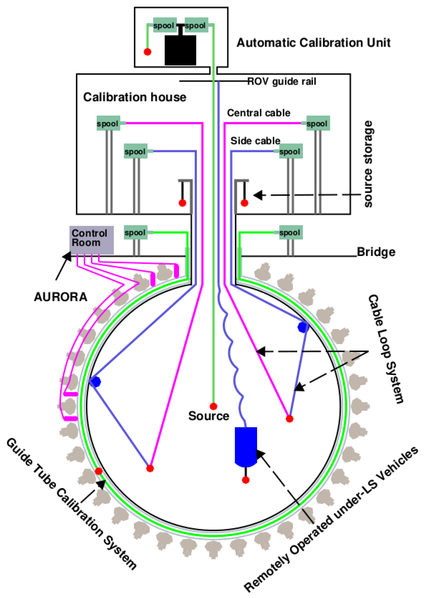
2. Calibration Hardware

The hardware design consists of several independent and low-background subsystems able to deploy the sources in multiple position, and to determine and monitor the detector energy response. The list of radioactive sources that will be considered in these scan systems is reported in Table 1. The background associated with the introduction of calibration subsystems needs to be less than 0.5 Hz to guarantee the low background environment of the detector.
Table 1. List of radioactive sources and processes considered in JUNO calibration.
An overview of the calibration system is shown in Figure 1. The Automatic Calibration Unit (ACU) [4] is designed to scan the central vertical axis of the CD, deploying multiple radioactive sources or a pulsed laser diffuser ball. Two dedicated off-axis systems have been created to monitor the detector non-uniformity and perform two-dimensional scans: the Cable Loop System (CLS) [5], movable on a vertical half-plane, and the Guide Tube system (GT) [6,7], surrounding the outside regions of the CD. To complete the hardware system, a Remotely Operated under-LS Vehicle (ROV) [8] will be deployed to the selected locations to investigate spatial non-uniformity, being capable of deploying a radioactive source in almost the entire LS volume.
Figure 1. Overview of the calibration system: the Automatic Calibration Unit (ACU), two Cable Loop Systems (CLSs), the Guide Tube (GT), and the Remotely Operated Vehicle (ROV).

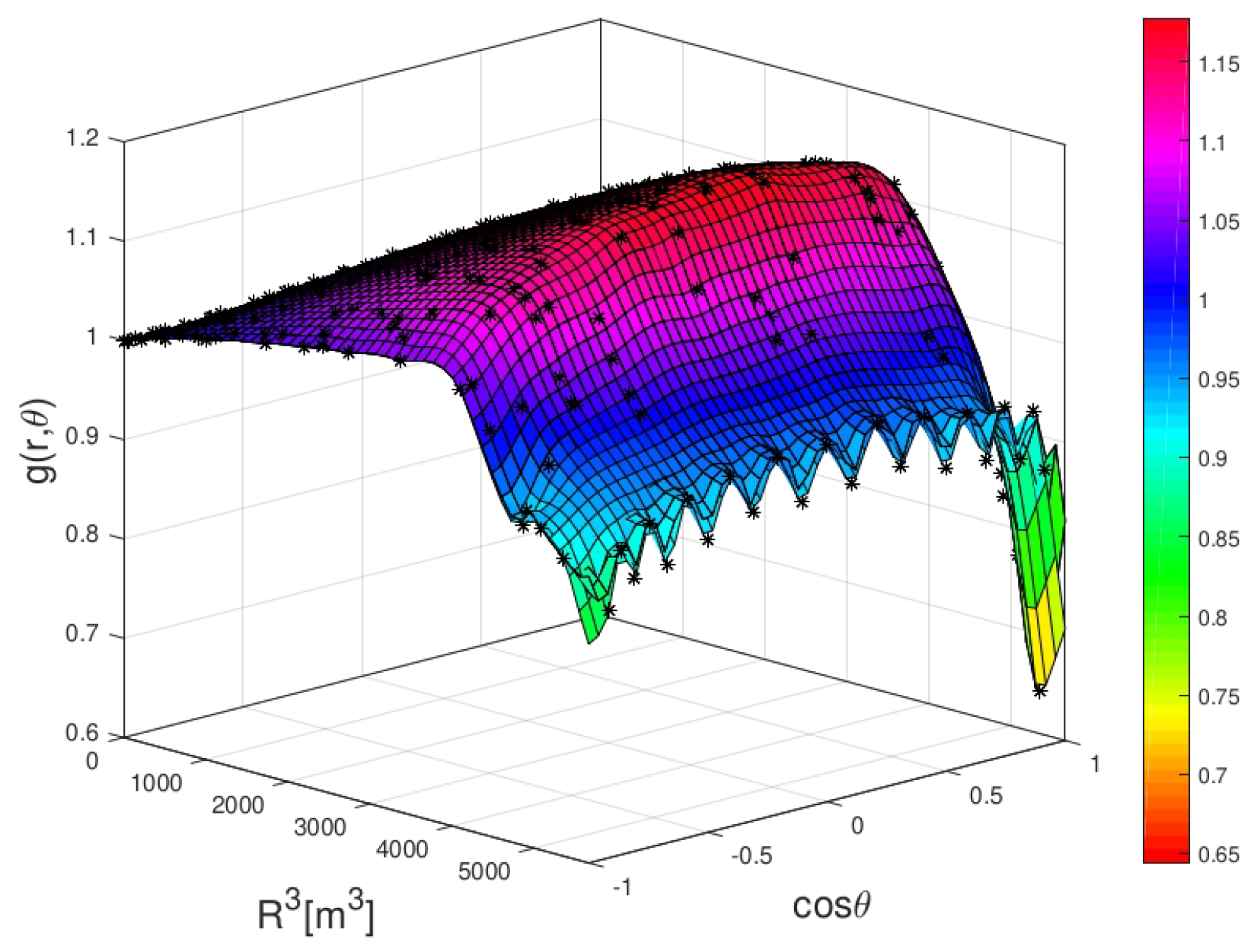
3. Optimization of Energy Resolution

A crucial goal of the calibration campaigns is the optimization of the energy resolution for the IBD positron signals. Given a visible energy E vis of the prompt event, the relative energy resolution for JUNO can be parametrized as:
σ E vis E vis = a E vis 2 + b 2 + c E vis 2
where a 2.7 % is driven by the Poissonian statistics of the number of collected photoelectrons, the constant b term is dominated by the non-uniformity of the detector response, and the c term is mainly related to the dark noise. The b term can be reduced by understanding and correcting the non-uniformity of the energy response, thanks to the calibration campaigns. In other words, the g ( r , θ , φ ) function (Figure 2), which defines the relative light yield in a given position with respect to the light yield at the centre, can indeed be calibrated under realistic conditions. The strategy is based on the deployment of a single γ source to about 250 points in a vertical plane of the CD. This procedure is expected to lead, in the worst case scenario, which includes possible detector imperfections, to a ¯ = a 2 + ( 1.6 b ) 2 + ( c / 1.6 ) 2 = 3.12 % , an effective energy resolution that would be sufficiently good for the 3 σ NMO determination goal [1].
Figure 2. The non–uniformity function g ( r , θ ) in φ = 0 plane as a function of cos θ and R 3 .

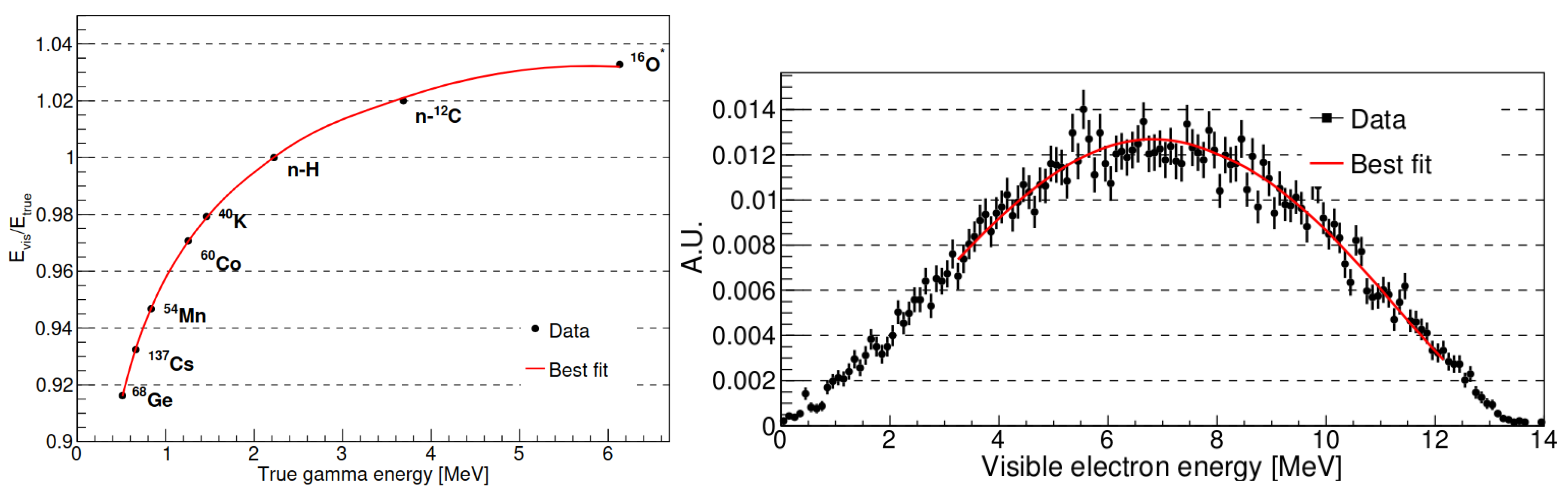
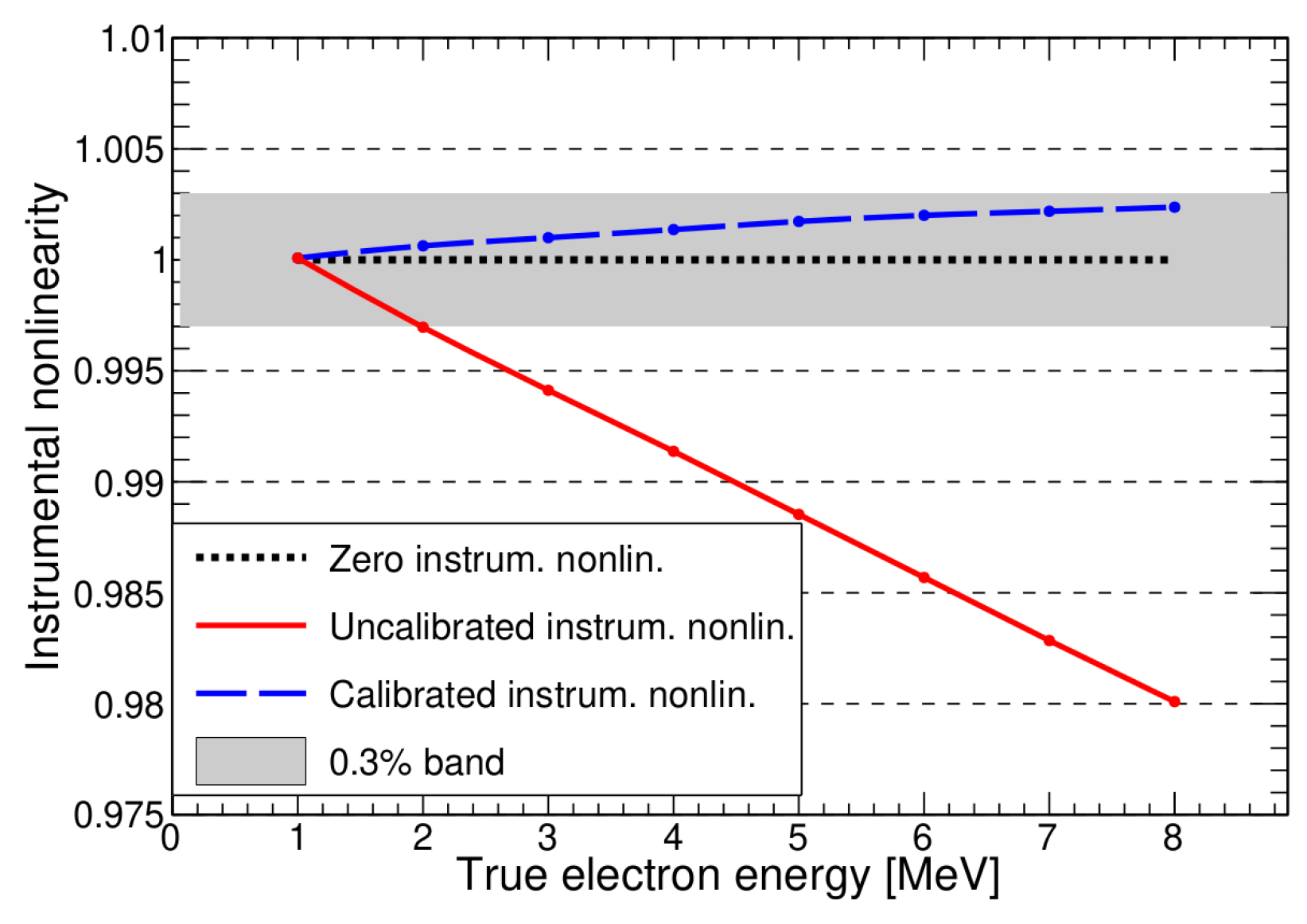
4. Optimization of Non-Linearity

The physics non-linearity, which connects the visible energy and the number of emitted photons, is mainly driven by the quenching effect in the liquid scintillator and by the contribution of Cherenkov photons to the light yield. It can be constrained by combining the information from the multiple γ sources calibration results at the detector centre (left panel of Figure 3), and from the energy fit of the cosmogenic isotope 12 B decay spectrum (right panel of Figure 3). Following this procedure, dedicated simulations show that the residual bias in the reconstructed energy can be kept at 0.2% level.
Figure 3. Physics non-linearity determination: γ sources (left panel) and 12 B spectral (right panel) fit.
The instrumental non-linearity is defined as the ratio of the total measured LPMT charge to the true charge for events uniformly distributed in the detector. It can be calibrated by exploiting the dual calorimetry technique. This is based on the comparison of the response of LPMT and SPMT systems when an uniform illumination is induced by a tunable laser source [9], covering the 1–8 MeV energy range for IBD events. Following a such procedure, the instrumental non-linearity can be controlled at the 0.3% level (Figure 4).
Figure 4. Instrumental non-linearity, defined as the ratio of the total measured LPMT charge to the true charge for events uniformly distributed in the detector.

5. Calibration Program

As discussed previously, a rich and varied calibration strategy is necessary to secure JUNO’s full potential in the determination of the neutrino mass ordering. The designed calibration program is summarized in Table 2. A comprehensive calibration stage, performed at the beginning of the data-taking and sporadically throughout the data-taking, is planned to understand the CD performance at best and to map the energy response non-linearity and non-uniformity, by exploiting γ and neutron sources. The monthly calibrations are meant to monitor the non-uniformity response, by exploiting 241 Am- 13 C and laser sources, both on-axis and off-axis. Weekly calibrations will be conducted to assess the stability of key detector properties, including the light yield of the liquid scintillator, the gains of the PMTs, and the response of the electronics. For this purpose, a neutron source positioned on-axis and a laser at the CD centre will be utilized.
Table 2. The calibration strategy program of the JUNO detector.

Author Contributions

This work is presented on behalf of the JUNO collaboration.

Funding

We are grateful for the ongoing cooperation from the China General Nuclear Power Group. This work was supported by the Chinese Academy of Sciences, the National Key R&D Program of China, the CAS Center for Excellence in Particle Physics, Wuyi University, and the Tsung-Dao Lee Institute of Shanghai Jiao Tong University in China, the Institut National de Physique Nucléaire et de Physique de Particules (IN2P3) in France, the Istituto Nazionale di Fisica Nucleare (INFN) in Italy, the Italian-Chinese collaborative research program MAECI-NSFC, the Fond de la Recherche Scientifique (F.R.S-FNRS) and FWO under the “Excellence of Science–EOS” in Belgium, the Conselho Nacional de Desenvolvimento Científico e Tecnològico in Brazil, the Agencia Nacional de Investigacion y Desarrollo and ANID-Millennium Science Initiative Program-ICN2019_044 in Chile, the Charles University Research Centre and the Ministry of Education, Youth, and Sports in Czech Republic, the Deutsche Forschungsgemeinschaft (DFG), the Helmholtz Association, and the Cluster of Excellence PRISMA+ in Germany, the Joint Institute of Nuclear Research (JINR) and Lomonosov Moscow State University in Russia, the joint Russian Science Foundation (RSF) and National Natural Science Foundation of China (NSFC) research program, the MOST and MOE in Taiwan, the Chulalongkorn University and Suranaree University of Technology in Thailand, University of California at Irvine and the National Science Foundation in USA.

Institutional Review Board Statement

Not applicable.

Data Availability Statement

Not applicable.

Conflicts of Interest

The author declares no conflict of interest.

References

  1. An, F.; An, G.; An, Q.; Antonelli, V.; Baussan, E.; Beacom, J.; Bezrukov, L.; Blyth, S.; Brugnera, R.; Avanzini, M.B.; et al. Neutrino physics with JUNO. J. Phys. G Nucl. Part. Phys. 2016, 43, 030401. [Google Scholar] [CrossRef]
  2. JUNO Collaboration. JUNO physics and detector. Prog. Part. Nucl. Phys. 2022, 123, 103927. [Google Scholar] [CrossRef]
  3. Abusleme, A.; Adam, T.; Ahmad, S.; Ahmed, R.; Aiello, S.; Akram, M.; An, F.; An, G.; An, Q.; Andronico, G.; et al. Calibration Strategy of the JUNO Experiment. J. High Energy Phys. 2021, 2021, 4. [Google Scholar] [CrossRef]
  4. Hui, J.; Liu, H.; Liu, J.; Meng, Y.; Xiao, M.; Xu, D.; Yang, L.; Ye, Z.; Zhang, F.; Zhang, T.; et al. The automatic calibration unit in JUNO. J. Instrum. 2021, 16, T08008. [Google Scholar] [CrossRef]
  5. Zhang, Y.; Hui, J.; Liu, J.; Xiao, M.; Zhang, T.; Zhang, F.; Meng, Y.; Xu, D.; Ye, Z. Cable loop calibration system for Jiangmen Underground Neutrino Observatory. Nucl. Instruments Methods Phys. Res. Sect. A Accel. Spectrometers Detect. Assoc. Equip. 2021, 988, 164867. [Google Scholar] [CrossRef]
  6. Guo, Y.; Zhang, Q.; Zhang, F.; Xiao, M.; Liu, J.; Qu, E. Design of the Guide Tube Calibration System for the JUNO experiment. J. Instrum. 2019, 14, T09005. [Google Scholar] [CrossRef]
  7. Guo, Y.; Zhu, K.; Zhang, Q.; Zhang, F.; Meng, Y.; Liu, J.; Qu, E. Construction and simulation bias study of the guide Tube Calibration System for JUNO. J. Instrum. 2021, 16, T07005. [Google Scholar] [CrossRef]
  8. Feng, K.; Li, D.; Shi, Y.; Qin, K.; Luo, K. A novel remotely operated vehicle as the calibration system in JUNO. J. Instrum. 2018, 13, T12001. [Google Scholar] [CrossRef]
  9. Zhang, Y.; Liu, J.; Xiao, M.; Zhang, F.; Zhang, T. Laser calibration system in JUNO. J. Instrum. 2019, 14, P01009. [Google Scholar] [CrossRef]
Disclaimer/Publisher’s Note: The statements, opinions and data contained in all publications are solely those of the individual author(s) and contributor(s) and not of MDPI and/or the editor(s). MDPI and/or the editor(s) disclaim responsibility for any injury to people or property resulting from any ideas, methods, instructions or products referred to in the content.

Article Metrics

Citations

Article Access Statistics

Multiple requests from the same IP address are counted as one view.