Review

Cu-Based Materials as Photocatalysts for Solar Light Artificial Photosynthesis: Aspects of Engineering Performance, Stability, Selectivity

Laboratory of Physical Chemistry of Materials & Environment, Department of Physics, University of Ioannina, 45110 Ioannina, Greece
*
Author to whom correspondence should be addressed.
Solar 2023, 3(1), 87-112; https://doi.org/10.3390/solar3010008
Submission received: 15 December 2022 / Revised: 15 January 2023 / Accepted: 22 January 2023 / Published: 2 February 2023
(This article belongs to the Special Issue Nanotechnology in Photo-Triggered Processes)

Abstract

:
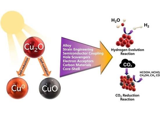
Cu-oxide nanophases (CuO, Cu2O, Cu0) constitute highly potent nanoplatforms for the development of efficient Artificial Photosynthesis catalysts. The highly reducing conduction band edge of the d-electrons in Cu2O dictates its efficiency towards CO2 reduction under sunlight excitation. In the present review, we discuss aspects interlinking the stability under photocorrosion of the (CuO/Cu2O/Cu0) nanophase equilibria, and performance in H2-production/CO2-reduction. Converging literature evidence shows that, because of photocorrosion, single-phase Cu-oxides would not be favorable to be used as a standalone cathodic catalyst/electrode; however, their heterojunctions and the coupling with proper partner materials is an encouraging approach. Distinction between the role of various factors is required to protect the material from photocorrosion, e.g., use of hole scavengers/electron acceptors, band-gap engineering, nano-facet engineering, and selectivity of CO2-reduction pathways, to name a few possible solutions. In this context, herein we discuss examples and synthesis efforts that aim to clarify the role of interfaces, faces, and phase stability under photocatalytic conditions.

Graphical Abstract

1. Introduction

Over the last decades, the negative impact of greenhouse gas emissions on the environment is strongly correlated with air pollution, climate change, and global warming. Carbon dioxide (CO2) is considered one of the main greenhouse gases, thus strategies need to be developed in order to decrease CO2 levels in the atmosphere. The “Artificial Photosynthesis” approach [1] aims to exploit photocatalytic technology, that is the use of solar photons to produce hydrogen (H2) and—ideally—couple it to CO2 reduction towards carbon-based fuels. Economically and environmentally, this is a sustainable, circular economy approach since CO2 reduction can result in useful products such as formic acid (HCOOH), formaldehyde (HCHO), methanol (CH3OH), methane (CH4), and carbon monoxide (CO), to name a few [2].
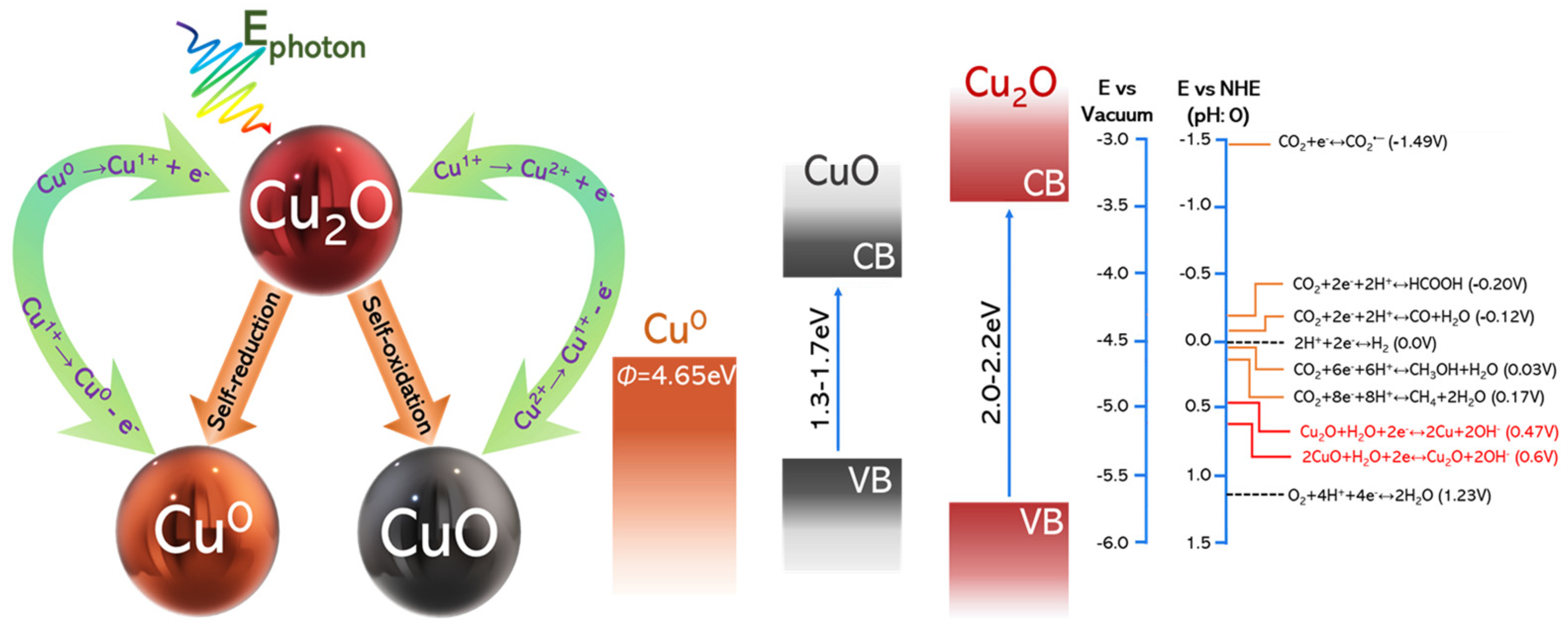
Both photocatalytic H2 evolution from H2O and photocatalytic CO2 reduction reactions (CO2RR) share some common steps, with their difference being on the specific surface reactions of the photogenerated electrons. These steps include, see Figure 1: photon-adsorption by the semiconductor, electron-hole separation and their migration to the semiconductor surface [3], and subsequent incorporation of the electron to a H+, leading towards H2 or to one CO2 radical, leading towards the HCOOH/HCOH/CH3OH/CH4 chain. H2 production can be identified as a less-complex process, compared to the CO2 reduction, the latter involving CO2 adsorption and activation, product formation, and desorption. Thus, CO2 reduction is a multi-proton and multi-electron transfer process and selectivity of the products remains a major challenge (see Figure 1).
The difficulty in activating the inert CO2 molecule lies in its closed-shell electronic configuration, linear geometry, and D∞h symmetry [2]. Thus, it requires a highly negative reduction potential of −1.9 V (vs. NHE at pH 7) to activate CO2 and form the CO2 radical, which the vast majority of semiconductors cannot provide [2].
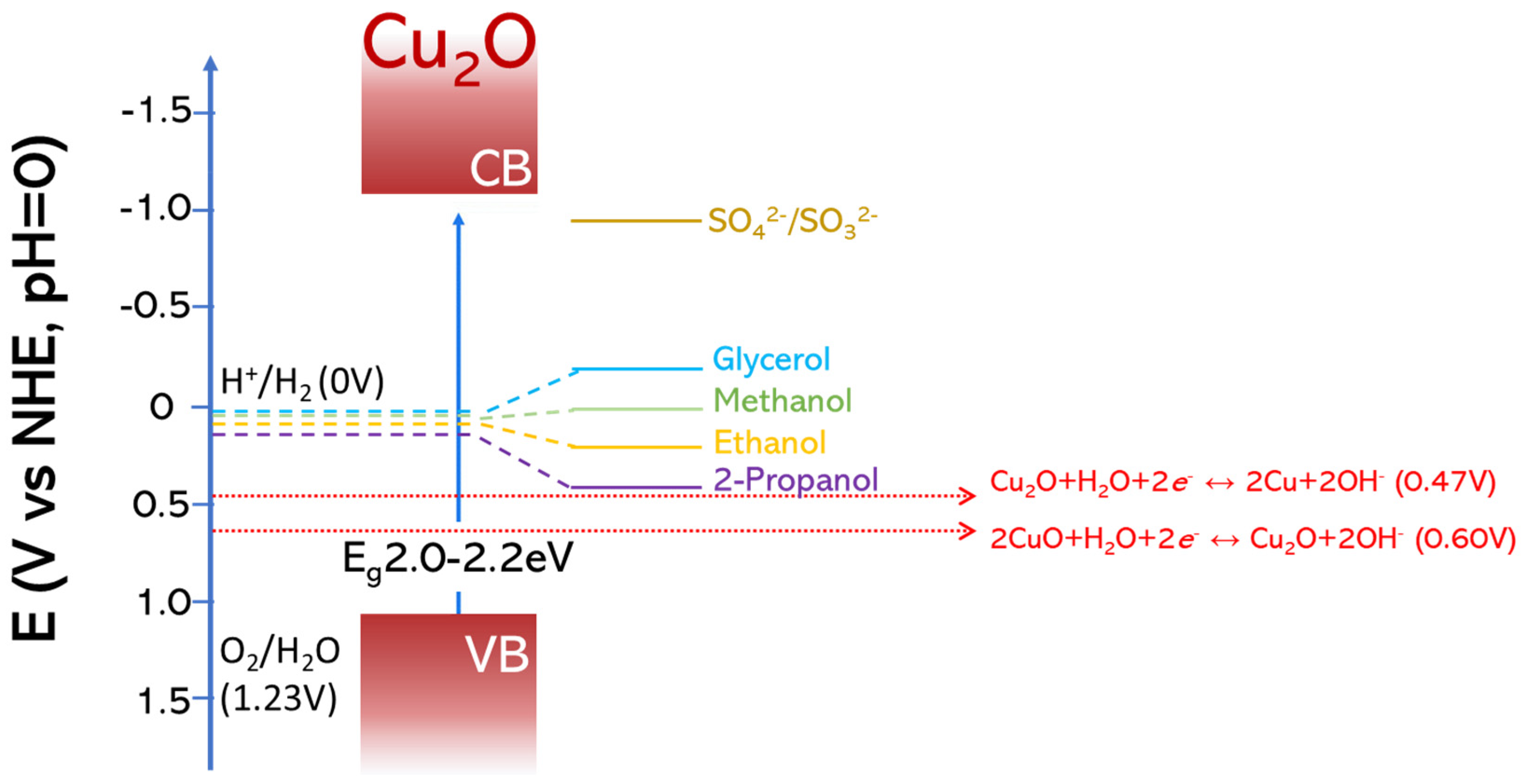
Fujishima and Honda in 1972, [4], paved the way for light-induced water splitting by TiO2 and, since then, numerous studies on photocatalysts were presented, and in particular TiO2 [5,6,7]. Moreover, research interest in photocatalytic and photo-electrochemical applications has increased, prompting successful engineering of various semiconducting photocatalysts [5,8,9,10]. So far, TiO2 remains the most studied photocatalyst, due to its chemical stability, low cost, and availability [11]. However, the large energy gap of TiO2 (3.2 eV) [3] limits its photoactivity exclusively in the ultraviolet radiation range, typically λ < 360 nm, which accounts for 2–5% of the sunlight [12]. Moreover, the conduction band (CB) edge of TiO2 is ECB = −160 mV vs. NHE (pH = 0) or ECB = −50 mV (pH = 7) [3], which disfavors its photoexcited electrons to efficiently achieve reduction of CO2 towards the key intermediate CO2. In this context, p-type Cu2O is considered as highly promising and attractive since it can absorb visible-light photons, Eg in the range 2.0–2.2 eV [13,14,15,16], and mostly due to the highly reducing energy positioning of its conduction-band edge, which is approximately ECB = −1000 mV vs NHE (pH = 0) (see Figure 2) [10].
As an element, Cu has high abundance on Earth’s crust, ease of handling and manufacturing, low cost, and low environmental toxicity. In the family of stable Cu-oxides, Cu2O and CuO are direct-bandgap semiconductors with Eg in the range 2.0–2.2 eV (Cu2O) and 1.3–1.7 eV (CuO) [13,14,15,16], respectively. The variations in Eg values depend mainly on the particle-morphology and nano- vs. bulk-size [17]. The small bandgap energies allow Cu2O and CuO to absorb the majority of solar-photons while their direct-bandgaps endow the two oxides with large photon-absorption coefficients [18,19]. Additionally, it is reported that copper-based catalysts and the different Cu oxidation states can significantly improve the kinetics and thermodynamics of CO2 adsorption, activation, and CO dimerization [20,21]. Li et al. [9] discuss the selectivity of various cocatalysts for the photocatalytic CO2 reduction. In this context, metallic Cu0 is more favorable for the production of hydrocarbons, primarily CH4, while Cu2O favors CH3OH production [2,9].
While CuO is known to be the most stable copper oxide, the stability of Cu2O under photochemical processes, is a matter of concern. The usually reported lack of long-term stability can be attributed to “photocorrosion”, a term referring to the occurrence of lattice-destabilization linked to consumption of the photogenerated carriers, see Figure 2, affecting its overall photo-performance [22]. These events, together with eventual enhanced electron-hole recombination rate in Cu2O and CuO, may be detrimental for Hydrogen-Evolution Reaction photocathodes [13,18,23,24,25]. Pertinent review articles have been published in the literature on the synthesis of Cu-oxides [18,26,27,28], their use as photocatalysts for pollutant degradation, H2-production from water [6,29], and CO2 reduction [10,20,30].
Herein, the aim of this mini-review is to discuss aspects on the photostability of copper oxides, CuO and Cu2O, with focus on some specific, pertinent strategies that have been—so far—reported to improve the photostability. The first part of the review focuses on the photostability problems and the self-decomposition mechanism of CuO and Cu2O. Then, we discuss the different material-engineering approaches such as heterojunctions, core-shell structures, strain engineering, combination with supports. Finally, we provide a targeted overview of some promising Cu-based materials for artificial photosynthesis and discuss the potential strategies employed to enhance the photocatalytic performance. For conciseness, the present review focuses on the reducing process (H2-evolution, CO2 reduction). The oxidizing-side (holes) optimization and mechanisms are out of the scope of the present review.

2. The Problem of Photocorrosion and Some Specific Approaches to Prevent It

From the redox point of view, photocorrosion of Cu2O can be explained, see Figure 2, as being triggered either:
[i]
by the oxidation of Cu1+ to Cu2+, by photogenerated holes. Formally, this tends to convert Cu2O to CuO.
[ii]
by the reduction of Cu1+ to Cu0 by photogenerated or electrochemically provided electrons. Formally, this tends to convert Cu2O to metallic Cu0.
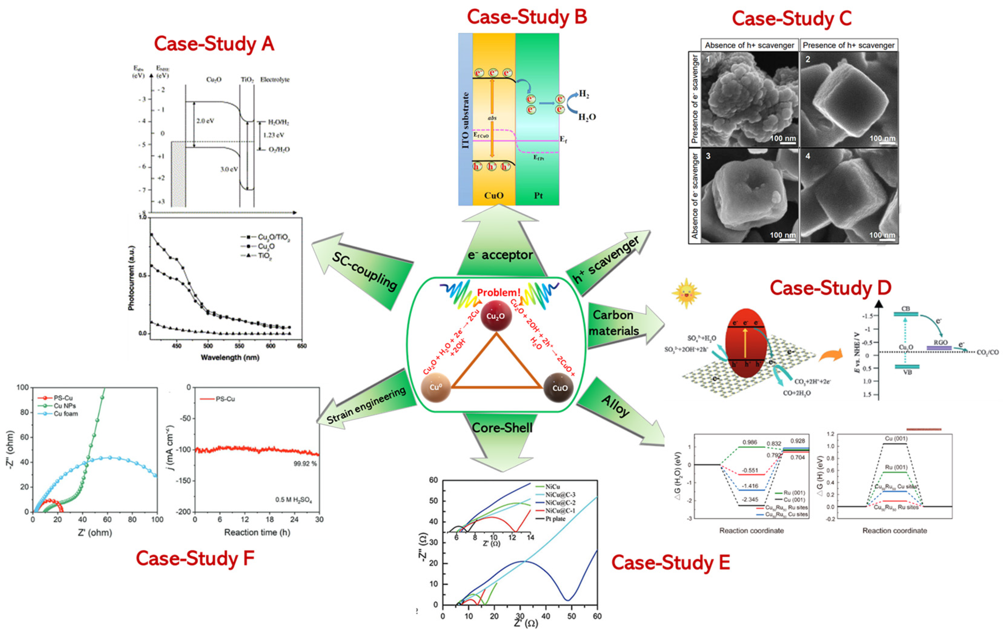
Many nanoengineering approaches aiming to diminish photocorrosion are based on the working hypothesis of the prevention of electron-hole recombination and promoting them out of the Cu-oxide lattice. Hereafter, see Figure 3, we summarize some approaches in this direction.

2.1. Case−Study A: Photocathode-Heterojunctions (e.g., CuxO/TiO2, CuO/BiVO4, CuO/Cu2O)

CuO can be an effective photocatalyst and a photocathode if the self-reduction problem of the Cu2+ sites to Cu1+ is solved via a heterojunction with a n-type semiconductor such as TiO2 [19,34]. This TiO2@CuO core-shell scheme can act as a protective layer, see Figure 3 (Case-Study A). The efficiency of this approach can be influenced by the preparation method. Masudy-Panah et al. [24], via control of the sputtering power, achieved to optimize the TiO2-layer over CuO, and this in turn had a beneficial effect on the photocorrosion stability of CuO-based photocathodes [24]. Under five hours of photocorrosion stability tests, increasing the sputtering power was found to significantly suppresses the formation of Ti3+, which increased the Hydrogen Evolution Reaction (HER) efficiency of the photocathode [24]. The Nyquist-curves recorded by Electrochemical Impedance Spectroscopy (EIS) of thin TiO2-film indicated easier transfer of photoinduced electrons to the electrolyte solution [24]. Xing et al. [26] reported that a protective layer of TiO2 formed by sol-gel method, can be used to protect the CuO photocathode [26]. In this case, they had achieved improved photocurrent density by TiO2@CuO vs. bare CuO photocathode. In [26], the long-term stability was impaired due to a less-homogeneous protective TiO2 layer on the CuO photocathode [26]. Specifically, in the TiO2@CuO core-shell, it was suggested [26] that photoexcited electrons of CuO and TiO2 easily migrate to the CB of TiO2 and the holes from VB of TiO2 transfer to the VB of CuO, while the internal electric field further promotes the separation and transfer of photogenerated carriers in the two components of the Z-heterojunction direction, resulting to a more stable and efficient CuO photocathode [26]. Similarly, the results of [35,36] can be understood as being due to a Z-scheme configuration [37] that is considered to improve electron-hole separation and transfer them to the CB of TiO2 and VB of Cu2O, respectively.
In [23], precise control of Oxygen-rich CuO and Cu-rich CuO regions on the same material was investigated via sputtering on Fluorine Tin Oxide (FTO)-coated glass. It was observed that the stability of CuO electrodes was considerably influenced by the precise local balance of Cu or O elements, with O-rich CuO electrodes to be most stable against photocorrosion [23]. O-rich materials show higher stability against photocorrosion, which might be a result from slower self-reduction of CuO to Cu2O. EIS data showed that, in O-rich CuO electrodes, charge transfer resistance was decreased [23], thus improving interfacial charge transport and photocatalytic performance.
Jeong et al. [38] had fabricated BiVO4/CuO heterojunction electrodes by spin-coating capping layers of BiVO4 on CuO photoelectrodes, in order to prevent self-reduction of CuO to Cu2O. Using X-Ray Photoelectron Spectroscopy (XPS) data, they have observed that CuO photoelectrodes with poor photostability occurred when self-reduction of CuO to Cu2O was occurring, while after repeated BiVO4 deposition cycles, the photocorrosion was suppressed, i.e., a > 76% photostability was reported [38].
In conclusion, heterojunction of Cu-oxide semiconductors with appropriate n-type semiconductors can be a promising strategy to address the issue of Cu2+/Cu1+ self-reduction. Properly accounting for the relative CB and VB positioning, and the ensuing band-bending, is of primary importance in this approach.

2.2. Case−Study B: The Case of e Capture/Acceptor (CuO/Pt and CuO/Pd-Au)

In another approach, to prevent Cu2+ to Cu1+ self-reduction [23], an oxygen-rich CuO film was coated with a noble-metal nanolayer, e.g., Pt or Pd-Au, using sputtering-technology. Improved stability was confirmed by EIS, showing enhanced CuO stability to correlate with decrease of the resistance [23], i.e., photoinduced electrons had higher mobility [23]. Noticeably, in that work, electron-hole generation was improved via the interaction of plasmonic Au with the semiconductor [23]. In a similar approach, adding Pt as an electron accepting catalyst on a CuO was reported in [26], using an electro-deposition method [26] (see Figure 3 Case-Study B). By adding a metal with higher work function than CuO [Φ = 5.3 eV] e.g. such as Pt [Φ = 5.65 eV], the photogenerated electrons can migrate from CuO to the Pt layer, thus be trapped there, until thermodynamic equilibrium is established, forming an inner electric-field between CuO and Pt [39]. The benefit of this approach, is that, by decreasing electron accumulation on CuO, it minimizes the self-reductive corrosion [26].
In an alternative approach, Zhang et al. [40] had anchored single Cu-atoms (Cu-SA) on TiO2 structure by a bottom-up approach, where a metal organic framework (MOF) MIL-125 was used as a substrate to ensure atomic dispersion of atomic cocatalyst and enabled the highest loading amount of approximately 1.5 wt.% Cu. Anchoring Cu on the TiO2 matrix significantly decreased the charge carrier recombination. Loading single Cu-atoms on TiO2 versus pristine TiO2 indicated that the Cu-SA loading might effectively facilitate the transfer of photogenerated electrons from TiO2 to the Cu active sites [40]. This can be attributed to the fact that the redox-potential of Cu2+/Cu1+ (0.16 V vs. NHE) is more positive than CB of TiO2 (−0.1 V vs. NHE). Electrochemical Impedance Spectroscopy Nyquist curves of Cu-SA/TiO2 verify that the Cu-SA species can act as electron acceptors, thus facilitating the interfacial charge separation [40]. The decreased electron-hole recombination was also evident by the photoluminescence data [40], i.e., in Cu-SA TiO2 the recombination of electrons and holes was slower. As a result, long-term stability was reported, i.e., 380 days with minor loss on the catalytic performance [40].
The aforementioned examples, indicate that fast transfer of electrons out from the Cu-oxide matrix, in a non-reversible way, is the key-condition to improve Cu2+ to Cu1+ self-reduction. Thus, the redox positioning of the electron-acceptors vs. the CB of the Cu-atoms in Cu-oxides, is one of the key-parameters to be considered.

2.3. Case−Study C: The Use of Hole Scavengers

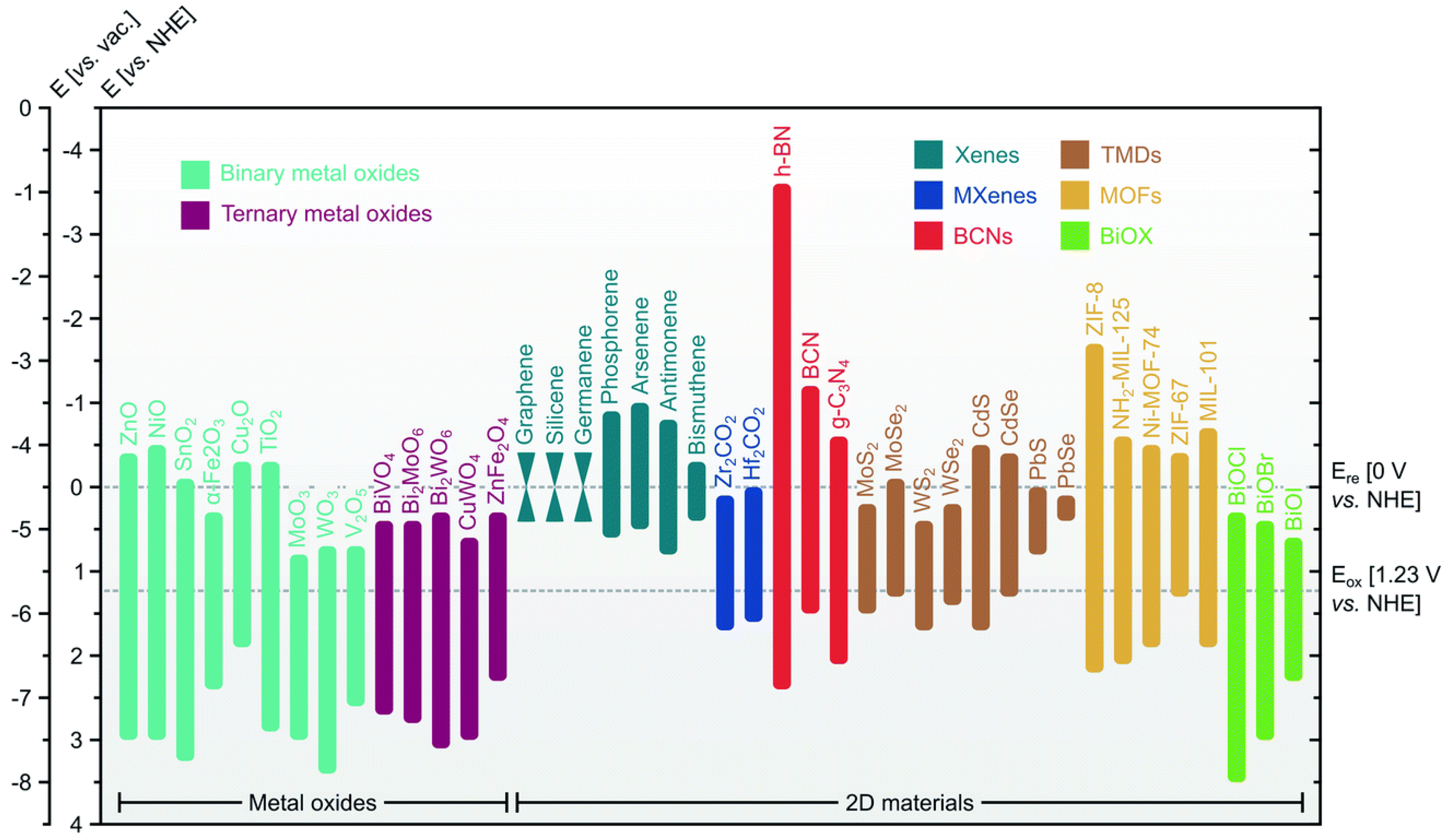
As exemplified in Figure 2, in Cu2O, self-oxidation of Cu1+ to Cu2+ by photogenerated holes, can be a primary photocorrosion source [31]. The highly negative potential CB-edge of Cu2O, typically −1000 mV vs. NHE (pH = 0) [10] boosts the electron transfer to interfacial H+, towards H2 production. Concomitantly, h+ are gradually accumulated and this may promote photocorrosion, oxidation of Cu1+ to Cu2+, since the low level of valence band (VB) prevents h+ to participate in water oxidation. Thus, an efficient hole scavenger would be required to achieve a rapid withdrawal of h+ in order to suppress this Cu2O self-oxidation (see Figure 3 Case-Study C inset). The presence of a h+ scavenger with a suitable oxidizing potential (see Figure 4) facilitates the h+ transfer, thus improving the photostability of Cu2O. In this context, careful selection of a sacrificial hole-scavenger may improve stability by preventing self-photo-oxidation of Cu2O. This in turn, is expected to enhance the overall photocatalytic H2 evolution by Cu2O, permitting an educing potential to be built-up. In this context, Toe et al. [31] demonstrated that among some hole scavengers, e.g., Na2SO3, methanol, and ethanol, Na2SO3 was the most effective in photocatalytic H2 evolution by Cu2O catalysts [31].
Importantly, this study showed that via this approach [31], photocatalytic H2-production from [H2O+scavenger] could be accomplished without any secondary components compared, for example, to the common case of use of alcohols (methanol, isopropanol) as hole scavengers. In [31], Na2SO3 enabled h+ scavenging to oxidize SO32− into SO42−, leaving free e in the conduction band for HER. Importantly, Na2SO3 allowed an effect 12-fold better than ethanol [31], allowing a 15 h production of H2 by the Cu2O/Na2SO3, without any signs of photocorrosion [31]. This approach is interesting since it highlights the possibility to engineer Cu2O without addition of metal or cocatalysts.

2.4. Case−Study D: The Effect of Carbonaceous Materials

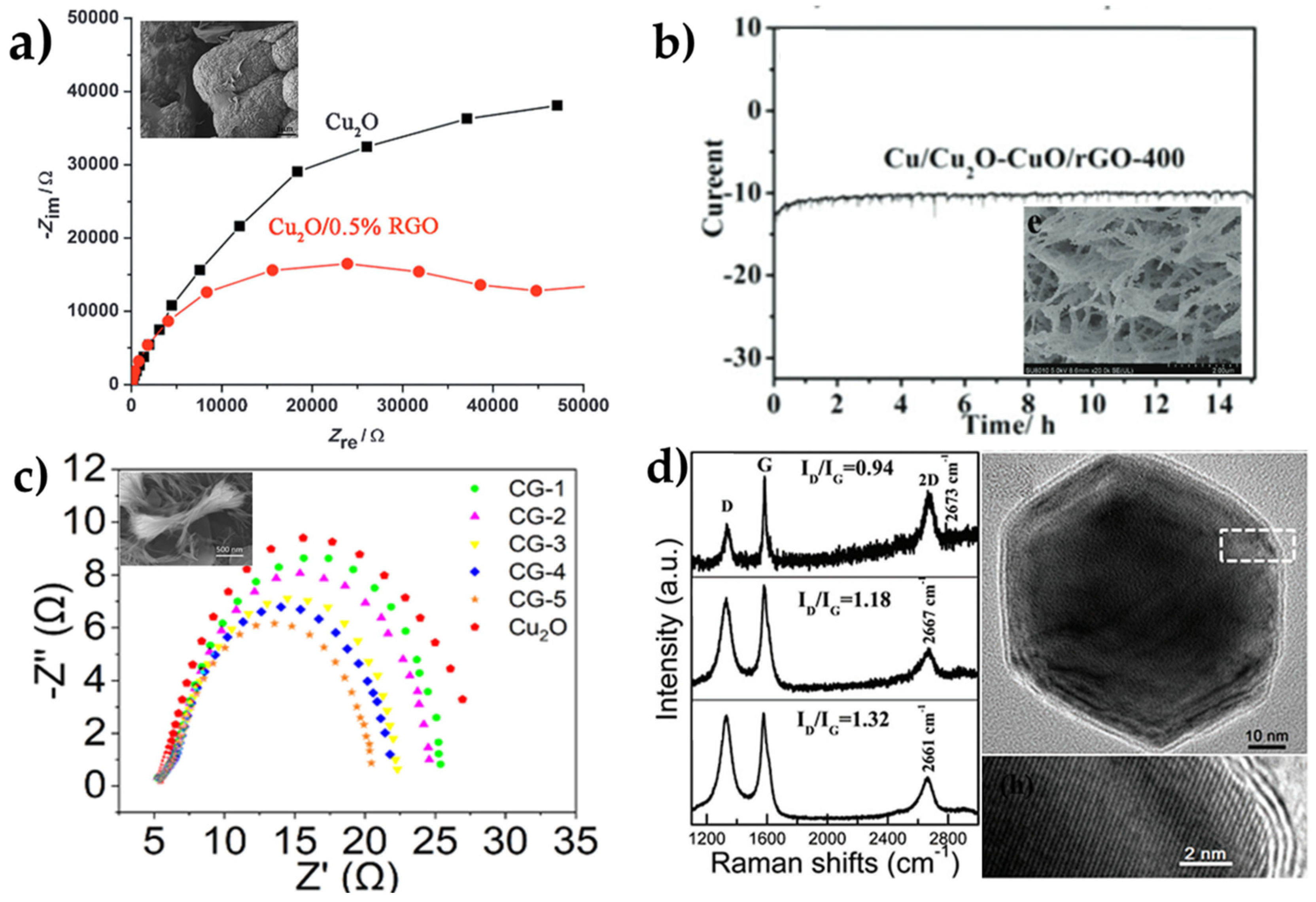
Reduced graphene oxide (rGO) can act as a protecting agent. An et al. [32] have studied the effect of rGO interfaced with different exposed facets of Cu2O with (100) to be better for CO2R than (100) [32]. The proposed mechanism is described in Figure 3 Case-Study D). They measured Cu-leaching using ICP (inductively coupled plasma optical emission spectrometry) and they demonstrated a Cu-atom leaching of ~3% after 3 h of light-irradiated Cu2O/rGO [32]. EIS data showed a smaller resistance indicating better charge-transfer in Cu2O/rGO vs. Cu2O, as can be seen in Figure 5a. In a Mott–Schottky analysis they had a negative slope [32], which indicates p-type semiconductor properties in Cu2O/rGO and an increased donor-density vs. Cu2O.
A different carbonaceous substrate, such as g-C3N4/Vulcan Carbon, was prepared by Hussain et al. [42], protecting the (111) facets of Cu2O, resulting in improved stability of Cu2O nanoparticles. A different approach was given by Sun et al. [43], who developed a heterostructure of Cu2O quantum dots (QDs) supported on a 3D g-C3N4 foam. In this work, the authors suggested that the (111)Cu2O facet, when interfaced with g-C3N4, allowed creation of additional DOS at the Cu2O/g-C3N4 interface [43]. In such heterojunction, the photoexcited electrons are suggested to be transferred from g-C3N4 to Cu2O QDs, thus avoiding Cu2O photocorrosion and enhance photocatalytic activity. Enhanced stability was also evidenced by the reusability of this Cu2O/g-C3N4 heterojunction up to five times [43].
The protective potential of interfacial carbon was also evidenced by Wang et al., who synthesized Cu2O/graphited carbon interfaces, using a polyol-method, to produce Cu2O nano-flowers on graphene [45]. Increased porosity of the catalyst achieved by 90 °C treatment improved the internal charge transfer, as evidenced by EIS Nyquist data and as can be seen in Figure 5c. [45].
Overall, carbon-nanomatrices can act as protecting agents for Cu-oxides. The enhanced electron-storage capacity of graphitized carbon, together with their high chemical resilience are key-beneficial parameters that renders this approach as highly promising towards industrial exploitability.

2.5. Case−Study E: Core-Shell and Alloys

Besides the conventional approach of core-shell structures, in the case of Cu-oxides, one can create core-shell structures by starting from a fully reduced Cu state and result to a reduced metallic-core, with a stable oxidized layer. Yang et al. [18] proposed a two-step method, firstly by electrodeposition of Cu2O on FTO film and a subsequent thermal oxidation (time was the factor that controlled the thickness of the outer layer) in which the outer film was transformed to CuO. The so-formed Cu2O/CuO bilayer was tested for its photostability, and Electrochemical Impedance Spectroscopy data showed very small resistance under illumination, while the Mott–Schottky measurements demonstrated large carrier density and a high flat-band potential, evidencing good conductivity and a high degree of band bending [18]. This approach places the Cu2O/CuO composite as promising photocathode candidate for HER, according to its good stability in alkaline media, high photocurrent, and the ease of method.
A self-supported Cu/Cu2O-CuO/rGO nanowire array [44] showed good stability for more than 15 h in alkaline medium, as can be seen in Figure 5b, in accordance with low resistance evidenced by EIS-loops, which indicates fast charge transfer. This provides evidence that the presence of metallic Cu0 as a hetero-component—not a standalone one—can offer high-speed paths for electron transportation. In addition, the highly reductive rGO shell also provides a conductive network that may promote charge transfer, which are beneficial for the Hydrogen Evolution Reaction process.
A highly efficient and low cost Cu2O-SnO2 core-shell electrocatalyst has been reported in [46] via control of the shell thickness. An optimized 5 nm thick SnO2 shell gave the faradaic efficiency, i.e., >90% of CO2 to CO reduction [46]. These Cu2O-SnO2 electrocatalyst achieved a good stability over 18 h of test at −0.6 V vs. RHE in 0.5 M KHCO3 electrolyte.
A three-dimensional nanoporous Cu-Ru alloy as a Pt-free catalyst for HER, was prepared by Wu et al. [28] using a dealloying process, as shown schematically in Figure 6a,c. They demonstrated that the so-obtained nanoporous Cu53Ru47 exhibits long-term operation stability for more than 24 h in neutral pH (1.0 M PbS) and, after the first 3 h, fully stable at the alkaline pH (1 M KOH), as can be seen in Figure 6b.
Shen et al. started with a fundamental basis, which relies on electronic modification of a graphitic shell [33]. As reported from other groups too, with a graphitic layer to act as a protective shell for the core, this method can improve significantly the durability of the catalyst. Therefore, this group [33] synthesized a nickel-copper alloy (core) encapsuled in graphitic layer (shell) (NiCu@C) via chemical vapor deposition method, using CH4 as a carbon source. This allowed them to obtain a tunable C-thicknesses. In this way, they had obtained three materials: NiCu@C-1 had mostly single-layered (78.4%) C-coating, NiCu@C-2 a well-defined, 2–3 nm thickness, core-shell structure, corresponding to 5–10 graphitic layers, and NiCu@C-3 with an 8–15 nm shell. Raman Spectroscopy, see Figure 5d, shows the three characteristic peaks, D, G, and 2D, that increased upon increase the graphitic shell (C) [32]. Shift in Raman peaks could be related to the modification of electronic structures of graphitic layers arisen from the interaction of carbon shell NiCu core. The stability of the catalyst was evaluated by chronoamperometric measurements, which verify that NiCu@C catalysts show slower decay in both acidic and alkaline pH than in pristine NiCu. From EIS, they demonstrated [32] also that the charge transfer resistance follows the same rule, as the thickness is increasing, the resistance increasing too, which can be explained by slower reaction kinetics and electron transport at the thicker graphitic shells (see Figure 3 Case-Study E- inset).

2.6. Case−Study F: Lattice-Size-Shape-Facets

Lattice-strain engineering can be effective on altering the DOS near the Fermi level, thus regulating adsorption energy of catalysts [27]. This was exemplified by Kang et al. [27], who used plasma spraying (PS) to prepare the coating layer in self-supported Cu electrode with intensive strain. The electrode’s stability was significant for more than 30 h at 100 mA cm−2 (see Figure 3 Case-Study F). EIS data show that their PS-Cu had the lowest resistance of all tested samples, and the stability was best at acid medium and the worst at alkaline medium.
In addition, lattice-strain engineering may improve interaction between catalyst and intermediates [47]. For instance, tensile strain [48] could increase the interatomic distance inside the lattice catalyst, thus decreasing the overlap of d-orbitals, and/or upshift the d-band center and intermediates [49]. In this context, so far, several methodologies have been exploited to generate lattice-strain, such as, introducing interfaces with lattice mismatch [47], creating defects [48], and preparing ultra-thin nanosheets [50].
The different crystallite-facets of metal oxide nanoparticles may affect the activity and stability of photocatalysts for HER and CO2RR, thus controlling preferential-facet growth can be a fruitful strategy. In a commonly applied methodology, the differential affinity of certain surfactants for certain Cu2O-facets may allow control of surface oxidation extent, oxophilicity, hydrophilicity, and their activity to HER [51]. In a refined work, Gao et al. [52] studied Cu2O nanoparticles (NPs) with (100) facets, octahedral Cu2O NPs with exposed (111) and t-Cu2O with both (111) and (100) facets. Studies on these Cu2O NPs showed that the types of interfaced crystal facets exhibited different stabilities and different catalytic activities [53]. Shape of Cu2O particles has been shown to be correlated with stability during the water splitting process [54]. More specifically, when comparing Cu2O cubes with (100) facets, Cu2O octahedra with (111) facets and Cu2O rhombic dodecahedra with (110) facets, it was concluded that—practically—standalone Cu2O, irrespective of the faced exposure, could not be very stable, no matter its facet engineering [53].
From the above-mentioned examples, it may be anticipated that, after finding which facet is best for the catalyst’s activity, we should protect that facet, by an appropriate method, e.g., p-n heterojunctions or coating or by mixing it with carbon materials as graphene.

3. Hydrogen Evolution by Cu-Oxide Based Materials

Both Cu2O and CuO are p-type semiconductors [13,14,15,16] with band gaps 2.0–2.5 eV and 1.3–1.7 eV, respectively, see Figure 2, thus, absorbing a significant proportion of the solar-spectrum. However, their stability issues, when combine with fast e-h+ recombination phenomena, make them rather unfavorable photocatalysts for H2 evolution from H2O [54]. Nonetheless, recent studies demonstrate that we can minimize these disadvantages by coupling copper oxides with other, more stable and suitable semiconductors. Doing so, the electrical and optical properties of Cu2O and CuO are significantly changed by the material they are coupled with [24,28,33].
Hydrogen Evolution Reaction (HER) [55] is considered an extraordinary reaction in electrochemistry for two reasons: firstly, for its simplicity, because it is always a 2e process, no matter the pH [55], and secondly because it is a direct process to produce high-purity H2, considered to be the key fuel for the future. Mechanistically, the basis of HER is described by the reactions in Table 1 [56]. HER in electrochemistry is a 2e process [55], which is divided mainly in two steps: first is the Volmer step (1.i in Table 1) that includes the adsorption of one H-atom on the catalyst surface, by transferring one proton H+ from the acid electrolyte which combines with an electron e transferred from the catalyst surface to form an adsorbed hydrogen atom (H* = H+ + e); second is the Heyrovsky step (Equation (1.ii)) in which this H* combines with one electron e and one H+ to form a H2 molecule, see also Figure 7. In addition, there is possibility to form one H2 molecule through the Tafel step (1.iii) i.e., the combination of two H* [55].
In acidic electrolytes, it has been generally accepted that the differences in reaction rates and activity are closely related to the differences of free-energy of hydrogen-adsorption on different materials [26]. In alkaline media, due to the lack of H+, the reaction must begin from dissociation of H2O molecules, see Volmer–Heyrovsky steps (Equations (2.i) and (2.ii)). In addition, in alkaline media, as in the case of acidic media, there is the possibility to form a H2 molecule through the Tafel step (2.iii), i.e., the combination of two H*. This additional step of proton-generation from H2O in alkaline media introduces an additional energy barrier and affects the whole reaction kinetics and that is the main reason why acid medium is preferred in this reaction. In alkaline environments, there are two approaches to start with: [i] by the single descriptor of hydrogen binding energy [57], or [ii] the bifunctional nature of HER, a good catalyst needs both a beneficial OHad energetics (as it is slower when it has to do with metal; thus, is the rate-limiting step) and beneficial Had energetics [51].
A summary of pertinent Cu-based semiconducting materials is listed in Table 2 (photocatalytic H2 production), Table 3 (electrocatalytic H2 production) and Table 4 (photoelectrocatalytic H2 production). Hereafter, we highlight some engineering aspects related to the control/improvement of hydrogen evolution by such catalysts.
Table 2. Summary of pertinent Cu-based heterojunctions and photocatalytic H2 evolution rates.
Photocatalytic Hydrogen Production
CatalystHole ScavengerIrradiation SourceH2 Evolution RateRef.
Cubic-Cu2OPure H2O (Water Splitting)300 W Xe-LampNot detected[54]
Octahedra-Cu2O>0.4 μmol g−1 h−1
Rhombic Dodecahedra-Cu2O~1.6 μmol g−1 h−1
Cu2O/TiO2 (C-1.5/T-2)30%MeOH (H2O/MeOH)Full-arc Xe Lamp 100 mW cm−211 mmol g−1 h−1[58]
30%MeOH (Seawater/MeOH)5.1 mmol g−1 h−1
CuO (Later Cu2O)-TiO210% Glycerol (H2O/Glycerol)300 W Xe-Lamp336 μmol g−1 h−1[59]
Cu0-TiO2~867 μmol g−1 h−1
Cu2O/TiO210% MeOH (H2O/MeOH)300 W Xe-Lamp70 μmol g−1 h−1[60]
3 wt.% Cu-TiO2~8% MeOH (H2O/MeOH 11:1)125 W Hg-Lamp (325 & 365nm)2.07 mmol g−1 h−1[61]
13.5 wt.% Cu-TiO22.48 mmol g−1 h−1
Electrodeposited Cu2O-WO3Pure H2O (Water Splitting)400 W Hg-Lamp~7 μmol g−1[29]
Cu@Cu2O/ZnO0.75M Na2S and 1.05M Na2SO3300 W Xe-Lamp1.47 mmol g−1 h−1[62]
ZnO/Cu2O-CuO60mM Na2S150 W Xe-Lamp1092.5 μmol g−1 h−1[63]
CuSA-TiO2 (~1.5 wt%)~70% MeOH (H2O/MeOH 1:2)500 W Xe-Lamp101.74 mmol g−1 h−1[40]
0.75% Cu atom-TiO225% MeOH (H2O/MeOH 3:1)100 W Xe-Lamp16.6 mmol g−1 h−1[64]
NDs-Cu2O20% EtOH (H2O/EtOH)300 W Xe-Lamp (100 mW cm−2)1597 μmol g−1 h−1[65]
Visible Light 420–760 nm 77.5 mW cm−2824 μmol g−1 h−1
Cu2O@g-C3N4 (CN5 5wt.%)Pure H2O300 W Xe-Lamp (≥420 nm)795 μmol g−1 h−1[66]

3.1. Photocatalytic Hydrogen Production

3.1.1. Facet Engineering

The shape of Cu2O nanocrystals can affect the photocatalytic H2 production performance [54]. Cu2O nanopowders with different morphologies, i.e., cubes with (100) facets, octahedra with (111) facets, or rhombic dodecahedra with (110) facets, which were evaluated for long-term stability on hydrogen production as well as for overall water-splitting. All materials presented photocorrosion phenomena under irradiation in the form of phase transformation of Cu2O to CuO, verified both by XPS and X-Ray Diffraction (XRD) measurements. Noteworthy, the stability trend was completely different under dark conditions. Moreover, the absence of sacrificial agent during water splitting led to an absence of O2 production, as normally H2 and O2 should have been produced in a 2:1 ratio. Thus, in [54], the photogenerated holes of Cu2O that were supposed to oxidize H2O and produce O2 were consumed in the oxidation of Cu2O to CuO. Furthermore, the best performing material, rhombic dodecahedra Cu2O, was tested for long-term stability where at 48 h the produced H2 was 8-fold less and at 72 h no H2 was detected. To prevent the Cu2O oxidation, the nanocrystals were coated with a TiIrOx layer [54]. This hybrid TiIrOx/Cu2O material had a better photocatalytic performance with a H2:O2 ratio of 2:1, indicating that TiIrOx facilitated the hole transfer, thus preventing photocorrosion of Cu2O, at the same time enabling O2-production from water oxidation.

3.1.2. Coupling with Semiconductors

  • The case of Cu-TiO2
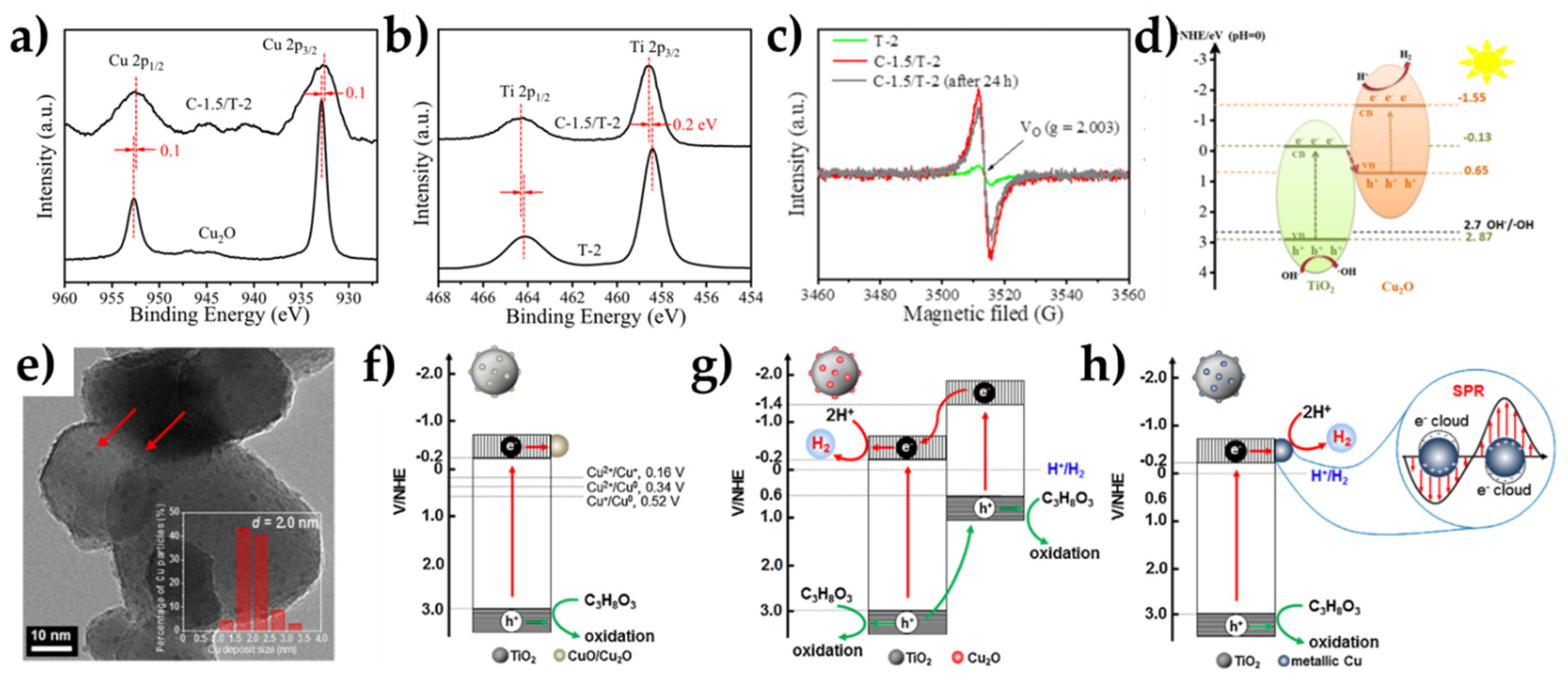
Another strategy is the coupling of CuO or Cu2O with other semiconductors and the establishment heterojunctions or Z-scheme mechanism [37]. Coupling copper oxides with other semiconductors, such as TiO2 or ZnO with lower energy band positions can lead to the formation of Z-Scheme or Type-II electron transfer mechanism between the two materials. Therefore, Cu2O/TiO2 hybrid systems have been widely investigated in the fields of photocatalysis for both H2 evolution [60] and CO2 reduction [67] and degradation of organics [68]. Lv et al. [58] coupled Cu2O nanoparticles onto the surface of TiO2 and showed that, due to the Z-scheme mechanism, carriers with strong oxidation and reduction ability were confined to TiO2, inhibiting the photocorrosion of the Cu2O. XPS and EPR data, see Figure 8a–c, indicated presence of surface lattice defects, oxygen vacancies (OV), which can act both as electron traps and simultaneously enhance the adsorption capability of H+ ions in the hydrogen evolution reaction [58].
Moreover, they notice an upward shift and a downward shift on the XPS spectra of Ti2p and Cu2p, respectively [58], indicating a directional carrier transport from TiO2 to Cu2O (Figure 8a,b). Regarding the photocatalytic activity, their Cu2O/TiO2 composite exhibited high H2 production rates, 11 mmol g−1 h−1 in water and 5.1 mmol g−1 h−1 in seawater [57]. Compared with the pristine Cu2O, yielding 0.5 mmol g−1 h−1 and 0.3 mmol g−1 h−1 in water and seawater, respectively, the Cu2O/TiO2 composite showed a clear improvement. This significant improvement of photocatalytic activity and stability is attributed on the consumption of the highly oxidizing holes of Cu2O from the OV’s of TiO2 and the Z-scheme mechanism [58] (Figure 8d). Generally, stabilizing CuO or Cu2O nanoparticles on TiO2 is a common approach, Tian et al. have prepared a TiO2 photocatalyst loaded with Cu NPs through an ion exchange (IE) process, where they report the co-existence of Cu2+, Cu1+, and Cu0, based on XPS-data. The final composite material gave a purple hue which persisted during the photocatalytic experiments, indicating that copper was at the metallic state [60]. In another study, Jung et al. also used TiO2 as a substrate to deposit small, finely-dispersed CuO NPs (0.5–2.5 nm) [59] (Figure 8e). During H2 generation, they made two observations, [i] there was a color change from dark-grey to deep-violet, attributed to change of the Cu oxidation state, and [ii] there was an initial delay of the hydrogen production. XPS and AES profile at different illumination times show the slow transformation of Cu oxidation states from Cu2+ to Cu1+. The authors [59] suggest that the photogenerated electrons are consumed to reduce CuO to Cu2O instead of reducing H+ and produce H2 (Figure 8f,g). When the reduction of copper has been accomplished, these photogenerated electrons participate in H2 production. In the case of Cu0, as in the cases of noble metal cocatalysts, there is a continuum of states within the TiO2 energy gap where Cu0 attracts the photogenerated electron from TiO2, thus facilitating electron transfer to protons (see Figure 8h).
  • Coupling of Cu with Non-TiO2 Semiconductors
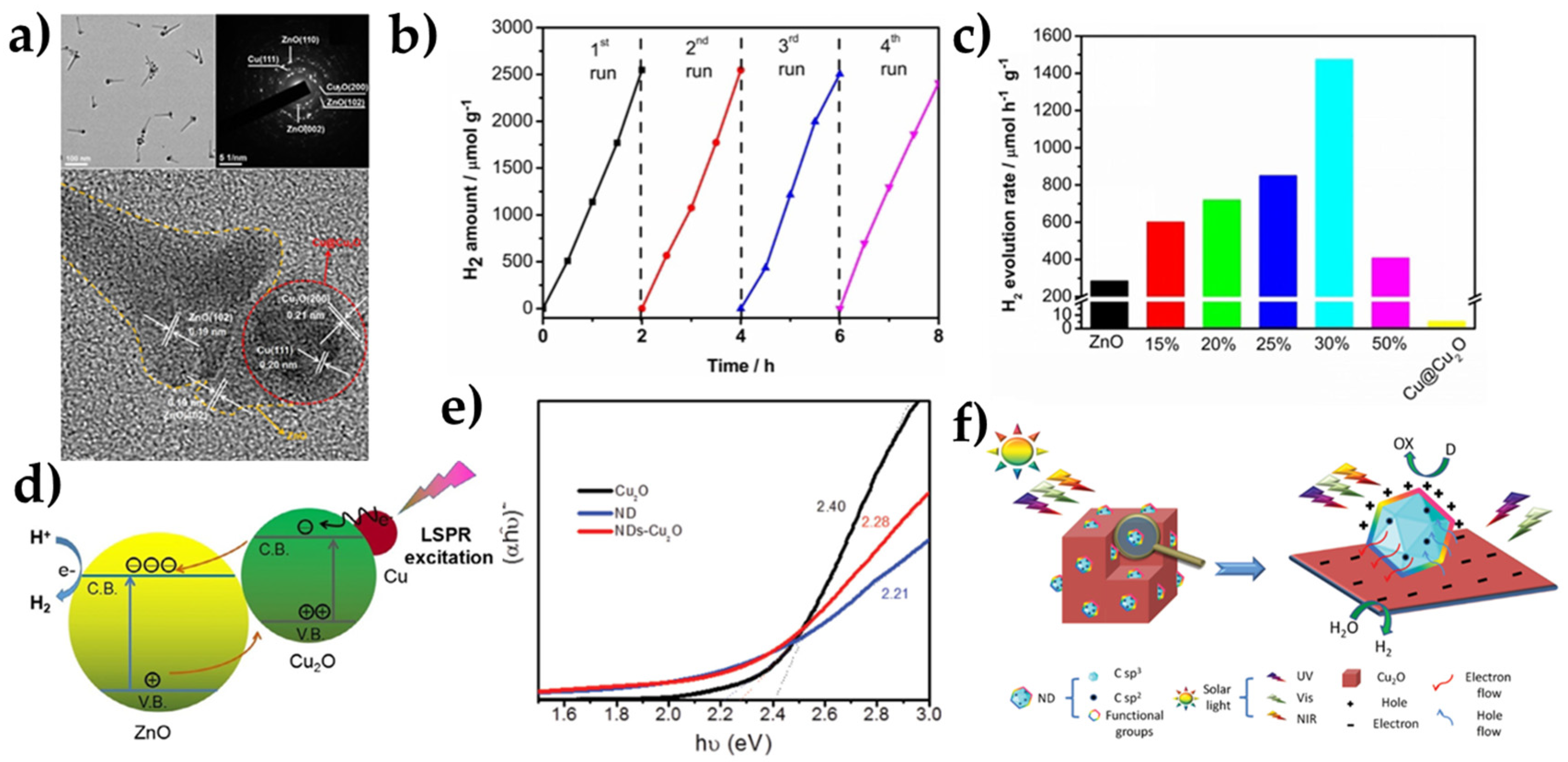
Besides TiO2, other semiconductors, especially n-type, have been also used for the stabilization of Cu NPs. In this context, Hu et al. coupled p-type Cu2O with n-type WO3, forming a p-n heterojunction [29]. Unlike pristine Cu2O, which did not produce H2 during water splitting, Cu2O/WO3 heterojunction facilitated H2 production, due to efficient charge separation. Lou et al. designed a Cu0@Cu2O/ZnO heterostructure in order to stabilize the plasmonic Cu core, by decorating it with Cu2O shell, and finally stabilizing this core-shell structure onto ZnO nanorods [62] (See Figure 9a). This hybrid nanostructure exhibited better stability even after four catalytic cycles (Figure 9b), and superior photocatalytic performance, i.e., 1472μmol g1 h−1 compared with the pristine Cu@Cu2O material which yields 5 μmol g−1 h—1 (See Figure 9c). This improvement on the photocatalytic activity was attributed on the Localized Surface Plasmon Resonance (LSPR) caused by photoexcitation of metallic Cu0 particles [69]. Arguably, the LSPR was suggested to be linked with hot-electron transfer, as evidenced by Photoluminescence (PL) data. Specifically, the PL emission spectra indicated that Cu@Cu2O/ZnO nanocomposites could delay the recombination rate of e-h+ pairs. In the proposed model, see Figure 9d, surface plasmons are photoexcited upon irradiation and the hot electrons occupy the surface plasmon states above the Fermi energy. A fraction of these hot electrons are injected onto the CB of Cu2O, by overcoming the Schottky barrier formed at the Cu2O-Cu0 interface, and finally they leap on the CB of ZnO. This mechanistic path for the electrons is believed to intercept photocorrosion phenomena [62].

3.1.3. Carbon-Based Materials and Core-Shell Structures

Use of carbonaceous materials is another interesting approach towards the stabilization and the improvement of the photocatalytic performance of copper nanocatalysts. Lin et al. has decorated 50 nm Cu2O with small ~3 nm nanodiamonds (NDs), and the optimal loading was found to be 3 wt.% enabling a H2 production rate of 1597 μmol g−1 h−1 with a solar-to-hydrogen efficiency of 0.85%. This nanocomposite exhibited high photocatalytic stability attributed to the narrower band gap, compared with pristine Cu2O, which improves the ability to harvest solar light [65] (See Figure 9e). As for the proposed photocatalytic mechanism, the photoexcited electrons from the NDs surface were injected into the Cu2O and at the same time the photogenerated holes of Cu2O migrated to the NDs (See Figure 9f). The excess of electrons on Cu2O performed the reduction of H2O to H2 and the excess of holes on the NDs oxidized the ethanol. Another material of great interest is graphitic carbon nitride (g-C3N4). Liu et al. synthesized a Cu2O@g-C3N4 core-shell structure onto the Cu2O octahedra with exposed (111) facets. The efficiency of the composite material under visible light irradiation was attributed to the synergistic effect at the interface of Cu2O and g-C3N4, i.e., transfer of the photogenerated electrons of Cu2O to the g-C3N4 shell. In contrast, UV irradiation on the Cu2O crystals had a negative effect, and this was attributed to a mechanism where OV in Cu2O act as electron traps, leading to the reduction of Cu2O to Cu0 exhibiting lower photocatalytic activity [66].

3.1.4. The Case of Cu-Single Atoms

Lastly, single-atom catalysts (SACs) are gaining more and more interest owing to their ability in maximizing reaction active sites [70]. These isolated metal atoms anchored in the surface of photocatalysts may offer more reaction active sites, but their stability and tendency to aggregate during photocatalysis is still an issue to address. Very recently, Lee et al. [64] designed atomically-dispersed Cu on TiO2 by incorporating site-specific single atoms of Cu. Interestingly, it was shown that photogenerated electrons can be transferred from the CB of TiO2 to the d-orbitals of the isolated Cu2+ atoms. These trapped electrons induced a polarization field resulting in lattice distortion of TiO2, that was suggested to be linked with the enhanced photocatalytic H2 activity. This phenomenon was reversible when the material was exposed to O2 without irradiation. They also report a change of color during photocatalysis, in accordance with other studies on TiO2-based nanocatalysts [58,59]. In another very recent study, Zhang et al. managed to deposit higher amounts of CuSA (>1 wt%) on TiO2, at this point we should note that normally the loading percentages of SACs is near 0.1–0.3 wt% [40]. Their optimized material exhibited the impressive H2 evolution rate of 101.7 mmol g−1 h−1, which in their case was higher than PtSA-TiO2 (95.3 mmol g−1 h−1). This impressive photocatalytic performance is attributed to the larger amount of Cu SACs as well as to the high dispersion onto the TiO2 surface. Regarding the photocatalytic mechanism, efficient electron transfer is attributed to the reversible redox process between Cu2+ and Cu1+ atoms. These findings are supported by Electron Paramagnetic Resonance (EPR) data, showing a strong Cu2+ EPR signal before irradiation, which during irradiation was converted to Cu+, which was re-oxidized to Cu2+ after exposure to air O2 [40]. This in situ self-healing process enables CuSA-TiO2 to achieve these remarkable H2 production rates. Furthermore, long-term H2 evolution experiments, i.e., 380 days later, showed no loss of the photocatalytic performance [40].

3.2. Electrocatalytic Hydrogen Production

Electrochemistry permits quantitative comparisons of activity stability, while photo-electrochemistry permits more advanced parameters to be monitored, i.e., photocurrent density, photo-response, photostability and photocorrosion. In brief, the tools used can be [56]:
[i]
exploring the intrinsic activity of catalysts by measuring the capacitance of double layer Cdl to detect the electrochemical active surface area (ESCA) [71],
[ii]
overpotential needs to be the lowest possible, at 10 mA/cm2 [72],
[iii]
the Tafel slope shows the rate of adsorption–desorption kinetics, where the electrochemical desorption step is rate-determining according to the Volmer–Heyrovsky mechanism [73].
[iv]
through EIS measurements the charge transfer resistance can easily be found [56].
[v]
Mott–Schottky plots can provide information about flat band potential and the populations of donors and acceptors [74].
The double-layer capacitance which can be determined by cyclic voltammetry measurements, the electrochemically active surface area, current density [56], and the faradaic efficiency of the sample [75]. Linear Sweep Voltammetry (LSV) provides a measure of overpotentials necessary to achieve j = 10 mA/cm2, and after 2 h to check the stability, or even a long-term stability test which can last up to 24 h [76].
In Table 3, we summarize pertinent values for these electrochemical parameters for selected Cu-oxide catalysts.
In Table 3, pertinent literature works are presented. In all cases, we mention works where they did not use noble metals as co-catalysts, but use only Cu-based electrocatalysts. Some of them had merged the electrolytes with graphene as a core-shell structure in order to protect them from corrosion [77], while others [44,78] used carbon nanotubes with Cu or Cu/Cu2O/CuO structures merged in reduced graphene oxide. An important contribution is a strain-activated copper catalyst [27], operating under a wide pH range. In [27] the current density achieved was1.987 A cm−2 at −1.2 V vs. RHE, which is 2.85 times vs. a reference Pt foil.
Moreover, a three-dimensional nanoporous Cu-Ru alloy as an outstanding Pt-free catalyst for HER has been prepared by a dealloying process by Wu et al. [28]. This catalyst had a good activity with a very low overpotential and very low Tafel slopes in alkaline and neutral environments. By alloying those two metals, Cu and Ru, the incorporation of Ru atoms in the Cu matrix enhanced the strength of the Cu-H interaction, while it weakened the Ru-H interaction, but improved the overall activity [27]. The Electrochemical impedance spectroscopy measurements of np-Cu53Ru47 further confirmed that the incorporation of Ru atoms into the Cu matrix brings about small internal resistance and fast charge-transfer behavior. The same group, [27], demonstrated with Density Functional Theory (DFT) that the incorporation of Ru atoms into the Cu matrix could effectively optimize the d-electron domination of Cu and Ru atoms and decrease the energy barrier and improving the HER activity.
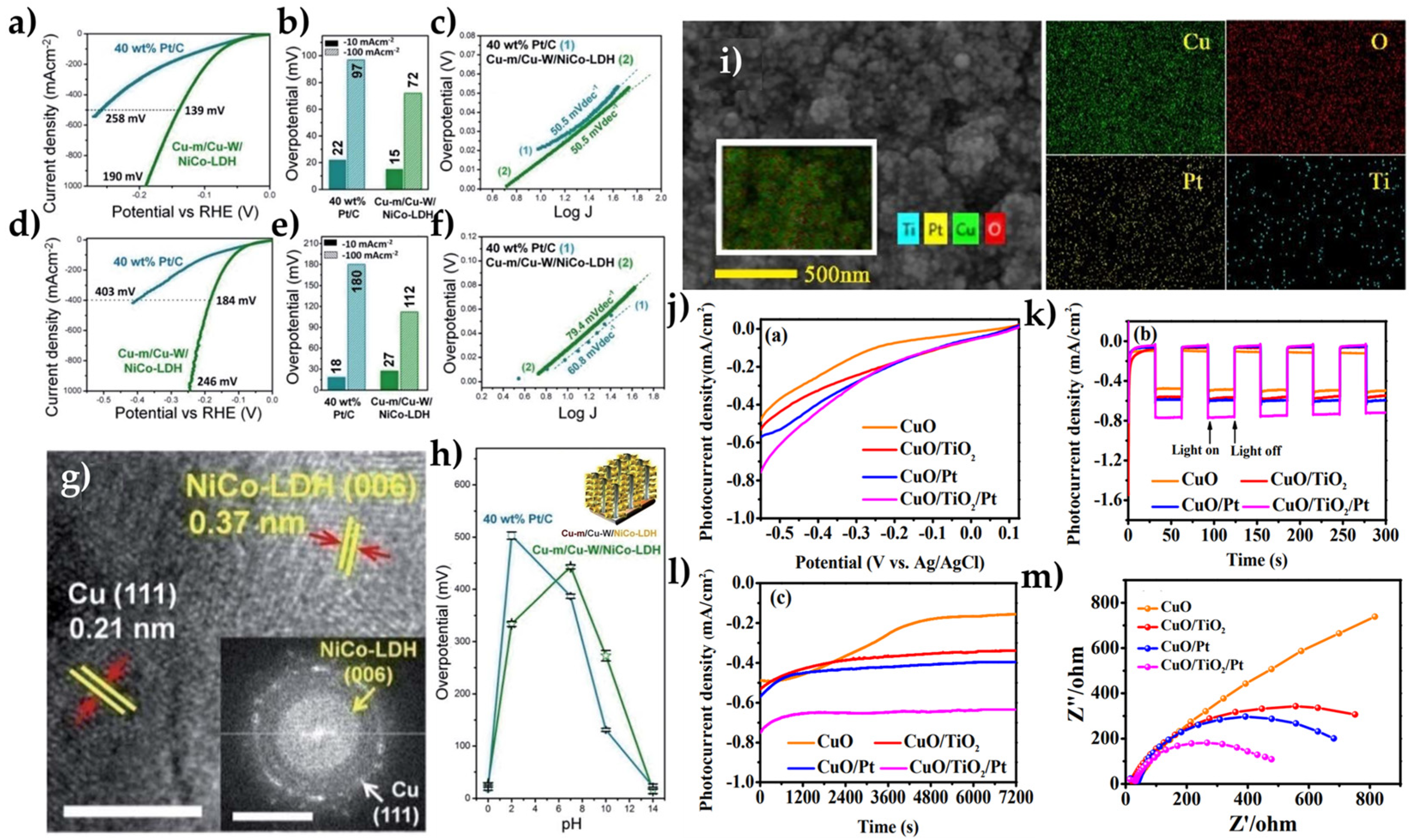
Another approach [79] presented a complex heterostructure of NiCo layered double hydroxide wrapped around Cu nanowires grown on top of commercially available Cu mesh (Cu-m). This Cu-m/Cu-W/NiCo-LDH material outperformed the benchmark 40 wt% Pt/C at a wide pH range [79]. As shown in Figure 10a,b, the required overpotential was smaller for alkaline medium than 40%Pt/C, confirmed by the Tafel plots at Figure 10c. While in acidic environment, as shown in Figure 10d,e, the Cu-m/Cu-W/NiCo-LDH had increased overpotential versus 40%Pt/C at −10 mA cm−2, while the Tafel slope in Figure 10f shows a decreased value for Cu-m/Cu-W/NiCo-LDH. Figure 10h shows the required potential across the pH range to reach −10 mA cm−2 for Cu-m/Cu-W/NiCo-LDH versus 40 wt% Pt/C. In Figure 10g, high-resolution transmission electron microscopy (HRTEM) shows the (111) exposed facets of Cu-m and Cu-Ws, and the latter’s growth direction is along (111).

3.3. Photoelectrochemical Hydrogen Evolution Reaction

Photoelectrochemical cells (PEC) are widely considered potent for solar water splitting devices [80] because they combine solar energy collection with water electrolysis and because they spatially separate two half-cell reactions, HER and OER. For a PEC cell, the process depends on three steps [55]: (i) light absorption by a semiconductor material, (ii) electron-hole pair generation, and, as a result, (iii) photoinduced electrons (or holes) are driven, by space-charge field, to the semiconductor/solution interface where they reduce or oxidize water.
Usually, a PEC cell has a n-type semiconductors, such as TiO2, ZnO, BiVO4, WO3, Fe2O3 [4,81,82,83] whose valence band edges are more positive than the potential of the H2O/O2 redox couple, that makes them ideal for OER photoanodes. On the other hand, p-type semiconductors such as p-CdS, p-WSe, p-InP and p-type Copper Oxides [25,84,85], whose conduction band edge is more negative than the H2O/H2 potential, are ideal for HER photocathodes (see Figure 11). In Table 4, we selected some interesting works from several groups, who have presented durable and stable photocathodes for a PEC cell. In addition, very important for these catalysts is to have good light response and photocurrent to benchmark their photocatalytic activity.
In order to explore the photocorrosion of CuO, Xing et al. [26] had tested heterojunctions CuO: CuO/TiO2, CuO/Pt, and CuO/TiO2/Pt as photocathodes. Under increased protection of the photocathodes, allowed increase of the photocurrent density at −0.55 V, as shown in Figure 10j. The composite of CuO/TiO2/Pt had the highest photocurrent density. In addition, according to the Figure 10k, CuO/TiO2/Pt seems to have a very good photo-response, at −0.55 V vs. Ag/AgCl applied under 30 s light on/off cycles for more than 300 s. This electrode was stable against photocorrosion in 1 M NaOH electrolyte at −0.55 V vs. Ag/AgCl under simulated sunlight illumination for 2 h, Figure 10l. The EIS Nyquist plot, shown in Figure 10m, reveals that the CuO/TiO2/Pt has decreased resistance in charge transfer phenomena, which indicates easier transfer of photoinduced electrons to the electrolyte solution.
Table 4. Pertinent Cu-based materials for PhotoElectrochemical Hydrogen Evolution Reaction based on their catalytic activity.
Photoelectrochemical Hydrogen Production
CatalystEnvironmentLight SourceJ @ Applied Potential Ref.
CuO/TiO21 M KOH500 W Xe-Lamp−0.54 mA/cm2 @ −0.55 V vs. Ag/AgCl[26]
CuO/Pt1 M KOH−0.57 mA/cm2 @ −0.55 V vs. Ag/AgCl
CuO/TiO2/Pt1 M KOH−0.75 mA/cm2 @ −0.55 V vs. Ag/AgCl
Cu2O/CuO
Bilayered composite
0.5 M Na2SO4 + 1 M KOH300 W Xe-Lamp (1000 mW m−2)−3.15 mA/cm2 @ 0.40V vs. RHE[18]
Cu2O/Ga2O3/TiO2/Rux0.5 M Na2SO4 + 0.1 M phosphate solution 300 W Xe-Lamp (1000 mW m−2)−10 mA/cm2 @ 0V vs. RHE[87]
3D CuO 150 W solar simulator (1000 mW m−2)−3.15 mA/cm2 @ 0.42V vs. RHE[88]
CuO/thin film0.1 M Na2SO4Sunlight (1000 mW m−2)−3.1 mA/cm2 @ 0V vs. RHE [23]
Au-Pd decorated CuO thin film0.1 M Na2SO4Sunlight (1000 mW m−2)−3.88 mA/cm2 @ 0V vs. RHE
CuSA-TiO20.2 M Na2SO4150 W Xe-Lamp−10 mA/cm2 @ −0.72V vs. NHE[40]
As general conclusion, photocorrosion must be scrutinized as another important phenomenon in PEC for solar hydrogen production. This aspect is considered using molecular components such as linkers, non-oxide material modifiers, or catalysts. The most common method, as mentioned in Table 4, is by using TiO2 as a matrix where CuO, Cu2O can be protected by photocorrosion through the Z-scheme mechanism. In the case of single-Cu atoms, there is a different approach, where Cu(II) transforms reversibly to Cu(I) during photoelectrocatalysis as described before.

4. CO2 Reduction by Cu-Based Materials

From an economic and environmental point of view, (electro)photocatalytic CO2 reduction is a forward-looking realm in catalytic technology. Inspired by natural-photosynthesis, scientists are trying to realize “Artificial-Photosynthesis”, convert CO2 into useful and high value chemical fuels, using the highly abundant solar energy (see Figure 1). Inoue together with Fujishima and Honda pioneered the idea of the feasibility of catalytic conversion of CO2 to C1-fuels using semiconductors [4,89]. Since then, many efforts were made to improve the overall performance and tune the selectivity towards a specific product [9]. In this context, Cu-oxides and metal-Cu particles emerge among the most promising photocatalysts thanks to good electron transfer properties and loosely bound d-electrons, thus having great potential for facilitating CO2 photoreduction [20]. Herein, we focus on Cu-based semiconductors coupled with other oxide semiconductors, carbon-based materials or plain copper catalysts with facet modifications and discuss stability issues and product selectivity (see Table 5).

4.1. Photocatalytic CO2 Reduction

4.1.1. Facet Dependency of CO2 Reduction

As in the case of photocatalytic H2 evolution, see Section 3.1.1, facet engineering of Cu oxides shows high promise towards increased performance in photocatalytic CO2 reduction [10]. Recently, Wu et al. reported the photocatalytic reduction of CO2 on facet specific active sites of Cu2O [90]. They demonstrated that the (110) facet of a single Cu2O particle was the photoactive site towards CO2 reduction to CH3OH, while the (100) facet remained inert [90]. This observation can be attributed to electron-density difference on Cu active sites on the (110) facet and a shift from Cu(I) to Cu(II) due to CO2 and H2O adsorption [90]. In this way, during CO2 reduction, the Cu2O catalyst manages to oxidize H2O accompanied with a lattice expansion due to the CO2 adsorption. This process showed a selectivity towards methanol yielding 1.2 mol CH3OH g−1 h−1 and reaching an internal quantum yield of ~72% [90].

4.1.2. Coupling with Semiconductors

  • The Case of Cu-TiO2
Cu2O coupling with TiO2 has been explored as an efficient strategy to enhance photocatalytic performance. More specifically, Aguirre et al. synthesized a p-n Cu2O/TiO2 heterojunction, where the Z-scheme mechanism of electron transfer [37] enhances the stability of Cu2O [67] (see Figure 12a,b). The energetics of this example are educative. TiO2 alone exhibits very low CO2-to-fuel-conversion efficiency under UV excitation, while Cu2O possesses a more favorable ECB = −1.4 eV vs. NHE (pH = 7) [103]; however, it suffers from photostability issues [13]. In the p-n Cu2O/TiO2 scheme, Cu(0) was not observed during photocatalytic experiments. In contrast, compared with pure Cu2O, an increase of Cu(II)/Cu(I) ratio [67] was observed (see Figure 12c). Liu et al. had prepared a Cu/TiO2 catalyst tailoring Cu valence and oxygen vacancies of the composite [93]. By thermal treatment under reducing atmosphere (H2 and He) they exhibit the formation of defect sites, i.e., OV’s and Ti3+ centers which affected the CO production. Moreover, during the reduction process through calcination, there was a change on the Cu oxidation states from Cu2+ to Cu1+ or Cu0. These Cu1+ species can effectively trap electrons due to the more positive reduction potential of Cu+/Cu0 (+0.52eV) couple vs. that of Cu2+/Cu0 (+0.34 eV) [104]. The Cu+/Cu0 couple can play a dual role where Cu1+ species trap electrons, and Cu0 species can effectively trap holes [93]. Xiong et al. had used TiO2 crystals as a matrix to deposit Pt and Cu2O NPs where Cu2O promoted CH4 production but suppressed H2 evolution [92]. In that case, Pt favored the activation of H2O while Cu2O performed the CO2 reduction. After the photocatalytic reaction, most of the Cu2O phase was reduced to Cu0, indicating that Pt promotes e-transfer to Cu2O during photocatalysis. Afterwards, the so-formed metallic Cu0 enhanced the selective CH4 production, a well-known property of metallic Cu [92].
  • The Case of Cu Coupling with Non-TiO2 Semiconductors
As we have already stated, p-n junctions of Cu2O with appropriate n-type metal-oxides can exhibit better charge separation and enhanced photocatalytic activity for CO2 reduction. ZnO as an n-type semiconductor possesses a large energy gap of 3.2–3.3 eV with high electron mobility and low dielectric constant, e.g., compared to TiO2. Bae et al. [95] used ZnO-Cu2O nanohybrids to reduce CO2 to CH4 in an CO2-saturated aqueous medium without use of hole scavenger [95]. Once again, the Z-scheme was the proposed mechanism and when compared to TiO2(P25)-Cu2O, the ZnO-Cu2O exhibited superior reaction activity and selectivity. Another work [96] reported the synthesis of a CuO-NaTaO3 hybrid with the ability to reduce CO2 to CH3OH with a maximum yield of 1302 μmol CH3OH g−1 h−1. As expected, smaller, and more uniform distribution of CuO NPs exhibited better catalytic performance. Noteworthy, in that work [96], CuO was suggested to be the CO2 reduction site, while NaTaO3 was the hole-scavenging site, and oxidized isopropanol to acetone. XPS analysis indicated the presence of Cu2+ species only, i.e., by CuO; however, a post catalytic analysis was missing.

4.1.3. Carbon-Based Materials and Core-Shell Cu-Oxide Structures

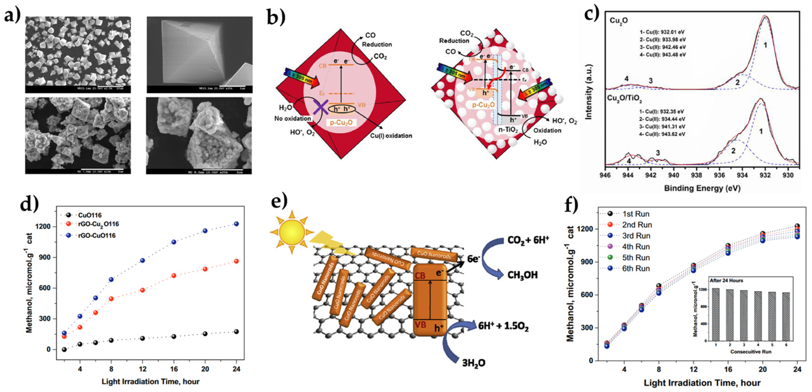
Incorporating copper oxide in carbon-based materials such as rGO, g-C3N4, or carbon coating, is a widely used strategy in photocatalytic CO2 reduction. Graphene-based materials are gaining attention, due to their characteristics, high specific area and adsorption capacity, as well as excellent electron mobility and chemical stability [105]. Gusain et al. prepared rGO-CuO/Cu2O nanohybrids and used them for photocatalytic conversion of CO2 to CH3OH [100] (see Figure 12d). rGO interfaced with semiconducting materials can serve as an electron bridge and enhance the electron transfer process, a step crucial for the photocatalytic reactions [106]. In that work [106], it was suggested that the photogenerated electrons of CuO can be efficiently transferred to rGO, inhibiting in this way the electron hole recombination (see Figure 12e). Moreover, the high surface area and the defects of rGO can enhance CO2 adsorption [100]. Noticeably, CuO (Cu2+) nanorods grafted on rGO exhibited better photocatalytic activity than a rGO/Cu2O (Cu1+) nanocomposite. Stability experiments indicated that after six catalytic runs, there were no significant changes in the morphological and chemical characteristics of the nanocomposite [100] (see Figure 12f). In another work, Chang et al. fabricated Cu2O/gCN nanocomposites with different Cu2O morphologies [101]. The main gaseous product of CO2 reduction was CO with c-Cu2O/gCN being the best performing photocatalyst. The high activity of c-Cu2O/gCN was suggested to be linked with the improved CO2 adsorption as well as the formation of CuO [101].

5. Conclusions

Herein, we discuss cases of pertinent Cu-based materials, that under appropriate coupling and engineering (facet and strain) aimed to resolve stability problems (corrosion and photocorrosion). There are many factors to be taken into consideration, such as the catalytic environment, the wavelength and intensity of irradiation source, and primarily the Cu oxidation state, which is proven to be a crucial factor determining the catalytic performance. Fundamental steps towards the stabilization and durability of Cu-based materials include the selection of a proper semiconductor coupling, suitable sacrificial agents, surface protection through core-shell structures and stabilization on defect sites of the substrate matrix. Z-scheme mechanisms could lead to the stabilization of Cu2O through enhanced charge-separation of the photogenerated carriers. In addition, the proper selection of Cu oxidation states can tune the selectivity towards specific CO2 reduction products. It is important to mention that the vast majority of Cu-based nanocatalysts discussed herein were noble-metal free. To conclude, the reviewed works indicate that the Cu-oxide nanophases constitute highly potent nanoplatforms for development of efficient artificial photosynthesis catalysts. There is converging evidence that—probably—pure Cu-phases would be difficult to be used as standalone cathodic catalysts or electrodes; however, their heterojunctions with proper partner materials are an encouraging approach. Distinction between the role of numerous factors is required, protection from photocorrosion vs. CO2-reduction pathways, band-gap engineering, nano-facet engineering.

Author Contributions

Writing—original draft preparation A.Z. and L.B. writing—review and editing, A.Z., L.B. and Y.D.; supervision, Y.D.; project administration, Y.D.; All authors have read and agreed to the published version of the manuscript.

Funding

This research was funded by the Hellenic Foundation for Research and Innovation (H.F.R.I) under the “First Call for H.F.R.I Research Projects to support Faculty members and Researchers and the procurement of high-cost research equipment grant” (HFRI-FM17-1888).

Data Availability Statement

Not applicable.

Conflicts of Interest

The authors declare no conflict of interest.

References

  1. Barber, J.; Tran, P.D. From Natural to Artificial Photosynthesis. J. R. Soc. Interface 2013, 10, 20120984. [Google Scholar] [CrossRef] [PubMed]
  2. Wang, Y.; Chen, E.; Tang, J. Insight on Reaction Pathways of Photocatalytic CO2 Conversion. ACS Catal. 2022, 12, 7300–7316. [Google Scholar] [CrossRef] [PubMed]
  3. Habisreutinger, S.N.; Schmidt-Mende, L.; Stolarczyk, J.K. Photocatalytic Reduction of CO2 on TiO2 and Other Semiconductors. Angew. Chem. Int. Ed. 2013, 52, 7372–7408. [Google Scholar] [CrossRef]
  4. Fujishima, A.; Honda, K. Electrochemical Photolysis of Water at a Semiconductor Electrode. Nature 1972, 238, 37–38. [Google Scholar] [CrossRef]
  5. Liu, G.; Du, K.; Haussener, S.; Wang, K. Charge Transport in Two-Photon Semiconducting Structures for Solar Fuels. ChemSusChem 2016, 9, 2878–2904. [Google Scholar] [CrossRef] [PubMed]
  6. Wang, Q.; Domen, K. Particulate Photocatalysts for Light-Driven Water Splitting: Mechanisms, Challenges, and Design Strategies. Chem. Rev. 2020, 120, 919–985. [Google Scholar] [CrossRef] [PubMed]
  7. Marschall, R. Semiconductor Composites: Strategies for Enhancing Charge Carrier Separation to Improve Photocatalytic Activity. Adv. Funct. Mater. 2014, 24, 2421–2440. [Google Scholar] [CrossRef]
  8. Sivula, K.; van de Krol, R. Semiconducting Materials for Photoelectrochemical Energy Conversion. Nat. Rev. Mater. 2016, 1, 15010. [Google Scholar] [CrossRef]
  9. Li, X.; Yu, J.; Jaroniec, M.; Chen, X. Cocatalysts for Selective Photoreduction of CO2 into Solar Fuels. Chem. Rev. 2019, 119, 3962–4179. [Google Scholar] [CrossRef]
  10. Rej, S.; Bisetto, M.; Naldoni, A.; Fornasiero, P. Well-Defined Cu2O Photocatalysts for Solar Fuels and Chemicals. J. Mater. Chem. A 2021, 9, 5915–5951. [Google Scholar] [CrossRef]
  11. Chen, X.; Mao, S.S. Titanium Dioxide Nanomaterials:  Synthesis, Properties, Modifications, and Applications. Chem. Rev. 2007, 107, 2891–2959. [Google Scholar] [CrossRef] [PubMed]
  12. Kubacka, A.; Caudillo-Flores, U.; Barba-Nieto, I.; Fernández-García, M. Towards Full-Spectrum Photocatalysis: Successful Approaches and Materials. Appl. Catal. A Gen. 2021, 610, 117966. [Google Scholar] [CrossRef]
  13. Paracchino, A.; Laporte, V.; Sivula, K.; Grätzel, M.; Thimsen, E. Highly Active Oxide Photocathode for Photoelectrochemical Water Reduction. Nat. Mater. 2011, 10, 456–461. [Google Scholar] [CrossRef]
  14. Zhang, Z.; Dua, R.; Zhang, L.; Zhu, H.; Zhang, H.; Wang, P. Carbon-Layer-Protected Cuprous Oxide Nanowire Arrays for Efficient Water Reduction. ACS Nano 2013, 7, 1709–1717. [Google Scholar] [CrossRef] [PubMed]
  15. Golden, T.D.; Shumsky, M.G.; Zhou, Y.; VanderWerf, R.A.; Van Leeuwen, R.A.; Switzer, J.A. Electrochemical Deposition of Copper(I) Oxide Films. Chem. Mater. 1996, 8, 2499–2504. [Google Scholar] [CrossRef]
  16. Guo, X.; Diao, P.; Xu, D.; Huang, S.; Yang, Y.; Jin, T.; Wu, Q.; Xiang, M.; Zhang, M. CuO/Pd Composite Photocathodes for Photoelectrochemical Hydrogen Evolution Reaction. Int. J. Hydrog. Energy 2014, 39, 7686–7696. [Google Scholar] [CrossRef]
  17. Yu, J.; Hai, Y.; Jaroniec, M. Photocatalytic Hydrogen Production over CuO-Modified Titania. J. Colloid Interface Sci. 2011, 357, 223–228. [Google Scholar] [CrossRef]
  18. Yang, Y.; Xu, D.; Wu, Q.; Diao, P. Cu2O/CuO Bilayered Composite as a High-Efficiency Photocathode for Photoelectrochemical Hydrogen Evolution Reaction. Sci. Rep. 2016, 6, 35158. [Google Scholar] [CrossRef]
  19. Siripala, W.; Ivanovskaya, A.; Jaramillo, T.F.; Baeck, S.-H.; McFarland, E.W. A Cu2O/TiO2 Heterojunction Thin Film Cathode for Photoelectrocatalysis. Sol. Energy Mater. Sol. Cells 2003, 77, 229–237. [Google Scholar] [CrossRef]
  20. Wang, X.-Q.; Chen, Q.; Zhou, Y.-J.; Li, H.-M.; Fu, J.-W.; Liu, M. Cu-Based Bimetallic Catalysts for CO2 Reduction Reaction. Adv. Sens. Energy Mater. 2022, 1, 100023. [Google Scholar] [CrossRef]
  21. Ali, S.; Razzaq, A.; Kim, H.; In, S.-I. Activity, Selectivity, and Stability of Earth-Abundant CuO/Cu2O/Cu0-Based Photocatalysts toward CO2 Reduction. Chem. Eng. J. 2022, 429, 131579. [Google Scholar] [CrossRef]
  22. Toe, C.Y.; Scott, J.; Amal, R.; Ng, Y.H. Recent Advances in Suppressing the Photocorrosion of Cuprous Oxide for Photocatalytic and Photoelectrochemical Energy Conversion. J. Photochem. Photobiol. C: Photochem. Rev. 2019, 40, 191–211. [Google Scholar] [CrossRef]
  23. Masudy-Panah, S.; Siavash Moakhar, R.; Chua, C.S.; Kushwaha, A.; Dalapati, G.K. Stable and Efficient CuO Based Photocathode through Oxygen-Rich Composition and Au–Pd Nanostructure Incorporation for Solar-Hydrogen Production. ACS Appl. Mater. Interfaces 2017, 9, 27596–27606. [Google Scholar] [CrossRef] [PubMed]
  24. Masudy-Panah, S.; Eugene, Y.-J.K.; Khiavi, N.D.; Katal, R.; Gong, X. Aluminum-Incorporated p-CuO/n-ZnO Photocathode Coated with Nanocrystal-Engineered TiO2 Protective Layer for Photoelectrochemical Water Splitting and Hydrogen Generation. J. Mater. Chem. A 2018, 6, 11951–11965. [Google Scholar] [CrossRef]
  25. McKone, J.R.; Pieterick, A.P.; Gray, H.B.; Lewis, N.S. Hydrogen Evolution from Pt/Ru-Coated p-Type WSe2 Photocathodes. J. Am. Chem. Soc. 2013, 135, 223–231. [Google Scholar] [CrossRef] [PubMed]
  26. Xing, H.; E, L.; Guo, Z.; Zhao, D.; Li, X.; Liu, Z. Exposing the Photocorrosion Mechanism and Control Strategies of a CuO Photocathode. Inorg. Chem. Front. 2019, 6, 2488–2499. [Google Scholar] [CrossRef]
  27. Kang, W.; Feng, Y.; Li, Z.; Yang, W.; Cheng, C.; Shi, Z.; Yin, P.; Shen, G.; Yang, J.; Dong, C.; et al. Strain-Activated Copper Catalyst for PH-Universal Hydrogen Evolution Reaction. Adv. Funct. Mater. 2022, 32, 2112367. [Google Scholar] [CrossRef]
  28. Wu, Q.; Luo, M.; Han, J.; Peng, W.; Zhao, Y.; Chen, D.; Peng, M.; Liu, J.; de Groot, F.M.F.; Tan, Y. Identifying Electrocatalytic Sites of the Nanoporous Copper–Ruthenium Alloy for Hydrogen Evolution Reaction in Alkaline Electrolyte. ACS Energy Lett. 2020, 5, 192–199. [Google Scholar] [CrossRef]
  29. Hu, C.-C.; Nian, J.-N.; Teng, H. Electrodeposited P-Type Cu2O as Photocatalyst for H2 Evolution from Water Reduction in the Presence of WO3. Sol. Energy Mater. Sol. Cells 2008, 92, 1071–1076. [Google Scholar] [CrossRef]
  30. Christoforidis, K.C.; Fornasiero, P. Photocatalysis for Hydrogen Production and CO2 Reduction: The Case of Copper-Catalysts. ChemCatChem 2019, 11, 368–382. [Google Scholar] [CrossRef]
  31. Toe, C.Y.; Zheng, Z.; Wu, H.; Scott, J.; Amal, R.; Ng, Y.H. Photocorrosion of Cuprous Oxide in Hydrogen Production: Rationalising Self-Oxidation or Self-Reduction. Angew. Chem. Int. Ed. 2018, 57, 13613–13617. [Google Scholar] [CrossRef] [PubMed]
  32. An, X.; Li, K.; Tang, J. Cu2O/Reduced Graphene Oxide Composites for the Photocatalytic Conversion of CO2. ChemSusChem 2014, 7, 1086–1093. [Google Scholar] [CrossRef] [PubMed]
  33. Shen, Y.; Zhou, Y.; Wang, D.; Wu, X.; Li, J.; Xi, J. Nickel-Copper Alloy Encapsulated in Graphitic Carbon Shells as Electrocatalysts for Hydrogen Evolution Reaction. Adv. Energy Mater. 2018, 8, 1701759. [Google Scholar] [CrossRef]
  34. Bessekhouad, Y.; Robert, D.; Weber, J.-V. Photocatalytic Activity of Cu2O/TiO2, Bi2O3/TiO2 and ZnMn2O4/TiO2 Heterojunctions. Catal. Today 2005, 101, 315–321. [Google Scholar] [CrossRef]
  35. Chen, J.-L.; Liu, M.-M.; Xie, S.-Y.; Yue, L.-J.; Gong, F.-L.; Chai, K.-M.; Zhang, Y.-H. Cu2O-Loaded TiO2 Heterojunction Composites for Enhanced Photocatalytic H2 Production. J. Mol. Struct. 2022, 1247, 131294. [Google Scholar] [CrossRef]
  36. Wei, T.; Zhu, Y.-N.; An, X.; Liu, L.-M.; Cao, X.; Liu, H.; Qu, J. Defect Modulation of Z-Scheme TiO2/Cu2O Photocatalysts for Durable Water Splitting. ACS Catal. 2019, 9, 8346–8354. [Google Scholar] [CrossRef]
  37. Kubacka, A.; Fernández-García, M.; Colón, G. Advanced Nanoarchitectures for Solar Photocatalytic Applications. Chem. Rev. 2012, 112, 1555–1614. [Google Scholar] [CrossRef]
  38. Jeong, H.; Ryu, H.; Bae, J.-S. Improvement of CuO Photostability with the Help of a BiVO4 Capping Layer by Preventing Self-Reduction of CuO to Cu2O. J. Ind. Eng. Chem. 2021, 104, 416–426. [Google Scholar] [CrossRef]
  39. Zhang, Z.; Yates, J.T. Band Bending in Semiconductors: Chemical and Physical Consequences at Surfaces and Interfaces. Chem. Rev. 2012, 112, 5520–5551. [Google Scholar] [CrossRef]
  40. Zhang, Y.; Zhao, J.; Wang, H.; Xiao, B.; Zhang, W.; Zhao, X.; Lv, T.; Thangamuthu, M.; Zhang, J.; Guo, Y.; et al. Single-Atom Cu Anchored Catalysts for Photocatalytic Renewable H2 Production with a Quantum Efficiency of 56%. Nat Commun 2022, 13, 58. [Google Scholar] [CrossRef]
  41. Al-Azri, Z.H.N.; Chen, W.-T.; Chan, A.; Jovic, V.; Ina, T.; Idriss, H.; Waterhouse, G.I.N. The Roles of Metal Co-Catalysts and Reaction Media in Photocatalytic Hydrogen Production: Performance Evaluation of M/TiO2 Photocatalysts (M=Pd, Pt, Au) in Different Alcohol–Water Mixtures. J. Catal. 2015, 329, 355–367. [Google Scholar] [CrossRef]
  42. Hussain, N.; Alawadhi, H.; Rahman, S.M.A.; Abdelkareem, M.A. Facile Synthesis of Novel Cu2O-g-C3N4/Vulcan Carbon Composite as Anode Material with Enhanced Electrochemical Performances in Urea Fuel Cell. Sustain. Energy Technol. Assess. 2021, 45, 101107. [Google Scholar] [CrossRef]
  43. Sun, Z.; Fang, W.; Zhao, L.; Chen, H.; He, X.; Li, W.; Tian, P.; Huang, Z. g-C3N4 Foam/Cu2O QDs with Excellent CO2 Adsorption and Synergistic Catalytic Effect for Photocatalytic CO2 Reduction. Environ. Int. 2019, 130, 104898. [Google Scholar] [CrossRef] [PubMed]
  44. Ye, L.; Wen, Z. Self-Supported Three-Dimensional Cu/Cu2O–CuO/RGO Nanowire Array Electrodes for an Efficient Hydrogen Evolution Reaction. Chem. Commun. 2018, 54, 6388–6391. [Google Scholar] [CrossRef] [PubMed]
  45. Wang, Y.; Lei, H.; Lu, S.; Yang, Z.; Xu, B.B.; Xing, L.; Liu, T.X. Cu2O Nano-Flowers/Graphene Enabled Scaffolding Structure Catalyst Layer for Enhanced CO2 Electrochemical Reduction. Appl. Catal. B: Environ. 2022, 305, 121022. [Google Scholar] [CrossRef]
  46. Zhang, S.-N.; Li, M.; Hua, B.; Duan, N.; Ding, S.; Bergens, S.; Shankar, K.; Luo, J.-L. A Rational Design of Cu2O−SnO2 Core-Shell Catalyst for Highly Selective CO2-to-CO Conversion. ChemCatChem 2019, 11, 4147–4153. [Google Scholar] [CrossRef]
  47. Jansonius, R.P.; Reid, L.M.; Virca, C.N.; Berlinguette, C.P. Strain Engineering Electrocatalysts for Selective CO2 Reduction. ACS Energy Lett. 2019, 4, 980–986. [Google Scholar] [CrossRef]
  48. Li, Z.; Fu, J.-Y.; Feng, Y.; Dong, C.-K.; Liu, H.; Du, X.-W. A Silver Catalyst Activated by Stacking Faults for the Hydrogen Evolution Reaction. Nat. Catal. 2019, 2, 1107–1114. [Google Scholar] [CrossRef]
  49. Khorshidi, A.; Violet, J.; Hashemi, J.; Peterson, A.A. How Strain Can Break the Scaling Relations of Catalysis. Nat. Catal. 2018, 1, 263–268. [Google Scholar] [CrossRef]
  50. Wang, L.; Zeng, Z.; Gao, W.; Maxson, T.; Raciti, D.; Giroux, M.; Pan, X.; Wang, C.; Greeley, J. Tunable Intrinsic Strain in Two-Dimensional Transition Metal Electrocatalysts. Science 2019, 363, 870–874. [Google Scholar] [CrossRef]
  51. Farinazzo Bergamo Dias Martins, P.; Papa Lopes, P.; Ticianelli, E.A.; Stamenkovic, V.R.; Markovic, N.M.; Strmcnik, D. Hydrogen Evolution Reaction on Copper: Promoting Water Dissociation by Tuning the Surface Oxophilicity. Electrochem. Commun. 2019, 100, 30–33. [Google Scholar] [CrossRef]
  52. Gao, Y.; Wu, Q.; Liang, X.; Wang, Z.; Zheng, Z.; Wang, P.; Liu, Y.; Dai, Y.; Whangbo, M.-H.; Huang, B. Cu2O Nanoparticles with Both 100 and 111 Facets for Enhancing the Selectivity and Activity of CO2 Electroreduction to Ethylene. Adv. Sci. 2020, 7, 1902820. [Google Scholar] [CrossRef] [PubMed]
  53. Huang, W. Oxide Nanocrystal Model Catalysts. Acc. Chem. Res. 2016, 49, 520–527. [Google Scholar] [CrossRef]
  54. Kwon, Y.; Soon, A.; Han, H.; Lee, H. Shape Effects of Cuprous Oxide Particles on Stability in Water and Photocatalytic Water Splitting. J. Mater. Chem. A 2014, 3, 156–162. [Google Scholar] [CrossRef]
  55. Lasia, A. Mechanism and Kinetics of the Hydrogen Evolution Reaction. Int. J. Hydrog. Energy 2019, 44, 19484–19518. [Google Scholar] [CrossRef]
  56. McCrory, C.C.L.; Jung, S.; Ferrer, I.M.; Chatman, S.M.; Peters, J.C.; Jaramillo, T.F. Benchmarking Hydrogen Evolving Reaction and Oxygen Evolving Reaction Electrocatalysts for Solar Water Splitting Devices. J. Am. Chem. Soc. 2015, 137, 4347–4357. [Google Scholar] [CrossRef] [PubMed]
  57. Strmcnik, D.; Lopes, P.P.; Genorio, B.; Stamenkovic, V.R.; Markovic, N.M. Design Principles for Hydrogen Evolution Reaction Catalyst Materials. Nano Energy 2016, 29, 29–36. [Google Scholar] [CrossRef]
  58. Lv, S.; Wang, Y.; Zhou, Y.; Liu, Q.; Song, C.; Wang, D. Oxygen Vacancy Stimulated Direct Z-Scheme of Mesoporous Cu2O/TiO2 for Enhanced Photocatalytic Hydrogen Production from Water and Seawater. J. Alloy. Compd. 2021, 868, 159144. [Google Scholar] [CrossRef]
  59. Jung, M.; Hart, J.N.; Scott, J.; Ng, Y.H.; Jiang, Y.; Amal, R. Exploring Cu Oxidation State on TiO2 and Its Transformation during Photocatalytic Hydrogen Evolution. Appl. Catal. A: Gen. 2016, 521, 190–201. [Google Scholar] [CrossRef]
  60. Tian, H.; Zhang, X.L.; Scott, J.; Ng, C.; Amal, R. TiO2 -Supported Copper Nanoparticles Prepared via Ion Exchange for Photocatalytic Hydrogen Production. J. Mater. Chem. A 2014, 2, 6432–6438. [Google Scholar] [CrossRef] [Green Version]
  61. Kubacka, A.; Muñoz-Batista, M.J.; Fernández-García, M.; Obregón, S.; Colón, G. Evolution of H2 Photoproduction with Cu Content on CuO-TiO2 Composite Catalysts Prepared by a Microemulsion Method. Appl. Catal. B: Environ. 2015, 163, 214–222. [Google Scholar] [CrossRef]
  62. Lou, Y.; Zhang, Y.; Cheng, L.; Chen, J.; Zhao, Y. A Stable Plasmonic Cu@Cu2O/ZnO Heterojunction for Enhanced Photocatalytic Hydrogen Generation. ChemSusChem 2018, 11, 1505–1511. [Google Scholar] [CrossRef] [PubMed]
  63. Yoo, H.; Kahng, S.; Hyeun Kim, J. Z-Scheme Assisted ZnO/Cu2O-CuO Photocatalysts to Increase Photoactive Electrons in Hydrogen Evolution by Water Splitting. Sol. Energy Mater. Sol. Cells 2020, 204, 110211. [Google Scholar] [CrossRef]
  64. Lee, B.-H.; Park, S.; Kim, M.; Sinha, A.K.; Lee, S.C.; Jung, E.; Chang, W.J.; Lee, K.-S.; Kim, J.H.; Cho, S.-P.; et al. Reversible and Cooperative Photoactivation of Single-Atom Cu/TiO2 Photocatalysts. Nat. Mater. 2019, 18, 620–626. [Google Scholar] [CrossRef]
  65. Lin, Z.; Xiao, J.; Li, L.; Liu, P.; Wang, C.; Yang, G. Nanodiamond-Embedded p-Type Copper(I) Oxide Nanocrystals for Broad-Spectrum Photocatalytic Hydrogen Evolution. Adv. Energy Mater. 2016, 6, 1501865. [Google Scholar] [CrossRef]
  66. Liu, L.; Qi, Y.; Hu, J.; Liang, Y.; Cui, W. Efficient Visible-Light Photocatalytic Hydrogen Evolution and Enhanced Photostability of Core@shell Cu2O@g-C3N4 Octahedra. Appl. Surf. Sci. 2015, 351, 1146–1154. [Google Scholar] [CrossRef]
  67. Aguirre, M.E.; Zhou, R.; Eugene, A.J.; Guzman, M.I.; Grela, M.A. Cu2O/TiO2 Heterostructures for CO2 Reduction through a Direct Z-Scheme: Protecting Cu2O from Photocorrosion. Appl. Catal. B: Environ. 2017, 217, 485–493. [Google Scholar] [CrossRef]
  68. Yuan, H.; Liu, J.; Li, J.; Li, Y.; Wang, X.; Zhang, Y.; Jiang, J.; Chen, S.; Zhao, C.; Qian, D. Designed Synthesis of a Novel BiVO4–Cu2O–TiO2 as an Efficient Visible-Light-Responding Photocatalyst. J. Colloid Interface Sci. 2015, 444, 58–66. [Google Scholar] [CrossRef]
  69. Han, P.; Martens, W.; Waclawik, E.R.; Sarina, S.; Zhu, H. Metal Nanoparticle Photocatalysts: Synthesis, Characterization, and Application. Part. Part. Syst. Charact. 2018, 35, 1700489. [Google Scholar] [CrossRef]
  70. Liu, L.; Corma, A. Metal Catalysts for Heterogeneous Catalysis: From Single Atoms to Nanoclusters and Nanoparticles. Chem. Rev. 2018, 118, 4981–5079. [Google Scholar] [CrossRef] [Green Version]
  71. Khademi, M.; Barz, D.P.J. Structure of the Electrical Double Layer Revisited: Electrode Capacitance in Aqueous Solutions. Langmuir 2020, 36, 4250–4260. [Google Scholar] [CrossRef] [PubMed]
  72. Niu, S.; Li, S.; Du, Y.; Han, X.; Xu, P. How to Reliably Report the Overpotential of an Electrocatalyst. ACS Energy Lett. 2020, 5, 1083–1087. [Google Scholar] [CrossRef]
  73. Shinagawa, T.; Garcia-Esparza, A.T.; Takanabe, K. Insight on Tafel Slopes from a Microkinetic Analysis of Aqueous Electrocatalysis for Energy Conversion. Sci. Rep. 2015, 5, 13801. [Google Scholar] [CrossRef] [PubMed]
  74. Adán-Más, A.; Silva, T.M.; Guerlou-Demourgues, L.; Montemor, M.F. Application of the Mott-Schottky Model to Select Potentials for EIS Studies on Electrodes for Electrochemical Charge Storage. Electrochim. Acta 2018, 289, 47–55. [Google Scholar] [CrossRef]
  75. Guo, Y.; Yang, H.; Zhou, X.; Liu, K.; Zhang, C.; Zhou, Z.; Wang, C.; Lin, W. Electrocatalytic Reduction of CO2 to CO with 100% Faradaic Efficiency by Using Pyrolyzed Zeolitic Imidazolate Frameworks Supported on Carbon Nanotube Networks. J. Mater. Chem. A 2017, 5, 24867–24873. [Google Scholar] [CrossRef]
  76. Kim, J.; Lee, J.; Liu, C.; Pandey, S.; Woo Joo, S.; Son, N.; Kang, M. Achieving a Long-Term Stability by Self-Redox Property between Fe and Mn Ions in the Iron-Manganese Spinel Structured Electrode in Oxygen Evolution Reaction. Appl. Surf. Sci. 2021, 546, 149124. [Google Scholar] [CrossRef]
  77. Manikandan, A.; Lee, L.; Wang, Y.-C.; Chen, C.-W.; Chen, Y.-Z.; Medina, H.; Tseng, J.-Y.; Wang, Z.M.; Chueh, Y.-L. Graphene-Coated Copper Nanowire Networks as a Highly Stable Transparent Electrode in Harsh Environments toward Efficient Electrocatalytic Hydrogen Evolution Reactions. J. Mater. Chem. A 2017, 5, 13320–13328. [Google Scholar] [CrossRef]
  78. Zhang, Y.; Ma, Y.; Chen, Y.-Y.; Zhao, L.; Huang, L.-B.; Luo, H.; Jiang, W.-J.; Zhang, X.; Niu, S.; Gao, D.; et al. Encased Copper Boosts the Electrocatalytic Activity of N-Doped Carbon Nanotubes for Hydrogen Evolution. ACS Appl. Mater. Interfaces 2017, 9, 36857–36864. [Google Scholar] [CrossRef]
  79. Parvin, S.; Kumar, A.; Ghosh, A.; Bhattacharyya, S. An Earth-Abundant Bimetallic Catalyst Coated Metallic Nanowire Grown Electrode with Platinum-like PH-Universal Hydrogen Evolution Activity at High Current Density. Chem. Sci. 2020, 11, 3893–3902. [Google Scholar] [CrossRef]
  80. Hodes, G. Photoelectrochemical Cell Measurements: Getting the Basics Right. J. Phys. Chem. Lett. 2012, 3, 1208–1213. [Google Scholar] [CrossRef]
  81. Steinmiller, E.M.P.; Choi, K.-S. Photochemical Deposition of Cobalt-Based Oxygen Evolving Catalyst on a Semiconductor Photoanode for Solar Oxygen Production. Proc. Natl. Acad. Sci. USA 2009, 106, 20633–20636. [Google Scholar] [CrossRef] [PubMed]
  82. Jin, T.; Diao, P.; Xu, D.; Wu, Q. High-Aspect-Ratio WO3 Nanoneedles Modified with Nickel-Borate for Efficient Photoelectrochemical Water Oxidation. Electrochim. Acta 2013, 114, 271–277. [Google Scholar] [CrossRef]
  83. Berglund, S.P.; Flaherty, D.W.; Hahn, N.T.; Bard, A.J.; Mullins, C.B. Photoelectrochemical Oxidation of Water Using Nanostructured BiVO4 Films. J. Phys. Chem. C 2011, 115, 3794–3802. [Google Scholar] [CrossRef]
  84. Huang, Q.; Li, Q.; Xiao, X. Hydrogen Evolution from Pt Nanoparticles Covered P-Type CdS:Cu Photocathode in Scavenger-Free Electrolyte. J. Phys. Chem. C 2014, 118, 2306–2311. [Google Scholar] [CrossRef]
  85. Gao, L.; Cui, Y.; Wang, J.; Cavalli, A.; Standing, A.; Vu, T.T.T.; Verheijen, M.A.; Haverkort, J.E.M.; Bakkers, E.P.A.M.; Notten, P.H.L. Photoelectrochemical Hydrogen Production on InP Nanowire Arrays with Molybdenum Sulfide Electrocatalysts. Nano Lett. 2014, 14, 3715–3719. [Google Scholar] [CrossRef]
  86. Fareza, A.R.; Nugroho, F.A.; Abdi, F.; Fauzia, V. Nanoscale Metal Oxides–2D Materials Heterostructures for Photoelectrochemical Water Splitting—A Review. J. Mater. Chem. A 2022, 10, 8656–8686. [Google Scholar] [CrossRef]
  87. Pan, L.; Kim, J.H.; Mayer, M.T.; Son, M.-K.; Ummadisingu, A.; Lee, J.S.; Hagfeldt, A.; Luo, J.; Grätzel, M. Boosting the Performance of Cu2O Photocathodes for Unassisted Solar Water Splitting Devices. Nat. Catal. 2018, 1, 412–420. [Google Scholar] [CrossRef]
  88. Chiang, C.-Y.; Epstein, J.; Brown, A.; Munday, J.N.; Culver, J.N.; Ehrman, S. Biological Templates for Antireflective Current Collectors for Photoelectrochemical Cell Applications. Nano Lett. 2012, 12, 6005–6011. [Google Scholar] [CrossRef]
  89. Inoue, T.; Fujishima, A.; Konishi, S.; Honda, K. Photoelectrocatalytic Reduction of Carbon Dioxide in Aqueous Suspensions of Semiconductor Powders. Nature 1979, 277, 637–638. [Google Scholar] [CrossRef]
  90. Wu, Y.A.; McNulty, I.; Liu, C.; Lau, K.C.; Liu, Q.; Paulikas, A.P.; Sun, C.-J.; Cai, Z.; Guest, J.R.; Ren, Y.; et al. Facet-Dependent Active Sites of a Single Cu2O Particle Photocatalyst for CO2 Reduction to Methanol. Nat Energy 2019, 4, 957–968. [Google Scholar] [CrossRef]
  91. Liu, S.-H.; Lu, J.-S.; Pu, Y.-C.; Fan, H.-C. Enhanced Photoreduction of CO2 into Methanol by Facet-Dependent Cu2O/Reduce Graphene Oxide. J. CO2 Util. 2019, 33, 171–178. [Google Scholar] [CrossRef]
  92. Xiong, Z.; Lei, Z.; Kuang, C.-C.; Chen, X.; Gong, B.; Zhao, Y.; Zhang, J.; Zheng, C.; Wu, J.C.S. Selective Photocatalytic Reduction of CO2 into CH4 over Pt-Cu2O TiO2 Nanocrystals: The Interaction between Pt and Cu2O Cocatalysts. Appl. Catal. B Environ. 2017, 202, 695–703. [Google Scholar] [CrossRef]
  93. Liu, L.; Gao, F.; Zhao, H.; Li, Y. Tailoring Cu Valence and Oxygen Vacancy in Cu/TiO2 Catalysts for Enhanced CO2 Photoreduction Efficiency. Appl. Catal. B Environ. 2013, 134–135, 349–358. [Google Scholar] [CrossRef]
  94. Paulino, P.N.; Salim, V.M.M.; Resende, N.S. Zn-Cu Promoted TiO2 Photocatalyst for CO2 Reduction with H2O under UV Light. Appl. Catal. B Environ. 2016, 185, 362–370. [Google Scholar] [CrossRef]
  95. Bae, K.-L.; Kim, J.; Lim, C.K.; Nam, K.M.; Song, H. Colloidal Zinc Oxide-Copper(I) Oxide Nanocatalysts for Selective Aqueous Photocatalytic Carbon Dioxide Conversion into Methane. Nat. Commun. 2017, 8, 1156. [Google Scholar] [CrossRef]
  96. Xiang, T.; Xin, F.; Zhao, C.; Lou, S.; Qu, W.; Wang, Y.; Song, Y.; Zhang, S.; Yin, X. Fabrication of Nano Copper Oxide Evenly Patched on Cubic Sodium Tantalate for Oriented Photocatalytic Reduction of Carbon Dioxide. J. Colloid Interface Sci. 2018, 518, 34–40. [Google Scholar] [CrossRef]
  97. Li, H.; Lei, Y.; Huang, Y.; Fang, Y.; Xu, Y.; Zhu, L.; Li, X. Photocatalytic Reduction of Carbon Dioxide to Methanol by Cu2O/SiC Nanocrystallite under Visible Light Irradiation. J. Nat. Gas Chem. 2011, 20, 145–150. [Google Scholar] [CrossRef]
  98. Kim, C.; Cho, K.M.; Al-Saggaf, A.; Gereige, I.; Jung, H.-T. Z-Scheme Photocatalytic CO2 Conversion on Three-Dimensional BiVO4 /Carbon-Coated Cu2O Nanowire Arrays under Visible Light. ACS Catal. 2018, 8, 4170–4177. [Google Scholar] [CrossRef]
  99. Adekoya, D.O.; Tahir, M.; Amin, N.A.S. g-C3N4/(Cu/TiO2) Nanocomposite for Enhanced Photoreduction of CO 2 to CH3OH and HCOOH under UV/Visible Light. J. CO2 Util. 2017, 18, 261–274. [Google Scholar] [CrossRef]
  100. Gusain, R.; Kumar, P.; Sharma, O.P.; Jain, S.L.; Khatri, O.P. Reduced Graphene Oxide–CuO Nanocomposites for Photocatalytic Conversion of CO2 into Methanol under Visible Light Irradiation. Appl. Catal. B Environ. 2016, 181, 352–362. [Google Scholar] [CrossRef]
  101. Chang, P.-Y.; Tseng, I.-H. Photocatalytic Conversion of Gas Phase Carbon Dioxide by Graphitic Carbon Nitride Decorated with Cuprous Oxide with Various Morphologies. J. CO2 Util. 2018, 26, 511–521. [Google Scholar] [CrossRef]
  102. Li, N.; Liu, X.; Zhou, J.; Chen, W.; Liu, M. Encapsulating CuO Quantum Dots in MIL-125(Ti) Coupled with g-C3N4 for Efficient Photocatalytic CO2 Reduction. Chem. Eng. J. 2020, 399, 125782. [Google Scholar] [CrossRef]
  103. de Jongh, P.E.; Vanmaekelbergh, D.; Kelly, J.J. Cu2O: A Catalyst for the Photochemical Decomposition of Water? Chem. Commun. 1999, 12, 1069–1070. [Google Scholar] [CrossRef]
  104. Slamet Nasution, H.W.; Purnama, E.; Kosela, S.; Gunlazuardi, J. Photocatalytic Reduction of CO2 on Copper-Doped Titania Catalysts Prepared by Improved-Impregnation Method. Catal. Commun. 2005, 6, 313–319. [Google Scholar] [CrossRef]
  105. Kamat, P.V. Graphene-Based Nanoassemblies for Energy Conversion. J. Phys. Chem. Lett. 2011, 2, 242–251. [Google Scholar] [CrossRef]
  106. Lightcap, I.V.; Kosel, T.H.; Kamat, P.V. Anchoring Semiconductor and Metal Nanoparticles on a Two-Dimensional Catalyst Mat. Storing and Shuttling Electrons with Reduced Graphene Oxide. Nano Lett 2010, 10, 577–583. [Google Scholar] [CrossRef]
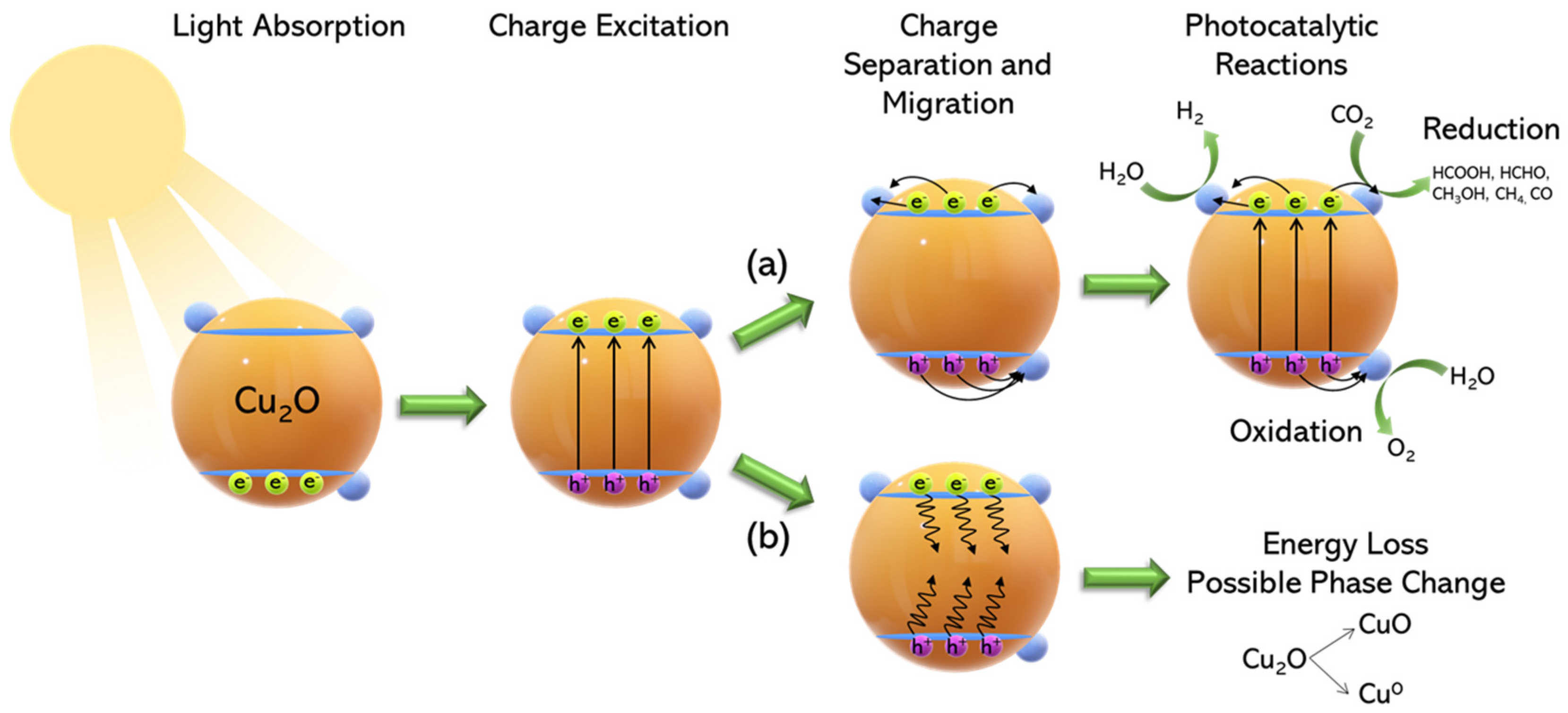
Figure 1. Schematic description of the photoexcitation-related reaction paths in Cu2O semiconductors in path (a) electron-hole pairs are utilized for “Artificial-Photosynthesis”. In path (b), detrimental phase-transformation can occur due to photocorrosion.
Solar 03 00008 g001
Figure 2. The photocorrosion pathways can involve either “self−oxidation” or “self−reduction” of Cu2O. This is related to the positions of the redox couples Cu1+/Cu2+ and Cu1+/Cu0 relative to the EVBand and ECBand edges.
Solar 03 00008 g002
Figure 3. Various Case-Studies exemplifying methods to address the problem of photocorrosion. CaseStudy A: Energy band diagram of Cu2O/TiO2 composite (top) and normalized spectral responses (bottom). Reprinted from [19]. Copyright 2003, with permission from Elsevier; CaseStudy B: Schematic illustration of charge separation-transfer of CuO/Pt composite photocathode during photoelectrochemical (PEC) water splitting. Reproduced from Ref. [26] with permission from the Royal Society of Chemistry; CaseStudy C: SEM images of cubic-Cu2O NPs showing the effect of hole and electron scavenger. Reproduced with permission from ref. [31]. Copyright 2018 Wiley−VCH; CaseStudy D: Charge transfer in Cu2O/RGO composites facilitating photocatalytic conversion of CO2. Reproduced with permission from ref. [32]. Copyright 2014 Wiley−VCH; CaseStudy E (Alloy): Calculated adsorption free energy diagram for the Volmer step (left) and for the Tafel step (right). Reprinted with permission from [28]. Copyright 2020 American Chemical Society; CaseStudy E (Core-Shell): Nyquist plots of various NiCu catalysts. Reproduced with permission from ref. [33]. Copyright 2017 Wiley-VCH; CaseStudy F: Nyquist plots and long-term stability (30 h) of PS-Cu, Cu NPs, and Cu foam. Reproduced with permission from ref. [27]. Copyright 2022 Wiley−VCH.
Solar 03 00008 g003
Figure 4. The redox-potential of some commonly used organic hole-scavengers as well as of SO32−: the more negative potential of the SO42−/SO32− couple can provide a more efficient protection against self−photo−oxidation of Cu2O [31,41].
Solar 03 00008 g004
Figure 5. (a) EIS of composite electrodes to exploit the charge transfer resistance of pristine Cu2O and Cu2O/reduced graphene oxide and subplot of SEM image of Cu2O/RGO composites. Reproduced with permission from ref. [32]. Copyright 2014 Wiley−VCH. (b) Long−term durability of Cu/Cu2O−CuO/rGO−400 and subplot is a SEM image of the same sample. Reproduced from Ref. [44] with permission from the Royal Society of Chemistry. (c) Electrochemical impedance spectroscopy of CG catalysts and Cu2O in 1 M KOH with subplot of a SEM image of CG5 after 8 h reaction. Reprinted from [45], with permission from Elsevier. (d) Raman spectra for alloyed Ni−Cu encapsuled in graphitic shells with different thickness with thickness to be increasing downwards and TEM images of the NiCu@C−1 sample. Reproduced with permission from ref. [33]. Copyright 2017 Wiley−VCH.
Solar 03 00008 g005
Figure 6. (a) Schematic representation of a stable alloy of CuRu nanoparticle for Hydrogen Evolution Reaction; (b) Stability tests of the Cu53Ru47 in neutral (1 M PBS) and in alkaline (1 M KOH) environment; (c) Schematic illustration of the preparation procedure by dealloying a single−phase ternary Ru3Cu22Mn75 precursor in (NH4)2SO4 solution to remove Mn. Reprinted with permission from [28]. Copyright 2022 American Chemical Society.
Solar 03 00008 g006
Figure 7. Electrocatalytic Hydrogen Evolution Reaction in Acidic and Alkaline Conditions. A summary of pertinent Cu-based semiconducting materials is listed on Table 2 (photocatalytic H2 production), Table 3 (electrocatalytic H2 production) and Table 4 (photoelectrocatalytic H2 production). Hereafter, we highlight some engineering aspects related to the control/improvement of hydrogen evolution by such catalysts.
Solar 03 00008 g007
Figure 8. (a,b) XPS spectra of Cu 2p of Cu2O and C−1.5/T−2 and Ti 2p of T−2 material, respectively. For C−1.5/T−2 nanocomposite we observe a negative shift of 0.1 eV (binding energy of Cu 2p) and a positive shift of 0.2 eV (binding energy of Ti 2p) indicating that the electron density of Ti (IV) decreases and that of Cu(I) increases, which may indicate a directional carrier transfer from TiO2 to Cu2O; (c) ESR spectra of T−2, C−1.5/T-2 and C−1.5/T−2, where the characteristic OV signal can be seen confirming the existence of oxygen vacancies; (d) Proposed Z-scheme mechanism of Cu2O/TiO2 composite. Reprinted from [58] with permission from Elsevier; (e) Cu nanoparticles with an average size of 2 nm deposited on the surface of TiO2; (f,g) Proposed H2 evolution mechanism for the initial Cu/TiO2 composite where photogenerated electron reduce CuO to Cu2O; (h) Cu/TiO2 composite where under illumination metallic Cu NPs enhance H2 production due to SPR. Reprinted from [59] with permission from Elsevier.
Solar 03 00008 g008
Figure 9. (a) TEM−SAED−HRTEM images of the Cu@Cu2O/ZnO nanocomposite; (b) Photocatalytic stability experiments of the Cu@Cu2O/ZnO (30wt%) where after four catalytic runs there was no significant decrease of the performance; (c) H2 production rates of Cu@Cu2O/ZnO catalysts where 30% copper loading shows the best photocatalytic performance; (d) Proposed photocatalytic H2 production mechanism of the Cu@Cu2O/ZnO under visible light irradiation. Reproduced with permission from ref. [62], Copyright 2018 Wiley−VCH; (e) Tauc plots of Cu2O, ND and NDs−Cu2O where the addition of NDs decreases the energy gap of Cu2O. (f) Schematic representation of the photocatalytic mechanism of NDs−Cu2O; Reproduced with permission from ref. [65], Copyright 2015 Wiley−VCH.
Solar 03 00008 g009
Figure 10. Electrocatalytic HER performance of Cu−m/Cu−W/NiCo−LDH as a competitive catalyst against the state of art 40% Pt/C. Alkaline conditions (1 M KOH) (a) HER polarization curves in 1 M KOH (iR−corrected); (b) overpotentials at −10 and −100 mA cm−2; (c) Tafel plots for Cu−m/Cu−W/NiCo−LDH and 40 wt% Pt/C. For acidic conditions (0.5 M H2SO4): (d) HER polarization curves (iR−corrected); (e) overpotentials at −10 and −100 mA cm−2; (f) corresponding Tafel plots; (g) high resolution TEM images of Cu−m/Cu−W/NiCo−LDH; (h) Required overpotential across the pH spectrum to reach −10 mA cm−2 for Cu−m/Cu−W/NiCo−LDH and 40 wt% Pt/C. Reproduced from Ref. [79] with permission form the Royal Society of Chemistry; Photo−electrochemical HER of CuO with CuO, CuO/TiO2, CuO/Pt and CuO/TiO2/Pt photocathodes. (i) SEM image of the last sample CuO/TiO2/Pt is presented with elemental mapping images of Cu, O, Ti and Pt of CuO/TiO2/Pt. (j) Photocurrent density versus Applied Voltage, with the CuO/TiO2/Pt to behave better of all other samples. (k) The photo-response of samples measured at −0.55 V vs. Ag/AgCl under illumination with 30 s light on/off cycles, while (l) presents Photocurrent density−time curves measured in 1 M NaOH electrolyte at −0.55 V vs. Ag/AgCl under simulated sunlight illumination for 2 h, indicating a stable sample and (m) Nyquist plots by Electrochemical Impedance Spectroscopy measured at −0.55 V vs. Ag/AgCl of photocathodes with the CuO/TiO2/Pt to has the smaller arc-radius. Reproduced from Ref. [26] with permission from the Royal Society of Chemistry.
Solar 03 00008 g010
Figure 11. Band positions of various metal oxide and non−oxide semiconductors and 2D materials. Reproduced from Ref. [86] with permission from the Royal Society of Chemistry.
Solar 03 00008 g011
Figure 12. (a) SEM images of Cu2O (top) and Cu2O/TiO2 composite (bottom) where the surface of Cu2O octahedral particles is covered with TiO2 NPs; (b) Schematic presentation of the proposed CO2 reduction mechanism induced by λ ≥ 305 nm; (c) XPS spectra for Cu 2p3/2 for pristine Cu2O (top) and Cu2O/TiO2 (bottom). Reprinted from [67], with permission from Elsevier; (d) CH3OH yields of CuO, rGO−CuO and rGO−Cu2O composites; (e) Schematic representation of the CO2 conversion mechanism to CH3OH using the rGO−CuO116 composite under visible light irradiation; (f) Stability/recycling experiments of rGO−CuO116. Inset figure shows CH3OH yields after 6 consecutive catalytic runs. Reprinted from [100] with permission from Elsevier.
Solar 03 00008 g012
Table 1. Overall reaction pathways for HER in acidic/alkaline mediums.
Overall Reaction (Conditions)Reaction PathwayEquations
Acidic Media
2 { H + } + 2 { e } H 2
{ H + } + { e } +   *   H *   ( Volmer ) 1.i
{ H + } + { e } +   H * H 2   ( Heyrovsky ) 1.ii
or   H * +   H * H 2   ( Tafel ) 1.iii
Alkaline Media 2 H 2 O + 2 { e }   H 2 + 2 OH H 2 + { e } H * + OH   ( Volmer ) 2.i
H 2 O + { e } +   H * H 2 + OH   ( Heyrovsky ) 2.ii
or   H * +   H * H 2   ( Tafel ) 2.iii
Table 3. Summary of Electrocatalytic Parameters, related to Hydrogen Evolution Reaction, for Cu-based catalysts.
Electrocatalytic Hydrogen Production
CatalystElectrolyte or pHCdl (mF/cm2)η(mV) @ −10 mA/cm2Tafel Slope (mV dec−1)Ref.
Cu/Cu2O-CuO/rGO-4001 M KOH130105124[44]
PS-Cu0.5 M H2SO48.7718299.16[27]
1 M PBS10.01261143.58
1 M KOH13.56121136.54
Cu-foam0.5 M H2SO44.86411192.22
1 M PBS5.60429211.95
1 M KOH5.91473230.27
Cu-NPs0.5 M H2SO46.87530132.17
1 M PBS6.47707285.99
1 M KOH9.72454148.86
Pt-foil0.5 M H2SO4 7879.09
1 M PBS 186194.05
1 M KOH 178167.84
NiCu@C-1pH = 0 4894.5[33]
pH = 7 16494.6
pH = 14 7474
Graphene coated Cu0.5 M H2SO4 25267[77]
Cu@NC NT/CF-5001 M KOH10112361[78]
Cu53Ru471 M KOH591530[28]
1 M PbS594135
Cu-m/Cu-W/NiCo-LDH0.5 M H2SO4 1579.4[79]
1 M KOH19.82750.5
Table 5. Pertinent Cu-based semiconductors used for the photocatalytic CO2 conversion into various chemical fuels.
Photocatalytic CO2 Reduction
CatalystHole Scavenger/
Reaction Conditions
Irradiation SourceMain ProductsRef.
(110) Cu2OSaturated H2O in CO2 300 W Xe-LampCH3OH: 1.2 mol g−1 h−1[90]
Dodeca-Cu2O/rGOSaturated H2O in CO2300 W Xe-Lamp (λ ≤ 420 nm)CH3OH: 355.3 μmol g−1 h−1[91]
Pt-Cu2O/TiO2Saturated H2O in CO2 (71kPa)500 W Xe-arc Lamp (300 nm < λ < 400 nm) (20.5 mW cm−2)CH4: 1.42 μmol g−1 h−1
CO: 0.05 μmol g−1 h−1
[92]
Octa-Cu2O/TiO2Water vapor—1atm CO2 (g)1 kW Hg (Xe) arc lamp (λ ≥ 305 nm)CO: 2.11 μmol g−1 h−1[67]
1% Cu/TiO2 (H2)Mixed gas CO2/H2O150 W solar simulator (90 mW cm−2, 200 ≤ λ ≤ 1000 nm)CH4: 25 μmol g−1 h−1
CO: 4.4 μmol g−1 h−1
[93]
2%CuO-19%ZnO/TiO2 Saturated H2O in CO2, 0.2 M NaOH18 W Hg-Lamp (λ = 25 4nm)CH4: 184 μmol g−1 (after 24 h)[94]
ZnO-Cu2OSaturated H2O in CO2, 0.2 M Na2CO3300 W Xe-Lamp CH4: 1080 μmol g1 h−1[95]
5wt% CuO/NaTaO3CO2, Isopropanol250 W Hg-Lamp (365 nm)CH3OH: 1302.22 μmol g−1 h−1[96]
Cu2OSaturated H2O in CO2, NaOH, Na2SO3500 W Xe-arc Lamp (400 nm < λ < 700nm)CH3OH: 104 μmol g−1[97]
Cu2O-SiCCH3OH: 191 μmol g−1
BiVO4/C-coated Cu2OSaturated H2O in CO2300 W Xe-Lamp (100 mW cm−2) (λ > 420 nm) CO: ~3 μmol g−1 h−1[98]
3%Cu/TiO2Saturated H2O in CO2, 1 M NaOHUV-Lamp (254 nm, 5.4 mW cm−2)
Visible: 500 W Xe-arc Lamp
HCOOH: > 4500 μmol g−1 h−1 (Visible) // CH3OH: ~300 μmol g−1 h−1 (Visible)
HCOOH: >2000 μmol g−1 h−1 (UV)// CH3OH: >75 μmol g−1 h−1 (UV)
[99]
3% Cu/g-C3N4HCOOH: >3500 μmol g−1 h−1 (Visible)//CH3OH: ~350 μmol g−1 h−1 (Visible)
HCOOH: >3750 μmol g−1 h−1 (UV)// CH3OH: >200 μmol g−1 h−1 (UV)
(g-C3N4)/(3%Cu/TiO2) (30:70)HCOOH: 5069 μmol g−1 (Visible)//
CH3OH: 2574 μmol g−1 (Visible)
HCOOH: 6709 μmol g−1 (UV)//
CH3OH: 614 μmol g−1 (UV)
rGO-CuODMF, Saturated H2O in CO220 W LED (85 W m−2)CH3OH: 1228 μmol g−1[100]
rGO-Cu2OCH3OH: 862 μmol g−1
c-Cu2O_gCN~1 bar CO2 with moisture8 W LED LampCO: 0.002 μmol g1 h−1[101]
g-C3N4/CuO@MIL-125(Ti)H2O 0.3%CO2 (1 MPa)300 W Xe-Lamp (326.1 W m−2) (λ = 420 nm)CO: 180.1 μmol g−1
CH3OH: 997.2 μmol g−1
C2H5OH: 531.5 μmol g−1
CH3CHO: 1505.7 μmol g−1
[102]
Disclaimer/Publisher’s Note: The statements, opinions and data contained in all publications are solely those of the individual author(s) and contributor(s) and not of MDPI and/or the editor(s). MDPI and/or the editor(s) disclaim responsibility for any injury to people or property resulting from any ideas, methods, instructions or products referred to in the content.