Article

Electrochemical Analysis of Corrosion Resistance of Manganese-Coated Annealed Steel: Chronoamperometric and Voltammetric Study

by
Francisco Augusto Nuñez Pérez
Maestría en Ciencias en Ingeniería, Universidad Politécnica de Lázaro Cárdenas, Lázaro Cárdenas C.P. 60998, Michoacán, Mexico
AppliedChem 2024, 4(4), 367-383; https://doi.org/10.3390/appliedchem4040023
Submission received: 1 August 2024 / Revised: 11 September 2024 / Accepted: 16 September 2024 / Published: 19 November 2024

Abstract

:
Metal corrosion poses a significant challenge for industries by decreasing the lifespan of materials and escalating maintenance and replacement costs. This study is critically important, as it assesses the corrosion resistance properties of annealed steel wire electrodes coated with manganese, employing chronoamperometry and linear voltammetry techniques. The electrodes were immersed in an electrolyte solution and subjected to chronoamperometry at various voltages (−0.55 V, −0.60 V, and −0.70 V) and durations (60 s and 1800 s). Subsequently, linear voltammetry was performed over a potential range from −0.8 V to 0.8 V to generate Tafel plots. The Butler–Volmer equation was applied to the data obtained to determine the corrosion current density. The results indicate that the optimal conditions for forming a highly effective protective manganese layer occur at a potential of −0.70 V for 1800 s. Under these conditions, the electrodes exhibited superior corrosion resistance. This study also revealed that shorter durations and less negative potentials led to less-effective manganese coatings, with higher corrosion rates and reduced stability. These findings are significant for developing efficient corrosion protection methods in industrial and research applications, providing clear parameters for optimizing the manganese electrodeposition process on annealed steel.

1. Introduction

Manganese sulfate monohydrate is a widely used inorganic compound used in agriculture as a fully soluble fertilizer [1]. However, beyond its agronomic benefits, manganese holds significant potential in the field of electrochemical corrosion protection, where it has been shown to effectively inhibit corrosion processes in various environments [2,3,4] Corrosion is the degradation of metals due to chemical or electrochemical reactions with their environment, leading to continuous wear and potential material failure over time [5,6,7,8].
This degradation constitutes a critical concern across various industrial applications where the integrity and longevity of metal structures are essential [9,10]. In coastal environments, the corrosion of structural steel is significantly aggravated by high humidity levels, which accelerates the corrosion process and substantially increases maintenance and repair costs. Recent studies have quantified that the costs associated with corrosion account for from approximately 3% to 4% of the GDP in industrialized nations, underscoring its significant global economic impact. The implementation of advanced corrosion control techniques is crucial not only for preserving infrastructure, but also for achieving substantial annual cost savings [11,12,13].
Manganese, as a corrosion inhibitor, offers a promising solution. Manganese compounds can form protective films on metal surfaces, acting as barriers that limit the interaction between the metal and the corrosive environment. Additionally, manganese can participate in electrochemical reactions that alter the base metal’s corrosion potential, making it less susceptible to oxidation. This ability to modify the electrochemical environment is particularly useful in systems where continuous and effective corrosion protection is required [2,3].
It has been demonstrated that the implementation of manganese compounds can significantly improve the corrosion resistance of metal structures. However, despite the solid foundation provided by previous studies, there is limited information on optimizing electrodeposition conditions and their impact on the long-term durability of manganese coatings [5,6,7,8,9,10]. A significant part of electrochemistry focuses on optimizing the application of manganese compounds for corrosion protection, evaluating their effectiveness under different environmental conditions and on various materials. This includes studies on film formation kinetics, film adherence under dynamic conditions, and interactions with other elements present in industrial environments [11,12,13,14]. Furthermore, combinations of manganese with other corrosion inhibitors are being explored to create multifunctional protection systems that can offer robust and durable defense against electrochemical degradation.
In summary, integrating manganese into corrosion protection strategies represents a valuable avenue for research and practical application. Ongoing innovation in this field is essential to address the persistent challenges that corrosion poses to industrial infrastructure, ensuring the integrity and longevity of metal structures in various critical applications. Future developments in corrosion protection technologies will not only enhance industrial sustainability and economics, but also contribute to long-term safety and environmental protection.
This study explored various methodologies to investigate the electrochemical properties of manganese coatings in protecting annealed steel electrodes against corrosion. The chosen approach focused on oxidation and reduction reactions, using advanced electrochemical techniques to deposit and evaluate manganese coatings [15]. Three types of electrodes were employed in the electrochemical cell setup: a working electrode, a reference electrode, and a counter electrode.
Working electrode: This is the site of reduction where metal ions are deposited and the desired electrochemical reaction occurs. In this study, annealed steel wire was used as the working electrode. Reference electrode: It maintains a stable and known potential, serving as a reference point for measuring the working electrode’s potential. An Ag/AgCl electrode was used due to its stable potential in aqueous solutions. Counter electrode: Made of a material with negligible electrochemical activity, the counter electrode completes the electrical circuit and allows for current flow through the cell. Graphite was chosen for its inert properties in the studied electrochemical reactions.
The objective of this research was to optimize the conditions for manganese electrodeposition on annealed steel to enhance corrosion resistance. Using chronoamperometry and linear voltammetry techniques, this study systematically investigated the effect of various voltages and durations on the formation and effectiveness of manganese coatings.
This study presents an innovative approach to optimizing electrochemical conditions for manganese electrodeposition on annealed steel, emphasizing its impact on corrosion resistance. Unlike previous research that focused on deposit morphology, this work centers on a detailed electrochemical analysis of the coating properties, employing advanced techniques such as electrochemical impedance spectroscopy (EIS) and linear voltammetry. The results demonstrate that a potential of −0.70 V applied for 1800 s is optimal for producing a protective manganese layer with excellent corrosion resistance, as validated using precise measurements of corrosion current density and charge transfer capacity.
These findings offer a new perspective on optimizing the electrodeposition process, highlighting the critical role of electrochemical conditions in enhancing the durability and effectiveness of metallic coatings. The use of advanced electrochemical techniques enables a comprehensive and precise characterization of the coating, underscoring the importance of electrodeposition parameters for industrial applications that demand high standards of corrosion protection.
These findings provide a new perspective on the optimization of the electrodeposition process, highlighting the importance of electrochemical conditions in enhancing the durability and effectiveness of metallic coatings. The use of advanced electrochemical techniques allows for a comprehensive and precise characterization of the coating, emphasizing the significance of electrodeposition parameters for industrial applications that demand high standards of corrosion protection [15]. Moreover, electrodeposition is a low-cost alternative that offers a high degree of control during nucleation and growth, without requiring hazardous experimental conditions [16,17,18]. Steel is widely used in industry due to its low cost and recyclability, although its low corrosion resistance limits its use. To protect it, galvanized coatings are applied, with electrodeposition being a common technique [19]. Advanced electrochemical techniques, including chronoamperometry and linear voltammetry, were utilized to analyze and characterize the kinetics of corrosion [20,21,22].

2. Materials and Methods

This work focuses on the corrosion properties of manganese coatings electrodeposited on annealed steel wires using electrochemical methods. The reagents, manganese sulfate monohydrate (MnSO4·H2O) and potassium chloride (KCl), were purchased from Sigma-Aldrich, St. Louis, MO, USA, ensuring high purity and consistency. Solutions were prepared at concentrations of 0.03 M and 0.09 M, respectively, using demineralized water with a resistivity of 18 MΩ·cm.
For the preparation of these solutions, an OHAUS Explorer® analytical balance with a capacity of 220 g and a precision of 0.0001 g was used. This balance, regularly calibrated, ensures accuracy in measuring the masses needed to achieve the precise concentrations of the reagents in solution. The reagents were carefully weighed and dissolved in 500 mL volumetric flasks, adjusting the final volume with demineralized water to ensure the required molar accuracy. The manganese electrodeposition was conducted in a three-electrode electrochemical cell. The working electrode was an annealed steel wire, partially covered with silicone or clear enamel, with an exposed section polished with fine sandpaper to ensure a clean, oxide-free surface. The reference electrode was a Metrohm® Ag/AgCl electrode, known for providing a stable and constant reference potential in aqueous solutions [23,24]. The counter electrode was graphite, chosen for its chemical inertness and stability under experimental conditions [25]. All of the electrodes were meticulously prepared to ensure cleanliness and suitability for electrochemical experiments.
The electrochemical cell temperature was maintained at 25 °C using a thermostated water bath, ensuring controlled conditions throughout the experiments. A nitrogen purging system was used to deoxygenate the solution for 5 min before each experiment, preventing unwanted oxidation [22]. The electrochemical experiments were conducted using a rigorously calibrated Metrohm® AUTOLAB PGSTAT302N potentiostat/galvanostat, synchronized with a computer equipped with NOVA software for data acquisition and analysis. This equipment, with an applied potential accuracy of ±0.2% ±2 mV and a resolution of 150 μV, allowed for precise control of the applied potentials and the collection of high-quality electrochemical data. Additionally, it features a minimum measured potential resolution of 0.3 μV and a potentiostat bandwidth greater than 1 MHz, ensuring a rapid and precise response during the experiments. The equipment also has the capability to measure currents with a resolution of 30 fA, making it ideal for experiments that require high sensitivity and precision.
Chronoamperometry experiments were performed at potentials of −0.55 V, −0.60 V, and −0.70 V for 60 s and 1800 s, respectively, for manganese deposition. Subsequently, linear voltammetry sweeps from −0.8 V to 0.8 V were conducted relative to the Ag/AgCl reference electrode to investigate the corrosion rate of the coated electrodes. The initial chronoamperometry and voltammetry experiments were conducted in demineralized water to establish a controlled baseline and to evaluate the intrinsic electrochemical behavior of the manganese coatings without the influence of aggressive ions, such as chlorides, commonly found in saline solutions. This approach allows for a more precise assessment of the stability and uniformity of the manganese layer under idealized conditions. Cyclic voltammetry curves were obtained through multiple scans at a scan rate of 0.01 V/s, with a step potential of 0.00244 V, and a potential range from −0.8 V to 0.8 V. These parameters were chosen to assess the stability and reproducibility of the manganese coating. While it is generally accepted that corrosion tests are performed in 1% or 3% NaCl solutions, the use of demineralized water in this study was intended to isolate and understand the electrochemical characteristics of the coating before exposing it to more corrosive environments [26,27].
The data obtained were analyzed using the Butler–Volmer equation to calculate the corrosion current density (icorr) and corrosion rate. Electrochemical impedance spectroscopy (EIS) was conducted using an annealed steel wire as the working electrode, with manganese sulfate monohydrate (MnSO4 H2O) and potassium chloride (KCl) solutions as the electrolytes. The frequency range analyzed spanned from 100 mHz to 100 kHz, with an AC perturbation signal amplitude of 10 mV. Nyquist and Bode plots were generated to evaluate charge transfer resistance and double-layer capacitance. These analyses provided a detailed understanding of the efficiency and uniformity of the manganese coatings, allowing for the optimization of electrodeposition conditions to enhance corrosion resistance.
The reproducibility of the results was verified through the comparison of multiple scans and repeated experiments, ensuring data consistency. Following established methodologies as described in previous studies [21,22], kinetic and thermodynamic parameters, such as Tafel coefficients, were determined from the logarithmic plots of current density versus potential. Corrosion current density and corrosion rates were calculated based on these well-established procedures, providing a detailed assessment of the corrosion kinetics and the quality of the manganese coatings. This approach enabled a comprehensive evaluation of the electrochemical performance of the coatings under various deposition conditions.

3. Results

3.1. Open Circuit Potential (OCP) Evaluation

The stability and robustness of the Open Circuit Potential (OCP) are fundamental prerequisites for ensuring the consistency and reliability of subsequent electrochemical experiments, such as chronoamperometry and linear voltammetry. The OCP evaluation was performed in a solution of manganese sulfate monohydrate (MnSO4·H2O) and potassium chloride (KCl), using bare annealed steel wire. This step was critical for establishing the appropriate deposition potentials before forming the manganese coating. The OCP was monitored for up to 60 s, but in practice, stabilization often occurred within 0.8 s. This process ensured that the electrodes reached an equilibrium state before applying external potentials, which is essential for obtaining accurate and reproducible results in the subsequent electrochemical analyses. This OCP evaluation is separate from the actual electrodeposition time, serving only as a preparatory step to ensure stable initial conditions [28].
In Figure 1, the Open Circuit Potential (OCP) voltage recorded for manganese-coated annealed steel electrodes is presented. The OCP voltage remained constant over time, indicating high system stability. This stability is critical, as any significant fluctuations in the OCP could adversely affect the outcomes of subsequent experiments.

3.2. Cyclic Voltammetry

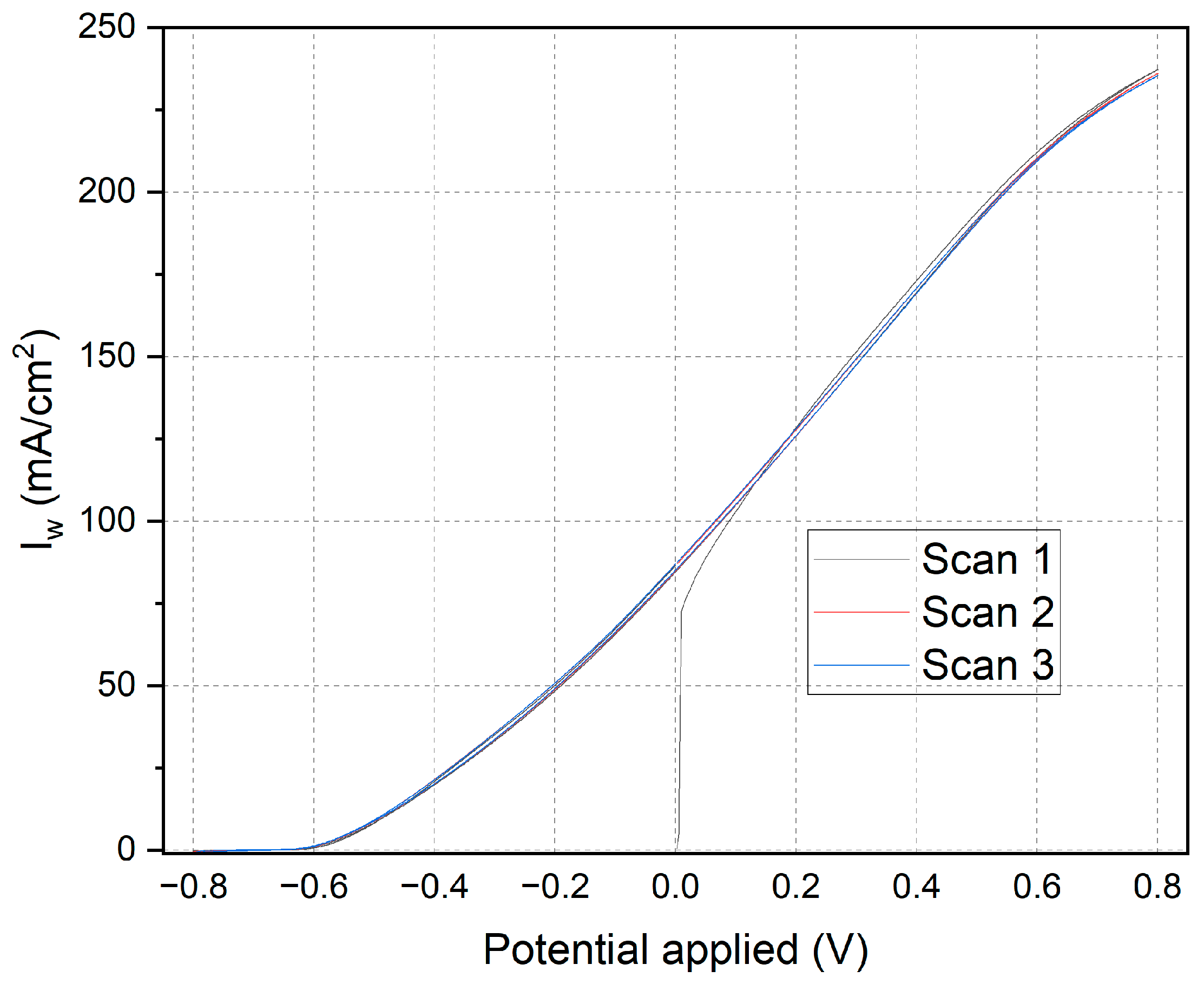
Figure 2 illustrates the cyclic voltammetry curves obtained over the full potential range from −0.8 V to 0.8 V relative to the reference electrode (Ag/AgCl) for annealed steel electrodes in manganese sulfate and potassium chloride solutions. The curves from three consecutive scans (Scan 1, Scan 2, Scan 3), which each represent a complete forward and backward sweep, demonstrate remarkable reproducibility, indicative of well-controlled experimental conditions. Although the current density should ideally reach zero at 0 V with respect to the open circuit potential (OCP), in this setup, the potential range is referenced against the Ag/AgCl electrode. The observed shift in the zero-current potential is consistent with the specific experimental setup, where the current density consistently increases with applied potential, characteristic of systems involving significant redox processes. This broader view is essential for validating the overall electrochemical behavior of the system across multiple scans, confirming stability and reproducibility.
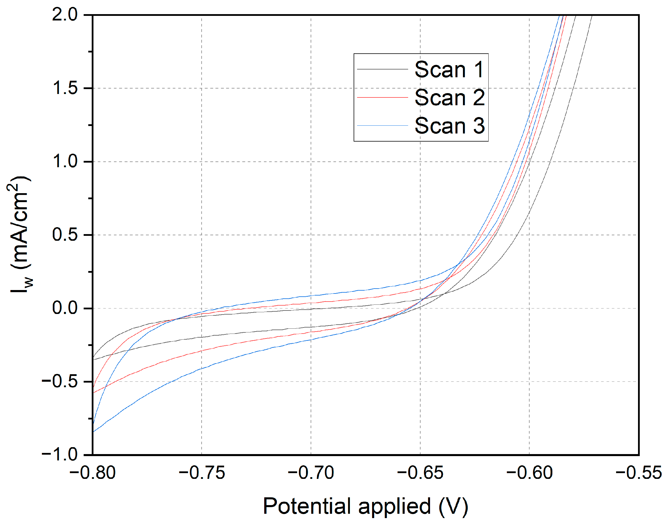
Figure 3 focuses specifically on the potential range from −0.8 V to −0.55 V, zooming in on the region where the reduction of Mn2+ to Mn is most pronounced. This zoomed-in view provides a detailed analysis of the reduction process, which is critical for understanding the effectiveness of manganese electrodeposition. Similar to Figure 3, the curves from three consecutive scans exhibit high reproducibility, but Figure 4 specifically highlights the critical potential region where the Mn2+ reduction occurs near equilibrium conditions. This detailed examination allows for a more precise evaluation of the electrodeposition efficiency and the stability of the manganese layer being formed. Both figures serve different purposes: Figure 3 provides a comprehensive overview, while Figure 4 offers an in-depth look at the key reduction process, ensuring a thorough understanding of the electrochemical behavior under the experimental conditions.
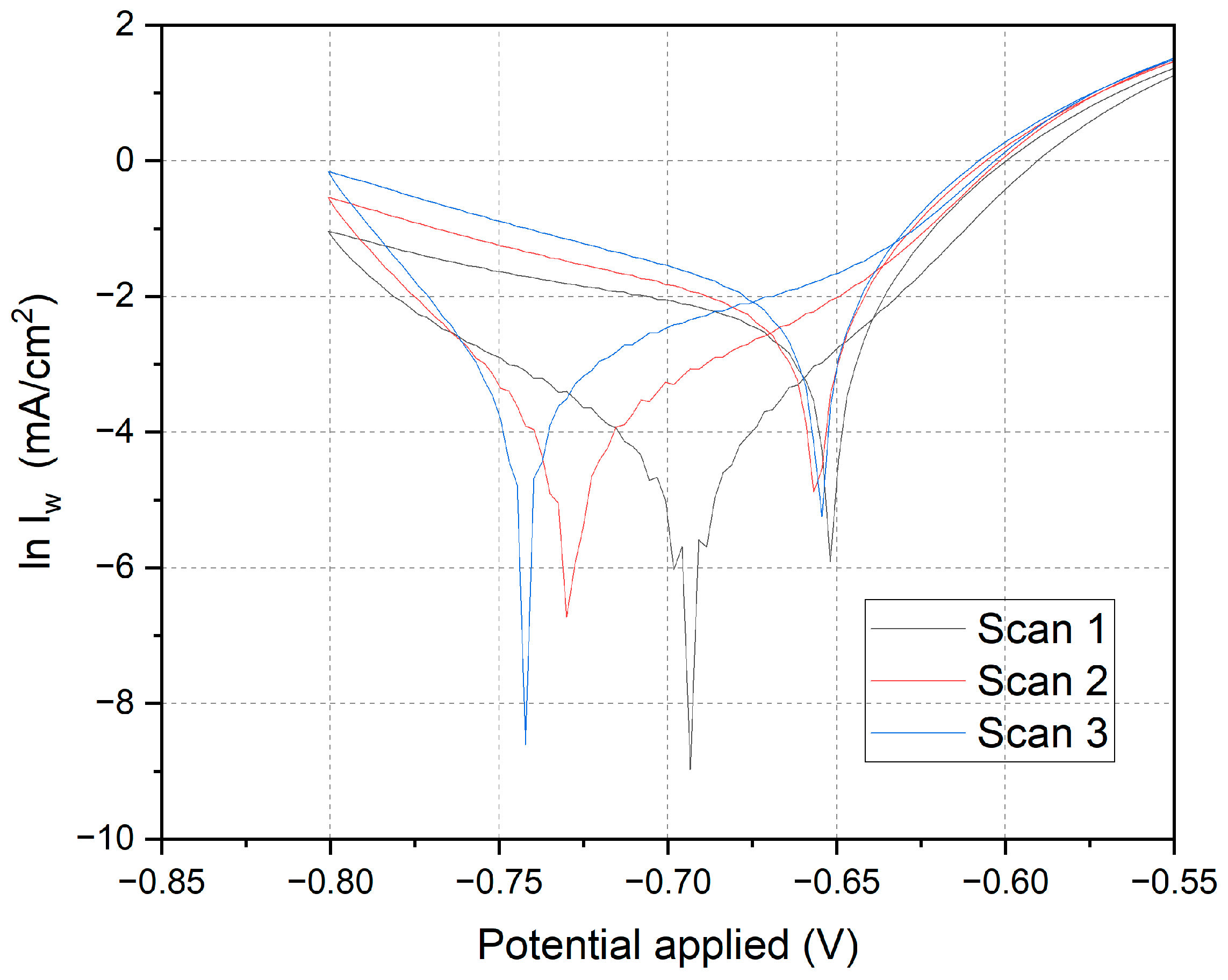
Figure 4 presents the cyclic voltammetry curves for annealed steel electrodes, with the natural logarithm (ln) applied to the current density (Iw). Three consecutive scans (Scan 1, Scan 2, and Scan 3) were conducted over a potential range from −0.80 V to −0.55 V to identify kinetically controlled processes and evaluate charge transfer behavior in the reduction and oxidation of Mn2+.
The logarithmic transformation clarifies changes in current density, enhancing the visualization and analysis of charge transfer processes and kinetically controlled behaviors in the electrochemical system. The curves exhibit a characteristic inverted “V” shape, indicating the presence of reversible redox processes, with a minimum in the cathodic region followed by an ascending section corresponding to anodic oxidation. This behavior is typical in electrochemical systems with alternating reduction and oxidation processes.
The observed minima correspond to cathodic peaks where Mn2+ is reduced to metallic Mn. The subsequent ascending sections represent the reoxidation of metallic Mn back to Mn2+.

3.3. Chronoamperometry

A potential of −0.70 V was chosen due to its proximity to the cathodic peak observed in cyclic voltammetry, where the reduction of Mn2+ to Mn is most pronounced. This potential ensures effective and consistent Mn2+ reduction, providing excellent manganese coverage on the electrode, which is crucial for maximizing corrosion resistance.
A potential of −0.60 V was selected to explore a slightly less negative range, assessing the efficiency of Mn2+ reduction under conditions with significant cathodic current but reduced capacitive and transient effects. This allows for a precise comparative evaluation of the manganese coating’s quality and characteristics formed under different electrochemical conditions.
A potential of −0.55 V was chosen to investigate the system’s behavior at an even less negative potential, where Mn2+ reduction is less favorable. This helps to evaluate the impact of a potential closer to the OCP on the manganese coating formation, determining the minimum energy required for effective reduction and allowing for a critical comparison with results at −0.70 V and −0.60 V.
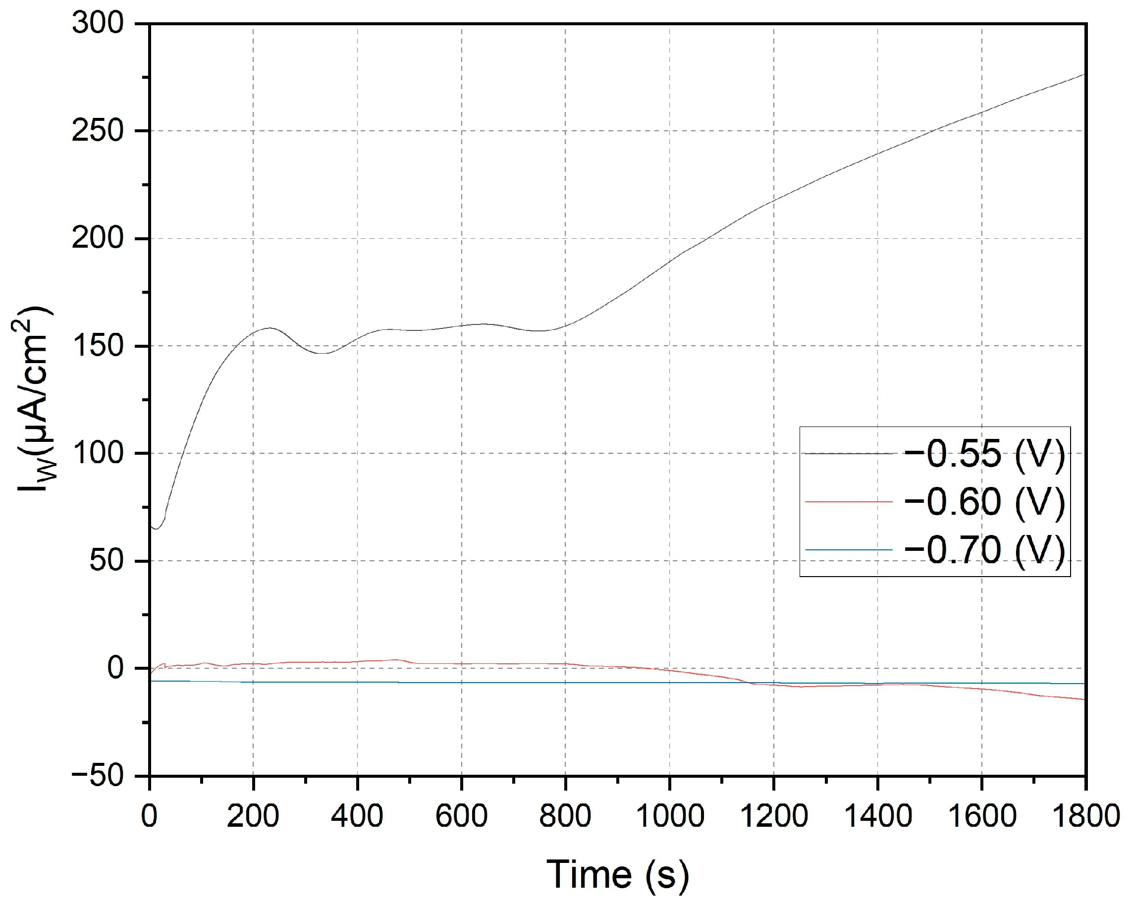
Figure 5 shows the current density (Iw) versus time for three applied potentials. At −0.55 V (black line), the initial current density is approximately 150 μA/cm2, gradually increasing to over 250 μA/cm2 by the experiment’s end. This behavior indicates significant oxidation on the annealed steel electrode, likely described by the reaction:
Fe (s) → Fe2+(aq) + 2e
The KCl in the solution enhances ionic conductivity, facilitating ion transport and improving the kinetics of electrochemical reactions. Cl ions can penetrate oxide layers on metals, promoting the formation of soluble corrosion products and continuous iron oxidation.
Effect of manganese sulfate (MnSO4·H2O): Mn2+ in the solution can influence passive layer formation on steel. While Mn2+ ions do not directly participate in iron oxidation, their presence can alter the properties of the oxide film, potentially making it more porous and allowing for sustained oxidation.
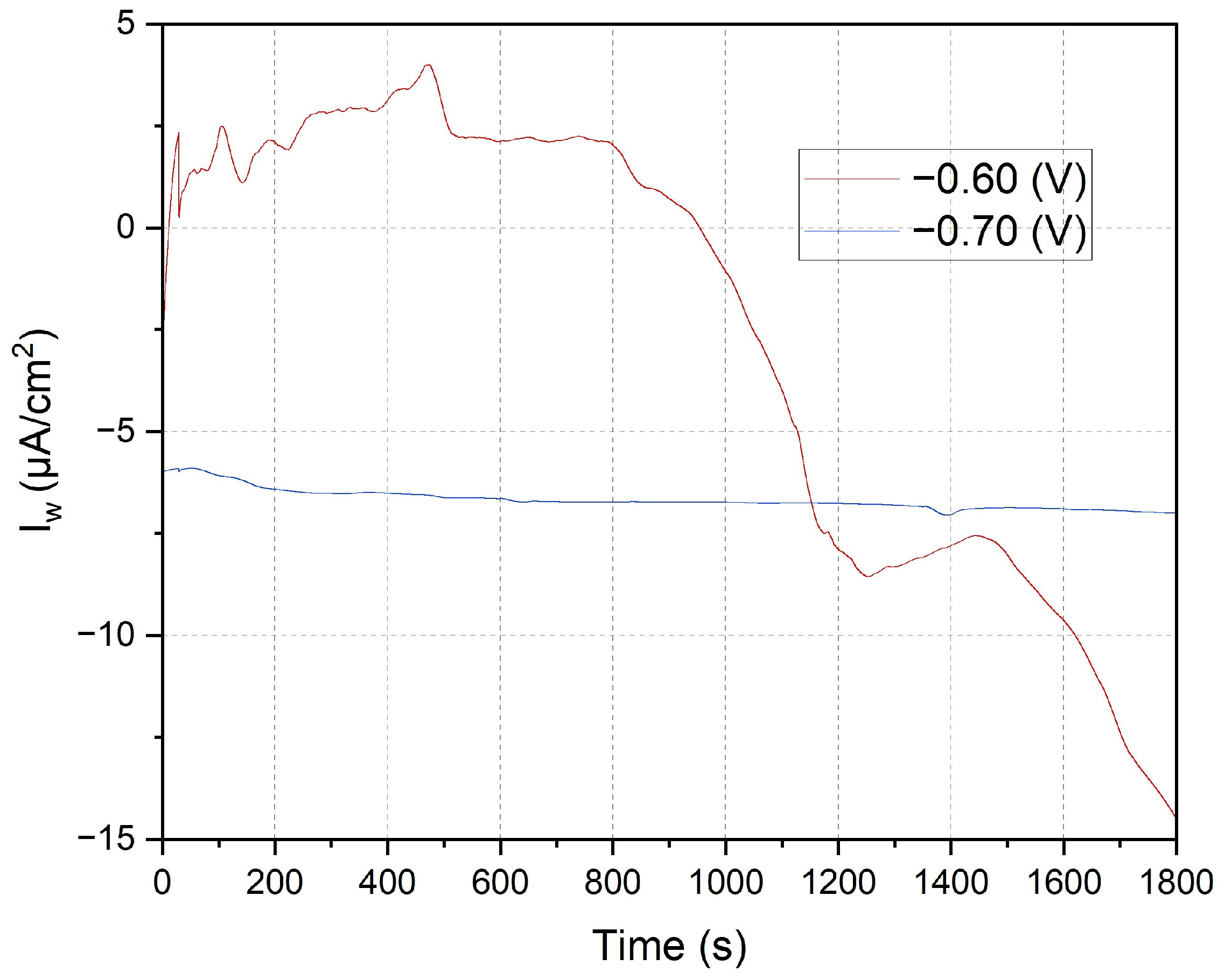
Figure 6 displays the chronoamperometry curves obtained at potentials of −0.60 V and −0.70 V over 1800 s. The variations in current density highlight critical differences in electrochemical behavior and the effectiveness of Mn2+ reduction under different potential conditions.
This study confirms that chronoamperometry at varying potentials accurately evaluates manganese electrodeposition efficiency and its impact on the corrosion resistance of annealed steel. Results show that −0.70 V provides uniform and highly effective manganese coverage, significantly reducing corrosion current density. MnSO4·H2O and KCl solutions play crucial roles in coating formation and stability, enhancing the protective properties of the steel electrode.
These findings provide a robust basis for optimizing manganese electrodeposition conditions, improving the durability and corrosion resistance of metallic coatings in industrial and research applications. A detailed understanding and control of these electrochemical processes are essential for advancing corrosion protection, significantly extending the lifespan of critical metal structures.

3.4. Linear Voltammetry

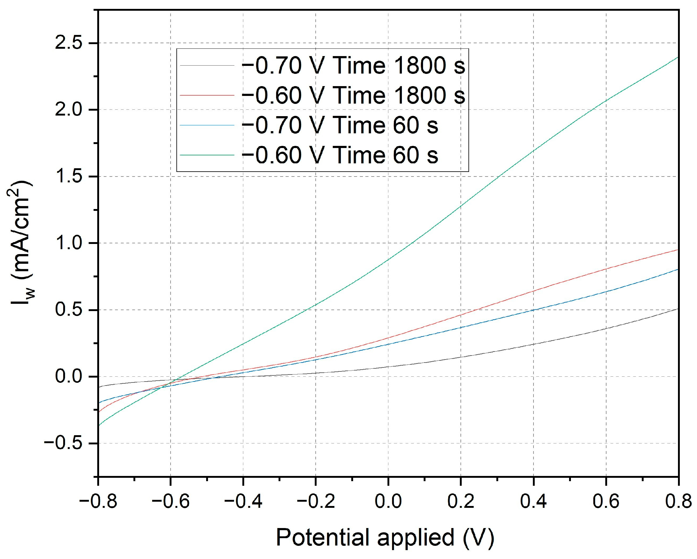
Figure 7 presents linear voltammetry curves for electrodes subjected to different chronoamperometric treatments, providing critical insights into the electrochemical behavior and surface characteristics of the deposited manganese layers. The initial negative currents observed in the curves are attributed to the reduction in oxidized species present on the surface of the deposited manganese or impurities in the medium. The likelihood of water reduction at these potentials with the electrodes used is negligible. As the potential becomes less negative and transitions to positive, the reversal of the current clearly indicates the oxidation of the deposited manganese or the underlying iron. The specific reactions involved are as follows:
Oxidation of Manganese: Mn → Mn2++2e
Oxidation of Iron: Fe (s) → Fe2++2e
Electrodes polarized at −0.70 V for 1800 s (black line): These electrodes exhibit a controlled and gradual transition, reflecting a more stable protective manganese layer. The steady increase in current towards positive values, without significant parasitic reactions, confirms the excellent corrosion resistance provided by the uniform and well-adhered manganese coating.
Electrodes polarized at −0.60 V for 1800 s (red line): A similar pattern is observed with these electrodes, albeit with a smaller initial negative current, indicating a less-oxidized initial layer. This results in slightly reduced corrosion resistance compared to the electrodes treated at −0.70 V. The manganese layer formed under these conditions, while still protective, shows marginally less effectiveness in corrosion prevention.
Electrodes polarized at −0.70 V for 60 s (blue line): The pronounced initial negative current, followed by a rapid increase to positive values, highlights a quick reduction in surface species and subsequent oxidation. This behavior indicates a less uniform deposition process, resulting in a thinner and less consistent manganese layer, which compromises the corrosion protection.
Electrodes polarized at −0.60 V for 60 s (green line): These electrodes demonstrate a rapid rise in current density from slightly negative to positive values. This indicates minimal initial reduction and a swift oxidation process, revealing significant transient and capacitive effects. The manganese layer produced is discontinuous and less protective, offering inadequate corrosion resistance.
The initial negative currents are unequivocally linked to the reduction in oxidized surface species or impurities, while water reduction is not a significant factor at these potentials. As the potential becomes less negative and turns positive, the observed current inversion signifies the oxidation of the deposited manganese or iron substrate. The clearly defined electrochemical reactions highlight the critical role of chronoamperometric parameters in determining the integrity and protective quality of the deposited manganese layer. Electrodes subjected to −0.70 V for longer durations (1800 s) form a more stable and protective manganese layer, whereas shorter times and less negative voltages lead to inferior layers with rapid oxidation transitions, indicating a lower protective quality.
This analysis underscores the necessity of optimizing chronoamperometric conditions to enhance the corrosion resistance of manganese coatings, essential for practical applications.
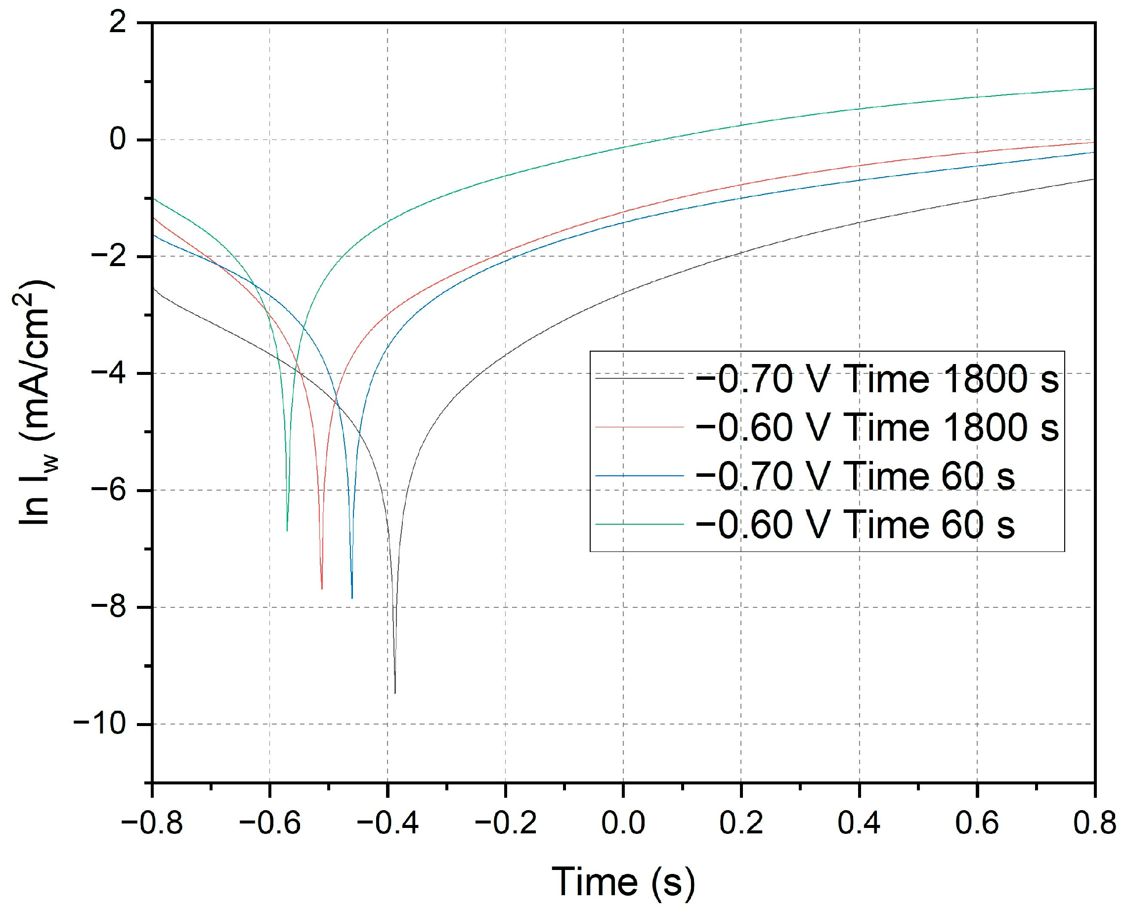
Figure 8 presents crucial data on current density versus time, elucidating the quality of manganese electrodeposition and its impact on the corrosion resistance of annealed steel electrodes. This figure differs from the analysis shown in Figure 4, as the data in Figure 8 were obtained after performing chronoamperometry to deposit manganese on the electrodes. In contrast, Figure 4 represents the cyclic voltammetry analysis conducted before the electrodeposition process to establish the optimal conditions for manganese deposition. The results in Figure 8 clearly demonstrate that the optimal conditions for effective electrodeposition and enhanced corrosion resistance are achieved with a duration of 1800 s at −0.70 V. Following the treatment, the electrodes were immersed in demineralized water, and linear voltammetry tests were conducted over a potential range from −0.8 V to 0.8 V. The resulting graph, depicted on a logarithmic scale of current density, allows for a detailed analysis of Tafel characteristics and corrosion kinetics, providing insights into the efficiency of the coating and its ability to protect against corrosion under different electrochemical conditions.
Electrodes subjected to −0.70 V for 1800 s (black line): These electrodes exhibit a deep minimum followed by a gradual recovery. The linear section of the curve in the cathodic region provides detailed insights into the corrosion rate and kinetic parameters of the reduction process.
Electrodes subjected to −0.60 V for 1800 s (red line): Similar behavior is observed, with a less-pronounced minimum and a smaller slope in the cathodic region, indicating lower reductive activity.
Electrodes subjected to −0.70 V for 60 s (blue line): These display a significant minimum followed by a rapid recovery, suggesting a fast initial reduction and less-controlled subsequent oxidation.
Electrodes subjected to −0.60 V for 60 s (green line): The current density rapidly increases from a minimum to positive values, indicating lower corrosion resistance and less-effective reduction kinetics.
The cathodic and anodic peaks observed in the curves represent the reduction in oxidized species on the deposited manganese, followed by the onset of oxidation processes. The position and depth of these peaks are critical indicators of the efficiency of the reduction process and the quality of the protective manganese coating. The linear regions and Tafel slopes on the logarithmic scale are essential for determining kinetic parameters such as the charge transfer coefficient (β) and the exchange current density (i0), which indicate the ease with which the redox reaction occurs. Electrodes subjected to −0.70 V for 1800 s exhibit steeper Tafel slopes and deeper minima, suggesting higher efficiency in reduction and superior manganese coating quality. In contrast, electrodes subjected to −0.60 V for 60 s show shallower slopes and quicker recovery, indicating lower reduction efficiency and increased corrosion susceptibility.
Scan comparisons reveal that electrodes subjected to −0.70 V for 1800 s exhibit the highest corrosion resistance, with more favorable reduction kinetics and a more uniform manganese coating. In contrast, electrodes subjected to −0.60 V for 60 s demonstrate the lowest corrosion resistance, reflecting less effective reduction kinetics and a less uniform protective layer.
The application of the Butler–Volmer equation to the linear voltammetry data has enabled a detailed assessment of corrosion kinetics and manganese coating quality. Optimal conditions for effective electrodeposition and enhanced corrosion resistance are clearly achieved with 1800 s at −0.70 V, as demonstrated in Table 1. These electrodes exhibit the lowest corrosion current density and corrosion rate, indicating a highly effective protective manganese layer. These findings are critical for developing efficient corrosion protection methods in industrial and research applications, providing clear parameters for optimizing the manganese electrodeposition process.

3.5. Electrochemical Impedance Spectroscopy (EIS) Results

In addition to the Tafel curve analysis, an electrochemical impedance spectroscopy (EIS) study was conducted to evaluate the charge transfer resistance of annealed steel wire in a manganese sulfate monohydrate and KCl solution at the applied voltages during manganese electrodeposition.
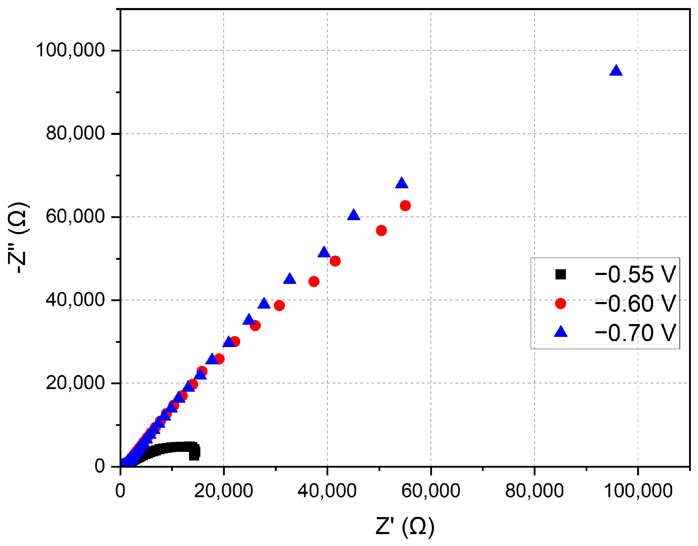
This study assesses the electrochemical properties of annealed steel wire in a solution of manganese sulfate monohydrate and KCl using EIS. The specific potentials analyzed were −0.55 V, −0.6 V, and −0.7 V, selected based on prior studies of manganese electrodeposition. The resulting Nyquist plot represents the impedance of the electrodes at the three applied potentials. In this plot, the Z′ (Ω) axis corresponds to the real part of the impedance, while the −Z″ (Ω) axis represents the imaginary part (see Figure 9).
Semicircular shape: The curves exhibit semicircular arcs, characteristic of systems dominated by charge transfer processes. The semicircular shape indicates that charge transfer resistance (Rct) is the predominant process.
Potential comparison: At −0.55 V (black squares), the impedance is lower compared to −0.6 V (red circles) and −0.7 V (blue triangles), particularly in the high- and mid-frequency regions. The impedance at −0.7 V is greater than at −0.6 V, indicating a higher charge transfer resistance.
Charge transfer resistance: The lower impedance observed at −0.55 V suggests a reduced charge transfer resistance compared to the other potentials. This could imply a less efficient and uniform manganese electrodeposition at this potential.
Double layer capacitance: Variations in impedance may be influenced by changes in the electrochemical double layer capacitance at different potentials. At more negative potentials, the structure of the double layer may be altered, affecting ion distribution and, consequently, the impedance.
Practical implications: Electrodeposition at −0.7 V, which exhibits the highest charge transfer resistance, suggests more favorable conditions for forming a protective manganese layer. The efficiency of electrodeposition must be balanced with coating stability and deposition rate, which may require further analysis using additional electrochemical techniques such as cyclic voltammetry.
An analysis of the Nyquist plot indicates that a potential of −0.70 V results in the highest charge transfer resistance, potentially correlating with more efficient and uniform manganese electrodeposition on annealed steel wire. In contrast, the potential of −0.55 V exhibits lower charge transfer resistance, which may lead to less effective electrodeposition.
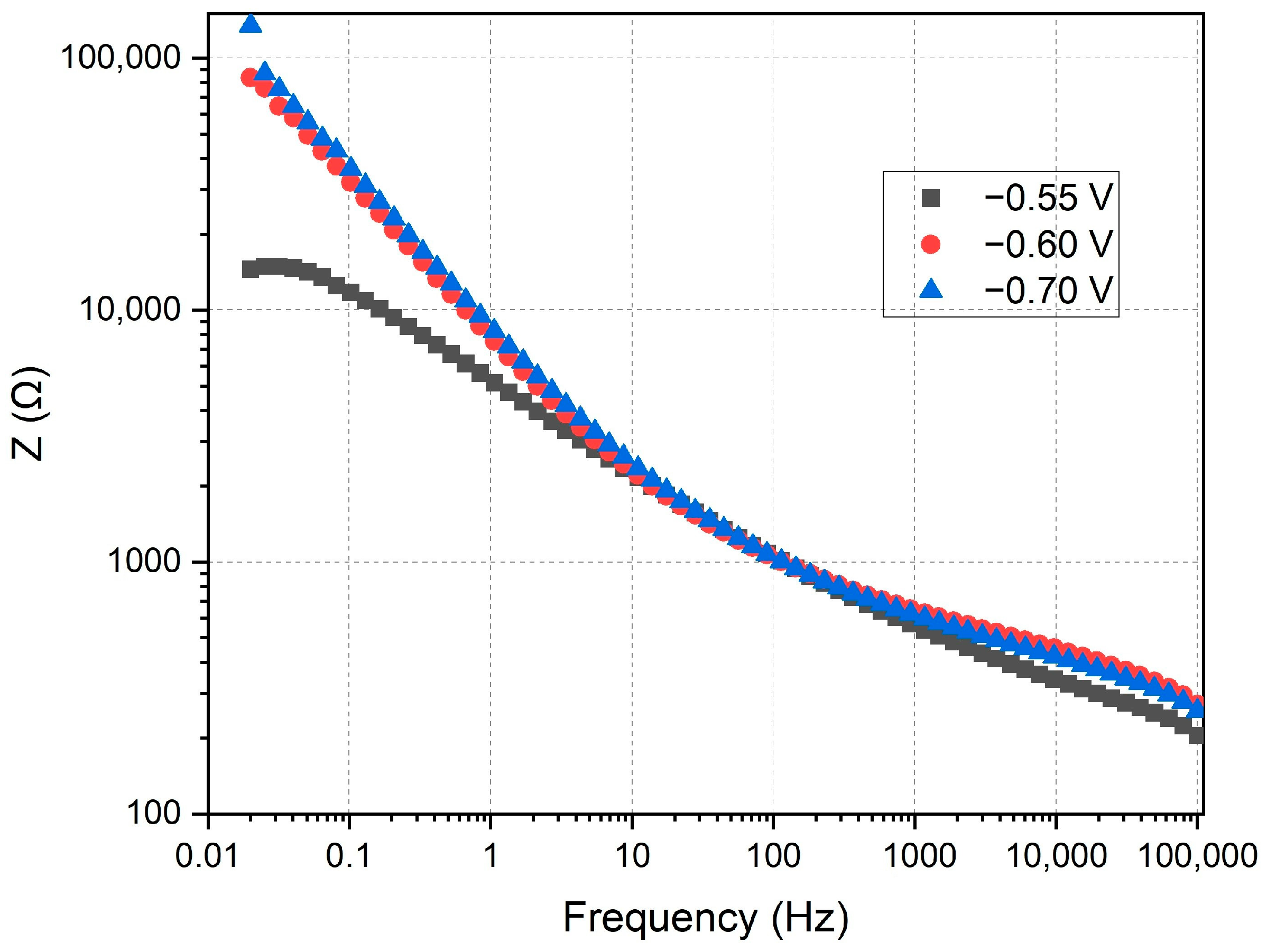
Figure 10 shows the Bode plot depicting impedance as a function of frequency for the three applied potentials. In this plot, the Z (Ω) axis represents the magnitude of the impedance, while the x-axis represents frequency (Hz) on a logarithmic scale.
Impedance behavior: At low frequencies, the impedance is higher, which is typical in electrochemical systems due to the dominance of charge transfer resistance and double layer capacitance. At high frequencies, the impedance decreases, indicating the predominance of electrolyte resistance and inductance of the wiring.
Potential comparison: At −0.55 V (black squares), the impedance is the lowest at low and mid frequencies compared to the other potentials. At −0.7 V (blue triangles), the impedance is the highest across the entire frequency range, indicating a higher charge transfer resistance. At −0.6 V (red circles), the impedance lies between the other two potentials.
Charge transfer resistance: The lowest impedance observed at −0.55 V suggests a lower charge transfer resistance compared to the other potentials, indicating a potentially higher efficiency in electrodeposition at this potential. The higher impedance at −0.7 V indicates a greater charge transfer resistance, suggesting that electrodeposition is less efficient but potentially more uniform and dense.
Double layer capacitance: The difference in impedance at various frequencies also reflects the double layer capacitance. Higher impedance at low frequencies indicates a higher double layer capacitance.
Practical implications: At −0.55 V, the lower charge transfer resistance may result in a faster electrodeposition rate, although the uniformity of the coating could be inferior. At −0.7 V, the higher charge transfer resistance suggests a more controlled and uniform electrodeposition, potentially leading to better coating quality.
An analysis of the Bode plot indicates that a potential of −0.55 V results in the lowest charge transfer resistance, which may lead to faster but less uniform electrodeposition. The potential of −0.7 V shows the highest charge transfer resistance, suggesting more favorable conditions for uniform and controlled manganese electrodeposition. These results are consistent with those observed in the Nyquist plot, reinforcing the hypothesis that a potential of −0.7 V provides the optimal conditions for manganese electrodeposition in terms of coating uniformity and quality.
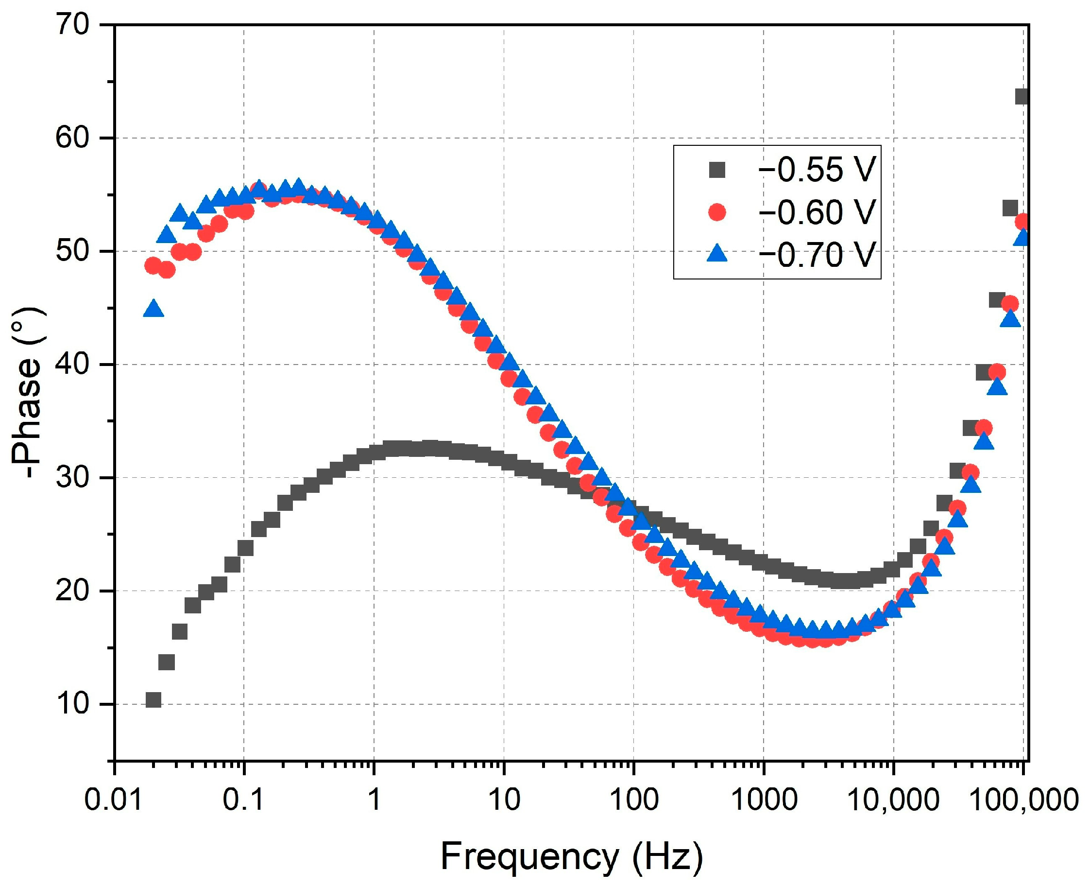
Figure 11 illustrates the phase angle of the impedance as a function of frequency at the three applied potentials. In this plot, the vertical axis represents the phase (degrees), while the horizontal axis denotes frequency (Hz) on a logarithmic scale.
Phase behavior: The three curves exhibit a bell-shaped characteristic, typical of systems dominated by charge transfer and diffusive processes. At low and high frequencies, the phase angle decreases, indicating resistive behavior. In the mid-frequency range, the phase angle increases, reflecting the capacitive contribution of the double layer.
Potential comparison: At −0.55 V (black squares), the phase angle reaches its maximum at lower frequencies compared to −0.6 V (red circles) and −0.7 V (blue triangles). The phase maximum at −0.7 V is slightly higher than at −0.6 V, suggesting a greater capacitive contribution.
Charge transfer resistance: The position of the phase maximum correlates with the characteristic frequency of the system, influenced by the charge transfer resistance and double layer capacitance. The lower frequency at which the phase maximum occurs at −0.55 V suggests a lower charge transfer resistance compared to the other potentials.
Double layer capacitance: The higher phase angle observed at −0.7 V indicates a greater double layer capacitance, potentially related to increased manganese coating coverage. The shape and position of the phase curves indicate differences in the structure and uniformity of the coating formed at different potentials.
Practical implications: At −0.55 V, the lower charge transfer resistance may facilitate faster electrodeposition, although the coating quality may be inferior. Conversely, at −0.7 V, the higher charge transfer resistance and greater double layer capacitance suggest a more controlled and uniform electrodeposition, potentially resulting in superior coating quality.
The phase angle analysis in Figure 11 reveals that a potential of −0.55 V results in a lower charge transfer resistance, potentially leading to faster, albeit less uniform, manganese electrodeposition. The higher phase angle and greater double layer capacitance at −0.7 V imply a more capacitive interface, consistent with a more uniform and dense manganese deposition. This suggests that electrodeposition at −0.7 V not only improves the uniformity and adherence of the manganese layer, but also enhances the protective qualities of the coating by facilitating a more stable and capacitive double layer.
These findings align with the Nyquist and Bode plots, further supporting the conclusion that a potential of −0.7 V offers the optimal conditions for manganese electrodeposition. This potential provides a balanced environment that ensures efficient charge transfer while maintaining a high double layer capacitance, crucial for achieving a consistent and protective manganese layer.
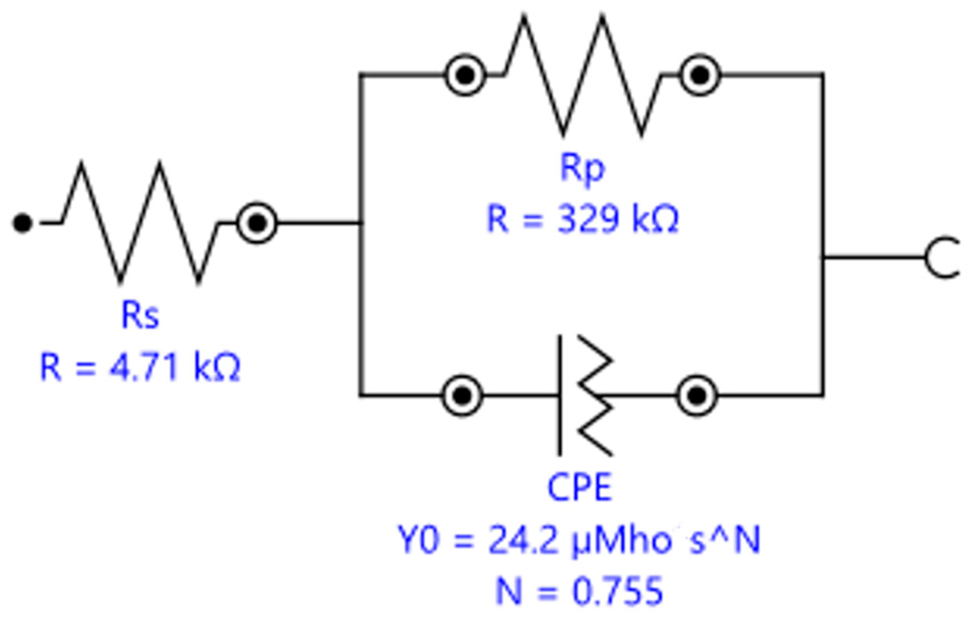
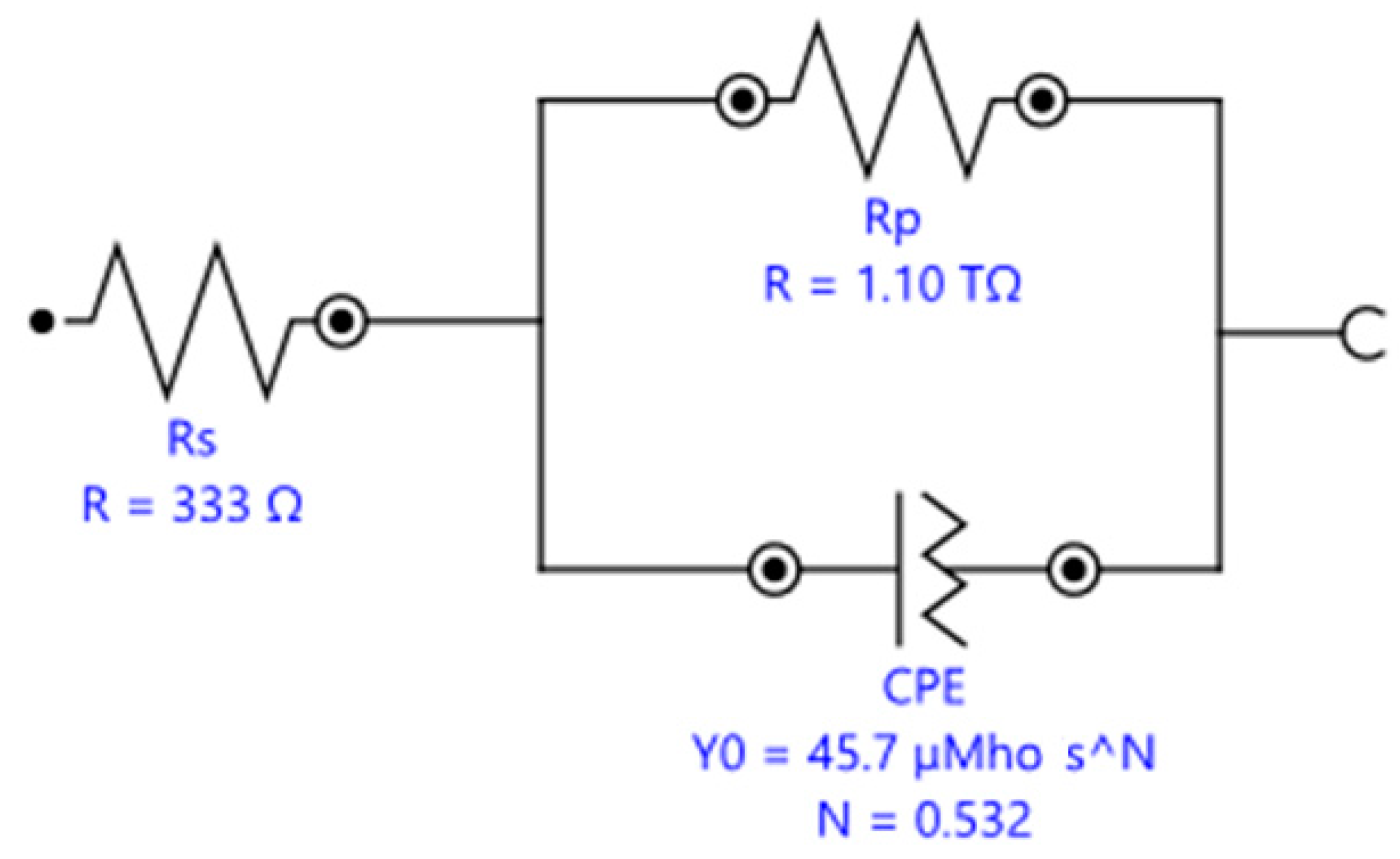
In Figure 12, the equivalent circuit model corresponding to manganese electrodeposition at a potential of −0.7 V is shown. This model reveals a high charge transfer resistance (Rct), suggesting a highly efficient electrodeposition process and the formation of a dense and uniform manganese coating. The use of a constant phase element (CPE) in the model reflects the capacitive complexity of the system, possibly due to the presence of a well-defined electric double layer at the electrode–electrolyte interface. This circuit confirms that, under these conditions, optimal manganese coverage is achieved, significantly enhancing the corrosion resistance of the coated electrode.
Figure 13 presents the equivalent circuit model corresponding to manganese electrodeposition at −0.6 V. The circuit reveals a moderate charge transfer resistance (Rct), indicating that the deposition process, while effective, is not as efficient as at −0.7 V. The presence of a CPE indicates that the electric double layer exhibits variable characteristics, possibly due to surface heterogeneity in the coating. This model suggests that, while the manganese coating formed is functional, its uniformity and protective capacity are inferior compared to the coating obtained at −0.7 V.
Finally, Figure 14 shows the equivalent circuit model corresponding to manganese electrodeposition at a potential of −0.55 V. This model presents a low charge transfer resistance (Rct), suggesting the limited efficiency of the electrodeposition under these conditions. The representation of the CPE suggests a less stable electric double layer, which could be related to a less uniform and less dense manganese coating. As a result, the coating formed at −0.55 V is less effective in terms of corrosion protection, as indicated by the low charge transfer resistance observed in this circuit.
These descriptions provide a detailed technical analysis of each figure, emphasizing the significance of each equivalent circuit model in the context of electrochemistry and corrosion protection.

4. Conclusions

This study delivers a thorough evaluation of the corrosion resistance characteristics of manganese-coated annealed steel wire electrodes, employing advanced chronoamperometric and linear voltametric techniques. The results unequivocally demonstrate that electrodeposition at a potential of −0.70 V for 1800 s produces a highly uniform and effective protective manganese layer, significantly enhancing corrosion resistance by minimizing both corrosion current density and corrosion rate. The findings from electrochemical impedance spectroscopy (EIS) further corroborate this, indicating that the optimized conditions yield the highest charge transfer resistance, a clear indicator of a well-controlled and efficient electrodeposition process.
The use of manganese sulfate monohydrate and potassium chloride in the electrolyte was crucial, with manganese ions forming a dense and uniform protective layer, while chloride ions played a key role in enhancing ionic conductivity and overall system stability. These findings are pivotal for advancing corrosion protection strategies in industrial applications, offering well-defined parameters to optimize the manganese electrodeposition process on annealed steel.
Future research could incorporate SEM analyses to further explore the interplay between microstructure and corrosion resistance, thereby enhancing the practical application and understanding of these findings.

Funding

This research was funded by the Universidad Politécnica de Lázaro Cárdenas.

Institutional Review Board Statement

Not applicable.

Informed Consent Statement

Not applicable.

Data Availability Statement

The original contributions presented in the study are included in the article, further inquiries can be directed to the corresponding author.

Acknowledgments

I sincerely appreciate the Universidad Politécnica de Lázaro Cárdenas for offering me the opportunity and the essential resources to carry out this project.

Conflicts of Interest

The author declares no conflicts of interest.

References

  1. Walter, K.H. Manganese fertilizers. In Manganese in Soils and Plants, Proceedings of the International Symposium on ‘Manganese in Soils and Plants’ Held at the Waite Agricultural Research Institute, The University of Adelaide, Glen Osmond, South Australia, 22–26 August 1988 as an Australian Bicentennial Event; Springer: Dordrecht, The Netherlands, 1988; pp. 225–241. [Google Scholar]
  2. Zhang, Y.; Liu, Z.; Wang, Y.; Zhai, Y.; Cui, C.; Zhang, Q.; Du, Z.; Yuan, Y.; Wang, X. Study on the role of chromium addition on sliding wear and corrosion resistance of high-manganese steel coating fabricated by wire arc additive manufacturing. Wear 2024, 540, 205242. [Google Scholar] [CrossRef]
  3. Machado, P.C.; Pereira, J.I.; Sinatora, A. Abrasion wear of austenitic manganese steels via jaw crusher test. Wear 2021, 476, 203726. [Google Scholar] [CrossRef]
  4. Labena, A.; Hegazy, M.A.; Kamel, W.M.; Elkelish, A.; Hozzein, W.N. Enhancement of A Cationic Surfactant by Capping Nanoparticles: Synthesis, Characterization and Multiple Applications. Molecules 2020, 25, 2007. [Google Scholar] [CrossRef] [PubMed]
  5. Saji, V.S. Corrosion and materials degradation in electrochemical energy storage and conversion devices. ChemElectroChem 2023, 10, e202300136. [Google Scholar] [CrossRef]
  6. Jiang, C.; Wu, Y.F.; Dai, M.J. Degradation of steel-to-concrete bond due to corrosion. Constr. Build. Mater. 2018, 158, 1073–1080. [Google Scholar] [CrossRef]
  7. Wasim, M.; Li, C.Q.; Mahmoodian, M.; Robert, D. Mechanical and microstructural evaluation of corrosion and hydro6gen-induced degradation of steel. J. Mater. Civ. Eng. 2018, 31, 04018349. [Google Scholar] [CrossRef]
  8. Perez, N. Electrochemical Corrosion. In Electrochemistry and Corrosion Science; Springer: Cham, Switzerland, 2016; pp. 1–23. [Google Scholar]
  9. Bender, R.; Féron, D.; Mills, D.; Ritter, S.; Bäßler, R.; Bettge, D.; De Graeve, I.; Dugstad, A.; Grassini, S.; Hack, T.; et al. Corrosion challenges towards a sustainable society. Mater. Corros. 2022, 73, 1730–1751. [Google Scholar] [CrossRef]
  10. Di Sarno, L.; Majidian, A.; Karagiannakis, G. The effect of atmospheric corrosion on steel structures: A state-of-the-art and case-study. Buildings 2021, 11, 571. [Google Scholar] [CrossRef]
  11. Loukili, H.; Azzaoui, K.; Bouyanzer, A.; Kertit, S.; Hammouti, B. Corrosion Inhibition using Green Inhibitors: An Overview. Maghrebian J. Pure Appl. Sci. 2022, 8, 82–93. [Google Scholar] [CrossRef]
  12. Koch, G. Cost of corrosion. In Trends in Oil and Gas Corrosion Research and Technologies; Woodhead Publishing: Sawston, UK, 2017; pp. 3–30. [Google Scholar] [CrossRef]
  13. Sun, Y. Surface Engineering & Coating Technologies for Corrosion and Tribocorrosion Resistance. Materials 2023, 16, 4863. [Google Scholar] [CrossRef]
  14. Volkov, A.I.; Efremova, A.O.; Tolstopyatova, E.G.; Kondratiev, V.V. Synthesis and Electrochemical Properties of Manganese Dioxide as Cathode Material for Aqueous Zinc-Ion Batteries. Russ. J. Appl. Chem. 2019, 21, 154–161. [Google Scholar] [CrossRef]
  15. Lu, J.; Dreisinger, D.; Glück, T. Manganese electrodeposition—A literature review. Hydrometallurgy 2014, 141, 105–116. [Google Scholar] [CrossRef]
  16. Kushwaha, A.; Aslam, M. ZnS shielded ZnO nanowire photoanodes for efficient water splitting. Electrochim. Acta 2014, 130, 222–231. [Google Scholar] [CrossRef]
  17. Skompska, M.; Zarębska, K. Electrodeposition of ZnO nanorod arrays on transparent conducting substrates—A review. Electrochim. Acta 2014, 127, 467–488. [Google Scholar] [CrossRef]
  18. Ruiz-Ocampo, F.D.; Zapien-Rodríguez, J.M.; Burgara-Montero, O.; Escoto-Sotelo, E.A.; Núñez-Pérez, F.A.; Ballesteros-Pacheco, J.C. Electrodeposition of Nanostructured ZnO Photoanodes for Their Application in the Oxygen Evolution Reaction. Int. J. Electrochem. Sci. 2017, 12, 4898–4914. [Google Scholar] [CrossRef]
  19. Cabral-Miramontes, J.A.; Bastidas, D.M.; Baltazar, M.A.; Zambrano-Robledo, P.; Bastidas, J.M.; Almeraya-Calderón, F.M.; Gaona-Tiburcio, C. Corrosion behavior of Zn-TiO2 and Zn-ZnO electrodeposited coatings in 3.5% NaCl solution. Int. J. Electrochem. Sci. 2019, 14, 4226–4239. [Google Scholar] [CrossRef]
  20. Falcón, J.M.; Aoki, I.V. Electrodeposition of ZnCo alloy coatings on carbon steel and their corrosion resistance. Surf. Coat. Technol. 2024, 481, 130603. [Google Scholar] [CrossRef]
  21. Núñez-Perez, F.A. Electrochemical analysis of the corrosion resistance of annealed steel with nickel coating in marine environment simulations: Chronoamperometric and voltametric study. Ibero-Am. J. Eng. Technol. Stud. 2024, 4, 62–70. [Google Scholar] [CrossRef]
  22. Mukherjee, J.; Adalder, A.; Mukherjee, N.; Ghorai, U.K. Solvothermal synthesis of α–CuPc nanostructures for electrochemical nitrogen fixation under ambient conditions. Catal. Today 2023, 423, 113905. [Google Scholar] [CrossRef]
  23. Dawkins, R.C.; Wen, D.; Hart, J.N.; Vepsäläinen, M. A screen-printed Ag/AgCl reference electrode with long-term stability for electroanalytical applications. Electrochim. Acta 2021, 393, 139043. [Google Scholar] [CrossRef]
  24. Nigde, M.; Agir, I.; Yıldırım, R.; Isildak, I. Development and comparison of various rod-shaped mini-reference electrode compositions based on Ag/AgCl for potentiometric applications. Analyst 2022, 147, 516–526. [Google Scholar] [CrossRef] [PubMed]
  25. Cui, Z.; Sheng, W. Thoughts about choosing a proper counter electrode. ACS Catal. 2023, 13, 2534–2541. [Google Scholar] [CrossRef]
  26. Elsehamy, M.Y. Effect of Demineralized Water on Carbon Steel and Stainless Steel. Bachelor’s Thesis, German University in Cairo, Cairo, Egypt, 2016; pp. 62–63. [Google Scholar]
  27. Abdu, M.T.; Khalifa, W.; Abdelrahman, M.S. Microbiologically influenced corrosion of austenitic stainless-steel TP-316LN under demineralized water. J. Fail. Anal. Prev. 2022, 22, 1816–1825. [Google Scholar] [CrossRef]
  28. Yang, J.; Papaderakis, A.A.; Roh, J.S.; Keerthi, A.; Adams, R.W.; Bissett, M.A.; Radha, B.; Dryfe, R.A. Measuring the Capacitance of Carbon in Ionic Liquids: From Graphite to Graphene. J. Phys. Chem. C 2024, 128, 3674–3684. [Google Scholar] [CrossRef] [PubMed]
Figure 1. Open Circuit Potential (OCP) voltage stability over time for manganese-coated steel electrodes.
Appliedchem 04 00023 g001
Figure 2. Cyclic voltammetry curves for manganese-coated steel electrodes.
Appliedchem 04 00023 g002
Figure 3. Detail of potential range for Mn2+ to Mn reduction reactions.
Appliedchem 04 00023 g003
Figure 4. Cyclic voltammetry analysis with logarithmic transformation.
Appliedchem 04 00023 g004
Figure 5. Chronoamperometry at −0.55 V, −0.60 V, and −0.70 V.
Appliedchem 04 00023 g005
Figure 6. Chronoamperometry at −0.60 V and −0.70 V.
Appliedchem 04 00023 g006
Figure 7. Linear voltammetry curves under different chronoamperometric conditions.
Appliedchem 04 00023 g007
Figure 8. Tafel plots obtained via linear voltammetry (ln(current density) vs. potential) for annealed steel electrodes under different chronoamperometric conditions.
Appliedchem 04 00023 g008
Figure 9. Nyquist plot for different potentials.
Appliedchem 04 00023 g009
Figure 10. Bode plot for different potentials.
Appliedchem 04 00023 g010
Figure 11. Phase plot for different potentials.
Appliedchem 04 00023 g011
Figure 12. Equivalent circuit model for manganese electrodeposition at −0.7 V showing high charge transfer resistance (Rct).
Appliedchem 04 00023 g012
Figure 13. Equivalent circuit model for manganese electrodeposition at −0.6 V indicating moderate charge transfer resistance (Rct).
Appliedchem 04 00023 g013
Figure 14. Equivalent circuit model for manganese electrodeposition at −0.55 V with low charge transfer resistance (Rct).
Appliedchem 04 00023 g014
Table 1. Corrosion rate calculations for manganese-electrodeposited samples.
Chronoamperometric Time (s)Chronoamperometric Voltage (V)Ecorr, obs (V)Jcorr (A/cm2)Icorr (A)Corrosion Rate (mm/Year)
60−0.6−0.569694.41 × 10−48.86 × 10−65.1253
1800−0.6−0.512835.61 × 10−55.61 × 10−50.65205
60−0.7−0.461479.94 × 10−52.00 × 10−61.1549
1800−0.7−0.38811.21 × 10−52.43 × 10−70.14023
Disclaimer/Publisher’s Note: The statements, opinions and data contained in all publications are solely those of the individual author(s) and contributor(s) and not of MDPI and/or the editor(s). MDPI and/or the editor(s) disclaim responsibility for any injury to people or property resulting from any ideas, methods, instructions or products referred to in the content.

