Article

An Investigation of Various Controller Designs for Multi-Link Robotic System (Robogymnast)

1
Wolfson Centre for Magnetics, School of Engineering, Cardiff University, Cardiff CF24 3AA, UK
2
Electrical and Electronic Department, Azahra Higher Institution of Sciences and Technology, Azahra, Libya
3
Faculty of Engineering, University of Zawia, Zawia 16418, Libya
*
Author to whom correspondence should be addressed.
Knowledge 2022, 2(3), 465-486; https://doi.org/10.3390/knowledge2030028
Submission received: 30 July 2022 / Revised: 23 August 2022 / Accepted: 26 August 2022 / Published: 6 September 2022

Abstract

:
An approach to controlling the three-link Robogymnast robotic gymnast and assessing stability is proposed and examined. In the study, a conventionally configured linear quadratic regulator is applied and compared with a fuzzy logic linear quadratic regulator hybrid approach for stabilising the Robogymnast. The Robogymnast is designed to replicate the movement of a human as they hang with both hands holding the high bar and then work to wing up into a handstand, still gripping the bar. The system, therefore has a securely attached link between the hand element and the ‘high bar’, which is mounted on ball bearings and can rotate freely. Moreover, in the study, a mathematical model for the system is linearised, investigating the means of determining the state space in the system by applying Lagrange’s equation. The fuzzy logic linear quadratic regulator controller is used to identify how far the system responses stabilise when it is implemented. This paper investigates factors affecting the control of swing-up in the underactuated three-link Robogymnast. Moreover, a system simulation using MATLAB Simulink is conducted to show the impact of factors including overshoot, rising, and settling time. The principal objective of the study lies in investigating how a linear quadratic regulator or fuzzy logic controller with a linear quadratic regulator (FLQR) can be applied to the Robogymnast, and to assess system behaviour under five scenarios, namely the original value, this value plus or minus ±25%, and plus or minus ±50%. In order to further assess the performance of the controllers used, a comparison is made between the outcomes found here and findings in the recent literature with fuzzy linear quadratic regulator controllers.

1. Introduction

Non-linear control theory research frequently uses Inverted Pendulum Systems (IPSs) [1] as an example of unstable, underactuated systems [2]. Continuing work to develop novel control technology reflects advances made across a range of areas within the realm of science and technology. Effective measurement of a control system can be achieved through the design and application of a controller with a specific system, to monitor its activities. This paper presents an investigation of swing-up movement in the Robogymnast as a three-link, non-linear robotic system [3]. The Robogymnast exemplifies complex mechanical systems with more than one link and with underactuation and is therefore a suitable case study for evaluating and comparing different types of control system [4]. The underactuated system presents control challenges because of the lack of ability to linearise full-state feedback about a specific point of equilibrium in many of these systems, as well as potentially not being small-time local controllable (STLC) [5]. Various research has been conducted to address this issue in the control engineering and robotics literature [6]. An inverted pendulum-derived system is a frequent choice with which to demonstrate an underactuated mechanism. This type of system has a component attached to a set point from which it swings freely, and gravity acts upon this component. Motion control investigations frequently employ pendulum systems, which enable hybrid and chaotic systems to be demonstrated [7,8,9].
The triple-inverted pendulum mechanism is of interest to the robotics field because it is analogous to the way in which human bodies are structured and achieve balance. The Acrobat robotic system, named for its similarities to acrobatic movements, is an unstable and underactuated system based on an inverted pendulum, and is therefore an appropriate model for studies of non-linear controls in theory and in implementation [6,10]. The Acrobat was used with a designed intelligent control system to allow the robot to balance, with the design combining a conventional controller with fuzzy and adaptive-fuzzy controllers, to achieve swing and catch actions and to balance in inversion [9]. State variable feedback was utilised here, as well as LQR and proportional-integral-derivative.
In brief, the novelty of this work is to apply and compare a different controller on a multi-link robotic system, to analyse and review the stability and robustness of both proposed controllers’ performance, and then investigate the performance of the normal conventional LQR compared with the hybrid fuzzy LQR successfully implemented in various cases by adding and subtracting ±25% and ±50% to the system.
In this work, the paper is organised as follows. Section 2 describes the relative study and examination of previous research; Section 3 contains two parts, which are, firstly, an overview of the system, as well as the mathematical model of the Robogymnast analysed; fourthly, the control design of LQR and FLQR are presented. Moreover, Section 5 presents the robustness investigation for the proposed controller, followed by the results and comparison of all suggested cases. Lastly, we summarize the investigation and future outcomes of the system are mentioned.

2. Literature Review

Various studies [11,12,13,14,15,16] examine autonomous upswing for a three-link robot with a single non-actuated and two actuated joints. The current study’s contribution to this area involves assessing the use of an LQR controller and a fuzzy LQR controller when applied with the Robogymnast: a robot with multiple links and a pendulum action. The robotic system used is described in Section 2, and a discussion of the system’s mathematical model is also given. Section 3 considers the upswing control problem, while Section 4 describes the application of each controller to the Robogymnast and details the responses recorded. Then, Section 5 discusses the simulation and its findings, while Section 6 provides the study’s conclusions.
Earlier studies [17,18,19] demonstrate LQR as an active method for designing controllers for the performance of complex systems. In addition, state feedback control (SFC) operates based on where the system’s poles are located, which depends upon state variables and K as the gain matrix. Using SFC, the location of closed-loop system poles can be freely set, while, when using output feedback controls, poles are located at predefined points. The controller used combines LQR as an optimal control method with fuzzy approaches to control [20]. A fuzzy logic control system is rule-based, and depends centrally on a Fuzzy Control Rule (FCR) set connected through fuzzy implication as well as the compositional rule of inference [21]. FPD controllers use a combination of a PD and fuzzy logic controller [22], and the choice of this controller type to bring stability to the Robogymnast was made here because the system is non-linearly unstable, and FDP can address this issue and stabilise the robot [23]. The PD controller is a feedback controller whose output is a control variable, generally derived from error (e) when a comparison is made of a process variable’s (PV’s) reference value as set by the user against the measured value. The error is then used by the different elements within the controller to choose a particular action [18]. Employed-feedback proportional integral derivative (PID) controllers are widely used for co-ordinating industrial controls, as well as in any context where controls must be modulated on an ongoing basis. A PID controller works by analysing and measuring errors using the difference between the target set-point (SP) and the measured value of the PV, making real-time modifications based on integral (I), derivative (D) and proportional (P) terms. In practice, this results in automated, accurate responses in altering a control function. Through increasing system capabilities, the PID algorithm used by the controller brings the output measured into line with desired inputs while minimising deferral error [24]. Modelling and simulation of both PID and LQR controllers for use to control the Robogymnast took place in MATLAB/Simulink. Within this, a PID controller was developed and implemented with the robotic pendulum system and its performance compared to that of the conventional LQR controller [25]. The initial stage involved creating a mathematical model of the robotic system and then modelling a robotics manipulation drive with PI [19].

3. Materials and Methods

3.1. System Description

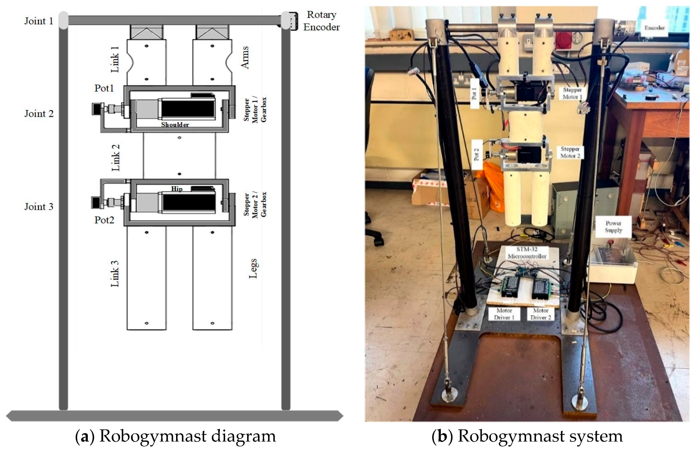
The basis of the design for the three-link robotic system used in this study comes from an established movement in gymnastics in which an individual hanging from a high bar uses free rotation to swing up and over the top. Figure 1a provides a block diagram representing the system (Figure 1b) in its principal components. The first link is analogous to the arms of the gymnast, with no wrist or elbow jointing; Link 2 combines the gymnast’s trunk, neck, and head into one unified part, and Link 3 connects the legs and feet, with no jointing for the knees and ankles. The non-actuated, passive joint (Joint 1) in the system is analogous to the athlete’s hands, and the active second and third joints relate to the shoulder and then the hip joints in a human [26,27]. As shown in Figure 1a,b’s representation, the system is operated using two stepper motors connected to a stepper driver, which allows the system to move smoothly. In addition, the STM32F Microcontroller (ST, Italy) is used for programming of the control system, using the language C++ for converting commands passed from the PC-based control system and the robotic system. A sensor is also assigned to each of the links, with Link 1 being connected to a rotary encoder, while potentiometers 2 and 3 were connected to Links 2 and 3, respectively, and the sensors monitored the absolute angles at each position [17].

3.2. Mathematical Model

This subsection provides the mathematical modelling of the designed controller, in relation to the Robogymnast as shown in Figure 1a,b. Lagrange equations were utilised to generate system motion equations [3].
Modelling of the robot while vertical used linear, continuous-time, state-space approaches, applied using multiple tools in MATLAB and additional researcher-generated M-files. In Table 1, names and values are provided for each parameter. Matrices to model state space are termed A, B, C and D. The anti-swing controller’s purpose is to stabilise pendulum links in vertical downward alignment with minimal vibration. Link state as representing the point of stable is as follows: θ1 = θ2 = θ3 = 0. The equations’ state space for the robotic system is given by
ẋ = Ax + Bu
y = Cx
x is the state vector of the system, y is the output vector. The numerical model of the Robogymnast was calculated by MATLAB/Toolbox to obtain A, B and C, whereas
A = [ 0 3 I 3 A 22 A 22 ]
where
0 3 = [ 0 0 0 0 0 0 0 0 0 ]        I 3 = [ 1 0 0 0 1 0 0 0 1 ]
A 21 = [ 0 2.8625 0.0657 0 29.2751 15.8236 0 57.5286 247.5924 ]
A 22 = [ 0.0286 0.0083 0.0284 0.0391 0.1957 1.2358 0.0589 1.0485 18.0527 ]
State-space matrices for Robogymnast (A, B, C and D) are shown below:
A = [ 0 0 0 1 0 0 0 0 0 0 1 0 0 0 0 0 0 1 0 2.6825 0.0657 0.0286 0.0083 0.0284 0 29.2751 15.8236 0.0391 0.1957 1.2358 0 57.5286 247.5924 0.0589 1.4085 18.0527 ]
B = [ 0 0 0 1.0314 1.6582 2.4837 ]       C = [ 1 0 0 0 0 0 0 1 0 0 0 0 0 0 1 0 0 0 0 0 0 1 0 0 0 0 0 0 1 0 0 0 0 0 0 1 ]
The Robogymnast’s discrete-time modelling was performed through discretisation of Equations (1) and (2), which were then applied in the MATLAB command window for the implementation of mathematical model matrices in the simulation to determine outcomes. This was carried out through the MATLAB commands described in which
sys = ss [A, B, C, D]
ss2tf: h = tf [sys]
Table 1. Robogymnast parameters [18].
ParametersSymbol Mean Values
Length of the first link L 1 0.16 m
Length of the second link L 2 0.18 m
Length of the third link L 3 0.24 m
Weight of the first link m 1 1.2 kg
Weight of the second link m 2 1.2 kg
Weight of the third link m 3 0.5 kg
Angles between poles 1, 2, and 3 θ θ 1 , θ 2 , θ 3 (rad)
Initial values of the anglesq1, q2, q30 (rad)
Gravityg 9.81   m / s 2

4. Control Design

This section discusses the control methods applied within the study in detail. This begins with a discussion of the function of the LQR control system and how this was implemented for the parameters of the robotic system, with a similar discussion following for the FLQR control system.

4.1. LQR

LQR provides an active method for a controller when considering performance in a complex system [28]. In addition, SFC uses the system’s pole sites, as set using state variables and gain matrix K, permitting the free location of poles in closed-loop systems as required, while fixed locations are used in output feedback control methods [29]. In this approach, SFC is used for implementation of the state variables, which generate feedback. Each feedback component is then multiplied using the state feedback gain matrix and compared to reference input values [24]. Gain matrix calculations are the main application of state feedback control [30]. To achieve this, an LQR controller is commonly used, and for the greatest effectiveness with this type of controller, among the parameters of the K matrix parameters should be the cost function (J) for stat optimisation, x(t), and u(t) as the systems control signal [31]. Here, where Q is the constant symmetry positive, and matrix R is constant, optimal control is written as follows.
The algebraic Riccati equation is used to calculate K and P values.
u (t) = −K × (t)
J = 1 2 0 ( x t   Q x + u t   R u )   dt
U = R 1   B T   P X = K X
The algebraic Riccati equation is used to calculate K and P values.
A T + P A P B R 1 B T P + Q = 0
K = R 1 B T P = [ K 1     K 2     K 3     .   K 6 ] .  
K = [0.2581 22.789 −507.886 0.940 −12.250 −19.480]
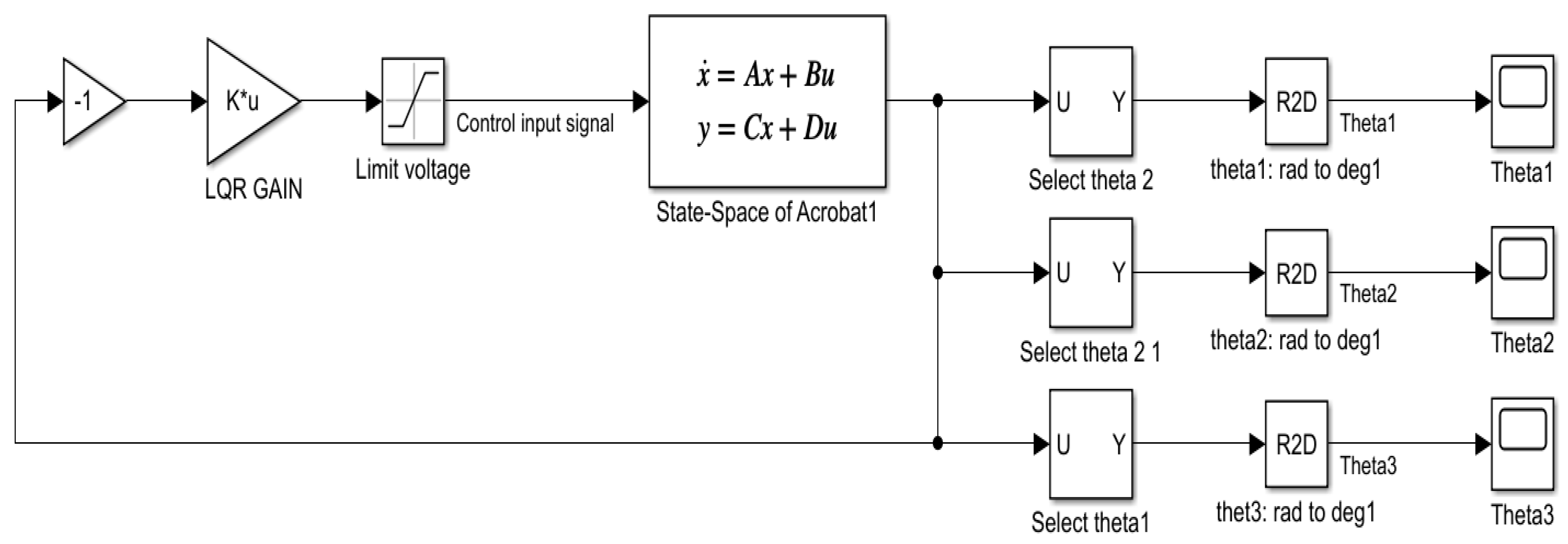
In this work, LQR is implemented by MATLAB/Simulink as shown in Figure 2.

4.2. FLQR

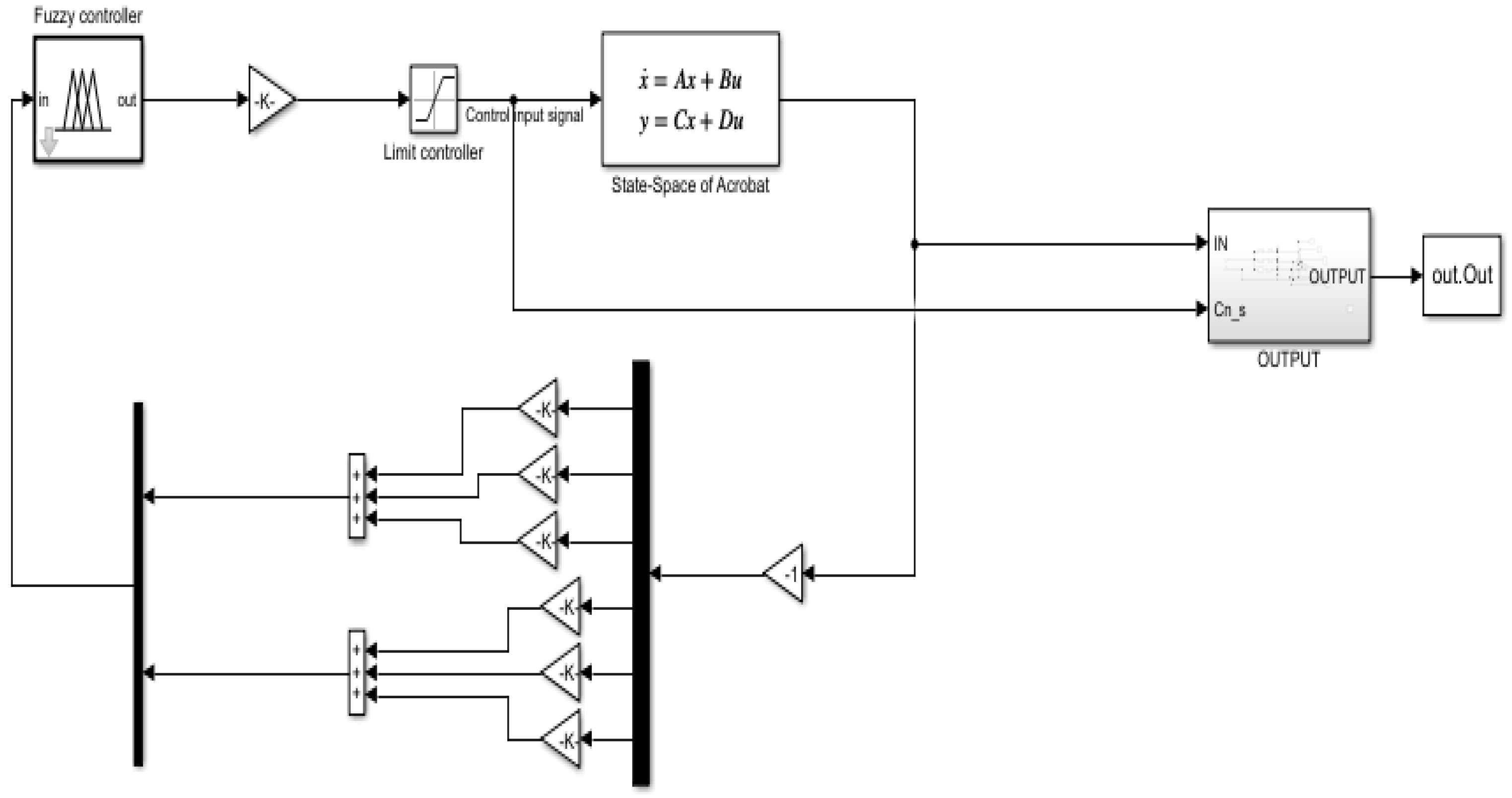
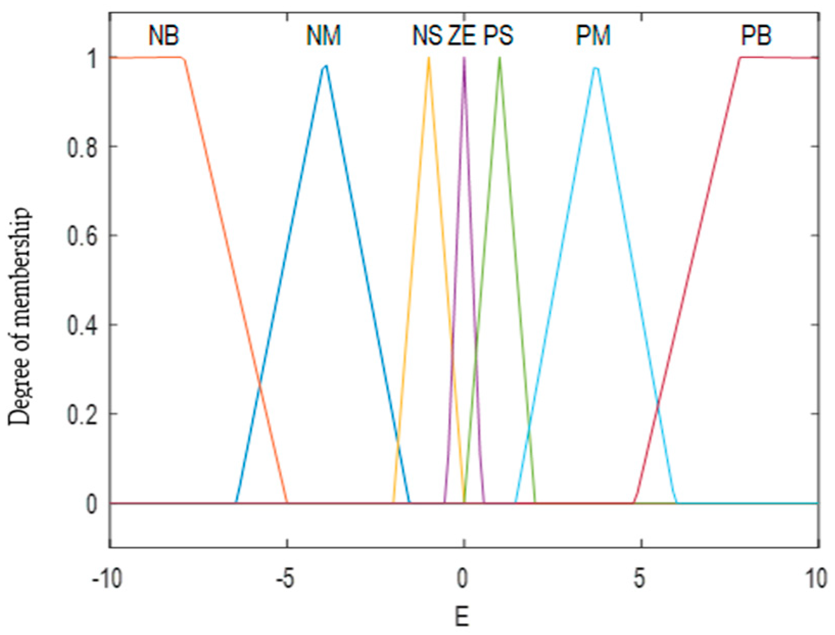
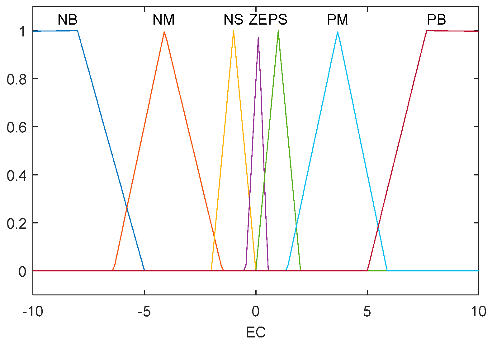
The resulting controller offers a combination of LQR optimised control and fuzzy logic-based control (FLC) [20]. FLC operates on a rule-based premise by applying an FCR set linked through fuzzy implication and the compositional rule of inference [21,32]. The design procedure followed to produce the FLC is given in this subsection. Structuring of the FLC is as illustrated in Figure 3, with the FLC functioning as complementary to the main controller in changing conditions [33]. There are varied tool and system applications for fuzzy logic in the manufacturing sector, with FLCs enabling more intelligent technologies [34]. The Mamdani approach was used to develop the fuzzy model, and this enabled modifications of closed-loop controller feedback gains. Transformation of the input control signal parameters error (E) and change of error (EC), and of the output U, generated variables based on language: NB = negative big; NM = negative medium; NM = negative small; Z = zero; PS = positive small; PM = positive medium; and PB = positive big. Graphic inference of input and output variables was performed via triangular membership functions. Figure 4 and Figure 5 show the inputs E and EC, and the output variable range is given in Figure 6 [18]. The fuzzy rules that apply to the controller are given in Table 2, Table 3 presents rules of the FL controller, and a sample Simulink implementation of the Robogymnast and FLQR controller is provided in Figure 6.
MATLAB Simulink was used as a simulation environment for determining system responses, with the findings being used in designing the control systems put forward here. A performance evaluation of closed-loop systems operation was performed, related to the step response with the controller. Both the linear LQR and non-linear FLQR controller were modelled and their use in stabilising the robotic system simulated in MATLAB Simulink [17]. Outcomes for output responses demonstrated enhanced overshoot and rise times as well as other benefits when the FLQR controller was applied, considering the system’s step response (see Figure 6).
Table 2. Fuzzy rules linguistic variables.
Symbol Linguistic Variable
NBNegative Big
NmNegative Medium
NSNegative Small
ZZero
PSPositive Small
PMPositive Medium
PBPositive Big
Figure 3. Membership function of fuzzy input.
Knowledge 02 00028 g003
Figure 4. Membership (error of change) function of fuzzy input (error).
Knowledge 02 00028 g004
Figure 5. Membership function of fuzzy output variable (u).
Knowledge 02 00028 g005
Table 3. Rules of FL controller [18].
Error Change in Error
NBNMNSZPSPMPB
NBNBNBNBNMNMNSZ
NMNBNBNBNMNSZPS
NSNBNMNMNSZPSPM
ZNMNMNSZPSPMPB
PSNMNSZPSPMPMPB
PMNSZPSPMPMPBPB
PBZPSPMPMPBPBPB
Figure 6. FLQR Simulink.
Knowledge 02 00028 g006

4.3. Robustness Investigation for the Proposed Controller

In order to determine whether the proposed controller is robust, this section analyses parametric uncertainty within the three-link system and the impacts of this on stabilising the system, in a multi-scenario approach. Various possible parametric system conditions are explored, and these results are listed in Section 5. Primarily, the testbed parameters were each altered in isolation, before altering multiple parameters at one time, increasing, and then decreasing them by 25% and 50% from the baseline.
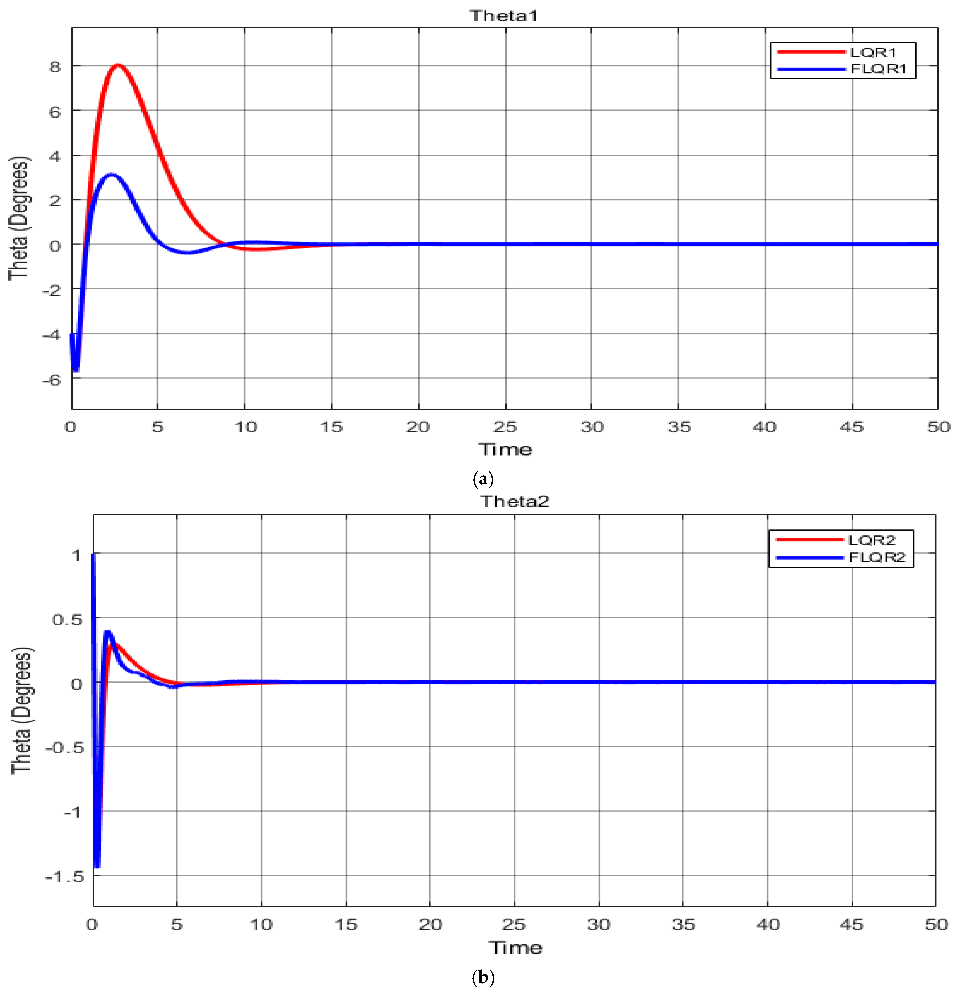
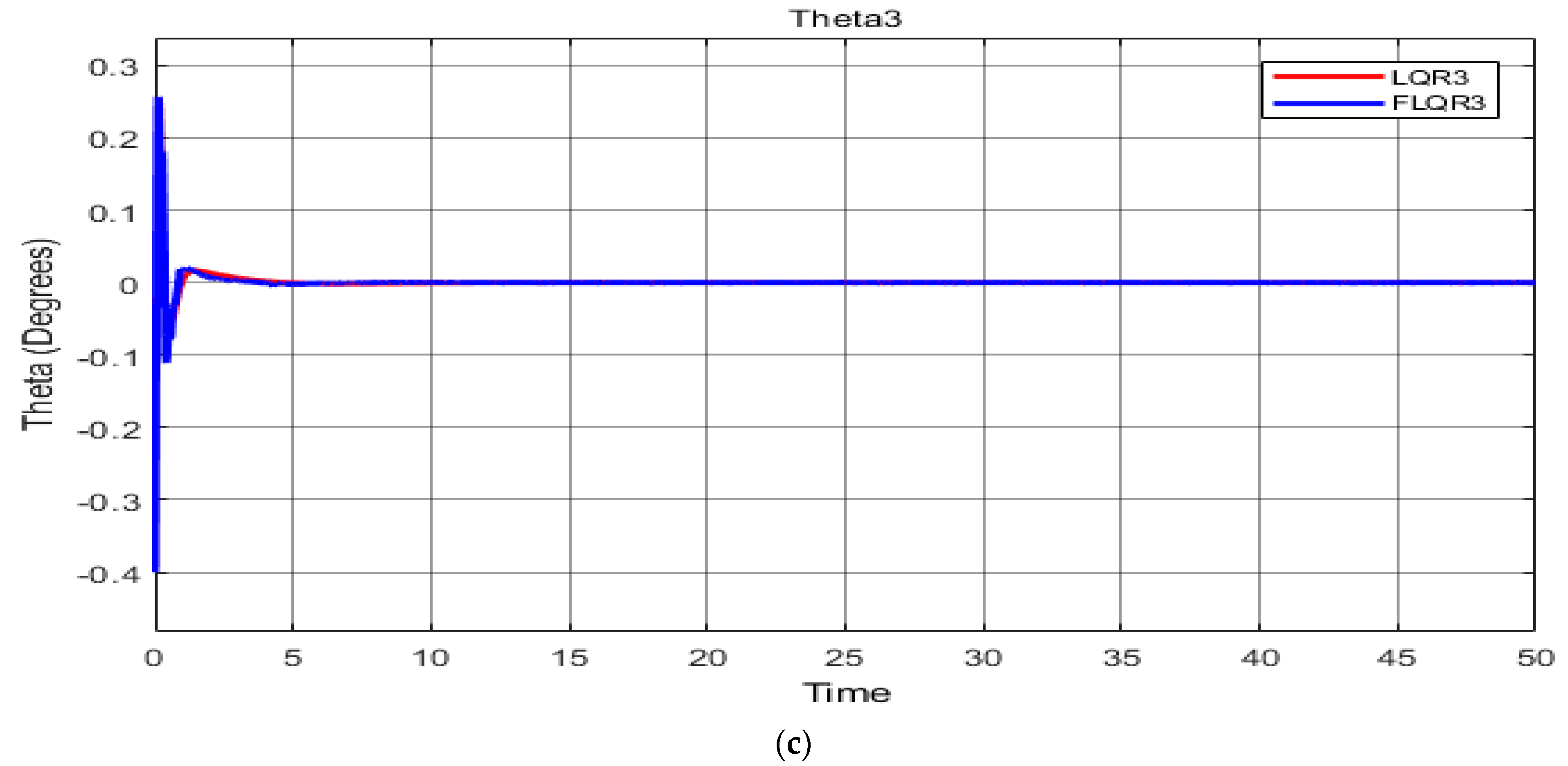
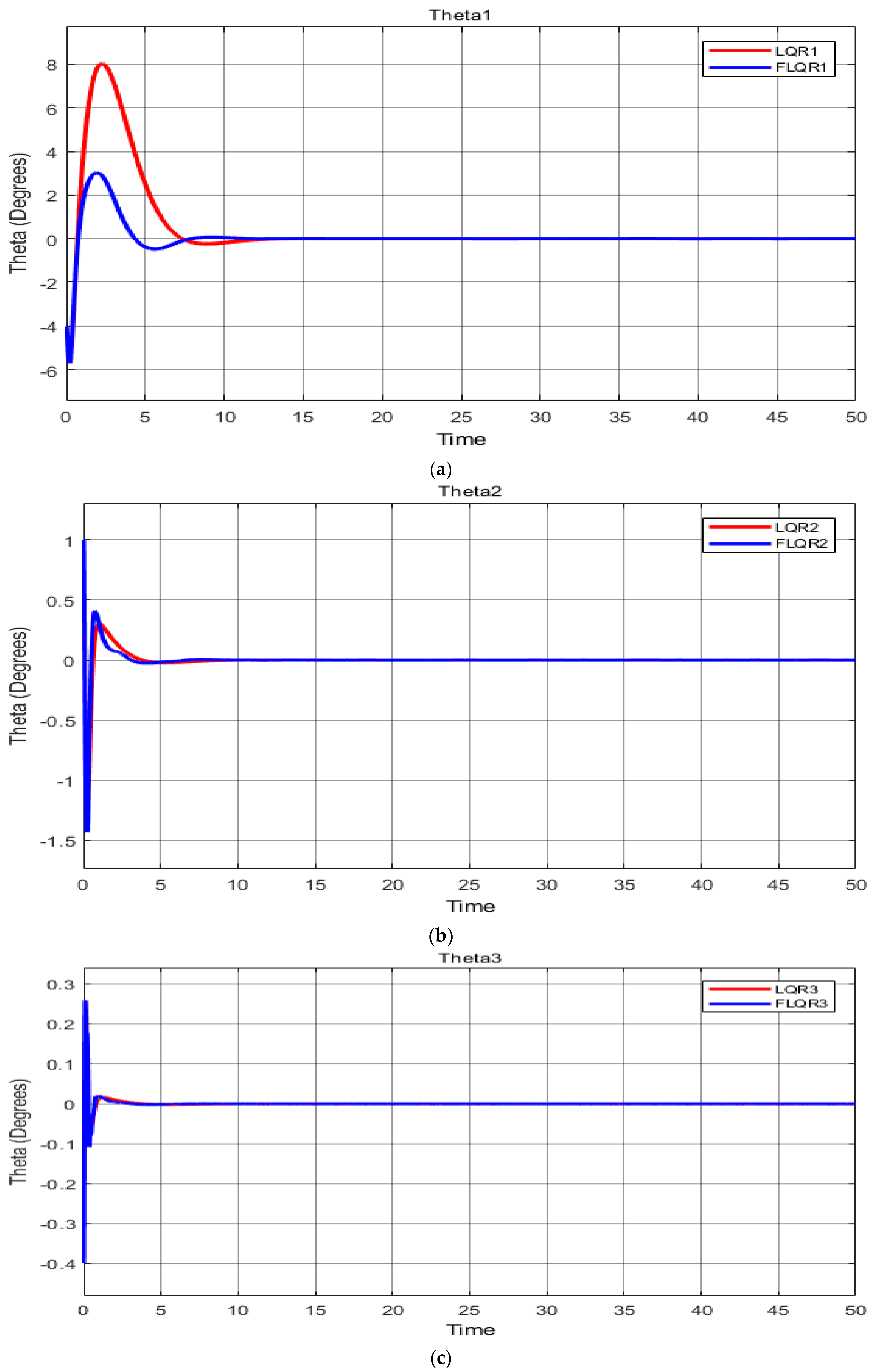
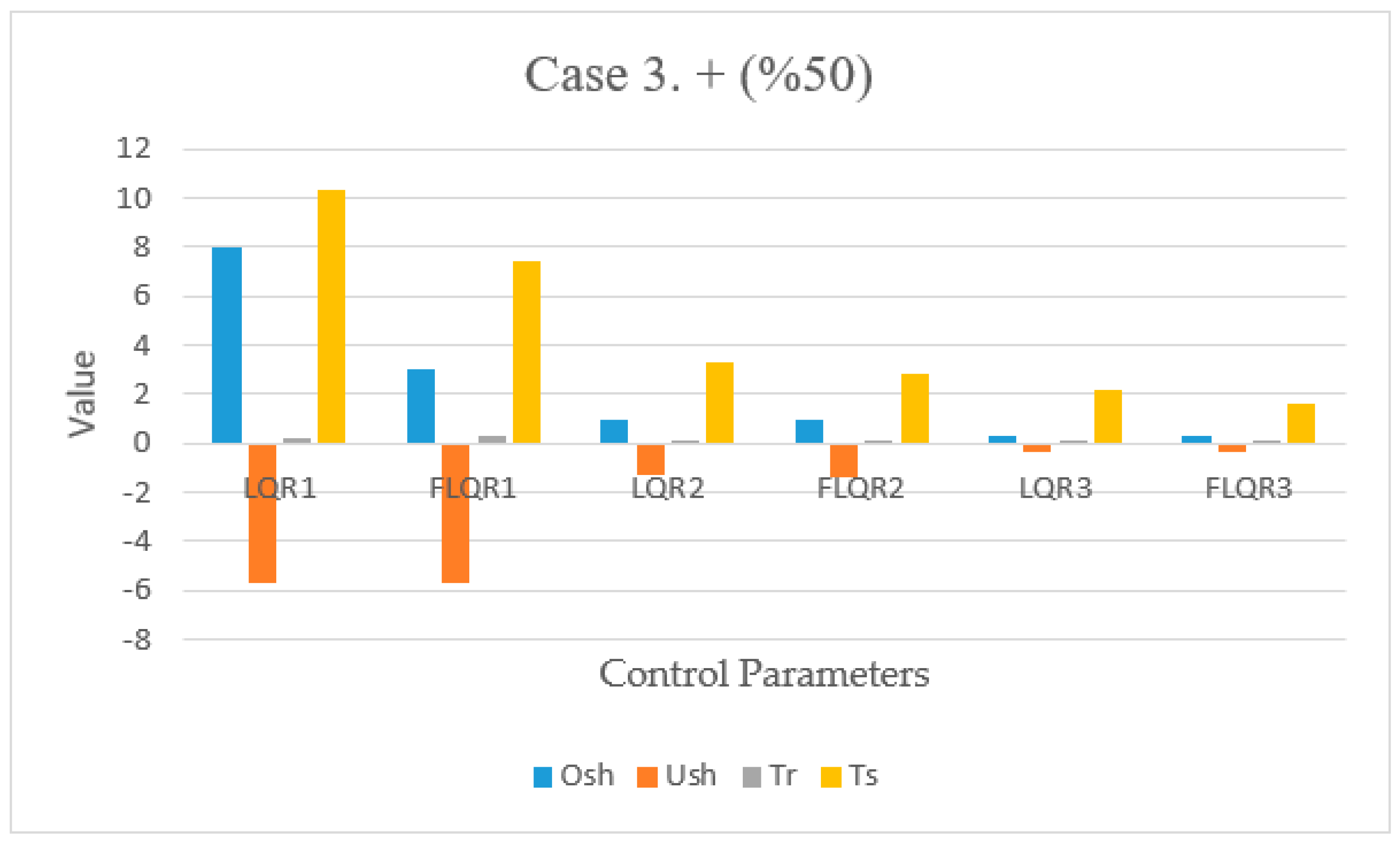
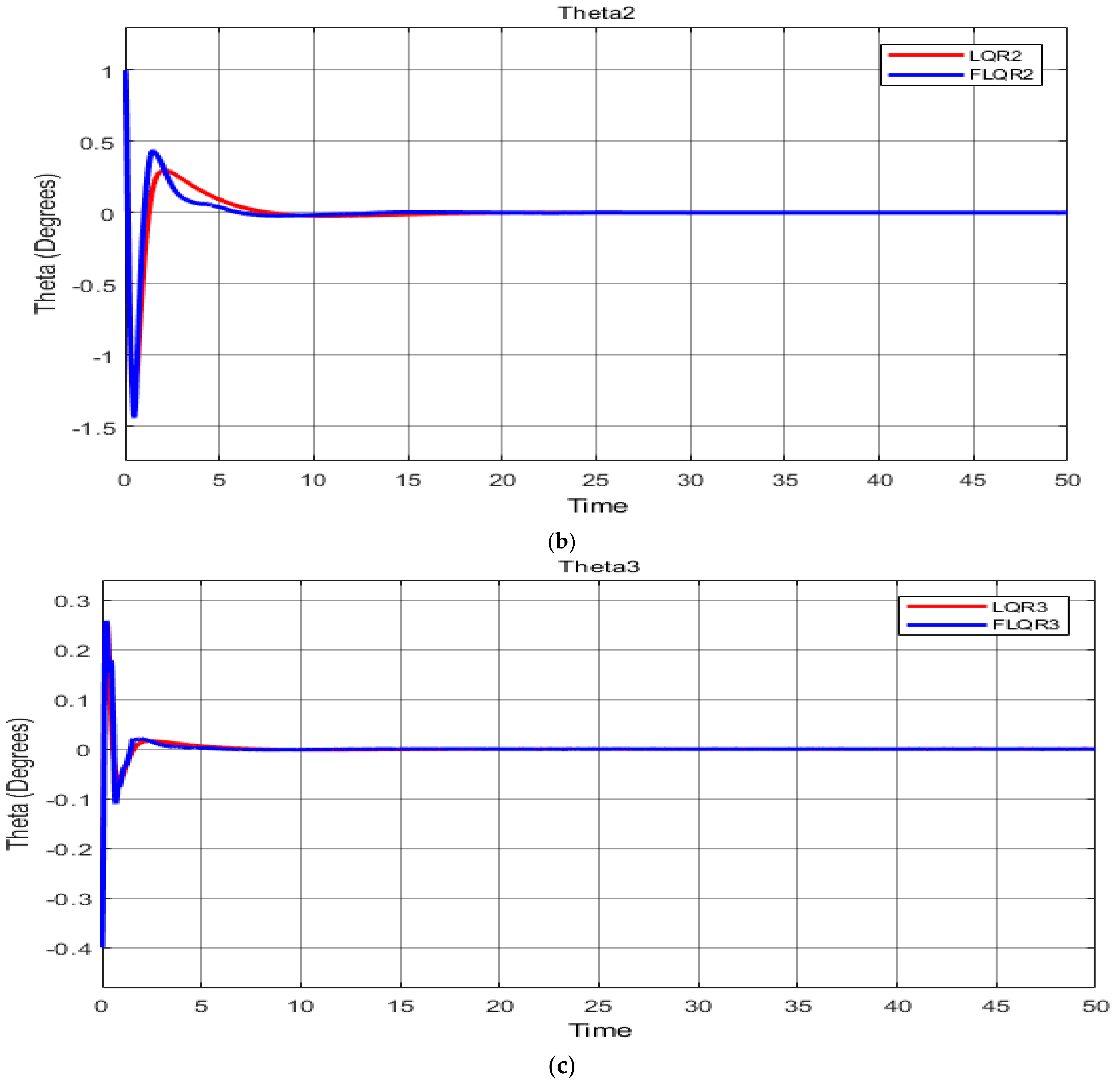
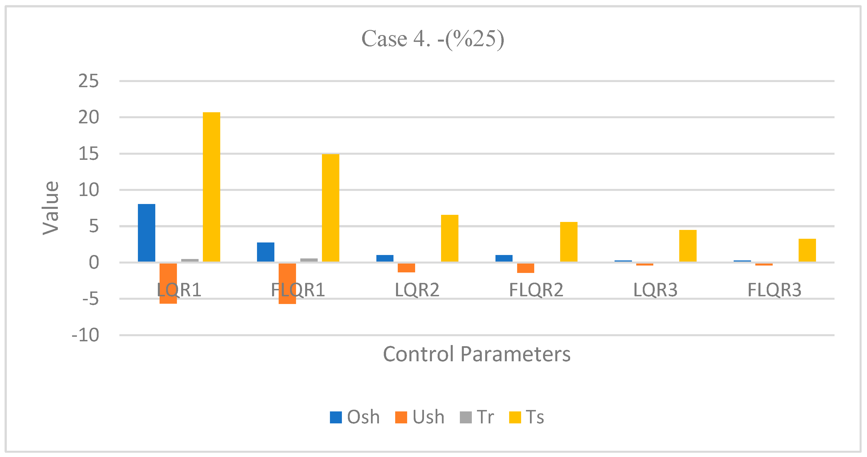
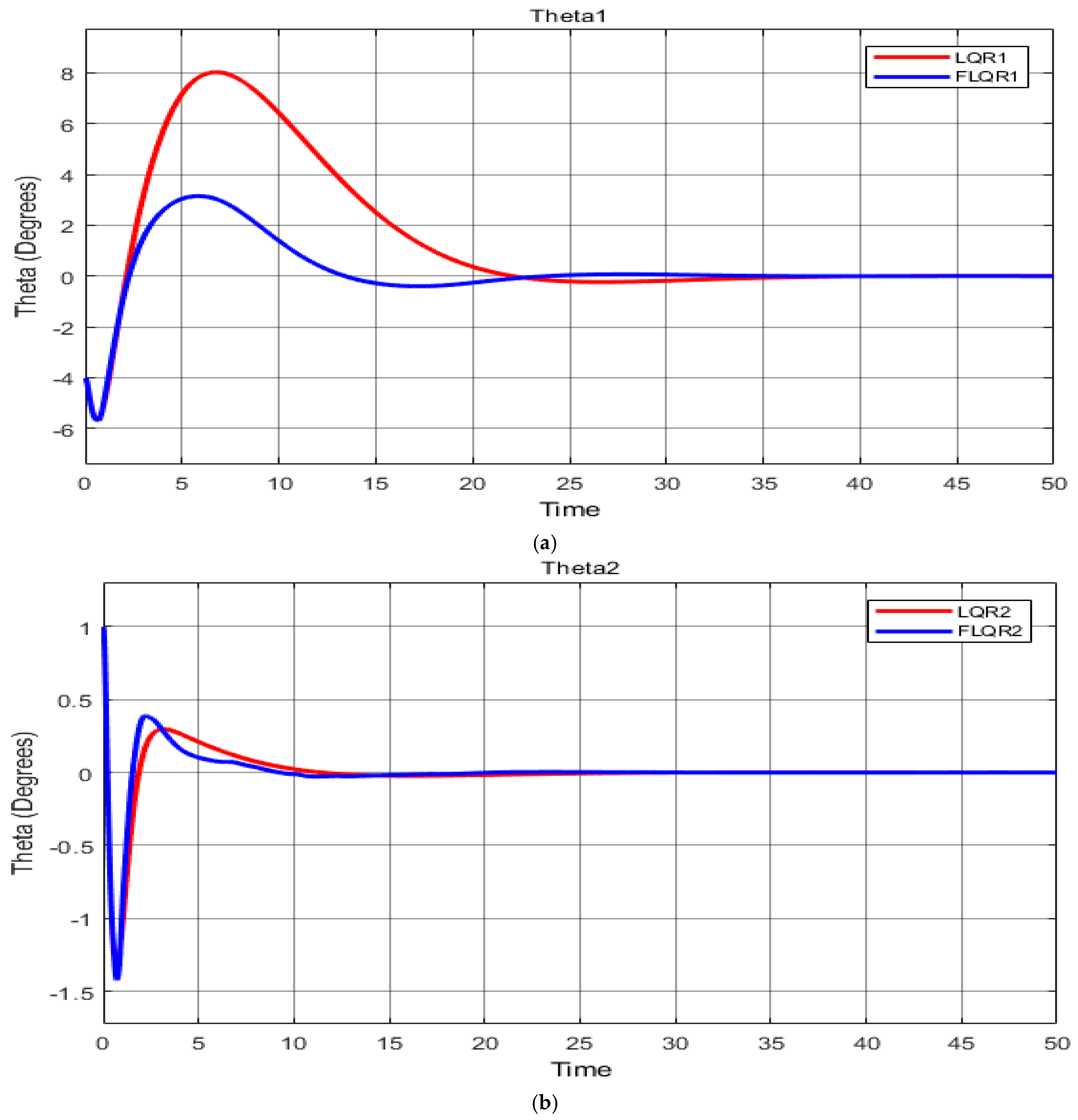
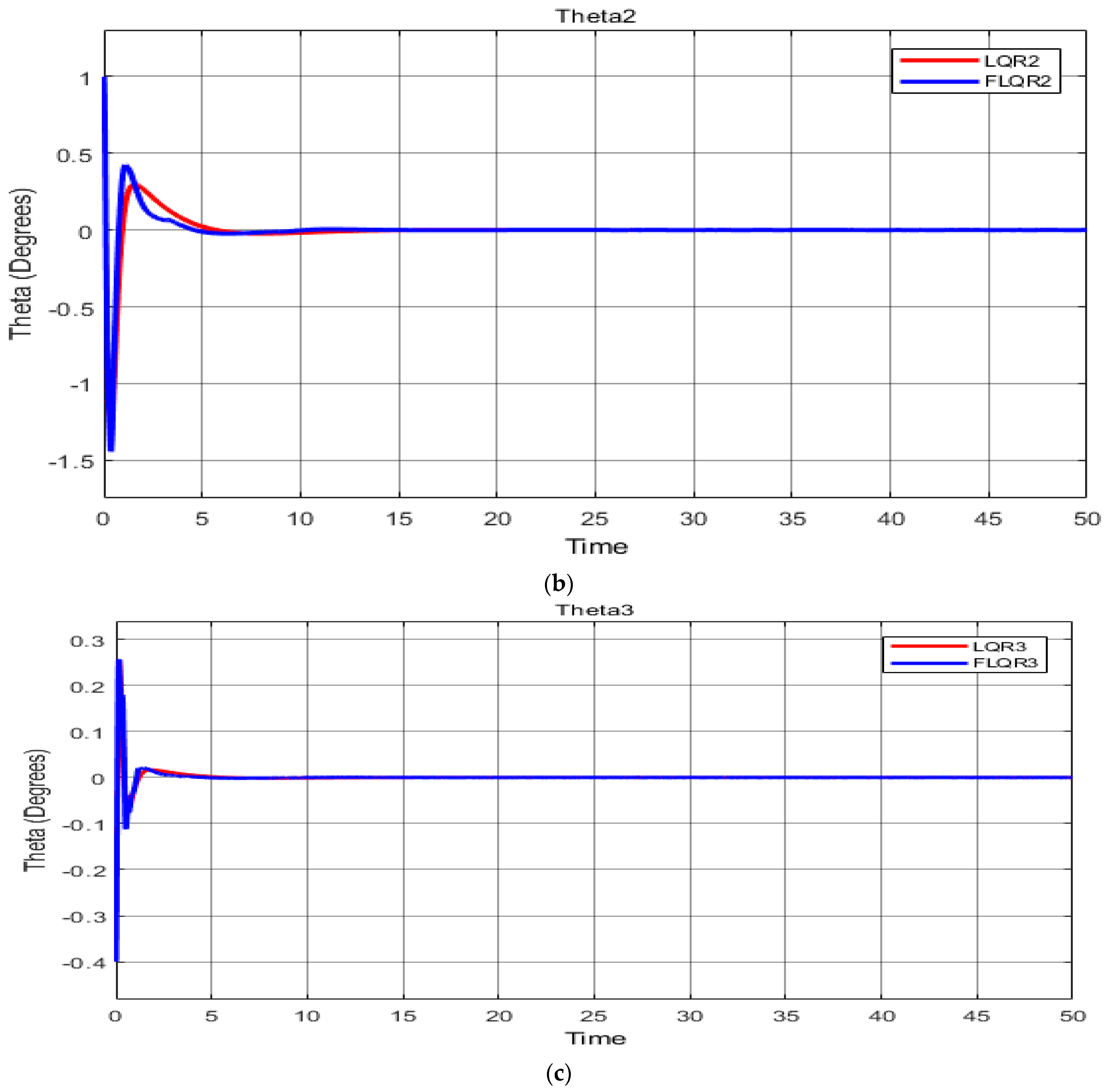
To evaluate both the LQR and the fuzzy LQR controller in terms of robust performance, variations were made to the testbed system as shown in Section 5, where the original values of both controllers were tested and compared as shown in Figure 7a–c, and Table 4. Figure 8 shows the controller in the original value where the Robogymnast parameters are constant. Then plus 25% of the original parameters were implemented in Section 5.2 for both LQR and FLQR which are signified in Figure 9a–c and the compared outcomes are displayed in Figure 10 and Table 5 to show the difference between cases 1 and 2. A third scenario is by adding 50% more of the original parameters to verify the stability as seen in Figure 11a–c and Figure 12 and Table 6. On the other hand, −25% and −50% were implemented respectfully to the robotic system to verify the response of the system as seen in Section 5.4 in which case 4 is compared in Table 7. Moreover, Figure 13a–c and Figure 14 insulate the outcomes of −25% of the system. In the last scenario, −50% less of the original value was applied to the initial values as it can be seen in Table 8, and the difference is presented in Figure 15a–c and Figure 16. Finally, Section 5.6 demonstrates the integral time of absolute error (ITAE) for each case 1−5, then Table 9. Figure 17 demonstrates the comparison between LQR and FLQR controllers in all scenarios respectively. As a result, parametric uncertainty conditions were formed that might frequently be encountered operationally within the testbed. Optimal gains were achieved in all cases; there are multiple variables within the testbed system that can change as operations are running and increases or decreases in any of this impact how stable the system is, where the parameters change mathematically.

5. Results

5.1. Case 1: Original Value [17]

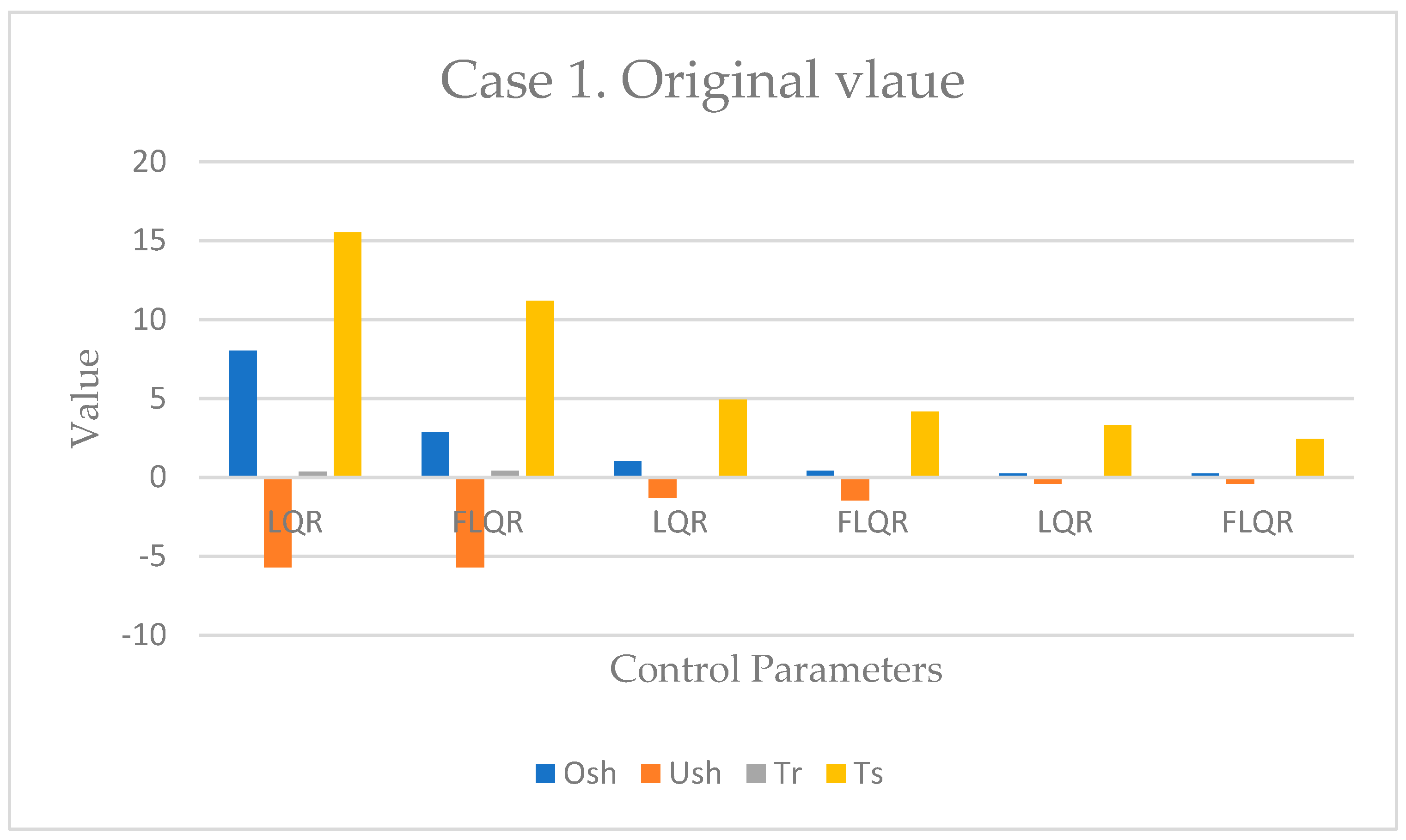
As shown, Figure 8 displayed the controller in the original value where the Robogymnast parameters are constant.
Figure 8. Case 1 comparison.
Knowledge 02 00028 g008

5.2. Case 2: +(%25)

In Table 5, a full outcome of case2 comparison between LQR and FLQR controllers is presented.
Figure 9. (a) The system response for link-1 of Robogymnast in Case 2 (T1); (b) The system response for each middle link of Robogymnast in Case 2 (T2); (c) The system response for link-3 of Robogymnast in Case 2 (T3).
Knowledge 02 00028 g009aKnowledge 02 00028 g009b
Table 5. Comparison performance of LQR and FLQR controllers in Case 2.
SymbolController O s h (pu) U s h (pu) T r (s) T s (s)
θ 1 LQR8.026−5.6210.284412.4151
Fuzzy LQR3.122−5.7160.32498.9536
θ 2 LQR1−1.3260.06053.9305
Fuzzy LQR1−1.4450.843.3397
θ 3 LQR0.2537−0.40.04062.6648
Fuzzy LQR0.2562−0.40.04181.9637
Figure 10. Case 2 comparison.
Knowledge 02 00028 g010

5.3. Case 3: +(%50)

As shown, Table 6 presents the controller in the case 3 value where the Robogymnast parameters are add +(50) to LQR and FLQR to investigate the difference.
Table 6. Comparison performance of LQR and FLQR controllers in Case 3.
SymbolController O s h (pu) U s h (pu) T r (s) T s (s)
θ 1 LQR8.025−5.6790.236910.3460
Fuzzy LQR3.013−5.7110.27097.4641
θ 2 LQR1−1.3260.05043.2747
Fuzzy LQR1−1.4330.04862.7863
θ 3 LQR0.2542−0.40.03372.2205
Fuzzy LQR0.2582−0.40.481.6402
Figure 11. (a) The system response for upper link of Robogymnast in Case 3 (T1); (b) The system response for second link of Robogymnast in Case 3 (T2); (c) The system response for 3rd link of Robogymnast in Case 3 (T3).
Knowledge 02 00028 g011
Figure 12. Case 3 comparison.
Knowledge 02 00028 g012

5.4. Case 4: −(%25)

In Table 7, a full outcome of case 5 comparison between LQR and FLQR controllers is described to verify the system stability.
Figure 13. (a) The system response for 1st link of Robogymnast in Case 4 (T1); (b) The system response for central link of Robogymnast in Case 4 (T2); (c) The system response for link-3 of Robogymnast in Case 4 (T3).
Knowledge 02 00028 g013aKnowledge 02 00028 g013b
Table 7. Comparison performance of LQR and FLQR controllers in Case 4.
SymbolController O s h   ( pu ) U s h   ( pu ) T r   ( s ) T s   ( s )
θ 1 LQR8.025−5.6790.474420.6922
Fuzzy LQR2.742−5.7120.544514.8923
θ 2 LQR1−1.3260.10126.5537
Fuzzy LQR1−1.4370.09755.5485
θ 3 LQR0.2546−0.40.06814.4410
Fuzzy LQR0.2584−0.40.06993.2399
Figure 14. Case 4 comparison.
Knowledge 02 00028 g014

5.5. Case 5: −(%50)

Finally, in Table 8 a full result of case5, the LQR and FLQR controllers’ comparison is illustrated to validate the system stability.
Figure 15. (a) The system response for the first link of Robogymnast in Case 5 (T1); (b) The system response for the 2nd link of Robogymnast in Case 5 (T2); (c) The system response for the lower link of Robogymnast in Case 5 (T3).
Knowledge 02 00028 g015aKnowledge 02 00028 g015b
Table 8. Comparison performance of LQR and FLQR controllers in Case 5.
SymbolController O s h   ( pu ) U s h   ( pu ) T r   ( s ) T s   ( s )
θ 1 LQR8.025−5.6790.71131.0403
Fuzzy LQR3.146−5.7060.795221.3793
θ 2 LQR1−1.36260.15209.8323
Fuzzy LQR1−1.4210.14837.8387
θ 3 LQR0.2548−0.40.10246.6633
Fuzzy LQR0.2604−0.40.10604.8405
Figure 16. Case 5 comparison.
Knowledge 02 00028 g016

5.6. Compression of ITAE

This section shows the integral time of absolute error for every case investigated, which are original, (±25%), and (±50) values, respectively, in both the LQR and FLQR controllers in all cases examined as mentioned above (Table 9).
Figure 17. ITAE comparison.
Knowledge 02 00028 g017
Table 9. ITAE values.
Case 1Case 2Case 3Case 4 Case 5
LQR1159.7283.9102.2031.040370.98
FLQR121.2938.1626.7287.198.971
LQR20.3220.57410.21361.290.148
FLQR20.3130.53090.20661.2570.143
LQR30.0220.03950.01380.0880.009
FLQR30.0210.03850.01420.0860.009

5.7. Comparison of LQR and FLQR in All Cases

Table 10 shows a full comparision between LQR and FLQR in all cases implemented where (±25%) and (±50%) added to the system to test their stabilty and robostance. As well as Figure 18 illustrates the comparions between the system outcomes for 5 different cases in terms of Over and undershoot, rising and settling time in both controllers examined.
Table 10. Comparison of LQR and FLQR in all cases.
CaseSymbolController O s h   ( pu ) U s h   ( pu ) T r   ( s ) T s   ( s )
Original value θ 1 LQR8.02−5.690.355715.5196
Fuzzy LQR2.88−5.710.407411.1823
θ 2 LQR1.03−1.320.07584.9142
Fuzzy LQR0.42−1.440.07304.1694
θ 3 LQR0.25−0.410.05093.3310
Fuzzy LQR0.25−0.400.05232.4428
Case 2 θ 1 LQR8.026−5.6770.284412.4151
Fuzzy LQR3.122−5.7160.32498.9536
θ 2 LQR1−1.3260.06053.9305
Fuzzy LQR1−1.4450.05843.3397
θ 3 LQR0.2537−0.40.04062.6648
Fuzzy-LQR0.2562−0.40.04181.9637
Case 3 θ 1 LQR8.025−5.6790.236910.3460
Fuzzy LQR3.013−5.7110.27097.4641
θ 2 LQR1−1.3260.05043.2747
Fuzzy LQR1−1.4330.04862.7863
θ 3 LQR0.2542−0.40.03372.2205
Fuzzy LQR0.2582−0.40.03481.6402
Case 4 θ 1 LQR8.025−5.6790.474420.6922
Fuzzy LQR2.742−5.7120.544514.8923
θ 2 LQR1−1.3260.10126.5537
Fuzzy LQR1−1.4370.09755.5485
θ 3 LQR0.2546−0.40.06814.4410
Fuzzy LQR0.2584−0.40.06993.2399
Case 5 θ 1 LQR8.025−5.6790.71131.0403
Fuzzy LQR3.146−5.7060.795221.3793
θ 2 LQR1−1.36260.15209.8323
Fuzzy LQR1−1.4210.14837.8387
θ 3 LQR0.2548−0.40.10246.6633
Fuzzy LQR0.2604−0.40.10604.8405
Figure 18. LQR and FLQR comparison.
Knowledge 02 00028 g018

6. Discussion

The proposed FLQR controller, as a combined LQR and fuzzy logic control method, performed well for the three-link Robogymnast robotics system, with the examination of the system’s robustness showing that it outperformed the conventional controller across all variables, including time to settle and under- and over-shoot. A more detailed summary of the findings for robustness is provided here.
For the first scenario, the measured system response is shown in Figure 7a–c and Table 8, giving baseline systems values with no alterations. Comparing the LQR with the FLQR controller, the latter shows decreased overshoot (Osh) and undershoot (Ush), with respective overshoot values of 8.02 and 2.88. In addition, while the LQR controller’s rise time was faster (c. 0.35 s), the FLQR showed a faster settling time (11.18 s).
For the second case, in which the mathematical model values are increased by 25%, Table 5 shows the performance comparison between the two controllers examined for robustness. For the LQR controller, undershoot and overshoot did not differ significantly, but there was a difference of 0.07 s in rise time, and the settling time dropped to 12.41 s from 15.51 s. In contrast, the findings for FLQR demonstrate an increase in overshoot of approximately 0.242 pu, with no alteration in undershoot, and reductions in settling and rising times for the controllers. In addition, for LQR, there was a slight decrease in second angle θ 2 overshoot, while undershoot did not change significantly and the times were reduced for each parameter. For FLQR, decreases were found across each parameter. Finally, for θ 3 , no change was seen in under- or overshoot for the LQR controller, although reductions occurred in the rising and settling times. For FLQR, time decreases were also found, while the values of the remaining parameters were unchanged from the initial scenario.
In the third scenario, values were increased by 50% over the system’s baseline. While overshoot remained unchanged for the LQR, undershoot altered only slightly, from −5.69 at baseline to −5.67, but both the rising and settling times were quicker, altering from 0.35 to 0.24 s for rising and a slightly change of 5 s for the settling time. For link θ 2 with the LQR controller, there was no change in under- or overshoot, but a reduction in the two time variables. Meanwhile, for the FLQR controller, times were also reduced, while no change was seen for under- and overshoot. For the third link θ 3 , again, under- and overshoot remained the same, while smaller values were found for the time variables.
For the fourth scenario, system variables were reduced by 25%, as shown in Table 7. In the first link, for the LQR, a one-second increase in rising time was recorded for the LQR, and settling time was observed to change by roughly 5 s against the original case, from 15.51 to 20.69 s. By contrast, the FLQR controller produced lower values for each time parameter, and only very small differences for the remaining variables. Moreover, for θ 2 , there was little change in under- or overshoot, with reductions in rising and settling times. Finally, for θ 3 , a small increase in rising time was seen compared with the original scenario, from 0.052 to 0.0699 s. Settling time was altered by approximately 1 s, with no changes in under- or overshoot.
The final scenario reduced the system parameters by 50% and, again, stability and response were tested to indicate robustness. It is notable here that for the LQR controller, each of the links displayed small increases in rising and settling time differences, with major alterations in overshoot and undershoot. In contrast, FLQR performed markedly better here than the conventional controller. Settling times across each link were 21.37 s, 7.83 s and 4.83 s, with higher rising times for each of the links. Under- and overshoot were also greater across each link. Table 10 offers a comparison of all the findings in all cases and scenarios between each link.

7. Conclusions and Future Work

This paper has presented modelling and simulation for the application of an LQR/fuzzy logic controller to stabilise a robotic gymnast system in MATLAB/Simulink. In this study, an FLQR was developed and then compared against an established LQR control approach for the Robogymnast. Mathematical modelling was performed for the starting values of variables within the pendulum-based system, and then a comprehensive model for the simulation of a robotic manipulation drive with the FLQR controller was developed. The primary variables were established, with calculations for overshoot as well as settle and rise times. An assessment was performed for the dynamic performance of the system. Calculations for stability and robustness were performed for each of the FLQR and LQR controllers, with comparisons across each scenario, in which variables were increased or decreased by several values. The results of the comparison show that the proposed FLQR controller performs better with the Robogymnast than does the established LQR controller.
To conclude, it is possible to declare that this work involved the investigation of the modulation of a triple-link robotics mechanism for the swing-up position, and the selected controller can be further extended to implement optimized algorithms for additional studies. In conclusion, this study examining the control of swing-up in three-link robotic systems suggests that the controller proposed here could be studied further and implemented in different optimised algorithms.
Author Contributions

Conceptualization, B.A.s. and M.M.; methodology, B.A.s. and F.A.; software, B.A.s. and M.M.; validation, B.A.s. and Y.M.; formal analysis, B.A.s. and F.A.; investigation, B.A.s. and M.M.; resources, B.A.s. and Y.M.; data curation, B.A.s. and M.M.; writing—original draft preparation, B.A.s. and F.A.; writing—review and editing, B.A.s. and Y.M.; visualization, B.A.s. and M.M.; supervision, B.A.s., F.A., and Y.M.; project administration, F.A.; funding acquisition, B.A.s. All authors have read and agreed to the published version of the manuscript.

Funding

This paper is part of the research of the corresponding author, B.A.s., who is sponsored by the Ministry of Higher Education and Scientific Research in Libya.

Institutional Review Board Statement

Not applicable.

Informed Consent Statement

Not applicable.

Data Availability Statement

Not applicable.

Acknowledgments

The authors would like to thank Cardiff University/School of Engineering for accepting to pay the APC towards publishing this paper.

Conflicts of Interest

The authors declare no conflict of interest.

Abbreviations

RobogymnastRobot Gymnast
FLQR Fuzzy logic quadrate rectangular
LQR Linear quadrate rectangular
PIDProportional integral derivative
ITAEIntegral time of absolute error
OshOvershoot
UshUndershoot
T r Rising time
T s Settling time

References

  1. Rahmani, R.; Mobayen, S.; Fekih, A.; Ro, J.-S. Robust Passivity Cascade Technique-Based Control Using RBFN Approximators for the Stabilization of a Cart Inverted Pendulum. Mathematics 2021, 9, 1229. [Google Scholar] [CrossRef]
  2. Hazem, Z.B.; Fotuhi, M.J.; Bingül, Z. Development of a Fuzzy-LQR and Fuzzy-LQG stability control for a double link rotary inverted pendulum. J. Frankl. Inst. 2020, 357, 10529–10556. [Google Scholar] [CrossRef]
  3. Eldukhri, E.; Pham, D.T. Autonomous Swing-Up Control of a Three-Link Robot Gymnast. Proc. Inst. Mech. Eng. Part I J. Syst. Control. Eng. 2010, 224, 825–832. [Google Scholar] [CrossRef]
  4. Ismail, H.; Eldhukhri, E.; Packianather, M.S. Invasive weed optimization of swing-up control parameters for robot gymnast. In Proceedings of the 2014 IEEE/ASME International Conference on Advanced Intelligent Mechatronics, Besacon, France, 8–11 July 2014. [Google Scholar]
  5. Lai, X.; Wu, M.; She, J.; Zhang, A. Motion control of underactuated three-link gymnast robot based on combination of energy and posture. IET Control Theory Appl. 2011, 5, 1484–1493. [Google Scholar] [CrossRef]
  6. Muskinja, N.; Tovornik, B. Swinging up and stabilization of a real inverted pendulum. IEEE Trans. Ind. Electron. 2006, 53, 631–639. [Google Scholar] [CrossRef]
  7. Spong, M. The swing up control problem for the Acrobot. IEEE Control Syst. 1995, 15, 49–55. [Google Scholar] [CrossRef]
  8. Medrano-Cerda, G.A.; Eldukhri, E.E.; Cetin, M. Balancing and Attitude Control of Double and Triple Inverted Pendulums. Trans. Inst. Meas. Control 1995, 17, 143–154. [Google Scholar] [CrossRef]
  9. Lopez de Lacalle, L.; Lamikiz, A.; Sanchez, J.; Fernandez de Bustos, I. Simultaneous Measurement of Forces and Machine Tool Position for Diagnostic of Machining Tests. IEEE Trans. Instrum. Meas. 2005, 54, 2329–2335. [Google Scholar] [CrossRef]
  10. Lakshmi, K. Design of Robust Energy Control for Cart-Inverted Pendulum. Int. J. Eng. Technol. 2007, 4, 66–76. [Google Scholar]
  11. Pham, D.; Darwish, A.H.; Eldukhri, E. Optimisation of a fuzzy logic controller using the Bees Algorithm. Int. J. Comput. Aided Eng. Technol. 2009, 1, 250. [Google Scholar] [CrossRef]
  12. Kamil, H.; Eldukhri, E.; Packianather, M. Balancing Control of Robot Gymnast Based on Discrete-Time Linear Quadratic Regulator Technique. In Proceedings of the 2014 2nd International Conference on Artificial Intelligence, Modelling and Simulation, Madrid, Spain, 18–20 November 2014. [Google Scholar]
  13. Ismail, H.A.; Packianather, M.S.; Grosvenor, R.I. Multi-objective invasive weed optimization of the LQR controller. Int. J. Autom. Comput. 2017, 14, 321–339. [Google Scholar] [CrossRef]
  14. Eldukhri, E.E.; Kamil, H.G. Optimisation of swing-up control parameters for a robot gymnast using the Bees Algorithm. J. Intell. Manuf. 2013, 26, 1039–1047. [Google Scholar] [CrossRef]
  15. Featherstone, R. A simple model of balancing in the plane and a simple preview balance controller. Int. J. Robot. Res. 2017, 36, 1489–1507. [Google Scholar] [CrossRef]
  16. Ismail, H.A.; Packianather, M.S.; Grosvenor, R.I.; Eldhukri, E.E. The application of IWO in LQR controller design for the Robogymnast. In Proceedings of the 2015 SAI Intelligent Systems Conference (IntelliSys), London, UK, 10–11 November 2015. [Google Scholar]
  17. Samad, B.A.; Anayi, F.; Melikhov, Y.; Mohamed, M.; Altayef, E. Modelling of LQR and Fuzzy-LQR Controllers for Stabilisation of Multi-link Robotic System (Robogymnast). In Proceedings of the 2022 8th International Conference on Automation, Robotics and Applications (ICARA), Prague, Czech Republic, 18–20 February 2022. [Google Scholar]
  18. Samad, B.A.; Mohamed, M.; Anavi, F.; Melikhov, Y. A hybrid Fuzzy approach of different controllers to stabilize a 3-link swinging robotic (Robogymnast). In Proceedings of the 2022 2nd International Conference on Advance Computing and Innovative Technologies in Engineering (ICACITE), Greater Noida, India, 28–29 April 2022. [Google Scholar]
  19. Mohamed, M.; Anayi, F.; Packianather, M.; Samad, B.A.; Yahya, K. Simulating LQR and PID controllers to stabilise a three-link robotic system. In Proceedings of the 2022 2nd International Conference on Advance Computing and Innovative Technologies in Engineering (ICACITE), Greater Noida, India, 28–29 April 2022. [Google Scholar]
  20. Luhao, W.; Zhanshi, S. LQR-Fuzzy Control for Double Inverted Pendulum. In Proceedings of the 2010 International Conference on Digital Manufacturing & Automation, Changcha, China, 18–20 December 2010. [Google Scholar]
  21. Yaren, T.; Kizir, S. Stabilization Control of Triple Pendulum on a Cart. In Proceedings of the 2018 6th International Conference on Control Engineering & Information Technology (CEIT), Istanbul, Turkey, 25–27 October 2018. [Google Scholar]
  22. Heidar, M.; Fadaei, K.; Ali, S.; Pahnehkolaei, H.; Jafari, M. Design of Hybrid Fuzzy-PD Controller for an Inverted Pendulum. Majlesi J. Mechatron. Syst. 2021, 10, 21–27. [Google Scholar]
  23. Ben-Mubarak, M.A.; Ali, B.M.; Noordin, N.K.; Ismail, A.; Ng, C.K. Fuzzy Logic Based Self-Adaptive Handover Algorithm for Mobile WiMAX. Wirel. Pers. Commun. 2012, 71, 1421–1442. [Google Scholar] [CrossRef]
  24. Adamu, J.K.; Hamza, M.F.; Isa, A.I. Performance Comparisons Of Hybrid Fuzzy-LQR And Hybrid PID-LQR Controllers On Stabilizing Double Rotary Inverted Pendulum. J. Appl. Mater. Technol. 2020, 1, 71–80. [Google Scholar] [CrossRef]
  25. Isa, A.I.; Hamza, M.F.; Muhammad, M. Hybrid fuzzy control of nonlinear inverted pendulum system. arXiv 2019, arXiv:1910.07995. [Google Scholar]
  26. Ismail, H.A. Intelligent Model-Based Control of Complex Multi-Link Mechanisms. Ph.D. Thesis, Cardiff University, Cardiff, UK, December 2016. [Google Scholar]
  27. Kamil, H.G. Intelligent Model-Based Control of Complex Three-Link Mechanisms. Ph.D. Thesis, Cardiff University, Cardiff, UK, April 2015. [Google Scholar]
  28. Kumar, E.V.; Jerome, J. Robust LQR Controller Design for Stabilizing and Trajectory Tracking of Inverted Pendulum. Procedia Eng. 2013, 64, 169–178. [Google Scholar] [CrossRef]
  29. Hazem, Z.B.; Fotuhi, M.J.; Bingül, Z. A Study of Anti-Swing Fuzzy LQR Control of a Double Serial Link Rotary Pendulum. IETE J. Res. 2021. [Google Scholar] [CrossRef]
  30. Bekkar, B.; Ferkous, K. Design of Online Fuzzy Tuning LQR Controller Applied to Rotary Single Inverted Pendulum: Experimental Validation. Arab. J. Sci. Eng. 2022, 1–16. [Google Scholar] [CrossRef]
  31. Habib, M.K.; Ayankoso, S.A. Modeling and Control of a Double Inverted Pendulum Using LQR with Parameter Optimization through GA and PSO. In Proceedings of the 2020 21st International Conference on Research and Education in Mechatronics (REM), Cracow, Poland, 9–11 December 2020. [Google Scholar] [CrossRef]
  32. Yong, Q.; Yanlong, L.; Xizhe, Z.; Ji, L. Balance control of two-wheeled self-balancing mobile robot based on TS fuzzy model. In Proceedings of the Proceedings of 2011 6th International Forum on Strategic Technology, Harbin, China, 22–24 August 2011. [Google Scholar]
  33. Maraslidis, G.S.; Kottas, T.L.; Tsipouras, M.G.; Fragulis, G.F. A Fuzzy Logic Controller for Double Inverted Pendulum on a Cart. In Proceedings of the 2021 6th South-East Europe Design Automation, Computer Engineering, Computer Networks and Social Media Conference (SEEDA-CECNSM), Preveza, Greece, 24–26 September 2021. [Google Scholar]
  34. El-Hawwary, M.; Elshafei, A.; Emara, H.; Fattah, H. Adaptive Fuzzy Control of the Inverted Pendulum Problem. IEEE Trans. Control Syst. Technol. 2006, 14, 1135–1144. [Google Scholar] [CrossRef]
Figure 1. Robogymnast.
Knowledge 02 00028 g001
Figure 2. LQR simulation.
Knowledge 02 00028 g002
Figure 7. (a) The system response for the upper link of Robogymnast in Case 1 (T1); (b) The system response for the middle link of Robogymnast in Case 1 (T2); (c) The system response for lower link of Robogymnast in Case 1 (T3).
Knowledge 02 00028 g007aKnowledge 02 00028 g007b
Table 4. LQR vs. FLQR performance [13].
SymbolController O s h   ( pu ) U s h   ( pu ) T r   ( s ) T s   ( s )
θ 1 LQR8.02−5.690.355715.5196
Fuzzy LQR2.88−5.710.407411.1823
θ 2 LQR1.03−1.320.07584.9142
Fuzzy LQR0.42−1.440.304.1694
θ 3 LQR0.25−0.410.05093.3310
Fuzzy LQR0.25−0.400.05232.4428
Publisher’s Note: MDPI stays neutral with regard to jurisdictional claims in published maps and institutional affiliations.