Abstract
Construction is considered an ecosystem that incorporates many technical, legal, and practical aspects. This article focuses on the practical side of construction, specifically on the use of BIM (building information modeling) during the design phase. In the construction industry, BIM ensures better collaboration and project management by centralizing all information on the same platform. It allows each project stakeholder to exchange documents in real time and contribute to resolving any unforeseen issues or constraints that are encountered. Following an extensive literature review, it has been demonstrated that a lack of communication and collaboration among stakeholders is considered one of the major obstacles to the widespread use of BIM in architectural offices and agencies. The main contribution of this work is to clarify the roles of stakeholders and the rights and temporalities of access, consultation, and modification of the digital BIM model. To achieve this, a collaborative engineering method was applied to propose organizational models for the work of construction stakeholders who are using a collaborative engineering approach during the initial stage of a project (design phase), in order to define the roles of stakeholders and their access to the BIM model.
1. Introduction
An architectural project, as a process, extends over several phases, from programming to delivery, and requires the involvement of a large number of participants from several fields. These participants are obliged to work collectively to accomplish the various tasks involved in the project. Drawings and 2D plans are used for the design of the project, and the drawings of the plans are made by hand or with the help of CAD software (computer aided design). Files are exchanged between the various players on the basis of different views of the building (elevations, floor plans, cross-sections, etc.), as each body works in an individual way and then sends their drawings to the project management team. This meant that not all the details and interactions between the different elements of the building were communicated. This made it difficult to manage changes, co-ordinate, and resolve problems, which in turn led to more and more errors and delays, and the loss of productivity. With the advent of digital technology, a new concept was created—BIM (Building Information Modeling)—to improve efficiency and quality in the design, construction, and management of buildings.
There is an abundance of definitions related to BIM and a variety of terminologies are used to describe it. The NF standard ISO 19650 on information management defines BIM as construction information modelling “the use of a shared digital representation of a built asset to facilitate the design, construction and operation processes so as to provide a reliable basis for decision making” [1]. Built assets include, but are not limited to, buildings, bridges, roads, and factories, according to the BIM Glossary from “buildingSMART France”1, the association of BIM players in France [2]. BIM is a method of working together around a digital model. All the participants in the construction process create, publish, and use the model, extracting the information they need for their own part of the project. In turn, they provide the model with new information to produce informed virtual objects. According to the National Building Information Modeling Standard [3], “the Building Information Model (BIM) is a digital representation of the physical and functional characteristics of an installation. As such, it serves as a shared knowledge resource for information about an installation forming a reliable basis for decisions throughout its lifecycle from the outset”.
The aim of the BIM process is to ensure better coordination and closer collaboration between the parties involved in a project by centralizing data in a shared digital model. The use of BIM digital models provides a detailed and realistic model of the building, making it easier for all stakeholders to visualise and understand the project, helping to detect potential conflicts between the different elements of a project from the outset, and to reduce and identify errors, delays, and additional costs that may arise during the construction and management phases. Centralizing building information, such as costs and materials, in a single digital 3D model enables data, schedules, and budgets to be managed for each project task, and assists in the long-term management, operation, and maintenance of the building [4,5].
2. Literature Review
BIM is being adopted more and more in the construction industry, and many researchers around the world have taken an interest in it. A number of studies and surveys have been carried out on the adoption of BIM, including the case of smartMarket [6], the assessment of the Digital Transition Plan for the Building Industry [7], and a survey of the use of BIM by design offices [8]. Hochscheid and Halin [9], in their article on the BIM barometer, carried out a survey on the adoption of BIM in architectural practices in France based on numerous national and international studies and summarized the major difficulties in the adoption of BIM in France through surveys of architectural practices.
In their paper on barriers to BIM implementation in construction, Bayat et al. [10] classified the failure factors of its application using the network analysis process (NAP) model. The study selected and evaluated barriers such as financial barriers, human resources, time, and technical issues. An extensive literature review revealed that one of the biggest barriers to the implementation of BIM is a lack of collaboration and communication and the high cost of designing with BIM. The dispersion of information and the lack of an integrated system [2] are also factors that significantly impact the failure of BIM implementation.
The process of constructing a BIM architectural project comprises three parts: the legal part, which varies from one country to another depending on the regulations in force and the absence of BIM standards in some countries; the technical part, which depends on the components and nature of the project, as well as the digital tools chosen by the stakeholders; and the practical part, which is influenced by the size and nature of the project. This study focuses on the practical aspect of the process. The construction phases of an architectural project are generally the same throughout the world, which enables the development of a universally applicable solution that can be adapted according to the nature and size of the project.
The issue addressed in this research is the lack of collaboration and communication between the players involved in BIM construction. The construction process of a BIM architectural project in France will be used as a case study because, according to Hochscheid [11], in his article on “The adoption of BIM in architectural agencies in France”, France is not very represented in the literature as it is not one of the leaders in this field.
Several solutions have been proposed in response to this problem. Notably, Boton [12], in his thesis, proposed a multiple-view design method that meets the professional needs of participants in a collaborative 4D simulation. The research examines planning practices in the construction sector, theories of information visualization and view design, and computer-supported collaborative work. In his thesis, Zignale [12] proposes the PUSH (practices and usages-based services enhancement) method, aiming to ensure a holistic and multidisciplinary approach to the design of adapted services, emphasizing communication between stakeholders and the traceability of decisions throughout the development process. Various research fields are incorporated, including software engineering, the design of human–machine interfaces, service-oriented enterprises, the design of information systems, and computer-supported collaborative work.
3. Materials and Methods
Based on research into the challenges of BIM in various construction phases and previous work, this article aims to solve the problem of collaboration between construction stakeholders from a practical perspective. Through collaborative engineering CE, this article attempts to answer the question: how can we define the roles of the participants and their access to the model, their temporality, and their modality (consultation, addition, modification).
The aim of this research is to define the points of collaboration and communication between the players and to facilitate the work of agencies by producing organizational models that will serve as manuals for the implementation of BIM in agencies. These models will model the interactions and roles of each player in the different phases of the design stage.
The method proposed for application in this study is collaborative engineering in the field of construction. Collaborative engineering [13] is an approach to developing collaborative working methods for regular, high-value tasks, and implementing them in such a way that professionals can autonomously put them into practice, without constantly relying on the support of professional facilitators.
According to De Vreede and Briggs [14], the origins of collaborative engineering CE as a distinct area of scientific research can be traced back to a 2001 publication, which outlines a collaboration model language called “thinkLets” to teach novice team leaders repeatable and effective collaboration techniques [15]. The main objectives of collaborative engineering CE, according to De Vreede and Briggs [16,17], are, firstly, the design of effective and repeatable collaborative working processes, supported by technology, for high-value tasks. Secondly, the focus is on how to transfer the designs to practitioners (task domain experts who have no expertise in collaboration) with little or no training in tools or techniques. According to Kamal et al. [18], collaborative engineering enables practitioners (professionals, experts, etc.) to work with minimal cognitive load, aiming to make the collaborative process as easy and efficient as possible for practitioners by reducing the amount of mental effort required. At the same time, collaborative engineering seeks to equip these practitioners with facilitation skills (facilitating interactions between group members) and the necessary knowledge about other groups. However, Winkler et al. [19] add that the aim is also to transfer facilitation skills (the ability to lead and direct group interactions) and relevant knowledge about group dynamics and collaborative technology to practitioners [16].
Collaborative engineering was chosen because it is a method that shares objectives that are common with BIM. Collaborative engineering is to be implemented among a group of players—in this case, it will be applied among construction players, starting with two people, with or without a moderator. In the case of BIM, the number of participants varies according to the nature and phases of the project, and one of the major challenges encountered in implementing BIM is staff training. With the use of collaborative engineering, participants can work together with little or no training in tools or techniques.
Boton [20] confirms in his research that each construction project has its own constraints, objectives, and circumstances. Factors such as the geographical location, local regulations, weather conditions, client needs, and available resources all contribute to creating a distinct context for each project. In regards to these factors, collaborative engineering will assist in collaborating on all phases of the project with its efficient and repeatable collaborative work processes that are already designed and ready to be applied.
A construction project, whether public or private, involves a large number of participants [12] who are contractually bound during the various phases of the project according to construction law (public and private law), which varies from one country to another. In the context of this study, the legal side and the types of contracts between stakeholders have been intentionally omitted. Instead, the focus has been on examining their relationships during architectural practice in the first stage of the project, the design stage.
The method chosen in this work aims to address the problem of collaboration between stakeholders by proposing a model that is adapted to the architectural practice of BIM projects in France and around the world. This is based on the research work mentioned above, as well as feedback from two agencies in France, a technical engineering design office (Excity), a project management office, and a general construction contractor (Aquilis).
According to Joss et al. in their book “Construction Project Management” [12], construction law and the legal relationships between individuals (contract of enterprise, employment contract, mandate) vary from one country to another. Even if the construction stakeholders are the same and the tasks are the same, the contracts between them differ. The start date of the intervention can be modified according to the contract, which makes construction practices differ from one country to another and from one project to another.
In this research, a collaborative engineering method has been proposed to address this issue. The aim of collaborative engineering, as previously defined [15], is to design and deploy reproducible practices that can be carried out by practitioners without the ongoing support of external collaboration professionals (the facilitator). The method chosen in this research is the application of the 7-level collaboration model presented by Briggs et al. in [14]. This collaborative engineering model provides a guide for modeling collaborative activities and is applicable to construction projects; it simplifies modeling by allowing detailing of the phases of construction projects, the objective of each phase, and the relationships between stakeholders. In this work, the first three levels are sufficient for the organizational model of the architectural design process.
Table 1 presents the levels of collaboration that will be applied to the architectural project phases carried out in this research, along with their descriptions. As an example, the first level is “objective”, defined as the result or purpose of the work, which can be a group or individual objective. The lower level considers the product, describing the tangible or intangible result produced by the group work. The rest of the levels are described in order: activities, collaboration models, techniques, tools up to scripts/scenarios.

Table 1.
The 7-Level Collaboration Method by Briggs [14].
Based on the above model, our working method is organized into 4 main stages:
Stage 1: Proposal of new boundaries for the phases of the architectural project on which work will be carried out. Through a literature review, it was found that the boundaries of architectural project phases differ from one author to another, so we proposed new boundaries for the purposes of this research;
Step 2: Definition of objectives and tasks to be carried out in each stage and phase of the project with and without BIM;
Step 3: Definition of the stakeholders in each phase and their roles without and with BIM. By defining objectives, we will be able to understand and list the stakeholders who will be involved in each phase of the project. In fact, several stakeholders may participate in the phases of a project without producing any significant results (documents, plans); they may or may not give their agreement on the feasibility of the project, in order to anticipate changes. To do this, we need to specify all the people involved and their roles in each project phase;
Step 4: Based on the previous steps, determine the relationships and interactions between stakeholders related to each task in order to establish an organizational model of each phase with the use of BIM following Briggs’ 7-level collaboration model [14].
4. Results: Organizational Model Design
In this section, the work of construction stakeholders at the design stage was modeled by breaking down the project phases using Briggs’ collaborative engineering method [14]. This approach facilitated obtaining the first three levels of collaboration (objective, products, and activities), which then enabled the proposal of organizational charts for each phase of the design stage.
4.1. Step 1: Defining the Design Phase
Before addressing the design phase of the architectural project, its definition was initially established. Following a bibliographical study, it was observed that, while the project phases are consistent across some references, the definition and boundaries of these phases vary among authors. Consequently, a comparison table was proposed to clarify these differences. Three documents are presented in Table 2: Fernandez and Lavigne in their book “Designing Bioclimatic Buildings” [15], where they divide an architectural project into four phases; the website of the French National Institute for Occupational Health and Safety [16], which delineates the main stages of an architectural project into five distinct phases; and “The RT2012 Project Stages” [17], which also outlines five phases, differing from those mentioned previously.
Table 2.
Phases of the architectural project according to several authors.
After comparing different sources in Table 2, a table was created to meet the specific needs of this study, aligning with the project phases identified in other research and dividing them into three stages. This proposal was based on the transfer of information and the stakeholders involved in each phase, their cooperation, their locations, and their roles.
The first stage is the design phase, where the parties work on the project in the office without the need to visit the site. The second stage is the construction/execution stage, where the activities of all stakeholders are connected to the site, and new stakeholders (such as subcontractors and construction companies) become involved. The third stage is the operation/maintenance stage, a post-construction phase where many stakeholders will no longer be involved.
Table 3 displays the three stages of the architectural project and the phases proposed for this study. In the design stage, the programming phases up to the submission of the building permit are included.
Table 3.
The stages of an architectural project.
4.2. Step 2: Goals and Outputs of the Design Phase
With the advent of BIM, architectural agencies have begun to organize their construction projects according to a structured BIM approach in order to ensure collaboration between all of those involved. This approach is based on three elements [19]:
- BIM charter: a document published by the project owner, which may comprise several parts to meet the technical and organizational challenges of the project;
- BIM specifications: “A tactical application of the strategy, consisting of contractualising the necessary technical specifications by formalising the BIM specifications” [19];
- BIM convention: according to the “Ordre des Architectes”, this is the set of collaborative procedures to be followed by all those involved in producing, calibrating, validating, and transmitting the data making up the model.
These three essential documents for implementing a BIM approach in a construction or infrastructure project vary according to the nature and scale of the project. For the purposes of this study, it is assumed that the architectural project in question is large-scale.
The aim of this step is to determine the products and inputs of each project phase with the use of BIM. This process begins by determining the goals, products, and inputs of each project phase without BIM, including the corresponding drawing scale. Subsequently, the goals of a BIM project are overlaid onto each project phase. This approach enables the determination of the products and inputs of each phase with BIM and the level of detail of the digital BIM model.
4.2.1. Goals and Tasks for Each Phase of the Design Phase Project Without BIM
According to the “Council for Architecture, Urban Planning, and the Environment” [18], the goals for each project phase were organized to enable progression to the subsequent phase. In Table 4, the following details are provided: the sources/inputs (the elements needed to achieve the objective), the product (the result produced upon completing this task), the objective (the desired outcome after completing this phase), and the drawing scale for each phase, in accordance with the French Decree of 21 December 1993 [20].
Table 4.
Goals and tasks for each phase of the design phase project without BIM.
For example, consider the first phase of the design phase, which is the programming and preliminary study. To successfully carry out this phase, a set of specifications quantifying the client’s requirements, time and cost constraints, the main ideas for the operation, and a survey and analysis of the site, if it exists, are needed. From these elements, the following can be produced: the choice and analysis of the site, the selection of the stakeholders who will be involved, and a drafted program with the project’s surface areas and spaces. If a project exists on the site, a technical and structural analysis is carried out, and the final objective of this phase is to have a program of spaces and the definition and feasibility of the project in functional and urban terms. During the programming phase, there is no scale; there are no drawings in this phase.
Once the goals, products, and inputs for each phase have been determined, it is possible to move on to the next phase, using the products from the previous phase as sources and inputs to produce the required elements and achieve the phase’s objective.
4.2.2. Goals and Tasks for Each Phase of the Design Phase Project Using BIM
In this section, the goals, sources/inputs, and products of each phase will be determined using BIM, drawing upon the project owner’s guide from the interministerial mission for the quality of public construction in France [21] and comparing the levels of detail required for each phase as described in “BIM et architecture” by Hoyet et al. [22].
For each phase, a level of development will be assigned to the digital model. The level of development is a concept that describes the progression of geometric and semantic information throughout the design phases. It serves to establish a common understanding of what each level signifies in order to facilitate communication and define deliverables in contracts among project participants [5,23].
In Table 5, the same model is used: the goals, products, and inputs for each phase of the design stage of the architectural project. For clarity, the first phase, which is programming and preliminary study, will be considered. The essential elements for this phase are the choice of project, data related to the site, and the existing buildings. With these elements, participants will be able to produce a digital model that includes functional and urban analysis, and calculate the overall cost.
Table 5.
Goals and tasks for each phase of the design phase project using BIM.
The level of development for this phase is LOD 000, and the aim is to conduct a feasibility study, select the land, and define the proposed program.
4.3. Step 3: Construction Stakeholders Without and with BIM
4.3.1. Construction Stakeholders Without BIM
The construction stakeholders can vary from one project to another depending on the size and type of the project. Table 6 shows the stakeholders in design phases without BIM from two different sources to give a more complete list of construction stakeholders. The first example, from the council for architecture, town planning, and the environment (CAUE) [18], presents the stakeholders who will be involved in the design phase of a school, while the second example is a book on construction project management [12], which presents the stakeholders involved in construction in general.
Table 6.
Construction stakeholders without BIM.
4.3.2. Construction Stakeholders in the BIM Age
To identify the stakeholders in construction in the BIM era, based on the book “BIM and Architecture” by [22], all possible stakeholders involved in the design stage have been classified in Table 7. To indicate whether a stakeholder will be involved, an ‘X’ is marked in the corresponding box, and the notation “data exchange in IFC2” is used when the stakeholder is involved in the digital model or the transfer of files in an open format to integrate them into the digital model.
Table 7.
Stakeholders in construction in the BIM era.
In addition to the traditional construction profession, BIM has created new professions [19]:
- BIM manager: responsible for creating and applying the methods and processes that enable digital project models to be created;
- BIM coordinator: responsible for the BIM process and its use by the modelling team that implements the project’s digital model;
- BIM modeler: person modelling the different parts of the model with BIM modelling software who is appointed by a BIM manager under the supervision of a BIM coordinator.
N.B.: The stakeholders and the start of their involvement may vary according to the type and size of the project, but we take the general case in this study by including all the stakeholders.
4.4. Step 4: Organizational Models for the Design Phase
Having defined the goals and stakeholders for each project sub-phase, Briggs’ method [14] is now applied to define the levels of collaboration for each phase of the design stage.
After establishing the levels of collaboration, an organizational model was proposed to represent the work process in each phase. This model details each activity along with the stakeholders involved and their respective roles to clearly define their interventions and facilitate project management.
4.4.1. Preliminary Study
Table 8 shows the first three levels of collaboration based on Briggs’ model during the preliminary study phase.
Table 8.
The application of Briggs’ first three levels of collaboration to the preliminary study phase.
The first level of collaboration (objective): the objective of this phase is to obtain a definition of the project and its feasibility.
The second level of collaboration (product): the product produced by the stakeholders without BIM is the definition of the project in functional, symbolic, and urban terms, the financial choice, and the selection of stakeholders, whereas, with BIM, all the information must be integrated into a level-zero digital model.
Before moving on to the third level, which is the activities, we define the stakeholders who will be involved:
- Without BIM: the client and his assistant, the geometrician, and the project management team (architect, engineers);
- With BIM: the client and his BIM assistant, the geometrician (exchange in IFC), and the project management team (BIM manager, architect (exchange in IFC), engineers (exchange in IFC)).
The third level of collaboration (activities):
- Without BIM: deciding on the nature of the project, then finding the right site for the type of project, making an estimate of the project and studying the possibilities of financing, and choosing the stakeholders;
- With BIM: the BIM manager prepares the file on which the participants will work, as well as the BIM convention. The stakeholders working on this phase will have to carry out the same activities as they would have done without BIM, but they will have to carry out the analysis and study using software with open formats, and all the information and data will have to be integrated into the digital model.
Organizational Model for the Work of the Stakeholders During the Preliminary Study
After defining the three levels of collaboration, the activities will now be described to determine the role of each stakeholder and to propose the organizational model shown in Figure 1.
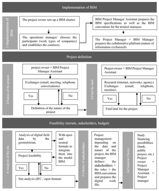
Figure 1.
Organizational models for the preliminary study.
Defining the nature of the project: the stakeholders involved are the project owner and their BIM assistant. They may exchange information via email, in meetings, or by telephone. If they successfully define the project, they will proceed to the next stage. If they do not succeed, they will continue to exchange information until a result is achieved, allowing them to move on to the next activity.
Finding a suitable site: the stakeholders involved are the project owner and their BIM assistant. They will search for a compatible site through the internet, within their agencies, or via their contacts, with discussions taking place through email, meetings, or telephone calls. If they find a compatible site, they will send all relevant information to the surveyor. If they do not find a suitable site, they will continue their research and discussions until a compatible site is located.
Terrain analysis: the surveyor analyzes the terrain using open, neutral formats to integrate it into the digital model, then sends the terrain analysis to the project manager in IFC format.
Choosing the stakeholders: based on the data and the nature of the project, the project manager identifies the stakeholders and defines their roles. The BIM manager then drafts the BIM convention and prepares the digital work file.
The financial decision: the project owner and their BIM assistant meet to explore the financing options for the project. If it is a large project, they may require the involvement of the project manager or may need his approval to secure financing through a bank.
4.4.2. Programming
The first three levels of collaboration during the programming phase according to Briggs are shown in Table 9.
Table 9.
The application of Briggs’ first three levels of collaboration to the programming phase.
The first level of collaboration (goal): the goal of this phase is to define a program of spaces.
The second level of collaboration (product): the product produced by the stakeholders without BIM is to create a program with the project’s spaces and surfaces, whereas, with BIM, all the information must be integrated into a level-zero digital model.
Before moving on to the third level, which involves defining the activities, the stakeholders who will be involved have been identified:
- Without BIM: the owner and his assistant, the geometer, and the project management team (architect, programmer, sociologist, engineers);
- With BIM: the client and his BIM assistant, the geometer (exchange in IFC), and the project management team (BIM Manager, architect (exchange in IFC), engineers (exchange in IFC), programmer, sociologist, etc.).
The third level of collaboration (activities):
- Without BIM: functional programming and detailed technical programming;
- With BIM: the stakeholders working on this phase will have to carry out the same activities as they would have done without BIM, but they will have to enter all the information in a digital file.
Organizational Model of the Work of the Stakeholders Involved in Programming
Now that the three levels of collaboration have been defined, the activities will now be described which are undertaken to determine the role of each stakeholder and to propose the organizational model (Figure 2).
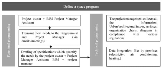
Figure 2.
Organizational models for the programming phase.
Functional programming: The project owner, with the assistance of their BIM assistant, communicates their requirements to the project manager either by email or during a meeting. Together, they develop a set of specifications that quantify the owner’s needs.
Technical programming: The project manager collects all the relevant information, including urban and architectural challenges and surface area requirements. They then create flowcharts and diagrams and integrate all the data into the digital model file.
4.4.3. Sketch Phase
Table 10 shows the first three levels of collaboration according to Briggs’ model during the sketch phase.
Table 10.
The application of Briggs’ first three levels of collaboration to the sketch phase.
The first level of collaboration (goal): the goal of this phase is to have a validated sketch of the project.
The second level of collaboration (product): the products produced by the stakeholders without BIM are a feasibility study and a sketch complying with the programme; in the case of the project with BIM, all the information must be integrated into a LOD 100 digital model.
Before moving on to the third level, which involves detailing the activities, the stakeholders who will be involved must be identified:
- Without BIM: the project owner and his assistant, the programmer, and the project management team (architect, engineer, landscape architect, economist, etc.);
- With BIM: the project owner and his BIM assistant, the programmer (exchange in IFC), and the project manager, as well as the BIM architect (exchange in IFC), engineers (exchange in IFC), and BIM coordinator.
The third level of collaboration (activities):
- Without BIM: carry out a structural and financial feasibility study of the project to draw up a 1/500 principle plan (diagram), a 1/500 functional and spatial diagram/scheme, and a 1/200 sketch.
- With BIM: the stakeholders who will be working on this phase will have to carry out the same activities as they would have done without BIM, but they will have to enter all the information into a LOD 100 digital model.
Organizational Model of the Work Carried out by the Stakeholders During the Sketching Phase
Now that the three levels of collaboration have been defined, the activities will be presented to identify the role of each stakeholder and suggest the organizational model shown in Figure 3.
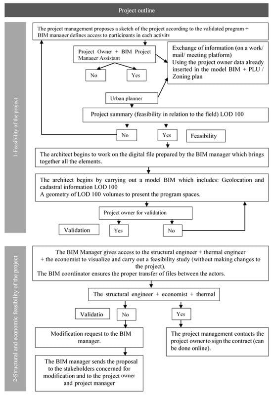
Figure 3.
Organizational models for the sketch phase.
Project feasibility: once the project owner has approved the sketch, the project team (architect and town planner) begins exchanging information on the work platform through email and meetings. They use the project owner’s data already inserted into the digital model, based on the local urban plan (PLU), to conduct a feasibility study of the project concerning the site. If the project is deemed not feasible (as indicated in the diagram), the project owner is informed so that revisions can be made. If the feasibility is validated, the architect begins working on the digital file prepared by the BIM manager, which consolidates all the necessary elements. The architect then creates the digital model, including geolocation and cadastral information (LOD 000), and a basic geometry of the volumes (LOD 100) to present the spaces in the program.
Structural and economic feasibility of the project: once the model has been produced, the project owner grants permission for the BIM manager to open access to the structural engineer, the economist, and the heating engineer. These stakeholders can then view the model and conduct a feasibility study (without making any changes to the project) with the assistance of the BIM coordinator, who ensures that the files are correctly transferred between the stakeholders.
4.4.4. APS Preliminary Design Phase
Table 11 presents the first three levels of collaboration according to Briggs’ model at the preliminary design stage.
Table 11.
The application of Briggs’ first three levels of collaboration to the preliminary design phase.
The first level of collaboration (“goal”): the goal of this sub-phase is to have a more detailed project in LOD 200 (surface area, space, opening).
The second level of collaboration (product): the products produced by the stakeholders without BIM are the graphic file and schedule, a financial estimate, and a confirmation of feasibility, whereas, with BIM, all the information must be integrated into a digital model of LOD 200.
Before moving on to the third level of activities, the stakeholders who will be involved must be identified:
- Without BIM: the project owner and his assistant, the programmer, and the project management team (architect, engineer, landscape architect, economist, etc.);
- With BIM: the project owner and his BIM assistant, the programmer (exchange in IFC), and the project management team (BIM architect (exchange in IFC), engineer (exchange in IFC), BIM coordinator).
The third level of collaboration (activities):
- Without BIM: the graphic file (plan/facade) (scale: 1/200) and the perspectives 1/200, the schedule, and then a financial estimate and confirmation of feasibility.
- With BIM: The stakeholders who will be working on this phase will have to carry out the same activities as they would have done without BIM, but they will have to enter all the information on a LOD 200 digital model.
Organizational Model of the Work of the Stakeholders During the Preliminary Design Phase
With the three levels of collaboration identified, the activities will now be described which are undertaken to determine the role of each stakeholder and suggest the organizational model shown in Figure 4.
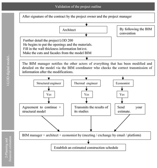
Figure 4.
Organizational models for the preliminary design phase.
Digital model: once the contract has been signed and the project owner has given approval, the architect proceeds to detail the project in the LOD 200 model by placing apertures, defining materials, filling in information on the thicknesses of the interior and exterior walls, and creating sections and facades based on the digital model. The BIM manager then notifies the other stakeholders of all modifications and details added to the model, allowing them to review, approve, and submit their respective contributions.
Planning and financial estimate: the BIM manager, in collaboration with the architect and the economist, prepares the construction schedule through meetings, email exchanges, and the platform. This schedule is then presented to the project owner along with all relevant elements, including the model, surface area of the spaces, planning, and financial estimate.
4.4.5. Detailed Preliminary Design
Table 12 shows the first three levels of collaboration according to Briggs’ model during the detailed preliminary design phase.
Table 12.
The application of Briggs’ first three levels of collaboration to the detailed preliminary design phase.
The first level of collaboration (objective): the objective of this phase is to detail the project for the permit application.
The second level of collaboration (product): the product produced by the stakeholders without BIM is the graphic file 1/100 and 1/50, but with BIM all the information must be integrated into a digital model of LOD 200.
Before moving on to the third level, which involves detailing the activities, the stakeholders who will be involved must be identified:
- Without BIM: the project owner and his assistant, the programmer, and the project management team (architect, engineer, landscape architect, economist, etc.);
- With BIM: the project owner and his BIM assistant, the programmer (exchange in IFC), and the project management team (BIM architect (exchange in IFC), engineer) exchange in IFC), BIM coordinator).
The third level of collaboration (activities):
- Without BIM: creation of a detailed plan with a 1/100 and 1/50 structure with pre-dimensions, then a layout of the systems (electricity, ventilation, heating, plumbing), a table of surface areas, and an estimate of the final cost;
- With BIM: the stakeholders working on this phase will have to carry out the same activities as they would have done without BIM, but they will have to enter all the information on a LOD 200 digital model with the structural model superimposed on the foundations and the definition of all the materials with their characteristics.
Organizational Model for the Work of the Stakeholders During the Detailed Preliminary Design Phase
After defining the three levels of collaboration, the activities will now be described which are undertaken to determine the role of each stakeholder and to propose the organizational model shown in Figure 5.
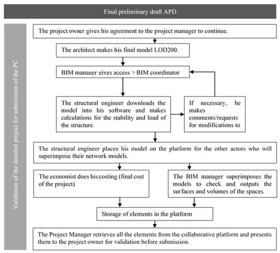
Figure 5.
Organizational models for the detailed preliminary design phase.
Digital model: after the project owner gives approval to the project manager to proceed with the digital model, the BIM manager grants access to the architect to finalize their part and provides access to the engineers to overlay their models.
The structural engineer uploads the model into their software to calculate the stability and load of the structure, making any necessary comments or requesting modifications from the architect. Once the structural engineer has completed their part, they upload it onto the platform, allowing the other engineers to overlay their models of the various systems. After this, the economist carries out the final pricing of the project. The BIM manager then overlays the models from the various stakeholders to verify the surface areas and volumes of the spaces before presenting the complete model to the project owner.
4.4.6. Construction Permits
Table 13 shows the first three levels of collaboration according to Briggs’ model during the construction permit phase.
Table 13.
The application of Briggs’ first three levels of collaboration to the construction permit phase.
The first level of collaboration (“goal”): the goal of this phase is to submit the file to the town hall.
The second level of collaboration (product): the products produced by the stakeholders without BIM are the 1/100- and 1/50-scale graphic files, the Bbio attestation, and the completed Cerfa3 document; with BIM, all the information must be integrated into a LOD 200 digital model, as well as the Cerfa document and the Bbio attestation.
Before moving on to the third level, which involves detailing the activities, the stakeholders who will be involved must be identified:
- Without BIM: the project owner and the project manager;
- With BIM: the project owner and the prime contractor.
The third level of collaboration (activities):
- Without BIM: graphic file (plan/facade/cuts) (1/100 and 1/50), with the 3D rendering for insertion, Bbio attestation, and Cerfa to be filled in.
- With BIM: the stakeholders working on this phase will have to carry out the same activities as they would have done without BIM, but they will have to enter all the information on a digital LOD 200 model and generate the Bbio attestation from the thermic engineer’s calculations.
Organizational Model of Stakeholder Work During the Construction Permit Application Process
After defining the three levels of collaboration, the activities will now be described to determine the role of each stakeholder and to propose the organizational model shown in Figure 6.
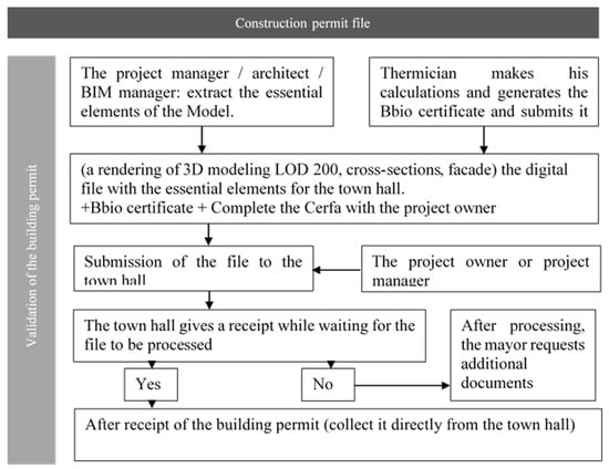
Figure 6.
Organizational models for the construction permit phase.
Digital model: the project manager extracts the essential elements from the model, such as cross-sections, facades, and 3D renderings. These, along with the digital file containing the essential elements for the town hall and the thermal engineer’s calculations (Bbio attestation), are prepared. The project owner then completes the necessary document (Cerfa form for the project) and submits it to the town hall.
While waiting for the construction permit, the mayor’s office may request additional documents.
5. Discussion
This study aimed to address the issue of inadequate collaboration and communication among stakeholders in construction projects through the use BIM. By defining the roles and access of stakeholders to the BIM model, this study sought to clarify the interactions and the timing of various project phases. The ultimate goal was to propose organizational models tailored to BIM implementation, based on the three levels of collaboration outlined in Briggs’ model [16].
The findings demonstrate that applying these three levels of collaboration (objectives, products, activities) effectively modeled stakeholder interactions and identified key points of collaboration. This approach combined both practical and organizational dimensions, offering a more comprehensive view of project management in a BIM context. This integration not only facilitates communication among stakeholders but also reduces errors and misunderstandings that are common in construction projects.
The proposed organizational models provide a clear roadmap for construction agencies, particularly during the design phase. By structuring the roles and responsibilities of each stakeholder, these models enhance coordination and ensure that tasks are completed on time with accurate information given. This approach is especially relevant for large-scale projects, where complexity and the number of stakeholders increase the risk of dysfunction. Additionally, centralizing data and increasing ease of access to the BIM model ensures that all participants have the necessary information to make informed decisions, thereby improving the efficiency of the design process.
Despite the contributions of this research, certain limitations must be acknowledged. Firstly, this study focused primarily on the design phase of architectural projects, leaving out the specific challenges of the construction and operation phases. Furthermore, while the proposed models are based on rigorous analysis, their applicability may vary depending on the specific context of each project, particularly in terms of local regulations and architectural practices. Lastly, the generalizability of the results might be limited, as the scenarios studied do not encompass all types of projects or national contexts.
There are numerous avenues for future research. One promising direction would be to develop organizational models for the construction and operation phases, thereby completing the guide proposed in this study. Additionally, real-world case studies could be conducted to validate the models in different contexts and refine the proposals based on user feedback. The application of the other four levels of collaboration from Briggs [16] could also be explored to further model stakeholder activities and ensure effective collaboration.
In conclusion, this study highlights the importance of clearly defining the roles and access of stakeholders in construction projects using BIM. The organizational models developed herein provide a practical framework for improving collaboration and communication, which are crucial to the success of these projects. By advocating for the wider adoption of these practices within the industry, this research paves the way for new approaches to project management in a BIM context, with opportunities for continuous improvement through future research.
6. Conclusions
The application of a collaborative engineering method has allowed us to propose organizational models for the work of construction stakeholders during the design phase of a BIM architectural project. The objective of the proposed organizational model is to simplify the concept of BIM from a practical standpoint and to facilitate its implementation in agencies by structuring the work of construction stakeholders. Our aim is to clarify when it is mandatory to intervene, what actions need to be taken, and with whom these actions should be coordinated.
These models will serve as manuals for each construction stakeholder during the design phase. In our future research, we plan to develop models for the remaining two project stages (construction and operation), with the goal of creating a comprehensive guide for the introduction and implementation of BIM in agencies.
Author Contributions
Validation, H.A.H. and G.C.; investigation, H.R.; resources, H.R., H.A.H. and G.C.; data curation, H.R.; writing—original draft preparation, H.R.; writing—review and editing, G.C. and H.A.H.; visualization, G.C. and H.R.; supervision, H.A.H. and G.C.; project administration, H.A.H., G.C. and H.R. All authors have read and agreed to the published version of the manuscript.
Funding
This research received no external funding.
Institutional Review Board Statement
Not applicable.
Informed Consent Statement
Not applicable.
Data Availability Statement
The original contributions presented in this study are included in the article. Further inquiries can be directed to the corresponding author.
Acknowledgments
This article benefited from the use of artificial intelligence IA tools (ChatGPT and QuillBot), for assistance with text reformulation and translation. Their use was limited to improving linguistic clarity.
Conflicts of Interest
The authors declare no conflict of interest.
Notes
| 1 | BuildingSMART France—Mediaconstruct is a 1901 association that plays a national and international role in promoting BIM and thus supports the digital transition of construction towards good openBIM work practices. |
| 2 | IFC, or “Industry Foundation Classes”, is a standardized digital description of the built environment, such as buildings and civil infrastructure. It’s an open, international standard (ISO 16739-1:2018) designed to be neutral and compatible with various hardware and software platforms. |
| 3 | A Cerfa form refers to a regulated administrative document, defined by a decree that sets the model, used to obtain administrative documents. |
References
- ISO 19650-1; Organization and Digitization of Building and Civil Engineering Information, Including Building Information Modelling (BIM)—Information Management Through Building Information Modelling—Part 1: Concepts and Principles. ISO: Geneva, Switzerland, 2018. Available online: https://www.iso.org/obp/ui/#iso:std:iso:19650:-1:ed-1:v1:fr (accessed on 26 May 2023).
- BIM Glossary from BuildingSMART France, Association of BIM Stakeholders in France. 26 March 2019. Available online: https://buildingsmartfrance-mediaconstruct.fr/glossaire-bim-bsfrance/ (accessed on 15 December 2021).
- National Institutute of Building Science. National Building Information Modeling Standard Version 1—Part 1: Overview, Principles, and Methodologies; National Institutute of Building Science: Washington, DC, USA, 2007. [Google Scholar]
- Abualdenien, J.; Borrmann, A. Levels of detail, development, definition, and information need: A critical literature review. J. Inf. Technol. Constr. 2022, 27, 363–392. [Google Scholar] [CrossRef]
- Celnik, O.; Lebègue, É. BIM et Maquette Numérique pour L’architecture, le Bâtiment et la Construction, 2nd ed.; Paris Marne-la-Vallée: Eyrolles CSTB éditions, 2015. Available online: https://www.eyrolles.com/BTP/Livre/bim-et-maquette-numerique-9782212142747/ (accessed on 15 November 2021).
- Hochscheid, É.; Halin, G. L’adoption du BIM dans les agences d’architecture en France. SHS Web Conf. 2018, 47, 01009. [Google Scholar] [CrossRef]
- McGraw Hill Construction. Adding Value to Construction with BIM in Major Global Markets: How Prime Contractors around the World are Innovating with Building Information Modeling (BIM), McGraw Hill Construction, Research & Analytics 34 Crosby Drive, Suite 201 Bedford, MA 01730, USA, 2014. Available online: https://damassets.autodesk.net/content/dam/autodesk/files/fy15-q1-aec-btt-const-bim-report-fr.pdf (accessed on 26 January 2022).
- PTNB. PTNB-Bilan-Rapport Final 2018, Vol. Plan Transition Numérique dans le Bâtiment—BILAN-, p. 68, December 2018. Available online: https://www.ecologie.gouv.fr/sites/default/files/documents/Bilan%202018%20PTNB.pdf (accessed on 17 April 2024).
- Cegibat, G. Enquête sur la Pratique du BIM par les Bureaux D’études, Cegibat.fr. Available online: https://cegibat.grdf.fr/actualites/enquete-pratique-bim-bureaux-etudes (accessed on 1 November 2021).
- Hochscheid, E.; Halin, G. Baromètre BIM: Une Enquête sur L’adoption du BIM Dans les Agences D’architecture en France. In Proceedings of the SCAN’20 Séminaire de Conception Architecturale Numérique, Brussels, Belgium, 16–20 November 2020. [Google Scholar]
- Ghiasi, S.H.B.; Oyarhossein, M.A.; Khiali, V. Identifying Barriers of Implementing BIM in Construction. Technium 2021, 3, 9–20. [Google Scholar] [CrossRef]
- Briggs, R.; Kolfschoten, G.; de Vreede, G.-J.; Dean, D. Defining Key Concepts for Collaboration Engineering. In Proceedings of the Conférence Internationale sur les Systèmes D’information, AMCIS 2006, États-Unis, Acapulco, Mexico, 4–6 August 2006; pp. 121–128. [Google Scholar]
- De Vreede, G.-J.; Briggs, R.; Massey, A. Collaboration Engineering: Foundations and Opportunities: Editorial to the Special Issue on the Journal of the Association of Information Systems. J. Assoc. Inf. Syst. 2009, 10, 121–137. [Google Scholar] [CrossRef]
- Joss, F.; Rinquet, L.; Domer, B. Management du Projet de Construction: Un Vadémécum D’économie, de Droit et de Planification pour le Bâtiment, 1st ed.; PPUR: Lausanne, Switzerland, 2017. [Google Scholar]
- De Vreede, G.-J.; Briggs, R. Collaboration Engineering: Reflections on 15 Years of Research & Practice. In Proceedings of the 51st Hawaii International Conference on Systems Science, Hilton Waikoloa Village, HI, USA, 3–6 January 2018. [Google Scholar] [CrossRef]
- Briggs, R.; Kolfschoten, G.; de Vreede, G.-J.; Albrecht, C.; Dean, D.; Lukosch, S. A Seven-Layer Model of Collaboration: Separation of Concerns for Designers of Collaboration Systems. In Proceedings of the 30th International Conference on Information Systems, ICIS 2009, Phoenix, AR, USA, 15–18 December 2009; p. 26. [Google Scholar]
- Fernandez, P.; Lavigne, P. Concevoir des Bâtiments Bioclimatiques: Fondements & Méthodes; Moniteur: Paris, France, 2009. [Google Scholar]
- INRS. Conception des Lieux et des Situations de Travail. Démarche de Conception et Prévention—Démarches de Prévention—INRS. Available online: https://www.inrs.fr/demarche/conception-lieux-situations-travail/demarche-conception-prevention.html (accessed on 5 October 2021).
- Les Etapes d’un Projet RT2012. INEX. Available online: https://www.inex.fr/ingenierie-thermique-et-environnementale/expertise-energetique/etude-reglementaire-rt-2012/les-etapes-dun-projet-rt2012/ (accessed on 5 October 2021).
- CAUE92, Tableau Acteurs et Etapes de la Conception et de la Construction. 2018. Available online: https://www.caue92.fr/atelier-pedaifcgogique/ressources/outils-specifiques-ecole-en-chantier (accessed on 5 October 2021).
- CHARTE BIM DE LA SOCIÉTÉ DU GRAND PARIS.pdf. Available online: https://media-mediatheque.societedugrandparis.fr/medias/domain1/media559/84396-81qtc2ijro.pdf (accessed on 10 November 2017).
- Hoyet, N.; Duchene, F.; de Fouquet, M. BIM and Architecture: Programming, Design, Construction, Operation; Dunod: Malakoff, France, 2016. [Google Scholar]
- Jupp, J. 4D BIM for Environmental Planning and Management. Procedia Eng. 2017, 180, 190–201. [Google Scholar] [CrossRef]
Disclaimer/Publisher’s Note: The statements, opinions and data contained in all publications are solely those of the individual author(s) and contributor(s) and not of MDPI and/or the editor(s). MDPI and/or the editor(s) disclaim responsibility for any injury to people or property resulting from any ideas, methods, instructions or products referred to in the content. |
© 2025 by the authors. Licensee MDPI, Basel, Switzerland. This article is an open access article distributed under the terms and conditions of the Creative Commons Attribution (CC BY) license (https://creativecommons.org/licenses/by/4.0/).