
A Review of Collaborative Virtual Reality Systems for the Architecture, Engineering, and Construction Industry


Abstract
:1. Introduction
1.1. Background
1.2. Advantages and Disadvantages of VR
1.2.1. Advantages
- (a)
- Interactivity: users can interact with models;
- (b)
- Spatiality: models are represented in three spatial dimensions;
- (c)
- Immediacy: real-time feedback from actions is given without noticeable pause;
1.2.2. Disadvantages
2. Existing VR Solutions for the AEC Industry
2.1. Existing VR Solutions
2.2. Comparison
- (1)
- Scope: which phase of the project they target, and which discipline(s);
- (2)
- Broadness: how many disciplines they can target;
- (3)
- Features: the most important features available;
- (4)
- Multi-user capability: for real-time collaboration;
- (5)
- Design capability: to design at vertice level (not just simple affine transformations);
- (6)
- Texture support: support textures rather than only simple colors;
- (7)
- Interconnectivity: how they are interconnected to other software.
2.3. Interconnection Solutions
3. Proposing a System for Multi-Disciplinary Collaboration in VR
3.1. UIs Guidelines
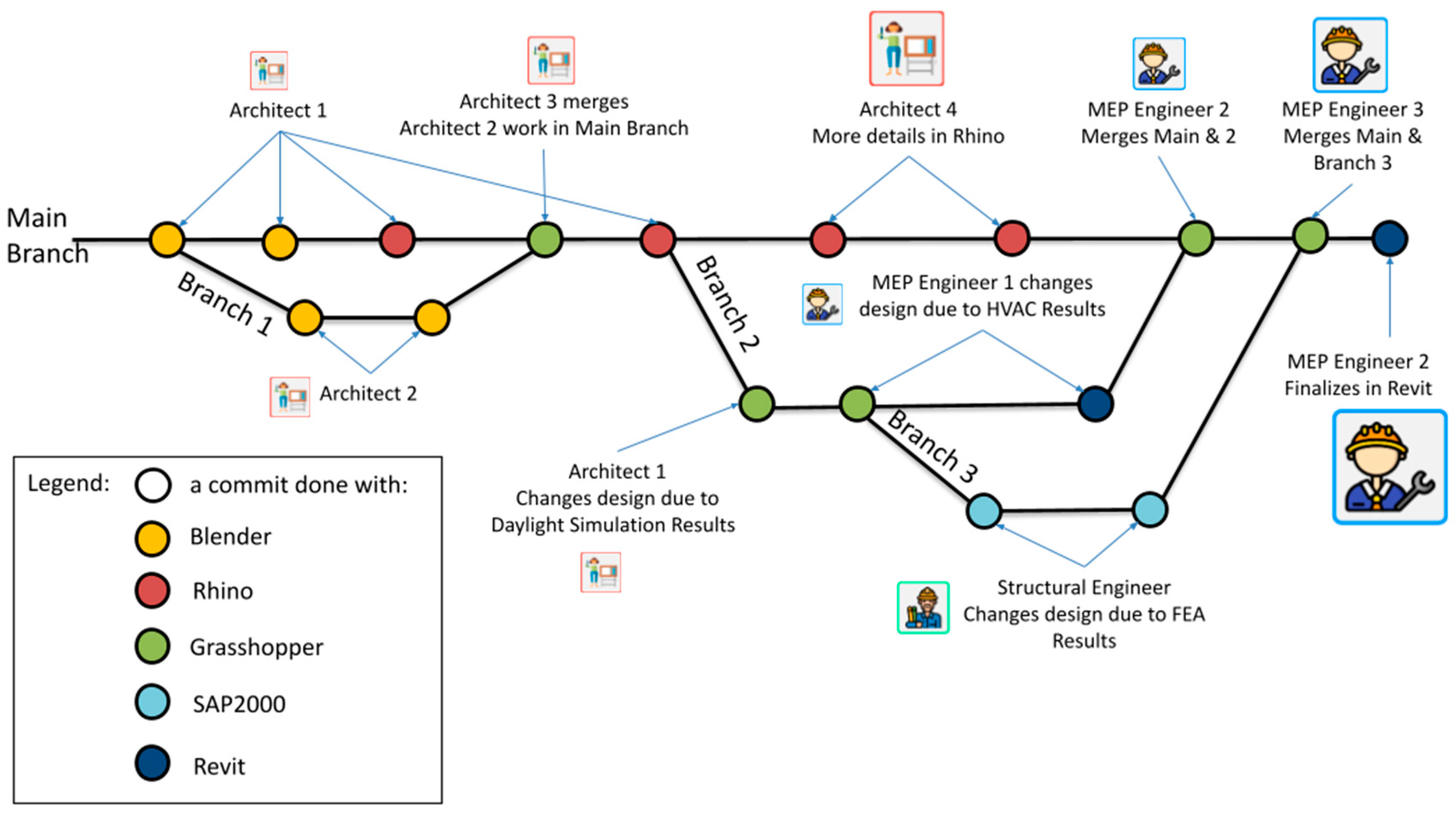
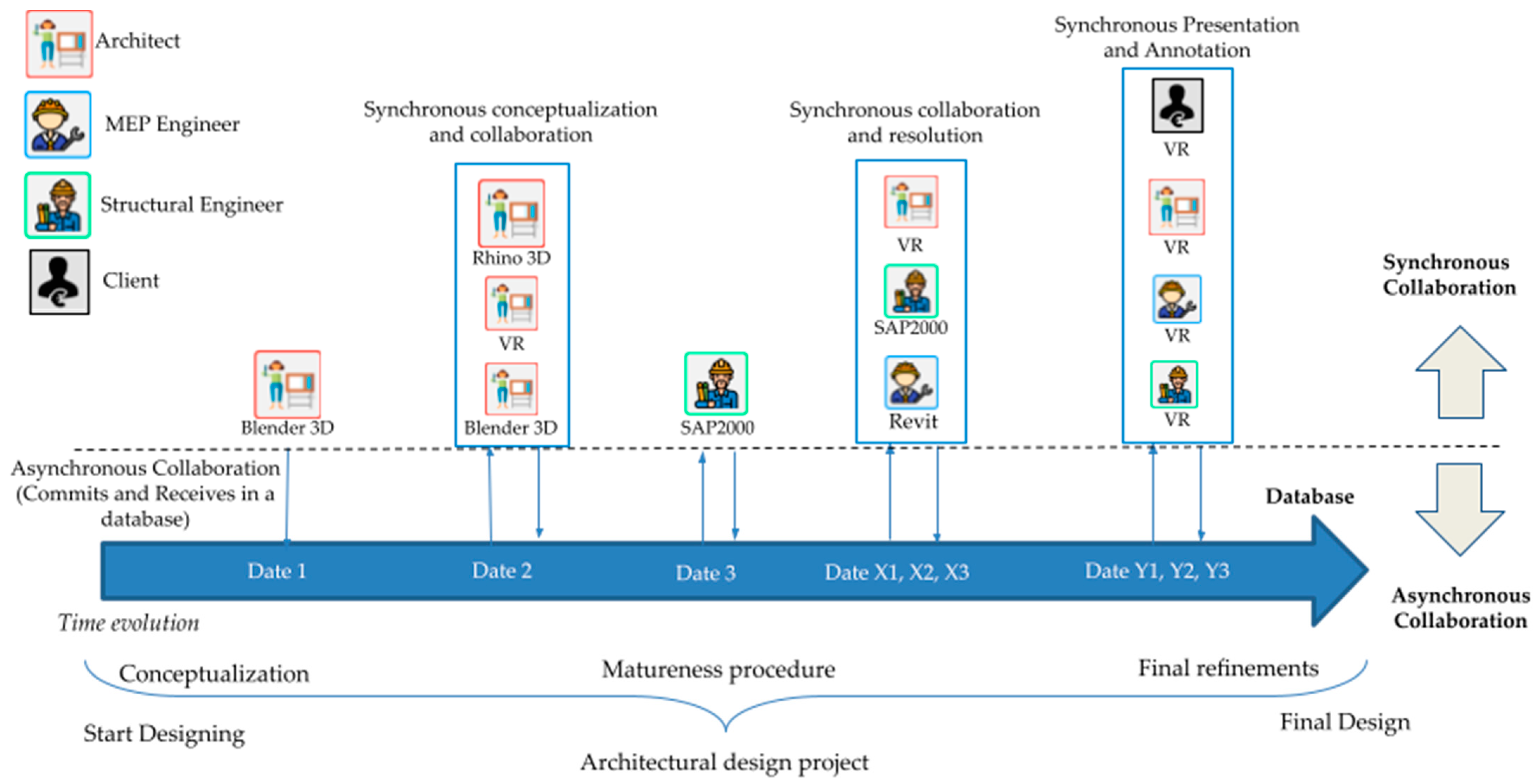
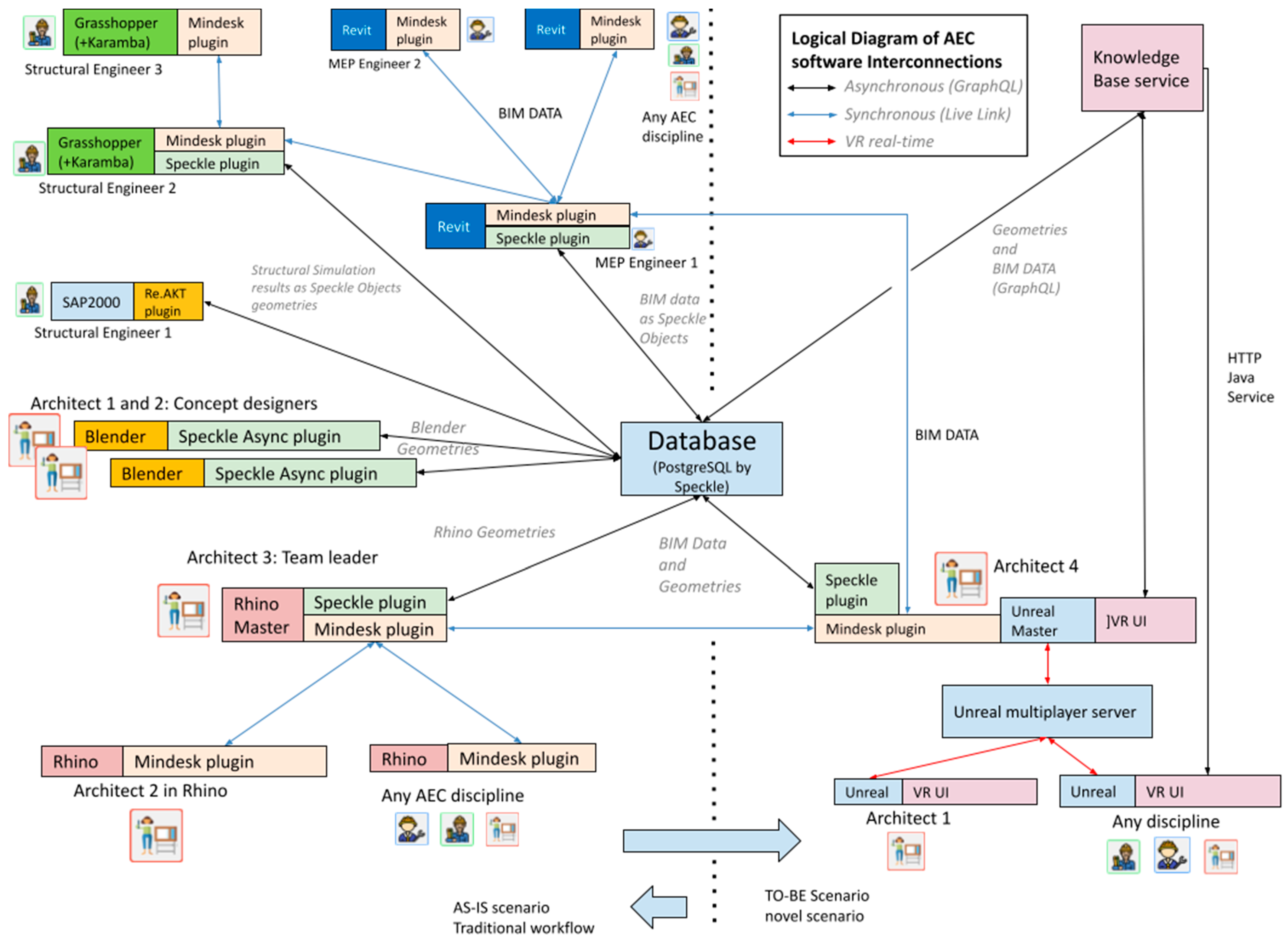
3.2. Optimum Interconnection and Collaboration Schema
3.3. Establishing a Theoretical Framework for Collaborative Design
3.4. Implementation Pathway
4. Conclusions, Discussion, and Future Work
Author Contributions
Funding
Institutional Review Board Statement
Informed Consent Statement
Acknowledgments
Conflicts of Interest
Abbreviations
| AEC | Architecture, Engineering and Construction |
| API | Application Programming Interface |
| BHoM | Buildings and Habitats object Model |
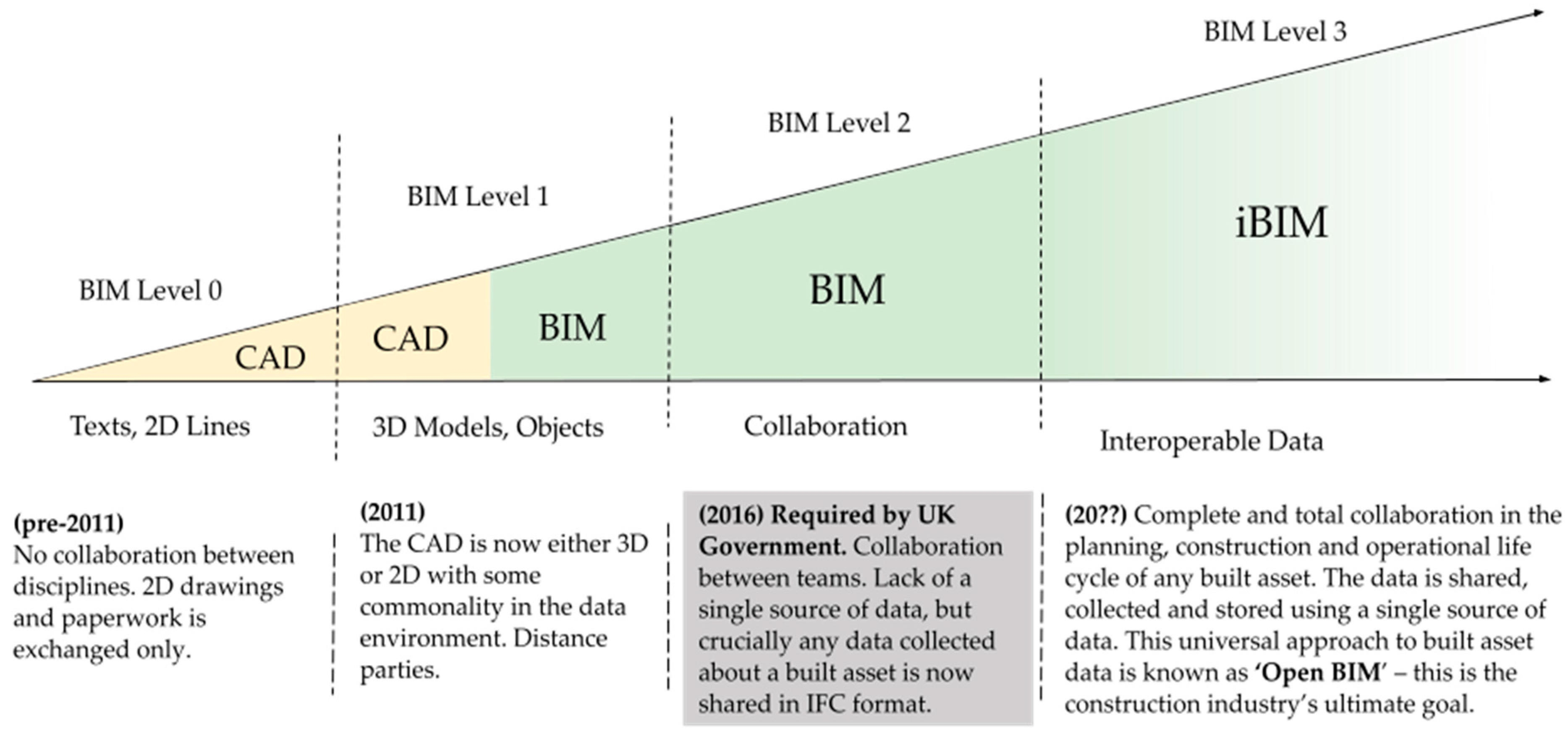
| BIM | Building Information Modeling |
| CAD | Computer-Aided Design |
| CAE | Computer-Aided Engineering |
| FEM | Finite Element Modeling |
| GA | Grant Agreement |
| HTTP | Hypertext Transfer Protocol |
| IBC | International Building Code |
| IFC | Industry Foundation Classes |
| MEP | Mechanical, Electrical, and Plumbing |
| REST API | Representational State Transfer Application Programming Interface |
| TCP | Transmission Control Protocol |
| UI | User Interface |
| VR | Virtual Reality |
| XR | Extended Reality |
References
- Zaker, R.; Coloma, E. Virtual reality-integrated workflow in BIM-enabled projects collaboration and design review: A case study. Vis. Eng. 2018, 6, 4. [Google Scholar] [CrossRef] [Green Version]
- Varjo. Head Mounted Display for Virtual and Augmented Reality Training Applications. Available online: https://varjo.com/ (accessed on 15 December 2021).
- Noghabaei, M.; Heydarian, A.; Balali, V.; Han, K. Trend Analysis on Adoption of Virtual and Augmented Reality in the Architecture, Engineering, and Construction Industry. Data 2020, 5, 26. [Google Scholar] [CrossRef] [Green Version]
- Computer Integrated Construction Research Program. BIM Planning Guide for Facility Owners, 2nd ed.; The Pennsylvania State University: Pennsylvania, PA, USA, 2013. [Google Scholar]
- Kim, H.; Anderson, K.; Lee, S.; Hildreth, J. Generating construction schedules through automatic data extraction using open BIM (building information modeling) technology. Autom. Constr. 2013, 35, 285–295. [Google Scholar] [CrossRef]
- Robert, E.; Tim, M.; Adam, P. An investigation into the legal issues relating to building information modeling (BIM). In Proceedings of the RICS COBRA AUBEA 2015, Sydney, Australia, 8–10 July 2015. [Google Scholar]
- Badamasi, A.A.; Aryal, K.R.; Makarfi, U.U.; Dodo, M. Drivers and barriers of virtual reality adoption in UK AEC industry. Eng. Constr. Archit. Manag. 2021, 29, 1307–1318. [Google Scholar] [CrossRef]
- Arkio Collaborative Spacial Design: VR User Experience. Available online: https://www.youtube.com/watch?v=zc1UcBa-Q7o (accessed on 18 March 2022).
- Twinmotion, Virtual Reality for Architecture with Twinmotion—Webinar. Available online: https://www.youtube.com/watch?v=NvCjWUgqCXk, (accessed on 21 March 2022).
- 3DRepo, The Digital Twin Platform for BIM Data. Available online: https://github.com/3drepo/3drepo.io (accessed on 22 March 2022).
- Brösamle, M.; Mavros, P.; Hölscher, C. Report of Cognitive Issues in VR-Aided Design Environments and Usability Guidelines. PrismArch Project Technical Report D3.1. 2022. Available online: https://prismarch-h2020.eu/download/472 (accessed on 7 June 2022).
- Goulding, J.S.; Rahimian, F.P.; Wang, X. Virtual reality-based cloud BIM platform for integrated AEC projects. In ITcon Journal Information Technology in Construction, Special Issue BIM Cloud-Based Technology in the AEC Sector: Present Status and Future Trends; CASPA Publisher: Lismore, Australia, 2014; pp. 308–325. Available online: https://www.itcon.org/2014/18 (accessed on 7 June 2022).
- UK Ministry of Housing, Communities and Local Government. Draft Building Safety Bill: Forward Reforms to the Building and Fire Safety System; UK Ministry of Housing, Communities and Local Government: London, UK, 2020; ISBN 978-1-5286-2088-8. Available online: https://www.gov.uk/government/publications/draft-building-safety-bill (accessed on 7 June 2022).
- Jose, E.; Banawi, A.; Pena, E. Evaluating the benefits of introducing “BIM” based on Revit in construction courses, without changing the course schedule. Univers. Access Inf. Soc. 2018, 17, 491–501. [Google Scholar]
- Melendez, F. Drawing from the Model: Fundamentals of Digital Drawing, 3D Modeling, and Visual Programming in Architectural Design; John Wiley & Sons: Hoboken, NJ, USA, 2019. [Google Scholar]
- Mostapha Sadeghipour, R.; Pak, M.; Smith, A. Ladybug: A parametric environmental plugin for Grasshopper to help designers create an environmentally-conscious design. In Proceedings of the 13th International IBPSA Conference, Lyon, France, 26–28 August 2013. [Google Scholar]
- Scheller, J.; Constantinou, M.C. Response History Analysis of Structures with Seismic Isolation and Energy Dissipation Systems: Verification Examples for Program SAP2000; Technical Report MCEER-99-0002; Multidisciplinary Center for Earthquake Engineering Research, University at Buffalo: Buffalo, NY, USA, 1999. [Google Scholar]
- Ait-Lamallam, S.; Yaagoubi, R.; Sebari, I.; Doukari, O. Extending the IFC Standard to Enable Road Operation and Maintenance Management through OpenBIM. ISPRS Int. J. Geo-Inf. 2021, 10, 496. [Google Scholar] [CrossRef]
- Alizadehsalehi, S.; Hadavi, A.; Huang, J.C. From BIM to extended reality in AEC industry. Autom. Constr. 2020, 116, 103254. [Google Scholar] [CrossRef]
- Mouzakis, C.; Ververidis, D.; Girao, L.M.; Patz, N.; Nikolopoulos, S.; Kompatsiaris, I. Holistic Requirements Analysis for Specifying New Systems for 3D Media Production and Promotion. Sustainability 2021, 13, 8155. [Google Scholar] [CrossRef]
- Epic Online Services, EOS. Gaming Services for Multiplaying 3D Experiences. Available online: https://dev.epicgames.com/en-US/services-games (accessed on 15 December 2021).
- Vivox Audio Communication, a Service for Multiplaying 3D Experiences. Available online: https://unity.com/products/vivox (accessed on 15 December 2021).
- Kinzler, H.; Tadauchi, R.; Zolotareva, D.; Mnich-Spraiter, A. Sphereing: A Novel Framework for Real-Time Collaboration and Co-Presence in VR ZHVR White Paper; Zaha Hadid Virtual Reality Group: London, UK, 2021. [Google Scholar] [CrossRef]
- Rafsanjani, H.N.; Nabizadeh, A.H. Towards digital architecture, engineering, and construction (AEC) industry through virtual design and construction (VDC) and digital twin. In Energy and Built Environment; Elsevier: Amsterdam, The Netherlands, 2021. [Google Scholar] [CrossRef]


| # | Name | Discipline | Type | Interoperability—I/O Formats | Features |
|---|---|---|---|---|---|
| 1 | Arkio https://www.arkio.is (accessed on 7 June 2022) | Architects (VR design) | Standalone | Import and export to Revit and Rhino in real-time. Multi-user support. | Support of VR. Real-time editing. No textures support. |
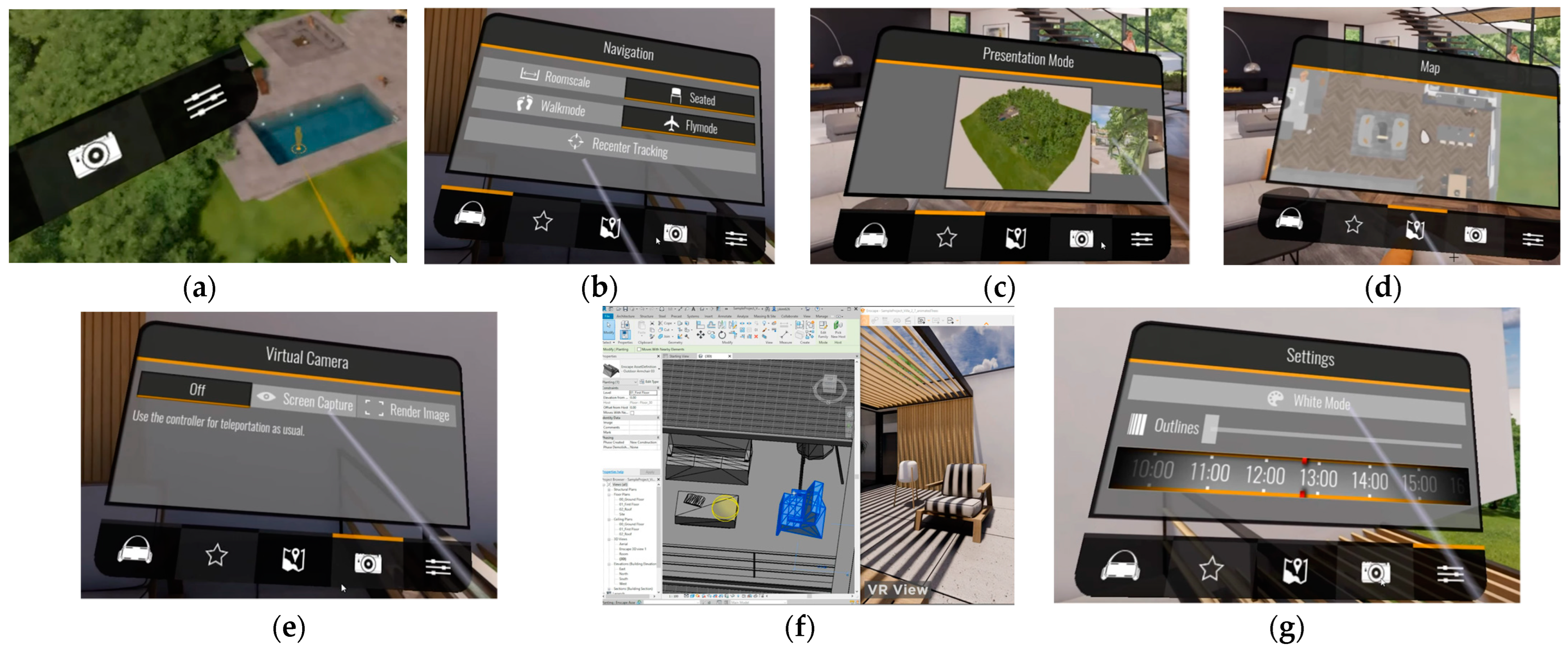
| 2 | Enscape https://enscape3d.com (accessed on 7 June 2022) | Architects (Visualization) | Standalone | Revit input, 2D graphics export for concepts. | Messaging and photorealistic rendering. |
| 3 | Fuzor https://www.kalloctech.com/ (accessed on 7 June 2022) | All Disciplines (VR and interconnection software) | Standalone | Revit and Rhino interconnect in VR. Live sync. | Integrates all disciplines into a VR environment. |
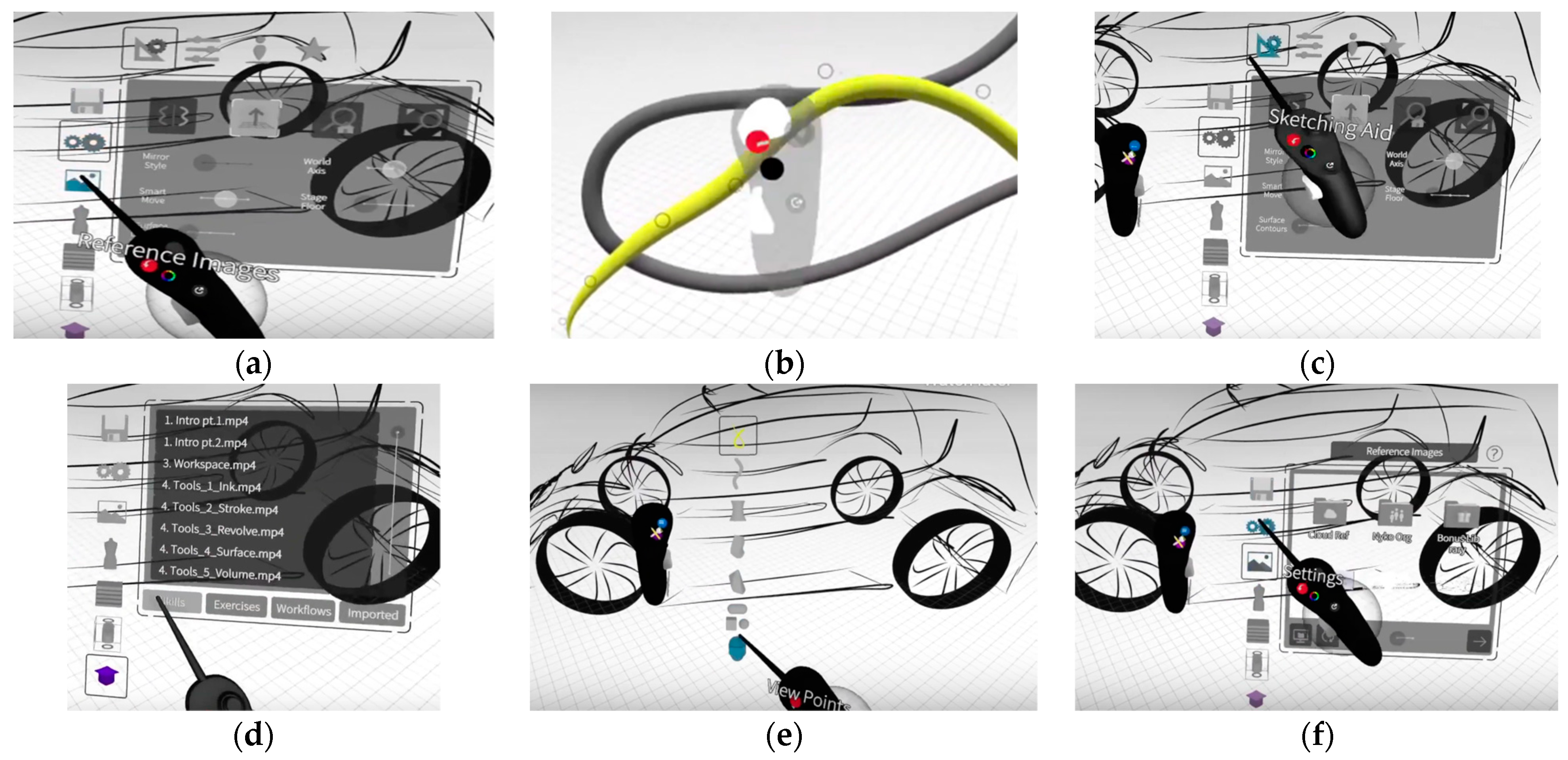
| 4 | Gravity Sketch https://www.gravitysketch.com/ (accessed on 7 June 2022) | Architects (Design in VR) | Standalone | Import and export to Rhino in real-time. | Support of VR. Real-time editing. No textures support. Multi-user. |
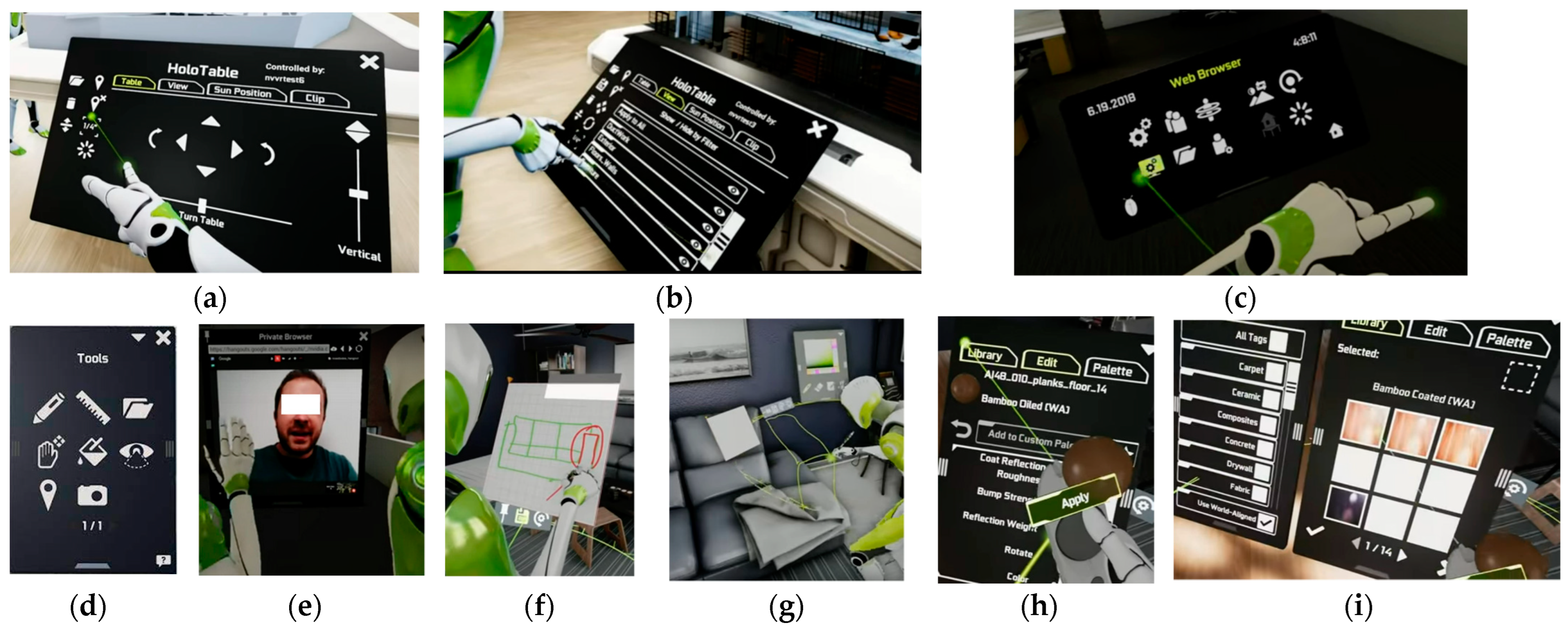
| 5 | Holodeck Nvidia www.nvidia.com/en-us/design-visualization/technologies/holodeck/ (accessed on 7 June 2022) | Architects (Design in VR) | Standalone | Import: 3Ds Max or Maya, Export: plug-in to 3Ds Max or Maya. NVidia Iray is required. | Only for standard NVIDIA vMaterials. No connection with Omniverse yet. |
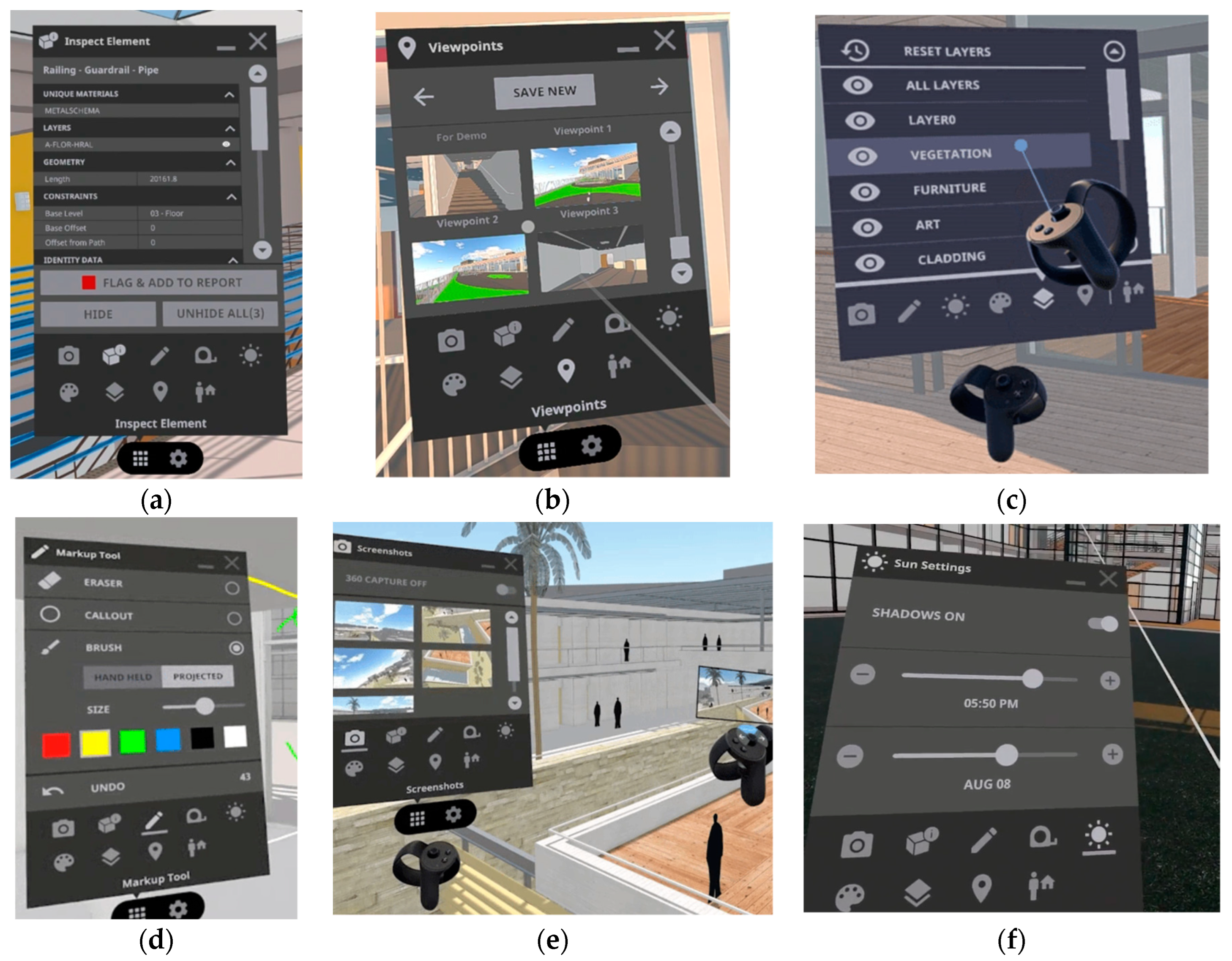
| 6 | IrisVR—The Wild https://irisvr.com/ https://thewild.com/ (accessed on 7 June 2022) | Architects (Design in VR) | Standalone | Connectors with Rhino, Revit, Navisworks, and Sketchup. | Multi-user support. |
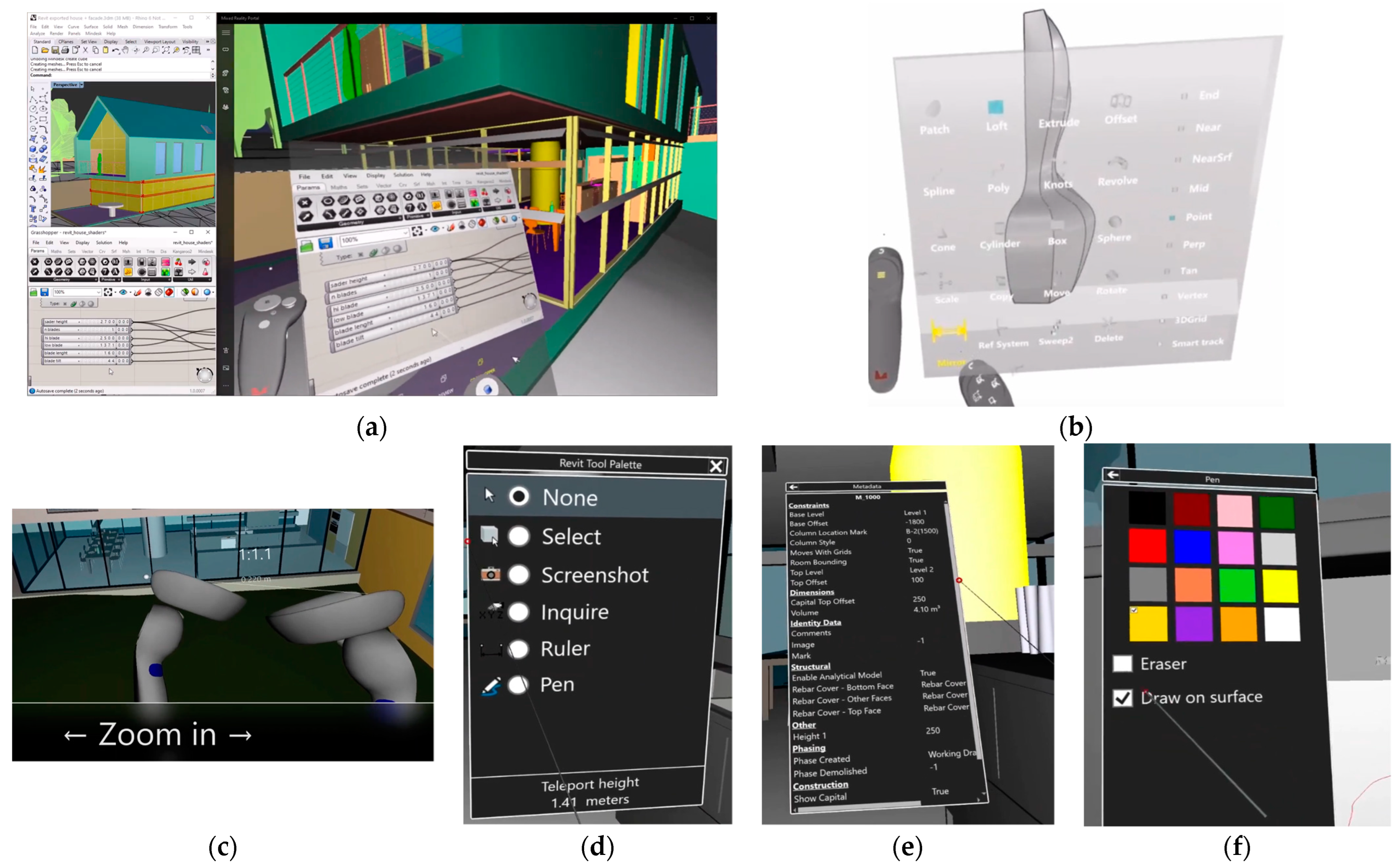
| 7 | Mindesk https://mindeskvr.com/ (accessed on 7 June 2022) | Architects (Design in VR) | Plugin | Rhino, Revit, Solidworks, and Unreal connectors. | No web interface or database support. |
| 8 | TwinMotion https://www.unrealengine.com/en-US/twinmotion (accessed on 7 June 2022) | Architects | Standalone | Improves the realism of Revit and Rhino projects. | Support for VR. Exploit real-time tracing. Change materials and add decorations. |
| Capability | |||||||
|---|---|---|---|---|---|---|---|
| Tool | 1. Scope | 2. Broadness | 3. Features | 4. Multiuser | 5. Design Capability | 6. Textures Support | 7. Interconnectivity Type |
| Arkio | Design | Architecture | Design, Nurbs, Shadows change | 🗸 | 🗸 | ✗ | File Sync, Export/Import |
| Enscape | Visualization | Architecture | Shadows change, RTX | ✗ | ✗ | 🗸 | File Sync, Export/Import |
| Fuzor | BIM, Construction | Architecture, MEP, Construction | Issue tracking, 4D construction | 🗸 | ✗ | 🗸 | Real-time with Live Link |
| Gravity Sketch | Design | Architecture | Design, Nurbs, Texturing | 🗸 | 🗸 | 🗸 | File Sync, Export/Import |
| Holodeck NVidia | Visualization | Architecture | Issues tracking, Texturing | 🗸 | ✗ | 🗸 | File Sync, Export/Import, Omniverse |
| IrisVR—The Wild | BIM | Architecture, MEP | Issues tracking, Texturing | 🗸 | ✗ | 🗸 | File Sync, Export/Import |
| Mindesk | Design, BIM | Architecture, MEP | Design, Nurbs, Issues tracking | 🗸 | 🗸 | 🗸 | Real-time with Live Link |
| TwinMotion | Visualization | Architecture | RTX, Vegetation, Shadows | ✗ | ✗ | 🗸 | File Sync, Export/Import |
| # | Name | AEC Discipline | License | Software Supported | Features |
|---|---|---|---|---|---|
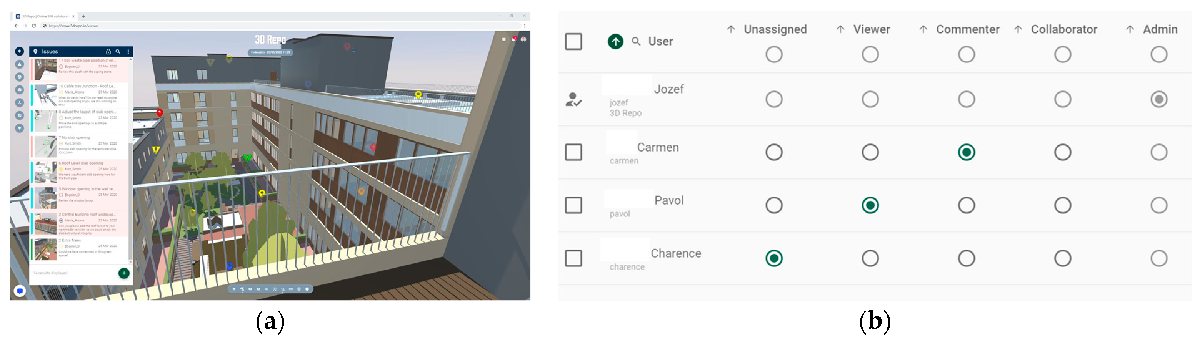
| 1 | 3D Repo https://3drepo.com (accessed on 7 June 2022) | All disciplines | AGPL3 | Revit, Navisworks, Autodesk, Civil3D, Autocad, Unity, Unreal | Clash detection, issues tracking, diffing, safety issues detection, and permissions allocation. |
| 2 | BHoM https://github.com/BHoM (accessed on 7 June 2022) | All disciplines | LGPL | Rhino, Revit, Ladybug, Excel, SAP2000, Unreal, Speckle | A communication standard across 3D software rather than a software solution. |
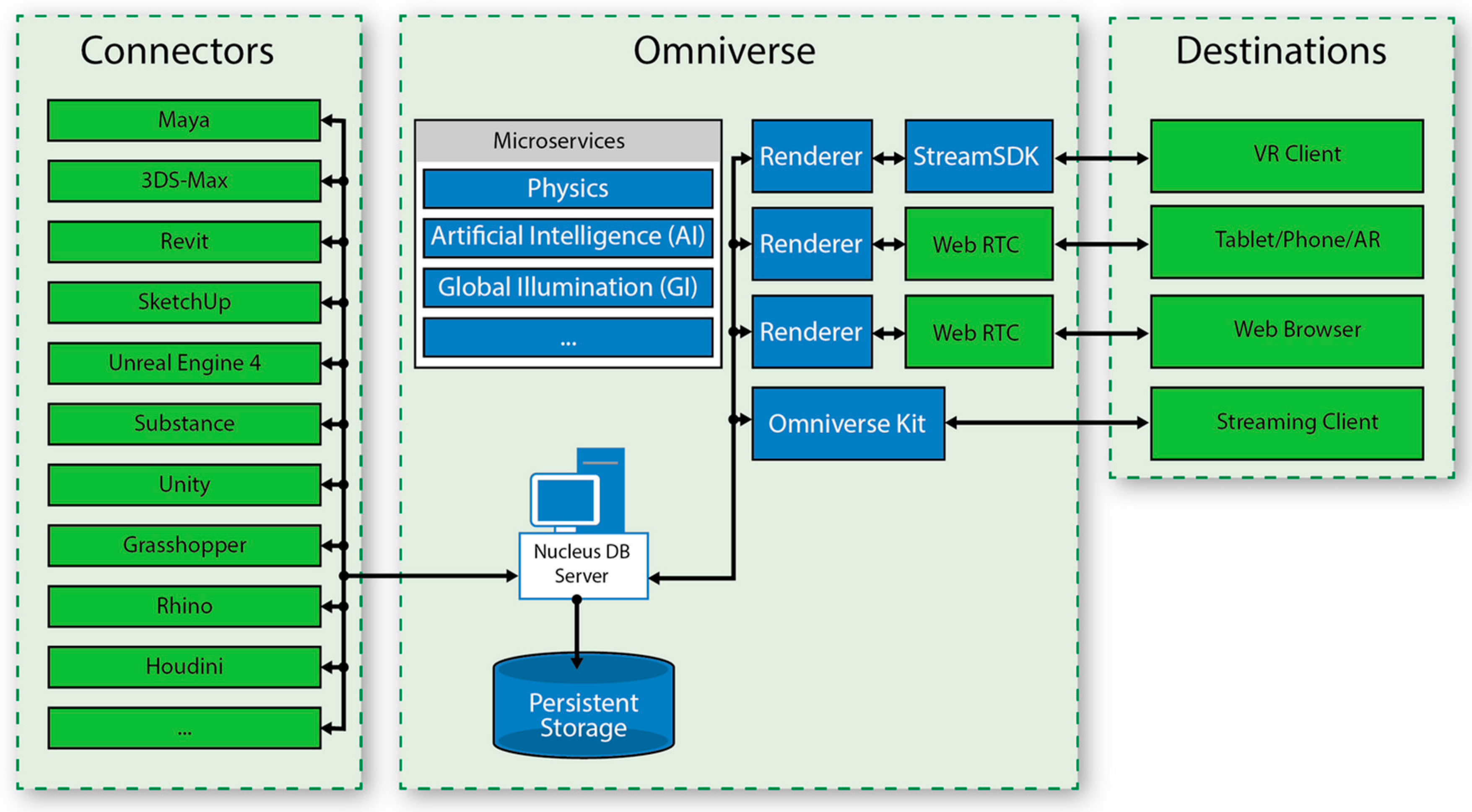
| 3 | Omniverse NVidia https://developer.nvidia.com/nvidia-omniverse-platform (accessed on 7 June 2022) | Architects (Design in VR) | Commercial | Rhino, Revit, Sketchup, Unreal, Unity, 3DS, Maya, Grasshopper | Holodeck provides VR capabilities in Omniverse. Support for many systems’ interconnection. |
| 4 | Re.AKT/AKT.Core | Structural Engineers (Interconnect CAD to CAE) | Own use | Interconnections between Rhino/Grasshopper, Unity, Revit, Sofistik, SAP2000, ETABS and Karamba | Produced by AKTII partner. Connected with Speckle. |
| 5 | Speckle http://speckle.systems (accessed on 7 June 2022) | All disciplines send and receive data into Speckle web database (Postgress) | GPL2 | Async Interconnection with Rhino, Revit, Grasshopper, and Unreal with “Connectors” | Speckle Objects format for the interconnection of software, and a web interface. |
| Interface Action | Implementation Pathway by the Majority of Vendors | Proposed Directive | ||
|---|---|---|---|---|
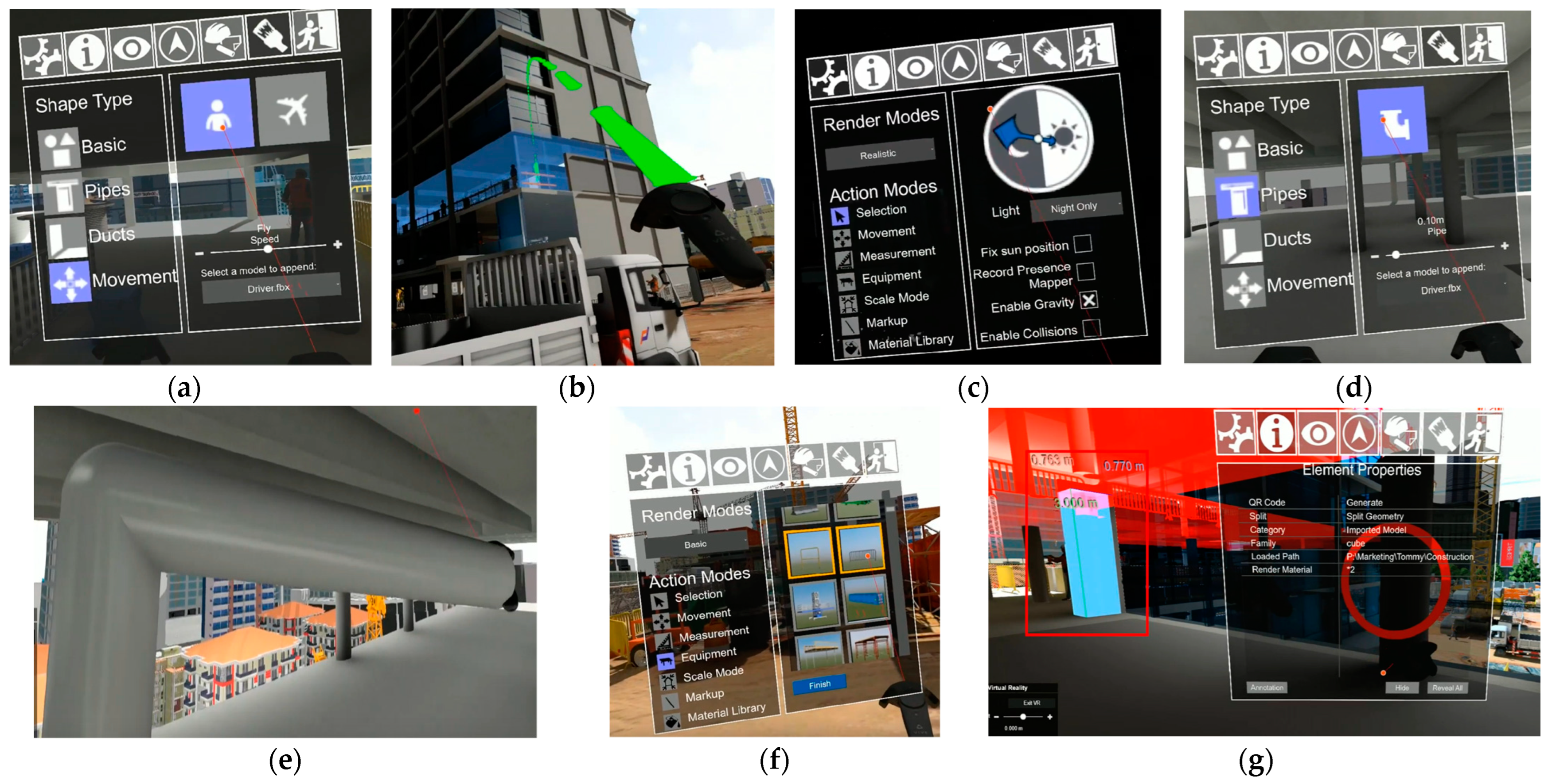
| 1 | Movement | Movement is allowed in two modes, namely Fly and Walk (Enscape, Fader, and IrisVR). Both modes are performed with teleporting as the most recommended way to avoid nausea [11]. | VR software should support Fly and Walk mode in order to allow users to avoid VR sickness. | |
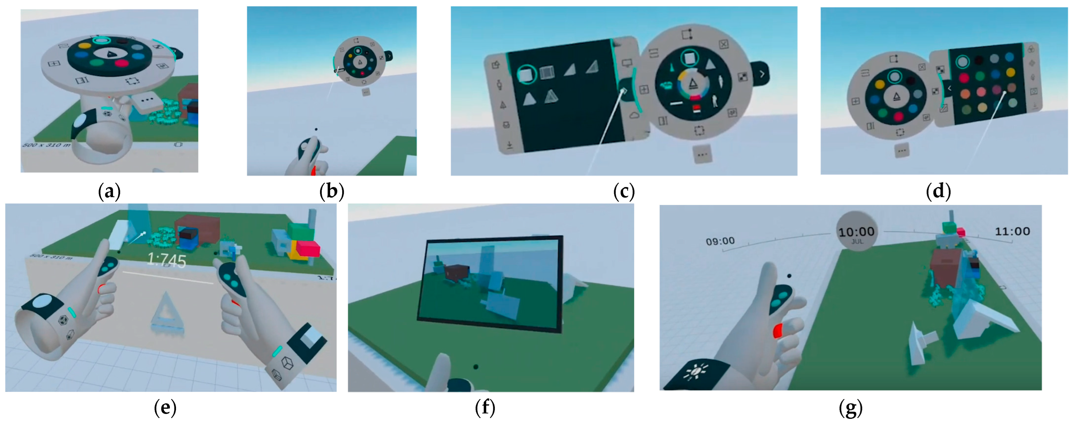
| 2 | Zooming into model | Zooming functionality is achieved by holding both grab buttons in each VR controller and by approaching hands (Arkio, Mindesk, and IrisVR). This also allows the player to change the size of his or her avatar in order to fit into the model. | 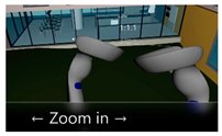 | Holding the two grab buttons and approaching hands should make the user move closer to the table and make the user proportionally smaller. |
| 3 | Rotate Model | In Arkio and Mindesk the selected 3D model is rotated by holding the two grab buttons and steering hands either clock- or counter-clockwise. | Holding both grab buttons and rotating hands should rotate the selected model. | |
| 4 | Toolbar | The toolbar is by default attached to the left VR controller in all VR solutions. The right controller serves as a selection and drawing tool. This is becasue most people are most skilled in selecting things with their right hand. Twinmotion has the option to change this setup for left-handed people. | 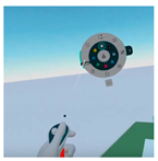 | The toolbar should be on the left VR controller and selections should be made with the right VR Controller (opposite for left-handedness). |
| 5 | Toolbar tweak 1 | The toolbar is an essential tool that is often used. It is handy to attach the toolbar to a static position so that it can be easily accessed rather than opening it again (Arkio). | 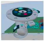 | There should be an option to attach the toolbar to a static position for speeding up workflow. |
| 6 | Toolbar tweak 2 | After a tool is selected and the toolbar closes, it is difficult for the user to remember which tool is active. Arkio has an armband for indicating the active tool. Gravity Sketch indicates which tool is active over the right controller buttons. | Virtual armbands and controllers’ buttons overlays should indicate which tool is active. | |
| 7 | Toolbar organization | The organization of the toolbar in a rounded way (Arkio), or in a sequential way (IrisVR, Twinmotion, and Enscape) is easier to use than complicated vertical and horizontal logic (Gravity Sketch, Holodeck, and Fuzor). | Organize the tools in a rounded or a single logicsequential order. Avoid big grids and subpanels shown together. | |
| 8 | Sliders widgets | In VR it is difficult to move a slider in the toolbar menu. Twinmotion implemented sliders as buttons that slide vertically to change time and weather. |  | For implementing sliders use big buttons that slide upwards or downwards. |
| 9 | Material change | Materials should be overlayed over big buttons and sequential menus (Twinmotion). The material is not easy to perceive while in 2D overview (Hololens and IrisVR). It is better to overview the material wrapped on a sphere (to see reflection properties). | Implement sequential selection menus with material representations in spheres. Do not use file browsers for selecting materials. | |
 | ||||
| 10 | NURBS and polysurfaces | Drawing curves is essential. Gravity Sketch supports it natively; Mindesk supports it through Rhino. |  | Drawing curved lines should be supported natively, i.e., without the use of third party software. |
| 11 | Taking Screenshots | Screenshotting is efficiently performed when a preview screen is available and attached as a screen to the right hand (Arkio and IrisVR). The right trigger should enable photo shooting. | 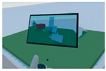 | Have a preview screen on the right hand for taking screenshots. |
| 12 | Transparency in the menu | Transparent menus can cause cognitive stress (Gravity Sketch and Mindesk). Transparency should change automatically based on the contrast between the toolbar and the background. | Auto-contrast for the toolbar transparency reduces cognitive stress. | |
| 13 | Store teleport positions | Teleporting to certain positions is a useful feature. These positions should be able to be saved from the VR menu (IrisVR), not only from the desktop menu (Twinmotion). | 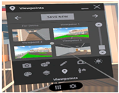 | Enable the ability to save certain positions for fast teleporting. |
Publisher’s Note: MDPI stays neutral with regard to jurisdictional claims in published maps and institutional affiliations. |
© 2022 by the authors. Licensee MDPI, Basel, Switzerland. This article is an open access article distributed under the terms and conditions of the Creative Commons Attribution (CC BY) license (https://creativecommons.org/licenses/by/4.0/).
Share and Cite
Ververidis, D.; Nikolopoulos, S.; Kompatsiaris, I. A Review of Collaborative Virtual Reality Systems for the Architecture, Engineering, and Construction Industry. Architecture 2022, 2, 476-496. https://doi.org/10.3390/architecture2030027
Ververidis D, Nikolopoulos S, Kompatsiaris I. A Review of Collaborative Virtual Reality Systems for the Architecture, Engineering, and Construction Industry. Architecture. 2022; 2(3):476-496. https://doi.org/10.3390/architecture2030027
Chicago/Turabian StyleVerveridis, Dimitrios, Spiros Nikolopoulos, and Ioannis Kompatsiaris. 2022. "A Review of Collaborative Virtual Reality Systems for the Architecture, Engineering, and Construction Industry" Architecture 2, no. 3: 476-496. https://doi.org/10.3390/architecture2030027
APA StyleVerveridis, D., Nikolopoulos, S., & Kompatsiaris, I. (2022). A Review of Collaborative Virtual Reality Systems for the Architecture, Engineering, and Construction Industry. Architecture, 2(3), 476-496. https://doi.org/10.3390/architecture2030027