Article

Bounce: A High Performance Satellite-Based Blockchain System

by
Xiaoteng Liu
,
Taegyun Kim
and
Dennis E. Shasha
*
Department of Computer Science, Courant Institute of Mathematical Sciences, New York University, New York, NY 10012, USA
*
Author to whom correspondence should be addressed.
Submission received: 10 February 2025 / Revised: 15 March 2025 / Accepted: 24 March 2025 / Published: 31 March 2025

Abstract

:
Blockchains are designed to produce a secure, append-only sequence of transactions. Establishing transaction sequentiality is typically achieved by underlying consensus protocols that either prevent forks entirely (no-forking-ever) or make forks short-lived. The main challenges facing blockchains are to achieve this no-forking condition while achieving high throughput, low response time, and low energy costs. This paper presents the Bounce blockchain protocol along with throughput and response time experiments. The core of the Bounce system is a set of satellites that partition time slots. The satellite for slot i signs a commit record that includes the hash of the commit record of slot i 1 as well as a sequence of zero or more Merkle tree roots whose corresponding Merkle trees each has thousands or millions of transactions. The ledger consists of the transactions in the sequence of the Merkle trees corresponding to the roots of the sequence of commit records. Thus, the satellites work as arbiters that decide the next block(s) for the blockchain. Satellites orbiting around the Earth are harder to tamper with and harder to isolate than terrestrial data centers, though our protocol could work with terrestrial data centers as well. Under reasonable assumptions—intermittently failing but non-Byzantine (i.e., non-traitorous) satellites, possibly Byzantine Ground Stations, and “exposure-averse” administrators—the Bounce System achieves high availability and a no-fork-ever blockchain. Our experiments show that the protocol achieves high transactional throughput (5.2 million transactions per two-second slot), low response time (less than three seconds for “premium” transactions and less than ten seconds for “economy” transactions), and minimal energy consumption (under 0.05 joules per transaction). Moreover, given five more cloud sites of the kinds currently available in CloudLab, Clemson, we show how the design could achieve throughputs of 15.2 million transactions per two second slot with the same response time profile.

1. Introduction

The base layer of a blockchain is meant to provide a single, immutable history containing a total ordering over all committed transactions. This immutable total ordering is called the blockchain ledger or, simply, ledger.
Here the word single (also known as unforked) means the following: if agent A sees a block of transactions x 1 before x 2 in the blockchain, then any principal B will see x 1 before x 2 . (Some blockchains, such as Bitcoin [1], provide a slightly weaker common prefix property [2]. They guarantee only that all parties agree to a growing prefix of the blockchain with high probability.) The term immutable means that once x 1 and x 2 are in the chain, they will both remain in the chain and their order will remain as x 1 before x 2 . Immutability is achieved in practice by widespread replication of the blockchain.
Malicious actors have an interest in introducing forks in blockchains [1]. A double-spending attack, which refers to the ability to spend the same funds more than once, can be performed by introducing forks into a blockchain and spending the same funds in each fork but for different goods or services.
In addition to preventing forking (or at least long-lived forks), all protocols inherently rely on a set of administrators who are responsible for monitoring the protocol and updating software to enhance its proper functioning. The reliance on these administrators is generally accepted because their intervention is ’punctuated’: infrequent, and, in theory, transparent to the public. The practicality of this transparency assumption is questionable, especially when complex software is updated.
Achieving high throughput, low latency, and resilience against forks remains a challenging trifecta. Current consensus mechanisms often trade off one dimension of performance for another, leaving gaps in scalability and trustworthiness.
Satellites as system components offer some potential benefits such as global coverage, resistance to tampering, and natural broadcast capabilities. By utilizing satellites as consensus nodes, the Bounce protocol achieves a throughput tens to hundreds of times faster than existing systems and response times in three to ten seconds, all while guaranteeing a no-fork-ever blockchain.
In order to make this paper self-contained, through Section 4, we heavily paraphrase parts of the second two authors’ book [3], recapitulating the assumptions and the overall design presented in that book. This paper extends that book to make the following contributions:
  • This paper allows commit records to consist of multiple Merkle roots instead of just one, thus increasing throughput and reducing response time.
  • This paper introduces the notion of two tiers of transactions: economy and premium. The system can achieve a higher throughput with economy transactions than premium ones, but premium transactions enjoy a shorter response time.
  • This paper presents end-to-end experiments with all components and with earth-to-satellite-to-earth times taken from previous experiments with the International Space Station, adjusted for the higher altitude of low-earth orbiting satellites. We do not specify the exact kind of satellite but do specify and test the hardware of the Bounce Unit to be embedded on each satellite. Our experiments show a sustained throughput of 5.2 million transactions per two-second slot and 3 to 10 s response times.
  • This paper describes the design and implementation of “accumulator” nodes whose job is to maintain account balances based on payment transactions. Section 6 shows that with current hardware, each such node can keep track of balances of up to 1 billion client accounts at 4 million transaction per second throughput rates, thus preventing double-spending.

2. Related Work

This section describes the landscape of blockchain protocols, the use of satellites, and the highest performance blockchain systems.

2.1. Blockchain Protocol Landscape

There are two categories of blockchain protocols:
  • In permissionless (or decentralized) protocols, any principal may add blocks to the blockchain; by contrast,
  • in permissioned protocols, only certain pre-selected principals may do so.

2.1.1. Permissionless Protocols

Among the many permissionless approaches, proof of work and proof of stake are the most popular. Proof of work requires the would-be appenders to the blockchain to solve a computationally difficult problem. The first agent that does so has the right to append a block on the blockchain. The original Bitcoin protocol [1] introduced this core idea and many successors follow it. This approach can, unfortunately, fail whenever malicious principals control a majority of the computing power  [1,2]. Proof of work also incurs high energy costs with its associated environmental burden. According to one estimate [4], Bitcoin’s annual electricity is about the level of entire nations, e.g., Pakistan or Ukraine. Observers [5,6] have noted the curious fact that the energy consumed by Bitcoin has historically been roughly proportional to the value stored among its clients.
Proof of stake is based on a protocol in which principals use a voting mechanism to reach consensus on new blocks. Each principal’s votes are proportional to that principal’s monetary stake in the system. Ethereum switched to Proof of stake in September 2022, vastly reducing its energy footprint. This approach can fail, however, if the majority of shareholders in the system conspire to act maliciously [7,8]. Some researchers [9,10] have pointed out that malicious agents may control less than 1/3 of the stake and yet may still be able to induce forks in the blockchain. Here are some of the subtle attacks on proof of stake protocols: (i) nothing-at-stake attacks [11], (ii) retroactive (“long-range”) stake compromise [12], (iii) stake-bleeding [13], (iv) race-to-the-door takeovers  [5], and (v) selfish endorsing [14]. Furthermore, incentives depend intricately on the reward schedule [15], returns to lending [16], and token valuation [17].

2.1.2. Permissioned Protocols

Centralized approaches embody the opposite philosophy from permissionless consensus. Such an approach entails a single trusted central entity such as a bank [18]. Because this is both simple and efficient, the centralized approach was implicit in the digital cash proposals of the 1980s and 1990s. Unfortunately, the centralized approach entails strong assumptions about the trustworthiness and fault tolerance of the bank. Furthermore, such a bank would wield tremendous power, including the power to censor certain transaction types (or specific transactions) from the network. Such censorship is undesirable in, for example, cryptocurrency applications.
Semi-centralized approaches fall in between. Instead of depending on a single arbiter of consensus as in the banking setting, they manage consensus by requiring a supermajority of semi-trusted principals. The Hyperledger Framework [19] and the Facebook Diem project (formerly Libra) [20] are the most prominent of such systems. Hyperledger’s consensus mechanisms include: (i) Kafka [21], which entails having a single leader order transactions, is vulnerable to fail-traitorous-arbitrary (also known as Byzantine) failures, but is tolerant of fail-crash (also known as fail-stop) failures; (ii) Redundant Byzantine Fault Tolerance [22] allows traitorous nodes as long as they constitute fewer than 1/3 of the total nodes participating in the protocol; (iii) and trusted computing environment based systems (e.g., based on Intel’s SGX) [23]. By contrast, Diem proposes the use of roughly a dozen semi-trusted nodes which run an original Byzantine fault-tolerant consensus protocol. In summary, any proposal based on semi-trusted entities must either select them very carefully or permit them to be monitored.

2.2. Miniature Satellites and Their Uses

With launch costs as low as $300 k [24], and the increased availability of commercial off the shelf (COTS) components, miniature satellites are becoming more common. For example, miniature satellites (a few centimeters on a side), called CubeSats, have become widespread [25,26,27]. One can build one’s own ground station using commercial parts and make use of Ground Stations as a Service [28,29,30]. Even big banks have become involved. J.P. Morgan Onyx [31] deployed Consensys Quorum [32], an Ethereum-based blockchain, to a Low Earth Orbit satellite, and then executed a smart contract on it.
The Bounce protocol is partly inspired by the work of SpaceTee [33] which puts a hardware security module (HSM) in a CubeSat. The authors of the paper founded a company called CryptoSat, and they launched their own satellite [34], and have been providing cryptographic services such as supplying randomness to Ethereum KZG [35,36].
Authors of [37] use satellites as an extra data transmission channel to speed up the transmission of blocks. Authors of [38] designed a satellite-aided consensus mechanism for permissionless blockchains, which used random oracles sent from satellites to select the next block proposer. If the selected block proposer fails to generate a block (e.g., due to missed oracles or satellite link outages), the protocol allows the blockchain to continue evolving. This might lead to temporary forks or orphaned blocks, and the system resolves these through Proof of Work-like longest-chain selection rules. However, users can collude to cause a fork.

2.3. High Performance Blockchain Systems

The two most important performance criteria for a blockchain are throughput (the number of transactions that can enter the blockchain per second) and response time (the time from when a client sends a transaction to the blockchain server to the time when the transaction is placed on the blockchain). Response time is important because consumers and businesses do not want to wait, e.g., for the completion of a credit card transaction. Throughput is important because a blockchain is most useful when many agents can use it concurrently, requiring a high rate of transactions per second.
In an effort to increase transaction throughput and reduce block confirmation time, several approaches have been proposed and implemented. One goal is to achieve throughputs and response times at the level of the Visa payment system, which handles up to 65,000 transactions per second (tps) [39] with a confirmation time of less than a few seconds.
When the Ethereum Merge [40] took place, Ethereum’s consensus mechanism changed to Proof of Stake (PoS) from Proof of Work (PoW). With the update, transaction finality is no longer probabilistic but transaction response time could be as long as 6.4 min (32 slots ∗ 12 s/slot). According to Vitalik, Ethereum can support up to 100,000 tps with the Merge. As of January 2025, Ethereum on average handles around 13 transactions per second [41].
Solana [42] combines Proof of Stake with a hash-chaining concept called Proof of History to order transactions. Around every 400 ms, Solana produces a new block but it could still take up to 32 slots to finalize it, up to 13 s. As of October 2024, Solana handles up to 5200 transactions per second in production and will be able to handle up to 65,000 tps according to its benchmarks [43].
Polkadot [44] employs a multi-chain architecture which enables parallel transaction processing to improve throughput [44]. It produces a block every 6 s, and it takes from 12 to 60 s for transactions to be finalized. It currently serves 1000 tps with plans to upgrade capacity to 100k tps.
Avalanche [45] is composed of multiple blockchains, and uses a directed acyclic graph (DAG) structure to enable parallel processing of transactions. Blocks are produced every two seconds on Avalanche, and once one is produced it’s final. Avalanche serves 10 transactions per second.
Algorand [46] provides rapid finalization and high throughput using Byzantine Agreement. Validators are securely selected by verifiable random functions. Algorand produces a block every 2.85 s and can hold up to 25,000 transactions, which results in a throughput of over 10,000 transactions per second [47].
Table 1 compares the throughputs and response times of the principal high performance blockchains including Bounce, whose throughput is roughly 100 times its nearest competitor.
Thus, the main contributions of Bounce compared to the state of the art are far lower energy expenditure than fully distributed protocols such as BitCoin, high throughput (in the millions of transactions per second), fault tolerance, and low response time. We will also show that the design is scalable, because the critical path consists of sending and validating arrays of Merkle roots. This enables throughput to increase further without increasing response time.

3. Bounce Protocol

3.1. Components

The Bounce system Figure 1 consists of (i) several satellites each carrying a Bounce Unit consisting of a Read-Only memory and hardware that performs communication, cryptographic primitives, and basic computation, preferably embedded in a tamper-resistant package having the functionality of a hardware security module [33]; (ii) a set of terrestrial Sending Stations that package user transactions into blocks and send blocks to satellite Bounce Units (iii) a set of Broadcast Ground Stations that communicate with Sending Stations and satellites; (iv) a communications infrastructure allowing the Broadcast Ground Stations to communicate among themselves and with the other terrestrial components and to send information to the worldwide users of the blockchain; and (v) a Mission Control component, which assigns slots to satellites and assigns roles to the terrestrial components.

3.2. Straw-Man Multi-Satellite Protocol

To make the idea clear, we’ll first describe a simplified protocol assuming that the satellites never fail. We divide time into slots, where each slot is the responsibility of exactly one satellite. The protocol for slot i is the following:
  • Each of possibly several Sending Stations gathers transactions and forms a single Merkle tree.
  • Each such Sending Station constructs a message consisting of the signed root of its Merkle tree and signs and sends that root to the satellite for slot i (phase 1). Please note that for the sake of simplicity, we describe this protocol as sending only one root per Sending Station message; we will generalize this in Section 4. Also, for the sake of simplicity, though the protocol speaks of Sending Stations communicating directly with satellites, there could be specially-equipped relay stations which do the actual communication with the satellites. Some Sending Stations could be relay stations themselves, but need not be.
  • The satellite for slot i constructs a Commit Record that contains (a) the number i and (b) an array of one or more of those Sending Station messages.
  • The satellite signs and sends that Commit Record back to earth (phase 2).
Thus, the satellite for each slot constructs a signed Commit Record containing a sequence of zero or more Merkle roots for that slot. The contents of the blockchain are the contents of the Merkle trees whose roots are signed in slot order by the satellites, and, within each slot, in the satellite-imposed sequence order within the slot.
Even if we assume the satellites are reliable, the Sending Stations and Ground Control may fail. Here we present a few such issues and preview what the protocol in Section 4 does to handle it.
  • Malicious Sending Stations may perform a denial of service attack by sending roots to non-existent Merkle trees to a satellite.
    Response: Because Sending Stations sign their messages, those misbehaving Sending Station would be exposed.
  • A Sending Station might send the root of a legitimate Merkle tree, but then fail before the corresponding Merkle tree has been disseminated.
    Response: In the full protocol, a number of Broadcast Ground Stations Figure 1 will each sign the Merkle root which the Sending Station assembles into a multisignature and sends. Those Broadcast Ground Stations send the Merkle tree to many users with goal of making the tree “widespread knowledge”. As mentioned above, fault tolerance is achieved by replication. Even if some Ground Stations fail later, the widely spread Merkle tree will be in the hands of many nodes.
  • The Commit Record might be sent to earth but then might never be broadcast sufficiently widely.
    Response: Just as for Merkle roots, the Sending Station message for slot i will contain the Commit Record of slot i 1 multisigned by many Broadcast Ground Stations. Before  signing the Commit Record for slot i 1 , each Broadcast Ground Station will make sure that Commit Record is widespread. Thus the satellite for slot i will send its own Commit Record only if it receives at least one Sending Station message with the multisigned Commit Record of slot i 1 . If no such Sending Station message arrives, then that satellite will send a “negative” Commit Record indicating failure. Note that even one working Broadcast Ground Station is enough to make Commit Record information widespread. Broadcast Ground Stations play the role of a relay. They do not execute a consensus protocol.
  • The Merkle tree contains invalid transactions, reflecting double-spending or over-draft spending.
    Response: The block could still be committed. Payment transactions will be handled at Accumulator nodes as described in Section 4.3. Any node that maintains a view of the full ledger can become an accumulator node.
  • By design, Mission Control is supposed to assign just one satellite to each slot. If Mission Control became malicious, it might allow forks.
    Response: By construction, Mission Control will be governed by a small set (say 20 to 100) of reputation-conscious individuals. If a Mission Control person misbehaves, that bad behavior will be reflected in its simple-to-interpret signed assignments of roles. That would discredit that human administrator, see Section 3.3.3.

3.3. Trust Model

Our trust assumptions concern each component of the system: satellites, Ground Stations, and  Mission Control.

3.3.1. Public Key Infrastructure

  • All components ( satellite Bounce Units, Sending Station, and Broadcast Ground Station) have access to a public key infrastructure (PKI), managed by Mission Control. The result is that each Component knows the public key of all other Components.
  • The Mission Control Administrators will determine for each Component A whether A is a Sending Station, Broadcast Ground Station, or  Bounce Unit. Some terrestrial components may take on several roles.
  • For fault tolerance reasons, there will be several satellites. Mission Control will determine which satellite is responsible for which time slot. During each time slot, the responsible satellite will create a Commit Record containing an array of roots of zero or more Merkle Trees that will be added to the blockchain. All Components know these slot assignments.

3.3.2. Satellite Assumptions

Non-traitorous satellite assumption: Each satellite contains a single processor called a Bounce Unit that implements the Bounce protocol. As we will see, protocol is quite simple, so it can be verified and burned in as read-only memory. For this reason, we assume that the only failures a Bounce Unit can suffer are to stop processing, either permanently or intermittently. That is, we assume no traitorous (e.g., Byzantine) failures.
This assumption is reinforced by the fact that it is impractical to capture a satellite to modify it and the Bounce Unit can be made tamper resistant (i.e., self-destruct in case of tampering). A would-be adversary can force omission failures by attacking the satellite or its communications, but cannot force traitorous failures.
Approximate synchrony assumption: The satellites agree on the time to within a known bound, say 100 milliseconds of the real time. Satellite clocks fall easily within this bound given an occasional beacon from a time server.

3.3.3. Notification Assumptions

The following assumptions ensure that enough Broadcast Ground Stations behave correctly to take Merkle Tree transactions sent by Sending Stations or Commit Records sent by satellites and make such information widespread. If these assumptions do not hold, users of the blockchain will know because they will not receive Commit Records every few seconds.
f-failure assumption: For some parameter f, no more than f Broadcast Ground Stations will fail. However, a failing Broadcast Ground Station may fail traitorously (by commission in a Byzantine way) or by omission. In the later sections, starting with Section 4, when we refer to multisignatures, we assume that each multisignature will be derived from the signatures of at least f + 1 Broadcast Ground Stations.
Widespread Knowledge assumption: Every working Broadcast Ground Station can send a message to enough sites that the message won’t be lost and will be found if Mission Control polls for it. Information that has been broadcast this way is said to be widespread knowledge. Some sites will be Accumulator sites (see Section 4.3) that maintain wallets and prevent double-spending. The traitorous Ground Stations can’t do any harm from a safety perspective, because  only roots that are signed by some slot’s satellite will be recorded on the blockchain.
Mission Control Assumptions
Mission Control sends messages very occasionally: only when “Resets” occur which happens only when a satellite fails. For that reason, the messages sent by Mission Control can be closely monitored by human users. Those messages assign slots to satellites and authenticate Sending Stations and Broadcast Ground Stations therefore are easy to parse. The protocol for resets is straightforward but lengthy so please see our book [3].
The assumption of exposure aversion is that each administrator of Mission Control will avoid signing any message that embodies bad behavior. Bad behavior includes assigning the same slot to multiple satellites, validating bad Sending Stations, or validating bad Broadcast Ground Stations, all of which would be obvious by simple inspection of any “Reset message” which makes all these assignments.

3.4. The Case for Satellites

Now that we understand the protocol and its timing, let us take a step back to revisit the possible benefits of satellites over protected terrestrial data centers.
  • Satellites support broadcast. A satellite can send to many places on the Earth at once. At altitude 550 km, and elevation angle 40 degrees, a single Low Earth Orbit (LEO) satellite can cover an area of 1,000,000 km2, bigger than the country of France [48]. This makes satellite communications more jam-resistant than a data center. Jam resistance can be further enhanced by having each satellite send information to other satellites.
  • As anyone who has kept up with the hacking literature knows, proximity leads to compromise. Side channel power attacks for example are known to compromise keys, when the attacker is within a few meters of the device. The remoteness of satellites makes such attacks impossible.
  • Finally, gaining physical possession of a 10 cm cube in space would be both challenging (even for state actors) and extremely obvious. Even if that were possible, tamper-resistance (i.e., self-destruction in case of tampering) is easy to build in.

4. Slot Protocol

In this section, we describe the protocol for each slot i with reference to Figure 2. Then we review failures and responses to failures. Finally, we describe a design to support one higher level use case: payment.

4.1. Core Bounce Blockchain Protocol

Step 1 (Before slot i begins) Each Sending Station that wishes to participate in the slot assembles one or more Merkle trees for slot i: A Sending Station adds each submitted transaction to some list L. If the clock time is at d seconds before the beginning of slot i, the Sending Station for that slot builds a Merkle tree T using the transactions in L. The Merkle tree 
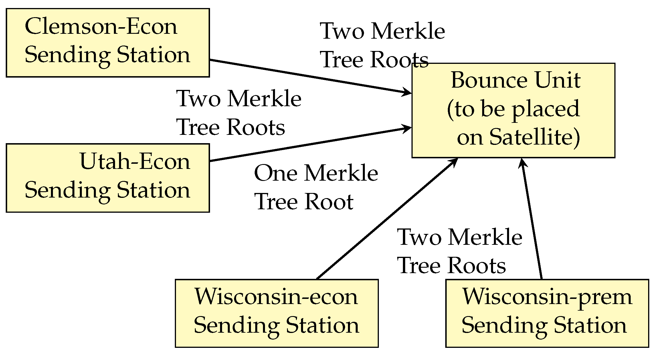
T is then sent to at least f + 1 Broadcast Ground Stations (step 1 in Figure 2 and detailed in Algorithm 1). Each Broadcast Ground Station computes the Merkle root from the Merkle tree and sends the signed root back to the Sending Station as well as to user nodes. User nodes will store that Merkle Tree but will process the contained transactions only after receiving a Commit Record containing the corresponding Merkle Tree root. (step 1’ in Figure 2). The Sending Station then aggregates the f + 1 signatures to a single multisignature as described in Algorithm 2. In our experiments, we set
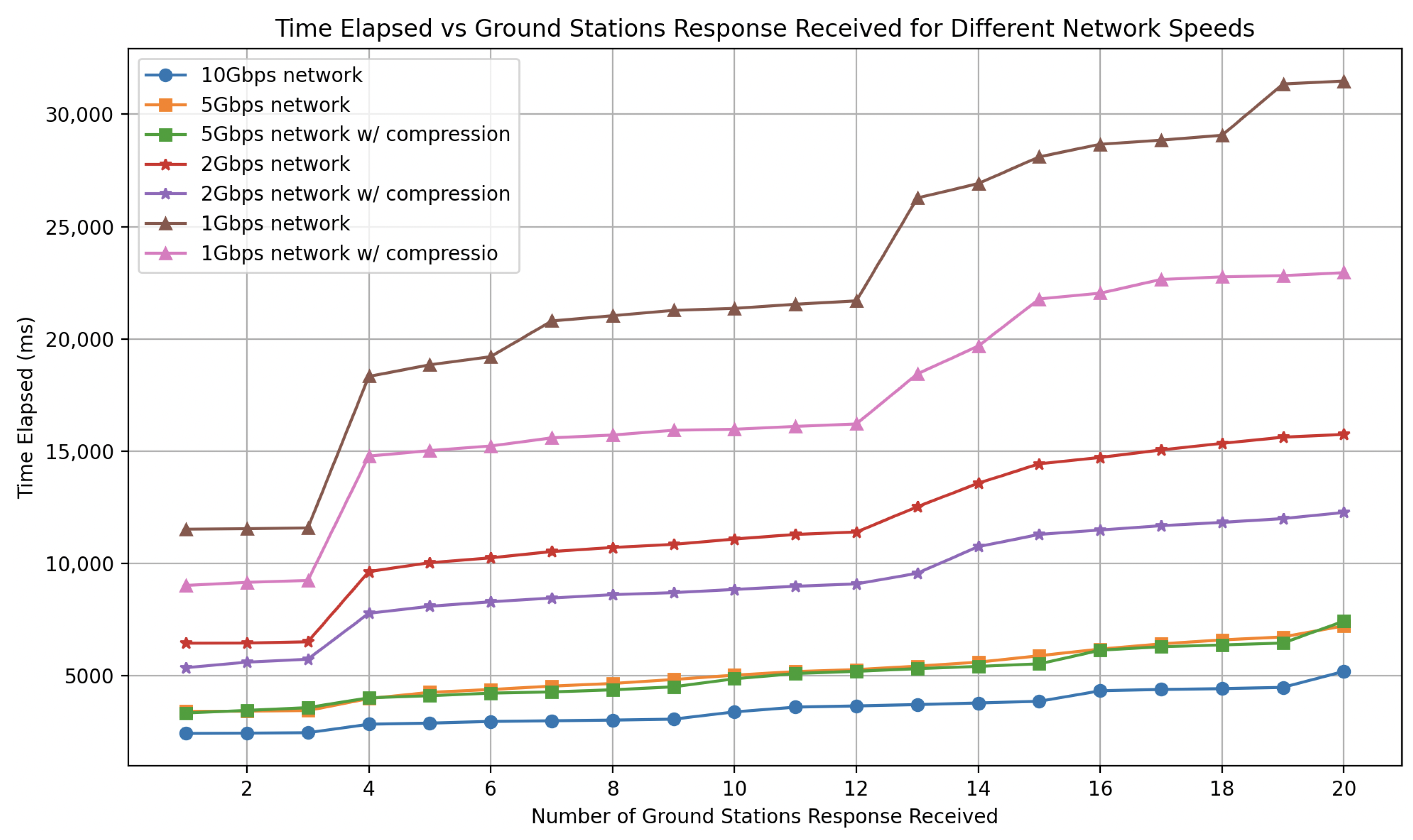
 d to one second and f + 1 to be 80% of the Broadcast Ground Stations as you can see in Section 6.
After the end of slot i 1 , Broadcast Ground Stations multisign the Commit Record for slot i 1 : Separately and possibly concurrently with Merkle Tree construction, f + 1 Broadcast Ground Stations form a multisignature of the Commit Record of slot i 1 . That happens as follows: when a Satellite sends the Commit Record for slot i 1 to a set of Broadcast Ground Stations (step 2 in Figure 2), each receiving Broadcast Ground Station G broadcasts the Commit Record to at least f other Broadcast Ground Stations. Each receiving Broadcast Ground Station signs the Commit Record and sends it back to G. The Broadcast Ground Station G then aggregates at least f other signatures and its own signature for the Commit Record for slot i 1 into a single multisignature. Then, the Broadcast Ground Station G sends the multisignature to all possible Sending Stations for slot i (step 2’ in Figure 2) as well as to User nodes. Several Broadcast Ground Stations may duplicate this effort for fault tolerance reasons.
Sending Station sends Sending Station message (step 3 in Figure 2): At the beginning of slot i, each Sending Station that wants to participate in slot 
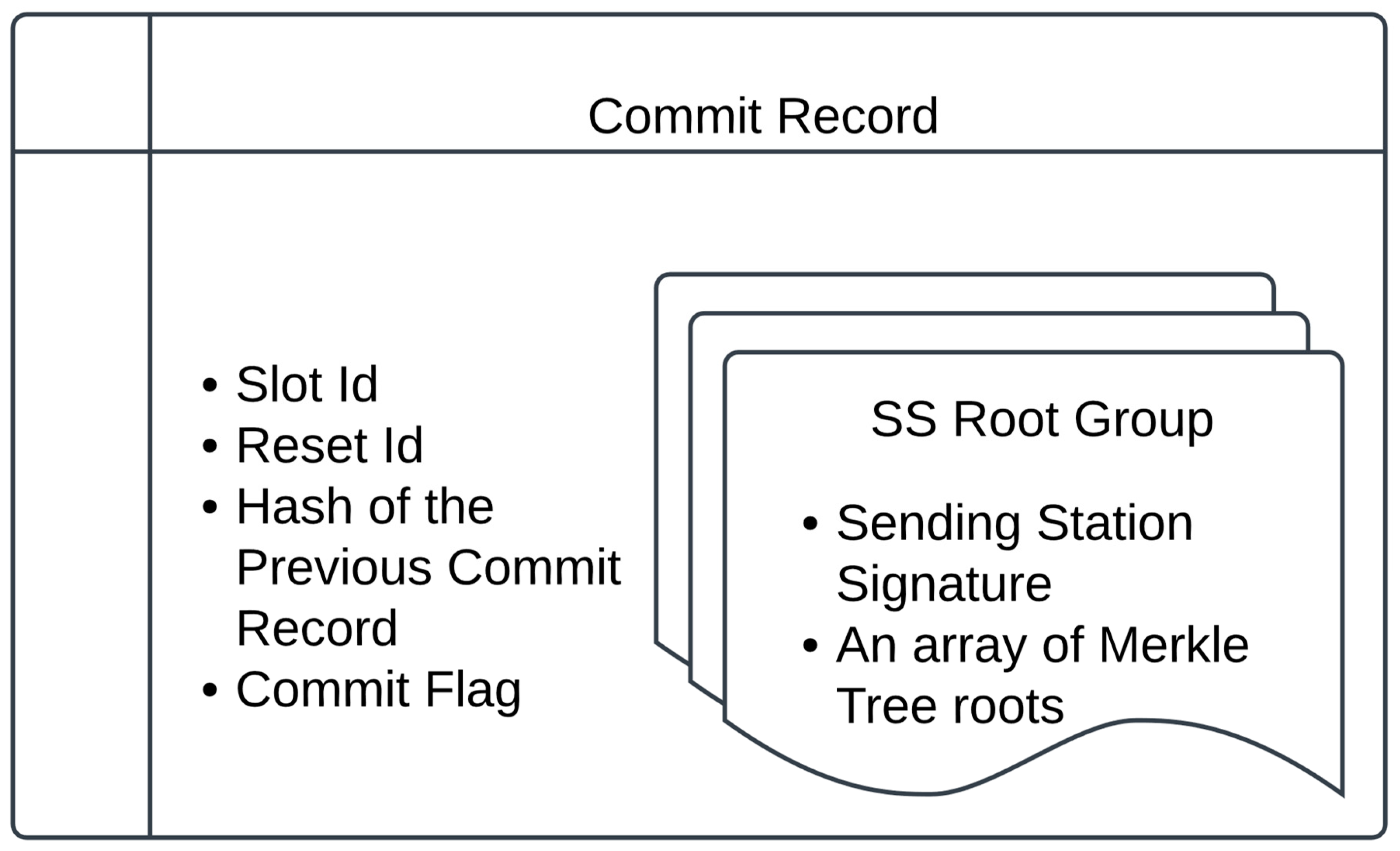
i creates a Sending Station message including both a multisigned Commit Record for slot i 1 and the multisigned Merkle tree root (as described in Algorithm 3). It sends the Sending Station message to the Satellite that is responsible for slot i. There could be multiple Sending Stations creating and sending the Sending Station messages to the same satellite for each slot i.
Satellite creates Commit Record and broadcasts (step 4 in Figure 2): When a Satellite for slot i receives a Sending Station message for that slot, it (a) tests that the signature is indeed signed by the Sending Station, (b) checks the identifier in the Sending Station message is i, (c) validates the multisignature on the Commit Record for slot i 1 , (d) the Commit Record is for slot i 1 and Commit flag set to True, (e) validates the multisignature on the Merkle root (by checking the public keys of the Broadcast Ground Stations).
If all the tests succeed, the Satellite keeps the Sending Station message in a buffer holding the set of valid Sending Station messages. At the beginning of the slot i, the Satellite selects all of the valid Sending Station messages and creates a positive Commit Record with the Merkle Tree root in those Sending Station messages. Even if none of the sending station messages contains a Merkle Tree root, the satellite can still create a positive Commit Record if any valid Sending Station message contains the previous Commit Record.
If the satellite does not receive a previous Commit Record, however, it creates a negative Commit Record saying effectively that the Commit Record for slot i 1 is unavailable. The satellite sends that negative Commit Record to Broadcast Ground Stations which will relay it to Mission Control to do a reset [3]. In the case of a positive Commit Record, the satellite will give a total order of the Merkle Tree roots. If the same Merkle Tree root is contained in multiple Sending Station messages, the satellite keeps only the first.
Algorithm 1 The Sending Stations constructs the Merkle Tree and sends the transactions to Broadcast Ground Stations
1:
Create a SignMerkleTreeRequest object with:
  • txs: List of transactions.
  • sender_ip: The Sending Station’s IP address.
2:
Send the sign_merkle_tree_request to Broadcast Ground Stations in parallel.
3:
Construct a Merkle Tree mt from txs.
4:
Set self.root to the root of mt.
Algorithm 2 Given the Signature of the Merkle Tree Root from a Broadcast Ground Station, the Sending Station checks its validity and if there are enough (viz. f + 1 ) valid root signatures, the Sending Station assembles the multisignature on the Merkle Tree root, using the BLS algorithm of [49,50]
1:
Verify the signature for the given root.
2:
if signature verification fails or root doesn’t match the one created by the Sending Station then
3:
    exit
4:
end if
5:
if the root from this Broadcast Ground Station has already been processed then
6:
    exit
7:
end if
8:
Add the signature to root_to_sigs map.
9:
Retrieve the list of signatures for the root.
10:
if number of signatures f + 1  then
11:
    Initialize a bit vector signers_bitvec.
12:
    for each ground station public key pk do
13:
        for each signature in sigs do
14:
           if signature is valid for pk and root then
15:
               Set corresponding bit in signers_bitvec.
16:
               break inner loop.
17:
           end if
18:
        end for
19:
    end for
20:
    if at least f + 1 distinct signers then
21:
        Create multi_signed based on the signatures.
22:
        Cache multi_signed.
23:
        Mark root as processed and remove from root_to_sigs.
24:
    else
25:
        exit (f+1 check failed).
26:
    end if
27:
end if
(4) Satellite then broadcasts the Commit Record back to Broadcast Ground Stations. This in turn triggers Broadcast Ground Stations to create a multisignature for the Commit Record of slot i.
Broadcast Ground Station broadcasts Satellite Commit Record: The Broadcast Ground Stations make this message (positive or negative Commit Record) widespread by sending it (step 5 in Figure 2) (e.g., on a peer-to-peer network). They also send the Commit Record to the Sending Station (or, in general, Sending Stations) for the next slot, which handles it as described in Algorithm 4.
Users check validity of block: Any user of block i can check the block’s validity by confirming that the Commit Record for slot i: (a) is signed by the satellite for slot i, (b) the Commit Record is positive, (c) the signed Sending Station message has slot i and the Merkle root for slot i in the Commit Record corresponds to the Merkle tree of slot i. Assuming the Commit Record is positive, it now remains for users to check transactions for double-spending and other such abuses. We discuss this in Section 4.3.
Algorithm 3 The Sending Station constructs the Sending Station Message and sends it to the satellite
1:
if no multisigned previous commit record is received then
2:
    exit
3:
end if
4:
Constructs the sending_station_message with:
  • reset_id
  • slot_id
  • txroots: the cached multisigned Merkle Tree roots.
  • prev_cr: the multisigned previous Commit Record.
5:
Sends sending_station_message to the satellite.
Algorithm 4 The Sending Station Handles a multisigned Commit Record
1:
if CommitRecord signature verification fails then
2:
    exit.
3:
end if
4:
if Received cr.reset_id does not match expected self.reset_id then
5:
    exit.
6:
end if
7:
if Received cr.slot_id does not match expected self.slot_id then
8:
    exit.
9:
end if
10:
if Previous CommitRecord exists AND Previous CommitRecord hash does not match the received one then
11:
    exit.
12:
end if
13:
Set self.prev_cr to multi_signed_cr.
Negative Commit Record and Resets
If the user sees that some slot has no Commit Record or the Commit Record is negative, that user should alert Mission Control and show proof of the negative Commit Record. Mission Control then performs a reset [3], which will reassign roles to terrestrial components and create a new slot assignment for satellites.
Briefly, a reset entails identifying the Commit Record of the last committed slot by polling Broadcast Ground Stations and users and re-starting the blockchain at the next slot value, possibly with new slot assignments for satellites and new Broadcast Ground Stations and Sending Stations. For technical reasons, to prevent certain race conditions, there is also a reset number, so the slot identifier is a pair of reset number and slot number. The book [3] shows that the reset protocol is safe given the exposure-aversion trust assumptions.
Moreover, the reset message is simple to interpret because all it’s doing is assigning roles to satellites, Sending stations, and Broadcast Ground Station, so will be simple to monitor. We note that similar reputational mechanisms are used in many applications, including in vehicle-to-vehicle applications [51]. Moreover, users of popular blockchains like Ethereum, must trust the administrators of the system, when they perform software updates.

4.2. Failure/Response Summary

We summarize the possible failure cases, their consequences, and how we handle those in Figure 3. Sending Stations might fail both cleanly (e.g., fail-stop) and traitorously. Neither failure type requires any specific action, because a failing Sending Station cannot forge user transactions nor the signatures of other agent. Sending Station failures do increase the response time of transactions that were sent to the failing Sending Stations. Such transactions will have to be sent to other Sending Stations.
Regarding the assumption of at most f failing (clean and traitorous) Broadcast Ground Stations, with f a number in the high teens, we believe this is reasonable given that the failure of any Broadcast Ground Station will be evident given that it signs a Merkle Tree (or Commit Record), but fails to send that to User Nodes. The only damage f or fewer traitorous Broadcast Ground Stations can do is to cause denial of service. Malicious Ground Stations cannot forge user messages because messages are signed. Moreover, even if only 1 out of f + 1 properly makes information (Merkle trees and Commit Records) widespread, that is sufficient. This is in contrast to consensus algorithms such as Byzantine Fault Tolerance [52] for which a supermajority of agents need to work correctly. Spreading information is simpler than consensus. Denial of service causes a slower response time for some transactions, but does not slow down the whole system.
Recall the assumption that the Bounce Units in the satellites don’t suffer from traitorous failures. We believe that this is reasonable because the Bounce Unit protocol is quite simple (check the signatures of one or more Sending Station messages, sign and send) and therefore can be verified and burned into Read-Only memory. Such an architecture makes Bounce Units secure against remote software modification.
Note however that satellites can fail cleanly, so may fail to send messages either intermittently or permanently. We believe satellite failures will be very infrequent though, on the order of once every few months or years. When such failures do occur, we invoke the reset protocol in which the human participants of Mission Control (over several minutes possibly) decide on a new slot assignment and send a reset message.

4.3. Accumulator Node Algorithms: Account Balances

As mentioned above, to support payments, one or more user nodes, called Accumulators, can maintain the account balances of all account holder based on the ordered sequence of blocks in the blockchain. This is an application concern, so is not our primary focus. Nevertheless, because payments are a core use case of many blockchain systems, we describe the algorithms here and the implementation in Section 7.
There are two main issues, the first having to do with the Bounce protocol itself and the second is generic to payment systems.
  • Because user transactions may be sent to several Sending Stations, the same transaction may appear in several Merkle trees. We would want to avoid processing the same transaction more than once.
  • In a payment setting, we want to guarantee that accounts can’t fall below zero coins.
The overall pseudo-code of an accumulator node is shown in Algorithm 5.
Algorithm 5 The Accumulators Processing Commit Records
1:
Input: Commit record containing root r and corresponding Merkle Tree M ( r ) .
2:
Procedure:
3:
    if r has already been seen (possibly from a different Sending Station) then
4:
      Ignore M ( r )
5:
    else
6:
      for each transaction T in M ( r )  do
7:
         if T has already appeared in the current or a previously committed Merkle tree then
8:
           Ignore T
9:
         else
10:
           Process T
Algorithm 5 ensures that an accumulator does not process the same transaction twice. The “Process T” step requires a data structure. We propose constructing transaction identifiers as the concatenation of the wallet identifier of the payor and a sequence number. The account record for a wallet W consists of W’s wallet id, a balance, and some representation of the sequence numbers of all committed transactions in which W is the payer. In the case where each wallet issues a payment transaction only when all of its previous transactions have already appeared in committed Merkle trees, this representation consists simply of the highest sequence number of any committed transaction.
We now elaborate on what process(T) does in Algorithm 6.
Algorithm 6 The Accumulators Processing a Transaction T for the payer wallet Walletid
1:
Extract transaction identifier of the payer ( Walletid , seqnum ) from T
2:
ifseqnum is not already in the set of committed transactions of Walletid then
3:
    Add seqnum to the set of committed transactions of Walletid
4:
    Execute T which will cause payment if there are sufficient funds in this wallet
5:
end if
If the funds are insufficient, then the execution of T may be modified, either to do nothing or to perform a partial payment. In our algorithms, we assume for simplicity that insufficient funds result in no payment. When there are sufficient funds, an Accumulator node will update both Wallets.

5. Implementation

While this paper has so far mostly summarized the protocols of our book [3], we now describe a concrete implementation and our experiments on that implementation. The prototype is implemented in the Rust programming language. For communication with remote components, we utilize gRPC, except in the case of the Sign Merkle Tree Request, where we open a direct TCP stream. To optimize transaction throughput, each Sending Station entity operates several parallel components. The Sending Station comprises three primary long-running threads: the tx-receiver thread, which handles incoming transactions from clients; the mktree-handler, which performs tasks as described in Section 5.1, Algorithms 1 and 2; and the main sending-station thread, which manages communication with the satellite, Algorithm 3 and 4, and processes messages from Mission Control.
Note: In our implementation, all the algorithms listed here run concurrently. The Sending Station acts like a state machine. After receiving a message, it executes one of these algorithms. A typical message is a multisigned Commit Record or a timer tick. Rust’s Tokio library is used for parallelism and asynchronous execution, and the Rayon library is used for parallelizing CPU-intensive operations.

5.1. Merkle Tree Construction and Multisigning

As explained in Section 4, the construction of the Merkle Tree(s) begins well before the beginning of a given slot i. The Sending Station sends the transaction set L to at least f + 1 Broadcast Ground Stations. (Recall that f is our assumption of the maximum number of Broadcast Ground Stations that will fail, either traitorously or by omission.) In our implementation, the Sending Station uses a small number (the fanout) of the destination Broadcast Ground Stations as relays which in turn uses small numbers of other destination Broadcast Ground Stations as relays until the desired number ( f + 1 ) of destination Broadcast Ground Stations have received the transactions. In our implementation, the fanout is 3.
Because our goal is to process several million transactions per slot, the volume of data transferred could reach several hundred megabytes. Because gRPC’s default message size limit of 4 MB is inadequate at this scale, we use a direct TCP socket connection to communicate millions of transactions. Each Broadcast Ground Station maintains a long-running TCP listener, while the Sending Station establishes a TCP stream to transmit transactions. To minimize serialization and deserialization overhead, we leverage rkyv, a zero-copy deserialization framework for Rust. When network speed is constrained, we use zstd compression.
Upon receiving a request, a Broadcast Ground Station constructs the Merkle Tree, caches it, signs the root, and returns the signed root to the Sending Station. In parallel, the Broadcast Ground Station forwards the request and the transactions to other Broadcast Ground Stations, based on the overlay topology. We use Keccak-256 for hashing when building the Merkle Tree.
The Sending Stations transmit only the transactions in the request and simultaneously construct the Merkle Tree while awaiting responses from Broadcast Ground Stations. When a response is received, the Sending Station verifies the signature, confirms root consistency, and caches it. After accumulating f + 1 valid responses, the Sending Station aggregates the signatures into a multisignature (described in Section 5.3, Algorithm 2) and stores the multisigned root in a queue, ready for transmission to the satellite.

5.2. Storage

The blockchain and transactions are stored in a distributed manner across Broadcast Ground Stations, using RocksDB, a key-value store, to manage this data. The blockchain is structured as follows:
  • The head (most recent block) of the blockchain is represented by the key-value pair “HEAD” c r n , where c r n is the latest commit record.
  • Each commit record is stored as a linked key-value pair, such as c r i c r i 1 , where c r i represents the i-th commit record.
Transactions are stored based on their corresponding root hash, in the format root → transactions. When a Broadcast Ground Station receives a new commit record, c r n + 1 , from the satellite and verifies it as positive, it prepends the block corresponding to c r n + 1 to the blockchain. This entails updating the blockchain head to “HEAD” → c r n + 1 and adds a new key-value link c r n + 1 c r n . The Broadcast Ground Station then stores the cached transactions associated with the root(s) in this commit record as root → transactions.

5.3. Signature Schemes

For the core Bounce protocol, we use the Boneh Lynn Shacham (BLS) signature [49,50,53], as it provides a fast and efficient way to aggregate and verify signatures. BLS signatures can be aggregated into a single signature. Given a set of distinct messages m 1 , , m n , a set of distinct secret keys s k 1 , , s k n , and signatures s 1 , , s n on the messages signed by respective private keys, (i.e., s i = S i g n ( s k i , m i ) , the aggregate signature s = A g g r e g a t e ( s 1 , , s n ) is a valid signature, i.e., V e r i f y ( s , [ m 1 , , m n ] , p k ) = t r u e , where p k = A g g r e g a t e ( p k 1 , p k n ) is the aggregate public key of the secret keys.
To defend against rogue key attacks, BLS IRTF Draft V5 [50] provides three different variants of the scheme: Basic, Message Augmentation, and Proof of Possession. We use the Proof of Possession variant of the scheme. In this variant, the public keys need to be validated before they can be used to verify signatures. Each component in our implementation verifies the public key when the reset message distributes public keys of other components.
As we’re using the Proof of Possession scheme, we make use of fast verification of aggregate signatures on the same message. In our protocol, we have a common pattern where a single component (e.g., Sending Station) sends a request to other components (e.g., Broadcast Ground Stations or Satellite) to sign a Merkle root or Commit Record. The requesting component then aggregates the returned signatures into a single signature, and broadcasts it.
We’re aware that BLS IRTF draft [50] and the Rust library we’re using  [53] are vulnerable to splitting zero attacks [54] if the non-fast variant of aggregate verify in BLS is used. For that reason, we don’t use the non-fast variant but rather the fast variant of aggregate verify to avoid the vulnerability.

5.4. Prototype Public Key Infrastructure

In our implementation, each agent’s (whether Sending Station, Broadcast Ground Station, and satellite Bounce Unit) private key and corresponding public key are initialized using the BLS algorithm. Mission Control has all agents’ public keys. At the very beginning of the protocol, Mission Control, acting as a Certificate authority, sends a start message, which contains the public keys of all the agents to all agents, so that each agent can authenticate messages from other agents.

6. Experiments, Results, and Analysis

All experiments, unless otherwise noted, were conducted on CloudLab, utilizing the c220g2 node type https://docs.cloudlab.us/hardware.html (last accessed 7 March 2025) for Sending Stations and Broadcast Ground Stations and a Raspberry Pi 4 in the (eventually satellite-carried) Bounce Unit. We chose the Raspberry Pi because these are frequently used onboard satellites https://www.raspberrypi.com/news/raspberry-pi-zero-powers-cubesat-space-mission/ (last accessed 7 March 2025). The main parameter values are presented in Table 2.
The energy consumption of c220g2 type servers can be calculated from the processor type. It has two Intel E5-2660 v3 CPUs, each with a 105 W Thermal Design Power, which gives 210 W in total. https://www.intel.com/content/www/us/en/products/sku/81706/intel-xeon-processor-e52660-v3-25m-cache-2-60-ghz/specifications.html (last accessed 7 March 2025).
Therefore, a setting with say 100 such processors is the equivalent of about 210 light bulbs, that is 21 kilowatts. This comes to a yearly consumption of 184 megawatt-hours, about the energy load of 20 homes in the United States. The satellites themselves run on solar energy, so incur no extra energy costs and earth to satellite transmissions require under 100 watts. In terms of energy per transaction, this comes to under 0.05 joules per transaction, while other systems use between 10s and millions of joules per transaction.

6.1. Merkle Tree Construction Benchmark

Table 3 shows the construction times on a single node of a Merkle Tree of different sizes. The results indicate that the construction time scales nearly linearly with the number of transactions (each transaction is 392 bytes, the approximate size of a bitcoin transaction). Thus, on a single compute node, one million transaction Merkle Tree can be constructed in under one second.

6.2. Multiple Broadcast Ground Station Merkle Tree Construction Performance

In this experiment, the Sending Station and Broadcast Ground Stations are deployed within a single cluster (CloudLab, Wisconsin). The overlay network is structured as a tree, called the broadcast tree with a fixed fanout of 3. The experimental setup involves one Sending Station and 39 Broadcast Ground Stations of which 19 must respond with signed roots (i.e., 19 = f + 1 ). Again (and hereafter) each transaction is 392 bytes.
Figure 4 illustrates the time elapsed from the initiation of the send operation by the Sending Station until responses are received from the Broadcast Ground Stations. The network configuration includes a 10 Gbps interconnect between each node, with an overlay network broadcast tree constructed with a fanout of 3, meaning that the Sending Station initially transmits data to three Broadcast Ground Stations, and each non-leaf Broadcast Ground Station subsequently forwards the request to three child Broadcast Ground Stations.
The tests did not use data compression, because previous assessments indicated that, when using a high-speed interconnect, compression and decompression took more time than was saved in communication. For one million transactions, the system takes under 4 s to receive responses from 19 Broadcast Ground Stations. For Merkle Trees containing 100,000 transactions, the Sending Station processes signed responses from all Broadcast Ground Stations in less than one second.
Figure 5 shows the response time with different fanouts of the overlay graph as a tree. A fanout of 3 works well for 39 Broadcast Ground Stations, because then the broadcast tree has exactly four levels with the Sending Station as the root at level one. The fanout is configurable based on the number of Broadcast Ground Stations. System architects can also customize the network graph based on their network interconnection settings.
In the following section, we focus on the 10 Gbps network setup. Appendix A analyzes the impact of different network speeds. We assume that users can establish at least a 10 Gbps interconnect between Broadcast Ground Stations, even across significant geographic distances. This assumption is reasonable because Data Center Interconnect (DCI) providers offer high-speed connections ranging from 100 km (Metro DCI) to thousands of kilometers (Subsea DCI) with bandwidth capabilities well beyond 10 Gbps [55,56,57].

6.3. Slot Protocol Measurements

Table 4 shows the time taken for each step of the slot protocol. The time from the Sending Stations to the Satellite and back to Broadcast Ground Stations are estimations based on the experiments with the International Space Station [3], which is approximately 0.5 millisecond closer to the earth based on the speed of light than a typical low earth orbiting satellite (altitude of 400 km vs. 550 km, with the 150 km taking 0.5 milliseconds at the speed of light) The total time for the slot protocol is around 1 s. Based on this timing, we can evaluate the sustained throughput and response time of our protocol.
Section 6.3.1 presents the most naive design with one Merkle tree per slot. Section 6.3.2 then describes a design in which we collect multiple Merkle trees in a slot to reduce the response time and increase throughput.

6.3.1. Throughput and Response Time of the One Root per Slot Protocol

In our protocol, (i) several Merkle Trees can be constructed in parallel and (ii) Merkle Tree construction is decoupled from the Sending Station-Satellite-Broadcast Ground Station flow within a slot. That is, a Sending Station begins a slot with the multisigned root of a Merkle Tree and the multisigned Commit Record of the previous slot.
Assume we set the slot time to be one second and f = 18 (i.e., 18 Broadcast Ground Stations could be traitorous), so the Merkle tree and transactions will need to be spread to 39 Broadcast Ground Stations and receive a multisignature with at least 19 signatures from different Broadcast Ground Stations for the Merkle Tree. This means the Sending Station sends a Signed Merkle Tree Request with one million transactions to the Broadcast Ground Stations.
Given the timing in Figure 4, constructing the Merkle Tree on at least 19 nodes and forming the multisignature will take under four seconds. Given these numbers, we can support a sustained throughput of one million transactions per second by initiating one Merkle Tree construction every second. Because the multisignatures require 4 s, the response time will be 5 s. Figure 6 illustrates how this pipelining works. For example, the Sending Station sends the Sign Merkle Tree Request for tree T 1 with one million transactions at time 1. At time 5, the Sending Station receives the signatures from 20 Broadcast Ground Stations and creates the multisigned signature for T 1 , and then at time 6 (slot 6), the satellite commits T 1 .

6.3.2. Throughput and Response Time of the Multiple Roots per Slot Protocol

The previous design assumes that all Merkle Trees contain one million transactions, with only a single multisigned Merkle Tree root sent per slot. However, this design can be significantly improved.
  • The first improvement is to allow “premium” transactions using 100,000-transaction Merkle Trees, while “economy” transactions are processed in 1-million-transaction Merkle Trees.
  • The second improvement is to send many multisigned Merkle roots in an array, as illustrated in Figure 7, instead of just one.
  • The third improvement is to allow the satellite to commit multiple Sending Station messages during a single slot.
By integrating these enhancements, we achieve faster response times: two to three seconds for premium transactions and four to nine seconds for economy transactions, as shown in Figure 8. Regarding throughput, Figure 8 shows that starting with the commit at second 6, this deployment can achieve a throughput per slot of 5.2 million transactions per slot. (200,000 of which are premium transactions) and sometimes 6.2 million transactions per slot. In this configuration, one Sending station at Clemson CloudLab contributes two economy roots, as does Utah. Wisconsin CloudLab contributes one economy root from one Sending Station and two premium roots from another.

6.3.3. Scaling to Higher Throughputs

Bounce can handle high transaction loads by ensuring that disjoint sets of transactions are processed in parallel as illustrated above. This could easily be scaled further. For instance, k p premium Merkle Trees and k e economy Merkle Trees can be constructed concurrently. This parallelism not only improves throughput but also reduces response time, because there could be more premium Merkle Trees. For example, given five more Cloud Lab, Clemson clusters, we could add ten more economy Merkle Trees per slot, raising the throughput per slot to 15.2 million transactions per second.
The Sending Station can assign Merkle Trees to different Broadcast Ground Stations or disjoint groups of at least f + 1 Broadcast Ground Stations. An architecture in which different Merkle Trees are built by disjoint sets of processors ensures that an essentially arbitrary number of Merkle Trees can be built in parallel. The only part of a slot whose timing might slow down if there are many Merkle Trees is the satellite processing time.
Specifically, the satellite Bounce Unit would have to verify multiple roots. This could potentially increase the slot time length, because it is in the critical path and is not parallelizable.
Table 5 illustrates the impact of having multiple Merkle Tree roots on slot timing. The time for a Sending Station to create a message remains unchanged even if it must send up to 10 roots. The satellite Bounce Unit’s validation time increases by approximately 6 milliseconds per additional multisigned root, because it must validate signatures from multiple Broadcast Ground Stations (and a Raspberry Pi 4 is far slower than a server computer).
For example, if each Sending Station message contains five roots and there are ten messages from ten different Sending Station messages, the total validation time at the Bounce Unit would still be under 0.5 s. Such a setup would allow the system to maintain a slot duration of two seconds and support ten sets of 100,000 premium transactions and 40 sets of 1,000,000 economy transactions.
Here we have limited ourselves to what the accumulator node of Section 7 can handle, which is 4 million transactions per second. Better implementations or better hardware could raise that number.

6.3.4. Response Time/Throughput Tradeoff

As observed above, Table 3 shows a linear relationship between the number of transactions and the time required to construct a Merkle Tree on a single node. That is, constructing k Merkle Trees of size n / k sequentially takes approximately the same time as building a single large Merkle Tree of size n. By contrast, the communication portion of the Merkle Tree multisignatures scales sub-linearly as shown in Figure 4. So, acquiring multisignatures on k Merkle Trees of size n / k will take longer than acquiring multisignatures on a single large Merkle Tree of size n.
Therefore, breaking up a one million Merkle Tree into 10 Merkle Trees each holding 100,000 transactions will cause an increased response time for some transactions. Thus the only way to offer premium-level response time to all transactions without adding hardware is to reduce the number of transactions per slot. This constitutes a response time-throughput tradeoff.

6.3.5. Sending Station Failures

For the purpose of tolerating Sending Station failures, we envision several Sending Stations sending messages for the same slot. This implies that the satellite for a slot i might receive messages from many Sending Stations. The satellite orders the root arrays from the different Sending Stations, creating an array of arrays shown in Figure 9. It’s important that the satellite orders the Merkle Tree roots to create an unambiguous sequence of transactions.
Note that if the same root r appears in different slots, only its first inclusion in the blockchain is relevant, because accumulators as discussed in Section 4.3 will ignore later instances of r.

7. Accumulator Implementation and Experiments

The accumulator is implemented using the Microsoft FASTER database (version 2.6.5) [58]. To ensure fast and efficient updates, all wallet records are maintained in Random Access Memory. This potentially makes the FASTER hash structure vulnerable to power failure.
There are several approaches to achieve fault tolerance:
  • Since any user can act as an accumulator by listening to commit messages broadcast by the Broadcast Ground Stations, a sufficiently large number of accumulators can provide high availability and redundancy, in case some accumulators suffer memory loss.
  • Even if the structure is kept in memory, FASTER provides for periodic checkpointing to disk. Our timing experiments show that these checkpoints take 10 milliseconds per slot.
  • As an alternative or complement to checkpoints, the hardware memory can be protected with battery-backed or non-volatile RAM. As of this writing https://www.rutronik24.com/product/infineon/s25fl064labmfi013/14192262.html (accessed on 7 March 2025), non-volatile RAM costs roughly $1.00 per 8 megabyte unit. The price varies between vendors and is decreasing. Another option is battery-backed RAM, which is currently more expensive, but whose price is also decreasing.
The Wallet and Transaction record structures are shown below.
  • Wallet:
        key: integer
        balance: integer
        highest_sequence_id: integer
  • Transaction:
        sender_wallet_id: integer
        sequence_number: integer
        recipient_wallet_id: integer
        amount: integer
        data: byte array
Figure 10 displays the processing time for different numbers of transactions with the implementation of the described algorithm. It can handle 8 million transactions in a 2-second slot.

8. Limitations and Future Work

The main experimental limitation of our prototype system is that it’s end-to-end performance has been tested only in a terrestrial setup. The earth-to-satellite numbers are derived from our previous experiments with the International Space Station (ISS) [3]. Since the ISS operates at an altitude of 400 km and near-Earth satellites (like Starlink) are slightly higher at 550 km, communication with near-Earth satellites should experience an increased latency of a little less than one millisecond compared to the ISS.
As it happens, the primary delay observed in communication with the ISS during previous experiments was not due to the speed of light, as the latter accounts for only 1.33 milliseconds for a 400-kilometer distance. Instead, the delays stemmed from other factors such as relays, communication protocol overhead, and retransmissions caused by packet loss. Packet loss may result from cosmic radiation, electromagnetic interference, or Earth’s atmospheric disturbances. Future work is needed to test with various brands of low earth orbiting satellites.
Experiments involving wide-area inter-cluster communication are another direction for future work. In the current setup, the Sending Station and the Broadcast Ground Stations to which it distributes transactions are within the same cluster, using homogeneous hardware. Although the hardware differs across clusters in our experiments, the effects of heterogeneous and geographically distributed hardware on performance remain unexplored. Investigating the use of multicasting to accelerate inter-cluster communication could be a valuable direction for future studies, given recent advances in high-throughput multicast systems for the cloud [59].
If distribution causes the construction of individual Merkle Trees to increase in time, that will increase the response time. However longer Merkle Tree construction times will not affect the throughput, because construction and sending can be done in a pipelined fashion.

Functional Limitations

While we have focused on the payment use case in the design of the accumulator, there are other use cases in which no accumulator is needed. For example, there could be a blockchain whose main purpose is to store individual documentation such as Wills and business agreements. In that case, the user might not only sign such a document, but also encrypt it to protect against privacy violations.
Other higher level functionality such as contracts and distributed databases are of course possible. The Bounce protocol is a layer one protocol, whose only purpose it is to make all such higher level functionalities faster.

9. Conclusions

Bounce is a satellite-based blockchain protocol designed for fault tolerant, high throughput, low latency, forkless operation, and low energy consumption. We use satellites because they are difficult to capture and even if they could be captured, the Bounce Units we embed in them are easy to make tamper-resistant.
For that reason, our failure assumptions about them are that they don’t suffer from Byzantine failures. Other components may, but the other components mostly act as relays, so even if only a few of them work correctly, the system makes safe progress.
Our experiments show that Bounce can process more than five million transactions per two second slot time with 3 to 10 s response times and a high degree of fault tolerance. The throughput numbers will increase as more capable terrestrial hardware is brought to bear, enabling the construction of larger Merkle Trees. Because the size of Merkle roots is independent of the size of the corresponding Merkle Tree, these throughput improvements can take place without requiring any changes to the protocol on the satellites.
While real-world deployment may present additional practical challenges, Bounce provides a foundation for future research and development of high-performance, globally accessible blockchain systems.

Author Contributions

Conception: D.E.S.; Design: X.L., T.K. and D.E.S.; Implementation: X.L. and T.K.; Experimentation: X.L. and T.K.; Interpretation: X.L., T.K. and D.E.S.; Writing: X.L., T.K. and D.E.S. All authors have read and agreed to the published version of the manuscript.

Funding

U.S. National Science Foundation 1840761 A002.

Data Availability Statement

The experimental code (last updated on 7 March 2025) is openly available in the Bounce repository at https://github.com/lapisliu/{\protect\relax\itshapeBounce}-core/tree/main (once published).

Conflicts of Interest

The authors declare no conflicts of interest.

Appendix A. Response Time from Broadcast Ground Stations with Different Network Bandwidths

Figure A1 presents results from experiments conducted under varying network speeds with a configuration of 20 Broadcast Ground Stations. Compression is worthwhile when network speeds are limited, but response time suffers. For these tests, we applied the zstd library with a compression level of −22, yielding a compression ratio of approximately 1.4. The associated compression and decompression times were 500 ms and 370 ms, respectively. Even in a low-speed network environment with a 1 Gbps interconnect between Broadcast Ground Stations, the Sign Merkle Tree request involving one million transactions could still be completed within 30 s using this compression approach. We consider this too slow for credit card style transactions.
Figure A1. The time elapsed from the moment the Sending Station begins sending a Sign Merkle Tree Request (1 million transactions) to the moment when it receives signed roots from the Broadcast Ground Stations under different network speeds. The experiments were conducted on Cloudlab with c220g2 hardware type. The network overlay graph is configured to a tree with a fanout of 3. The results are averages over 20 runs. The jump in time between three and four Broadcast Ground Stations is due to the fact that four Broadcast Ground Stations requires two hops from the Sending Station, because the fanout of the overlay tree is three.
Network 05 00009 g0a1

References

  1. Nakamoto, S. Bitcoin: A Peer-to-Peer Electronic Cash System. 2008. Available online: https://bitcoin.org/en/bitcoin-paper (accessed on 24 September 2022).
  2. Garay, J.; Kiayias, A.; Leonardos, N. The bitcoin backbone protocol: Analysis and applications. In Proceedings of the Annual International Conference on the Theory and Applications of Cryptographic Techniques, Sofia, Bulgaria, 26–30 April 2015; Springer: Berlin/Heidelberg, Germany, 2015; pp. 281–310. [Google Scholar] [CrossRef]
  3. Shasha, D.; Kim, T.; Bonneau, J.; Michalevsky, Y.; Shotan, G.; Winetraub, Y. High Performance, Low Energy, and Trustworthy Blockchains Using Satellites. Found. Trends® Netw. 2023, 13, 252–325. [Google Scholar] [CrossRef]
  4. Cambridge Centre for Alternative Finance. Bitcoin Electricity Consumption: An Improved Assessment. Available online: https://www.jbs.cam.ac.uk/2023/bitcoin-electricity-consumption/ (accessed on 7 March 2025).
  5. Bonneau, J. Hostile Blockchain Takeovers (Short Paper). In Proceedings of the International Conference on Financial Cryptography and Data Security, Nieuwpoort, Curaçao, 26 February–2 March 2018; Springer: Berlin/Heidelberg, Germany, 2018; pp. 92–100. [Google Scholar] [CrossRef]
  6. Budish, E. The Economic Limits of Bitcoin and the Blockchain; Working Paper 24717; National Bureau of Economic Research: Cambridge, UK, 2018. [Google Scholar] [CrossRef]
  7. Daian, P.; Pass, R.; Shi, E. Snow White: Robustly Reconfigurable Consensus and Applications to Provably Secure Proof of Stake. In Lecture Notes in Computer Science; Springer: Cham, Switaerland, 2019; pp. 23–41. [Google Scholar] [CrossRef]
  8. Kiayias, A.; Russell, A.; David, B.; Oliynykov, R. Ouroboros: A Provably Secure Proof-of-Stake Blockchain Protocol. In Lecture Notes in Computer Science; Springer: Cham, Switaerland, 2017; pp. 357–388. [Google Scholar] [CrossRef]
  9. Buchman, E.; Kwon, J.; Milosevic, Z. The latest gossip on BFT consensus. arXiv 2019, arXiv:1807.04938. [Google Scholar] [CrossRef]
  10. Buterin, V.; Hernandez, D.; Kamphefner, T.; Pham, K.; Qiao, Z.; Ryan, D.; Sin, J.; Wang, Y.; Zhang, Y.X. Combining GHOST and Casper. arXiv 2020, arXiv:2003.03052. [Google Scholar] [CrossRef]
  11. Brown-Cohen, J.; Narayanan, A.; Psomas, A.; Weinberg, S.M. Formal Barriers to Longest-Chain Proof-of-Stake Protocols. In Proceedings of the 2019 ACM Conference on Economics and Computation (EC ’19), New York, NY, USA, 24–28 June 2019; pp. 459–473. [Google Scholar] [CrossRef]
  12. Deirmentzoglou, E.; Papakyriakopoulos, G.; Patsakis, C. A Survey on Long-Range Attacks for Proof of Stake Protocols. IEEE Access 2019, 7, 28712–28725. [Google Scholar] [CrossRef]
  13. Gaži, P.; Kiayias, A.; Russell, A. Stake-Bleeding Attacks on Proof-of-Stake Blockchains. In Proceedings of the 2018 Crypto Valley Conference on Blockchain Technology (CVCBT), Zug, Switzerland, 20–22 June 2018; pp. 85–92. [Google Scholar] [CrossRef]
  14. Neuder, M.; Moroz, D.J.; Rao, R.; Parkes, D.C. Selfish Behavior in the Tezos Proof-of-Stake Protocol. arXiv 2020, arXiv:1912.02954. [Google Scholar] [CrossRef]
  15. Saleh, F. Blockchain without Waste: Proof-of-Stake. Rev. Financ. Stud. 2020, 34, 1156–1190. [Google Scholar] [CrossRef]
  16. Chitra, T. Competitive equilibria between staking and on-chain lending. arXiv 2020, arXiv:2001.00919. [Google Scholar] [CrossRef]
  17. Kogan, L.; Fanti, G.; Viswanath, P. Economics of Proof-of-Stake Payment Systems; MIT Sloan Research Paper 5845-19; MIT Sloan: Cambridge, MA, USA, 2021. [Google Scholar] [CrossRef]
  18. Danezis, G.; Meiklejohn, S. Centrally Banked Cryptocurrencies. arXiv 2015, arXiv:1505.06895. [Google Scholar] [CrossRef]
  19. Linux Foundation. Hyperledger Architecture, Volume 1: Introduction to Hyperledger Business Blockchain Design Philosophy and Consensus. 2017. Available online: https://8112310.fs1.hubspotusercontent-na1.net/hubfs/8112310/Hyperledger/Offers/Hyperledger_Arch_WG_Paper_1_Consensus.pdf (accessed on 7 March 2025).
  20. Baudet, M.; Ching, A.; Chursin, A.; Danezis, G.; Garillot, F.; Li, Z.; Malkhi, D.; Naor, O.; Perelman, D.; Sonnino, A. State Machine Replication in the Libra Blockchain. 2019. Technical Report. Available online: https://developers.diem.com/papers/diem-consensus-state-machine-replication-in-the-diem-blockchain/2019-06-28.pdf (accessed on 7 March 2025).
  21. Apache Software Foundation. Apache Kafka. Available online: https://kafka.apache.org/ (accessed on 4 April 2023).
  22. Aublin, P.L.; Mokhtar, S.B.; Quéma, V. RBFT: Redundant Byzantine Fault Tolerance. In Proceedings of the 2013 IEEE 33rd International Conference on Distributed Computing Systems, Philadelphia, PA, USA, 8–11 July 2013; pp. 297–306. [Google Scholar] [CrossRef]
  23. Linux Foundation. Hyperledger Sawtooth. 2017. Available online: https://lf-hyperledger.atlassian.net/wiki/spaces/sawtooth/overview (accessed on 7 March 2025).
  24. SpaceX. SpaceX: SmallSat Rideshare Program. 2023. Available online: https://www.spacex.com/rideshare/ (accessed on 7 March 2025).
  25. Rogers, S.; Sanchez de la Vega, J.; Zenkov, Y.; Knoblauch, C.; Bautista, D.; Bautista, T.; Fagan, R.; Roberson, C.; Flores, S.; Barakat, R.; et al. Phoenix: A CubeSat Mission to Study the Impact of Urban Heat Islands Within the U.S. 2020. Available online: https://digitalcommons.usu.edu/smallsat/2020/all2020/12/ (accessed on 7 March 2025).
  26. Myers, A. CubeSat: The Little Satellite That Could. 2022. Available online: https://engineering.stanford.edu/magazine/cubesat-little-satellite-could (accessed on 7 March 2025).
  27. Denby, B.; Ruppel, E.; Singh, V.; Che, S.; Taylor, C.; Zaidi, F.; Kumar, S.; Manchester, Z.; Lucia, B. Tartan Artibeus: A Batteryless, Computational Satellite Research Platform. 2022. Available online: https://digitalcommons.usu.edu/smallsat/2022/all2022/54/ (accessed on 7 March 2025).
  28. Microsoft. Azure Orbital Ground Station. 2023. Available online: https://azure.microsoft.com/en-us/products/orbital (accessed on 7 March 2025).
  29. Amazon Web Services, Inc. AWS Ground Station. 2023. Available online: https://aws.amazon.com/ground-station (accessed on 7 March 2025).
  30. Bortoletto, G.P.; Astakhov, V. Leaf Space: Enabling Next-Gen Satellites on Google Cloud. 2021. Available online: https://cloud.google.com/blog/topics/startups/leaf-space-enabling-next-gen-satellites-on-google-cloud (accessed on 7 March 2025).
  31. J.P Morgan. Onyx by J.P. Morgan Launches Blockchain in Space. 2023. Available online: https://www.jpmorgan.com/technology/news/blockchain-in-space (accessed on 13 October 2023).
  32. Consensys. Consensys Quorum. 2023. Available online: https://consensys.net/quorum/ (accessed on 7 March 2025).
  33. Michalevsky, Y.; Winetraub, Y. SpaceTEE: Secure and Tamper-Proof Computing in Space using CubeSats. arXiv 2017, arXiv:1710.01430. [Google Scholar] [CrossRef]
  34. Michalevsky, Yan. Cryptosat Launched Crypto1—The First Cryptographic Root-of-Trust in Space. 2022. Available online: https://medium.com/cryptosatellite/cryptosat-launches-crypto1-the-first-cryptographic-root-of-trust-in-space-37dcc324fe65 (accessed on 7 March 2025).
  35. EF Protocol Support Team. Announcing the KZG Ceremony. 2022. Available online: https://blog.ethereum.org/2023/01/16/announcing-kzg-ceremony (accessed on 7 March 2025).
  36. Michalevsky, Yan. Contributing to the Ethereum KZG Ceremony from Space. 2023. Available online: https://medium.com/cryptosatellite/contributing-to-the-ethereum-kzg-ceremony-using-entropy-from-space-aa051101a7d4 (accessed on 7 March 2025).
  37. Wei, H.; Feng, W.; Zhang, C.; Chen, Y.; Fang, Y.; Ge, N. Creating Efficient Blockchains for the Internet of Things by Coordinated Satellite-Terrestrial Networks. IEEE Wirel. Commun. 2020, 27, 104–110. [Google Scholar] [CrossRef]
  38. Ling, X.; Gao, Z.; Le, Y.; You, L.; Wang, J.; Ding, Z.; Gao, X. Satellite-Aided Consensus Protocol for Scalable Blockchains. Sensors 2020, 20, 5616. [Google Scholar] [CrossRef] [PubMed]
  39. Visa Fact Sheet. Available online: https://www.visa.co.uk/dam/VCOM/download/corporate/media/visanet-technology/aboutvisafactsheet.pdf (accessed on 27 October 2024).
  40. Ethereum Foundation. The Merge. Available online: https://ethereum.org/en/upgrades/merge/ (accessed on 7 March 2025).
  41. Ethereum Real-time TPS Chart. Available online: https://chainspect.app/chain/ethereum (accessed on 4 January 2025).
  42. Yakovenko, A. Solana: A New Architecture for a High Performance Blockchain v0.8.14. 2018. Available online: https://github.com/solana-labs/whitepaper/blob/master/solana-whitepaper-en.pdf (accessed on 7 March 2025).
  43. Network Performance Report: March 2024. Available online: https://solana.com/news/network-performance-report-march-2024 (accessed on 27 October 2024).
  44. Wood, G. Polkadot: Vision for a Heterogeneous Multi-Chain Framework. 2016. Available online: https://crebaco.com/planner/admin/uploads/whitepapers/polkadot-whitepaper.pdf (accessed on 7 March 2025).
  45. Rocket, T.; Yin, M.; Sekniqi, K.; van Renesse, R.; Sirer, E.G. Scalable and Probabilistic Leaderless BFT Consensus through Metastability. arXiv, 1906. [Google Scholar] [CrossRef]
  46. Chen, J.; Gorbunov, S.; Micali, S.; Vlachos, G. Algorand Agreement: Super Fast and Partition Resilient Byzantine Agreement; Cryptology ePrint Archive, Report 2018/377. 2018. Available online: https://eprint.iacr.org/2018/377 (accessed on 7 March 2025).
  47. Algorand. Why Build on Algorand. Available online: https://algorandtechnologies.com/why-build-on-algorand/#:~:text=Algorand%20is%20decentralized%20by%20design,node%20distribution%20and%20voting%20power.&text=With%20low%20transaction%20fees%2C%20Algorand,time%20compared%20to%20other%20blockchains (accessed on 7 March 2025).
  48. Cakaj, S.; Kamo, B.; Lala, A.; Rakipi, A. The Coverage Analysis for Low Earth Orbiting Satellites at Low Elevation. Int. J. Adv. Comput. Sci. Appl. 2014, 5. [Google Scholar] [CrossRef]
  49. Boneh, D.; Drijvers, M.; Neven, G. Compact Multi-signatures for Smaller Blockchains. In Proceedings of the Advances in Cryptology—ASIACRYPT 2018, Brisbane, QLD, Australia, 2–6 December 2018; Springer: Cham, Switaerland, 2018; pp. 435–464. [Google Scholar] [CrossRef]
  50. Boneh, D.; Gorbunov, S.; Wahby, R.S.; Wee, H.; Wood, C.A.; Zhang, Z. BLS Signatures. Internet-Draft draft-irtf-cfrg-bls-signature-05, Internet Engineering Task Force. 2022. Work in Progress. Available online: https://datatracker.ietf.org/doc/draft-irtf-cfrg-bls-signature/ (accessed on 7 March 2025).
  51. Yahaya, A.S.; Javaid, N.; Zeadally, S.; Farooq, H. Blockchain based optimized data storage with secure communication for Internet of Vehicles considering active, passive, and double spending attacks. Veh. Commun. 2022, 37, 100502. [Google Scholar] [CrossRef]
  52. Castro, M.; Liskov, B. Practical Byzantine Fault Tolerance. In Proceedings of the Third Symposium on Operating Systems Design and Implementation (OSDI ’99), Berkeley, CA, USA, 22–25 February 1999; pp. 173–186. [Google Scholar]
  53. supranational. blst: Multilingual BLS12-381 Signature Library. 2023. Available online: https://github.com/supranational/blst (accessed on 7 March 2025).
  54. Quan, N.T.M. 0. Cryptology ePrint Archive, Paper 2021/323. 2021. Available online: https://eprint.iacr.org/2021/323 (accessed on 7 March 2025).
  55. Cisco. Scale, Simplify, and Optimize Data Center Connections Across Your Network. 2019. Available online: https://www.cisco.com/c/dam/en/us/solutions/service-provider/pdfs/data-center-connections-across-your-network.pdf (accessed on 28 October 2024).
  56. Huawei. The Business Value of Self-Built Datacenter Interconnect Infrastructure. Available online: https://e.huawei.com/jp/forms/2023/solutions/enterprise-transmission-access/self-built-datacenter-interconnect-infrastructure (accessed on 28 October 2024).
  57. Ciena. Global Data Center Interconnect (DCI). Available online: https://www.ciena.com/solutions/global-data-center-interconnect-networking (accessed on 28 October 2024).
  58. Chandramouli, B.; Prasaad, G.; Kossmann, D.; Levandoski, J.; Hunter, J.; Barnett, M. FASTER: A Concurrent Key-Value Store with In-Place Updates. In Proceedings of the 2018 International Conference on Management of Data (SIGMOD ’18), New York, NY, USA, , 10–15 June 2018; pp. 275–290. [Google Scholar] [CrossRef]
  59. Wooders, S.; Liu, S.; Jain, P.; Mo, X.; Gonzalez, J.E.; Liu, V.; Stoica, I. Cloudcast: High-Throughput, Cost-Aware Overlay Multicast in the Cloud. In Proceedings of the 21st USENIX Symposium on Networked Systems Design and Implementation (NSDI ’24), Santa Clara, CA, USA, 16–18 April 2024; pp. 281–296. [Google Scholar]
Figure 1. Components of the Bounce protocol: Each Sending Station may send one or more Merkle Tree roots to the satellite in charge of a slot. The satellite signs a sequence of zero or more roots and sends them to Broadcast Ground Stations which make the roots and the underlying Merkle Tree widespread (i.e., available to the user community).
Network 05 00009 g001
Figure 2. There may be several Sending Stations for some slot i and several Merkle Roots per Sending Station. For the sake of figure simplicity, we show one of each. Some time before the beginning of the slot, each Sending Station creates a Merkle tree which it sends (1) to f + 1 Broadcast Ground Stations. After reconstructing the Merkle tree and verifying the root, each Broadcast Ground Station signs the root of that Merkle tree and sends the signed root (1’) back to the Sending Station as well as to User nodes. User nodes are owned by parties of the Bounce infrastructure, but that are interested in the transactions of the blockchain. The Sending Station creates a multisignature using the Ground Station signatures of that Merkle Tree root. A possibly disjoint set of f + 1 Broadcast Ground Stations send (2’) to the Sending Station the Commit Record for the previous slot i 1 that they have received (2) from the satellite for slot i 1 . The Sending Station sends (3) a Sending Station Message consisting of a slot number, a reset number, an array of one or more multisigned Merkle Tree roots, and the multisigned Commit Record from the previous slot to the satellite for slot i. The satellite Bounce Unit tests for the validity of each Sending Station message and then (4) sends out a Commit Record for slot i, which may be positive or negative. The Broadcast Ground Stations make this Commit Record widespread (5) to the user community including, possibly, to Accumulator Nodes whose job it is to keep track of account balances, as described in Section 4.3.
Network 05 00009 g002
Figure 3. Traitorous Sending Stations cannot forge user messages because they are signed. They can censor transactions, but censored users can then send their transactions to other Sending Stations. The censoring Sending Stations would then acquire a bad reputation and lose revenue. As long as f or fewer Broadcast Ground Stations fail, all that the failing or traitorous Broadcast Ground Stations can do is to fail to sign a Merkle Root or a Commit Record. The same user transactions that would have gone into that Merkle Tree can go into another. When f + 1 Broadcast Ground Stations (even traitorous ones) sign a Commit Record, progress can continue. A failing Satellite Bounce Unit will not send a positive Commit Record. This will trigger the reset protocol discussed at length in [3].
Network 05 00009 g003
Figure 4. The time elapsed between when the Sending Station started sending a Sign Merkle Tree Request and the moment when it received all the signatures from Broadcast Ground Stations to construct the multisignature. This time is a function of the number of transactions to be stored in the Merkle Tree (different colors) and the number of Broadcast Ground Stations (horizontal axis). The network speed is 10 Gbps, and the network overlay graph is configured to a broadcast tree with a fanout of 3. The results are the average over 20 running times. For 19 Broadcast Ground Station signatories, this takes around 4 s which will be reflected in the response time (but not the throughput because of pipelining). “Premium” transactions will be in Merkle Trees of only 100,000 transactions, so multisigning across 19 Broadcast Ground Stations can be done in less than 0.5 s.
Network 05 00009 g004
Figure 5. The time elapsed from the Sending Station starts sending a Sign Merkle Tree Request (1 million transactions) to receiving responses from Broadcast Ground Stations under a 10 Gbps network with different fanouts of the overlay broadcast tree. The results are averages over 20 runs.
Network 05 00009 g005
Figure 6. The timeline for slot events with one slot per second, one million transactions per second, and f = 19 . SS is Sending Station. GS is Broadcast Ground Station. A new Merkle Tree can be initiated each second. It takes 4 s to multisign it, so the multisignature for the Merkle Tree starting at second 2 will be ready at second 6 and the slot will take approximately one second.
Network 05 00009 g006
Figure 7. Experimental setup has Sending Stations at each of three sites in CloudLab: Clemson and Utah have one each and Wisconsin has two. During each slot, the Sending Stations at Utah sends two Merkle roots. Similarly for Clemson. During each slot, one Sending Station at Wisconsin sends two premium Merkle roots and another Sending Station sends one economy Merkle Root.
Network 05 00009 g007
Figure 8. The timeline for slot events with one slot every two seconds and three different clusters. “Prem” represents premium sets of transactions that contain 100,000 transactions per Merkle Tree, and “Econ” represents economy transactions with one million transactions per Merkle Tree. From Wisc-Prem to Clemson-Econ, each site has 20, 17, 20, and 10 Broadcast Ground Stations respectively. The Wisconsin cluster has c220g2 hardware, the Utah cluster has hardware c6525-25g, and the Clemson cluster has hardware r6525. d (described in Section 4) is set to 1 s, so a set of transactions can make it to the current slot if the Sending Stations receive at least 80% of the signatures at least 1 s before the commit event. For example, for the premium set of transactions sent at second 1, the Sending Station receives signatures of 80% Broadcast Ground Stations at second 1.4, and it will go to the next slot and be committed at second 4. Similarly, for a set of economy transactions at Wisconsin sent at second 3, the sending Station receives 80% signatures at around second 9, and it is committed at second 12.
Network 05 00009 g008
Figure 9. The content of a commit record contains the slot id, reset id, hash of the previous commit record, the commit flag, and an array of Sending Station root groups. Each group contains the signature of the Sending Station and an array of multisigned Merkle roots in that Sending Station message.
Network 05 00009 g009
Figure 10. The processing times of the accumulator are different for different numbers of transactions. One billion wallets were initialized, and the transactions were generated with randomly selected sender wallet ID and receiver wallet ID from the one billion wallet pool. Based on five runs on a single node of CloudLab c220g5 hardware, 8 million transactions can be handled in 2 s. This is more than the 5.2 million transactions that the CloudLab implementation delivers but less than a larger distributed system could handle. We leave parallel accumulator design to future work.
Network 05 00009 g010
Table 1. Comparative Analysis of Blockchain Protocols.
BlockchainThroughput (tps)Response TimeNotable Features
Visa65,000<a few secondsCentralized
Ethereum12 (avg), 100 k (theoretical)as long as 6.4 minProof of Stake, limited scalability, complex rewards
Solana3000 (avg), 65,000 (max)13 sProof of Stake + Proof of History, high-speed blocks
Polkadot1000, 100k (potential)12–60 sMulti-chain architecture, parallel processing
Avalanche102 sDAG structure, rapid finality
Algorand10,0002.85 sByzantine Agreement, secure validator selection
Bounce2,600,000 (experimental)3–10 sSatellite-based, tamper-resistant, ultra-high throughput
Table 2. Hardware and parameter settings in the experiments. c220g2, c6525-25g, r6525 are hardware types in CloudLab. f is an assumed maximum of the number of Broadcast Ground Stations that can fail either cleanly or traitorously. The fanout is the fanout of the overlay tree. The hardware specifications can be found here https://docs.cloudlab.us/hardware.html (last accessed 7 March 2025).
Experimental Setupsf (Number of Broadcast Ground Stations that Might Fail)Economy Merkle Tree SizePremium Merkle Tree SizeFanoutHardware
Section 6.2181 million100 thousand3c220g2
Section 6.3one less than 80% of the servers within a cluster1 million100 thousand3c220g2, c6525-25g, r6525
Table 3. Merkle Tree Construction Timing: construction time scales linearly. A 1 million transaction Merkle Tree can be constructed in one second. This will be used for premium transactions.
#TransactionsTime Taken
10001.00 ms
10,0008.89 ms
100,00091.99 ms
1,000,000980.68 ms
10,000,00010.68 s
Table 4. Slot Event Timing.
Slot EventTime Taken
The preparation of a Sending Station Message given the multisigned Merkle Roots and the multisigned Commit Record2 ms
One-way trip to Satellite375 ms
Satellite validation of a Sending Station Message15 ms
Satellite creation of a Commit Record10 ms
One-way trip back to Earth375 ms
The receiving Broadcast Ground Station gathers signatures from 19 other Broadcast Ground Stations and multisigns the Commit Record140 ms
Sending Stations receive, validate, and cache the multisigned Commit Record4 ms
Total921 ms
Table 5. Timing for Slot Events affected by Different Number of Merkle Tree Roots. Experiments conducted using Raspberry Pi 4 as the satellite Bounce Unit.
Number of Roots in a Sending Station MessageSending Station Message Creation TimeSatellite’s Validation Time
12 ms12 ms
32 ms26 ms
52 ms39 ms
102 ms66 ms
Disclaimer/Publisher’s Note: The statements, opinions and data contained in all publications are solely those of the individual author(s) and contributor(s) and not of MDPI and/or the editor(s). MDPI and/or the editor(s) disclaim responsibility for any injury to people or property resulting from any ideas, methods, instructions or products referred to in the content.

