
Route Optimization of Unmanned Aerial Vehicle Sensors for Localization of Wireless Emitters in Outdoor Environments †


Abstract
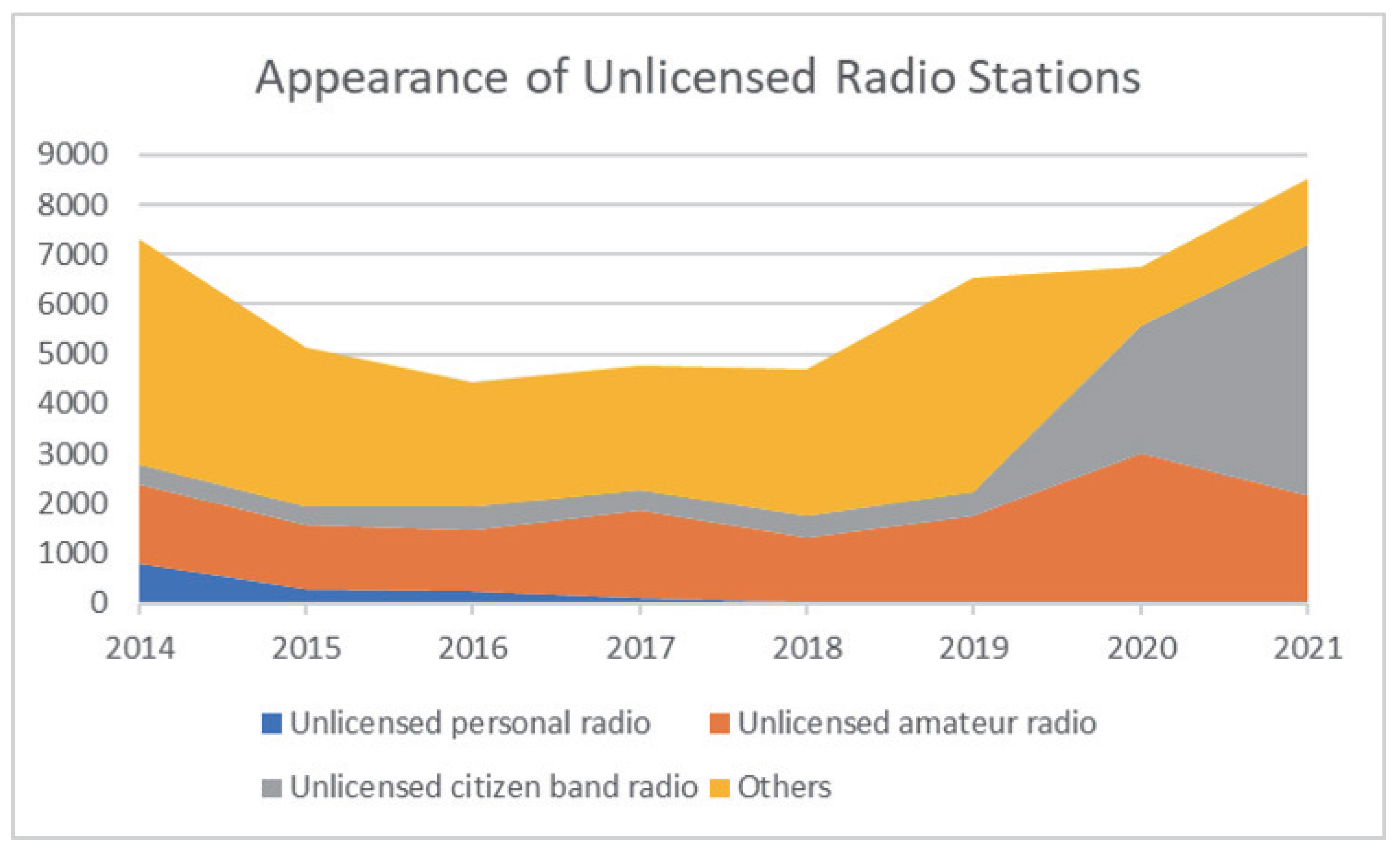
:1. Introduction
- The investigation of a free-path trajectory that helps to further improve estimation accuracy;
- Detailed explanations of each process of our proposed system;
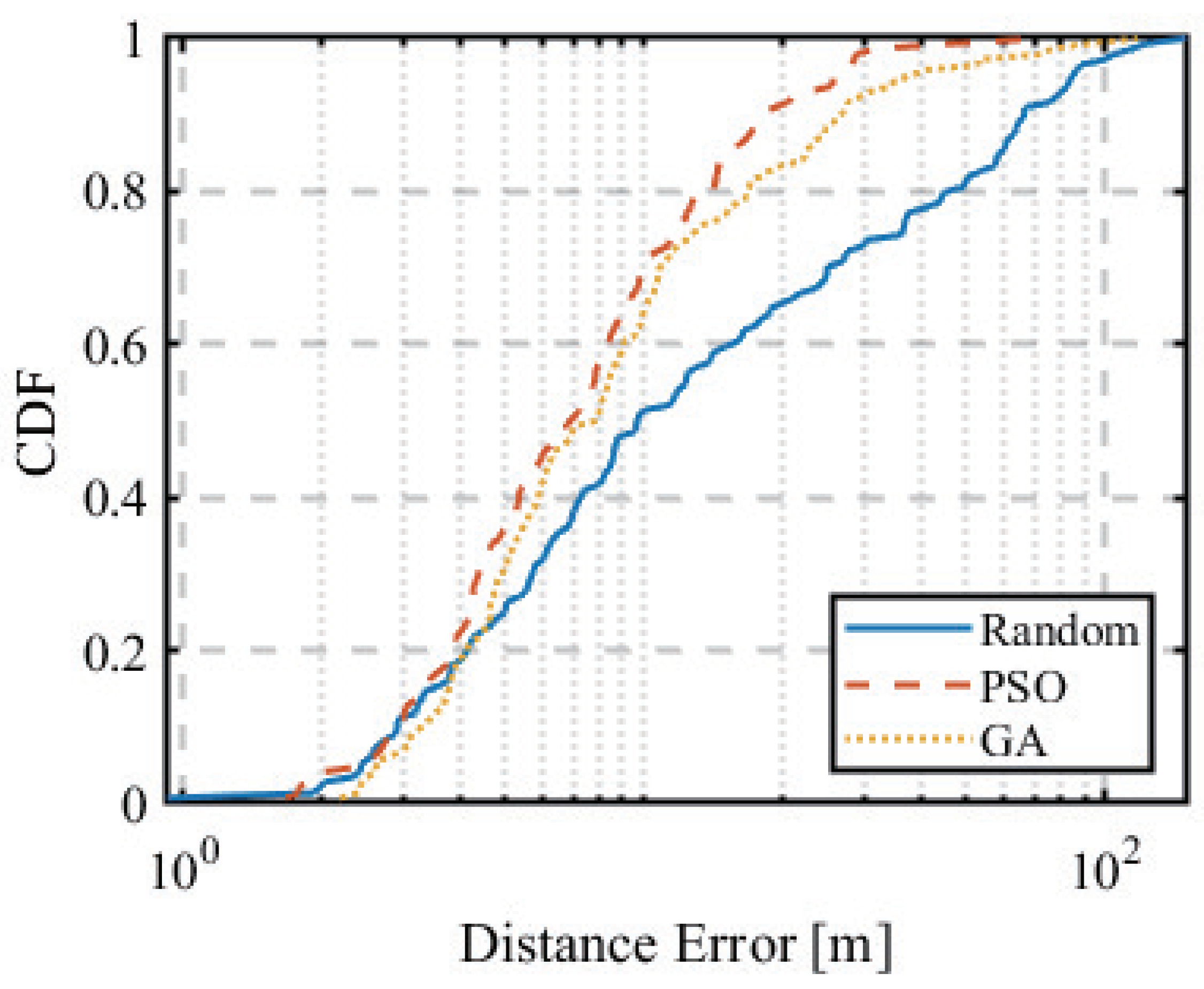
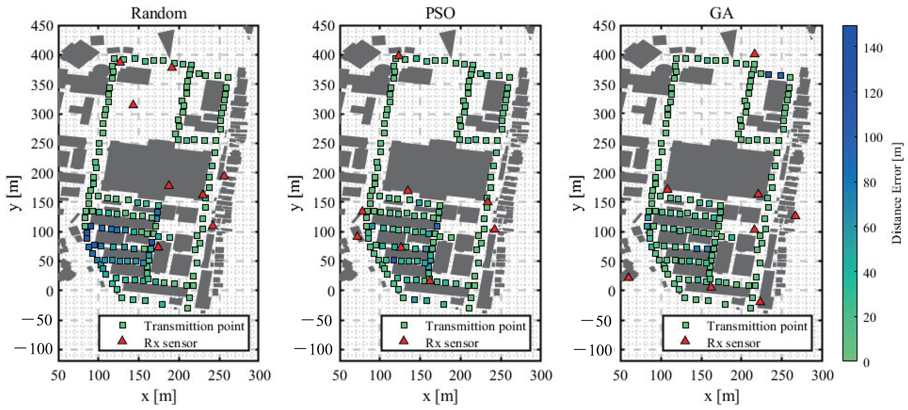
- Comparison of different optimization solving techniques;
- Discussions about future directions/applications of the UAV-based localization system proposed in this paper.
2. Localization Methods
2.1. Localization Methods of Unknown Emitters
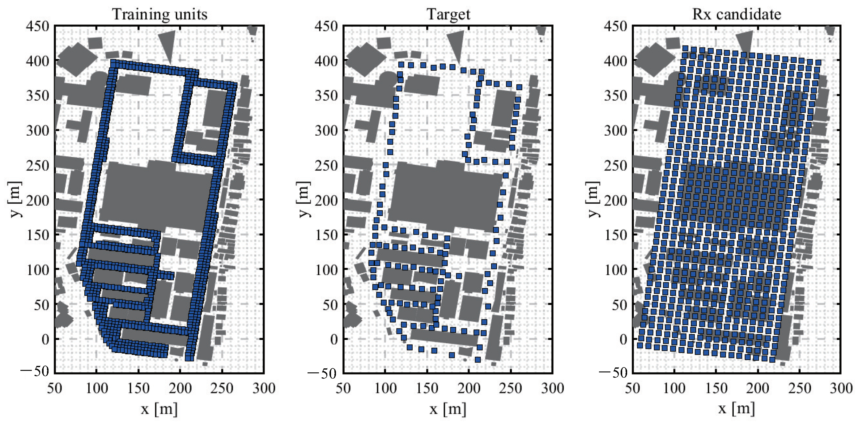
2.2. Fingerprint-Based Localization
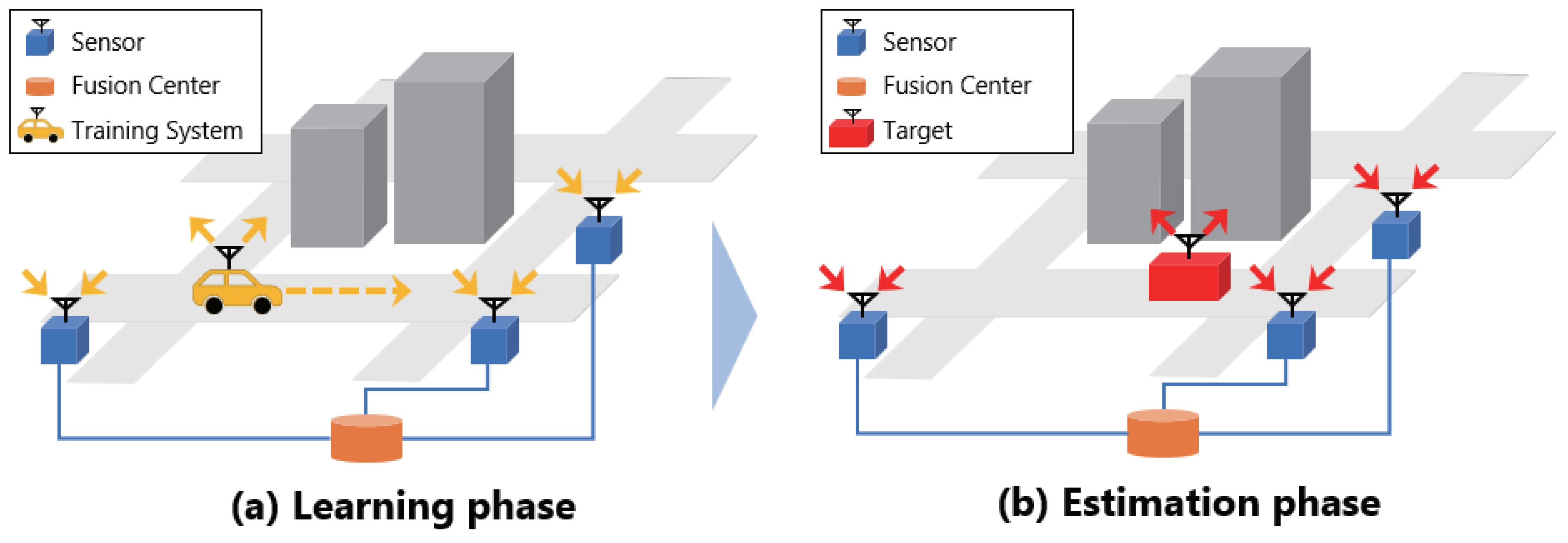
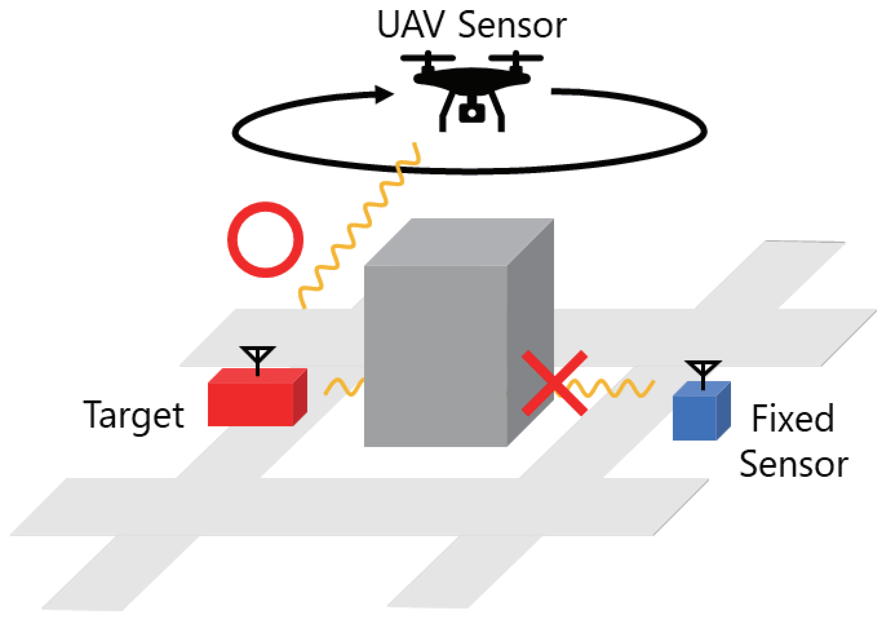
2.3. Use of UAV Sensor
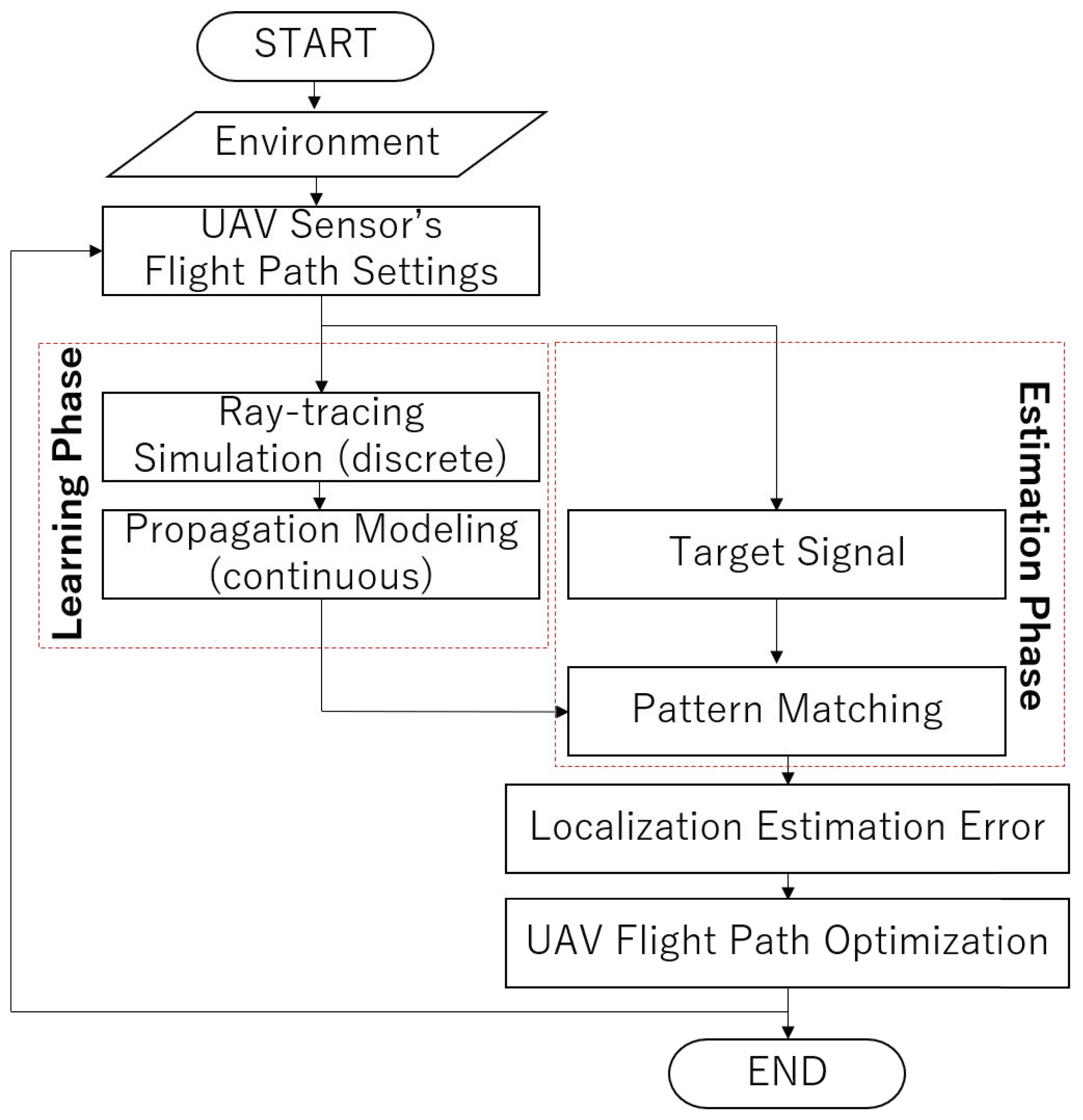
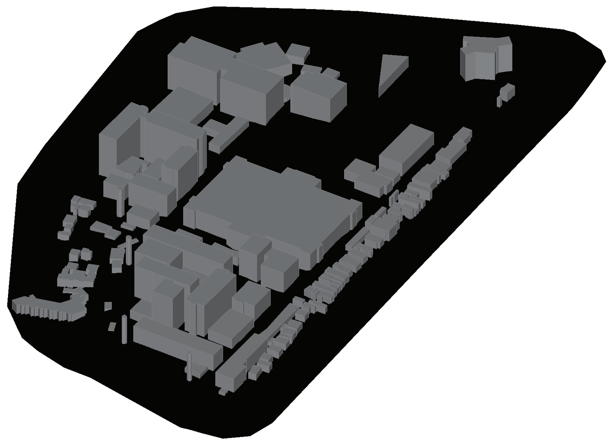
3. Simulation System
3.1. Ray-Tracing Simulation
- It traces radio waves emitted from a transmitting point as rays of light and searches for a path;
- It geometrically calculates paths with reflection, diffraction, and transmission;
- It can take into account multipath effects caused by obstacles;
- It requires much less memory and computation than the FDTD method, a well-known theoretical approach.
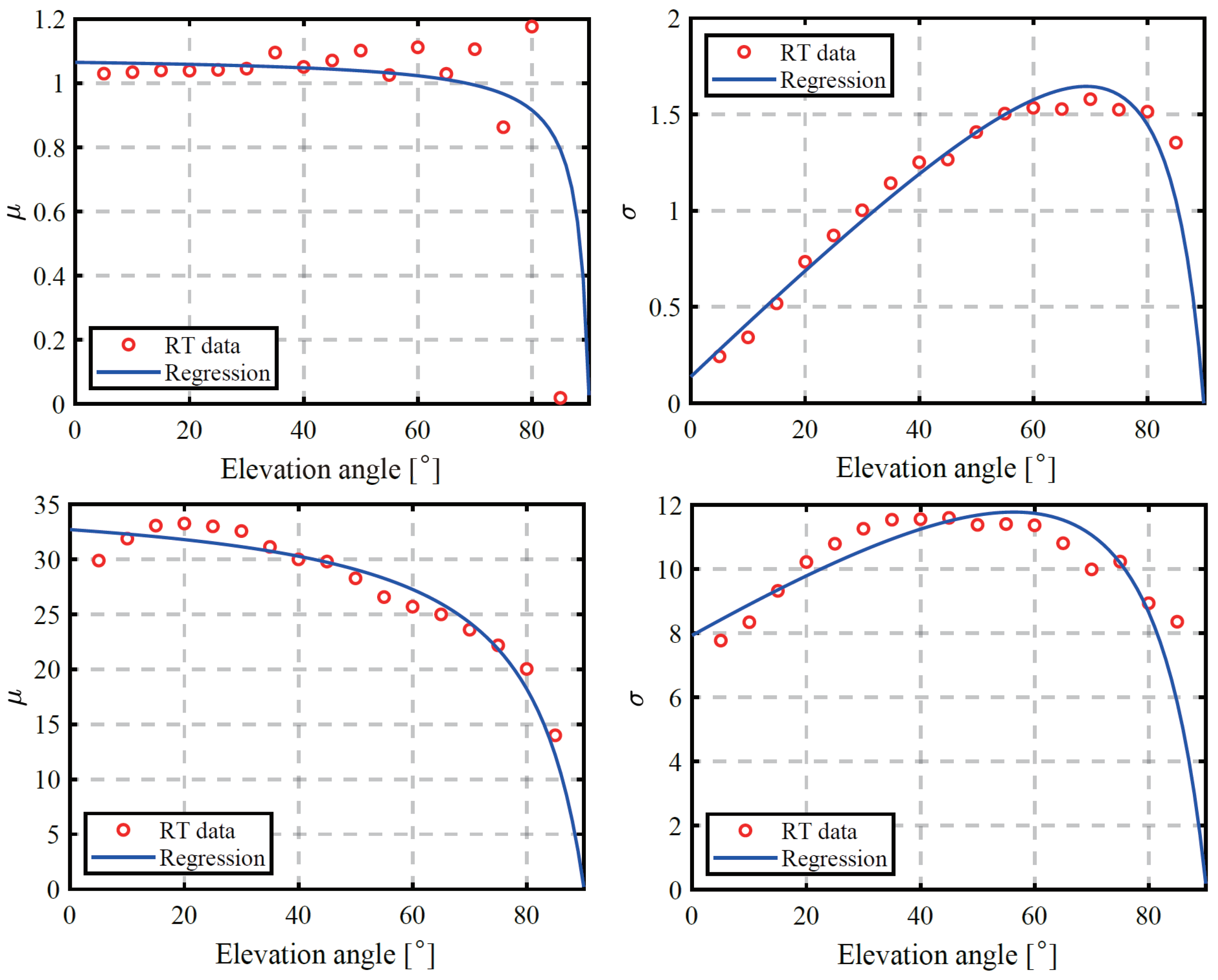
3.2. Propagation Modeling
3.3. LoS Probability
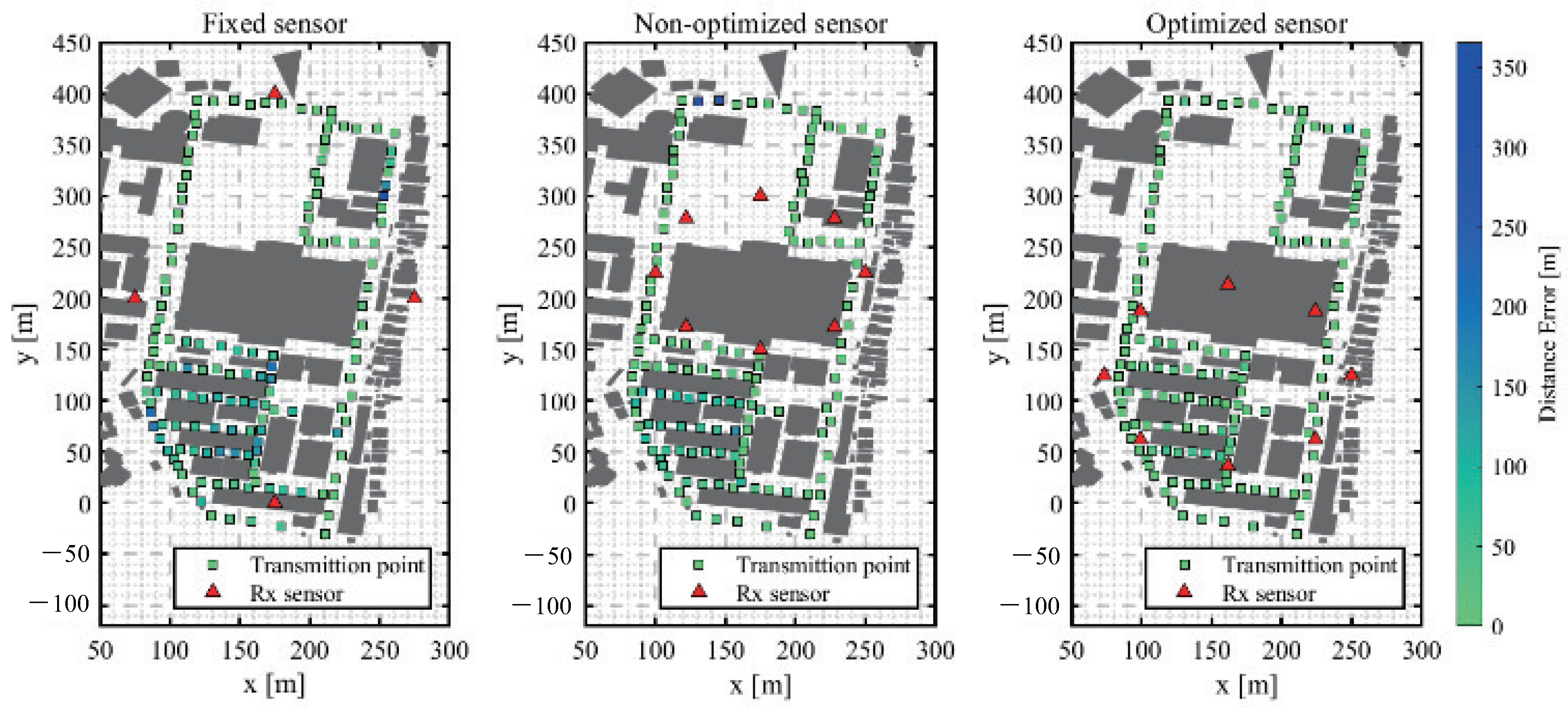
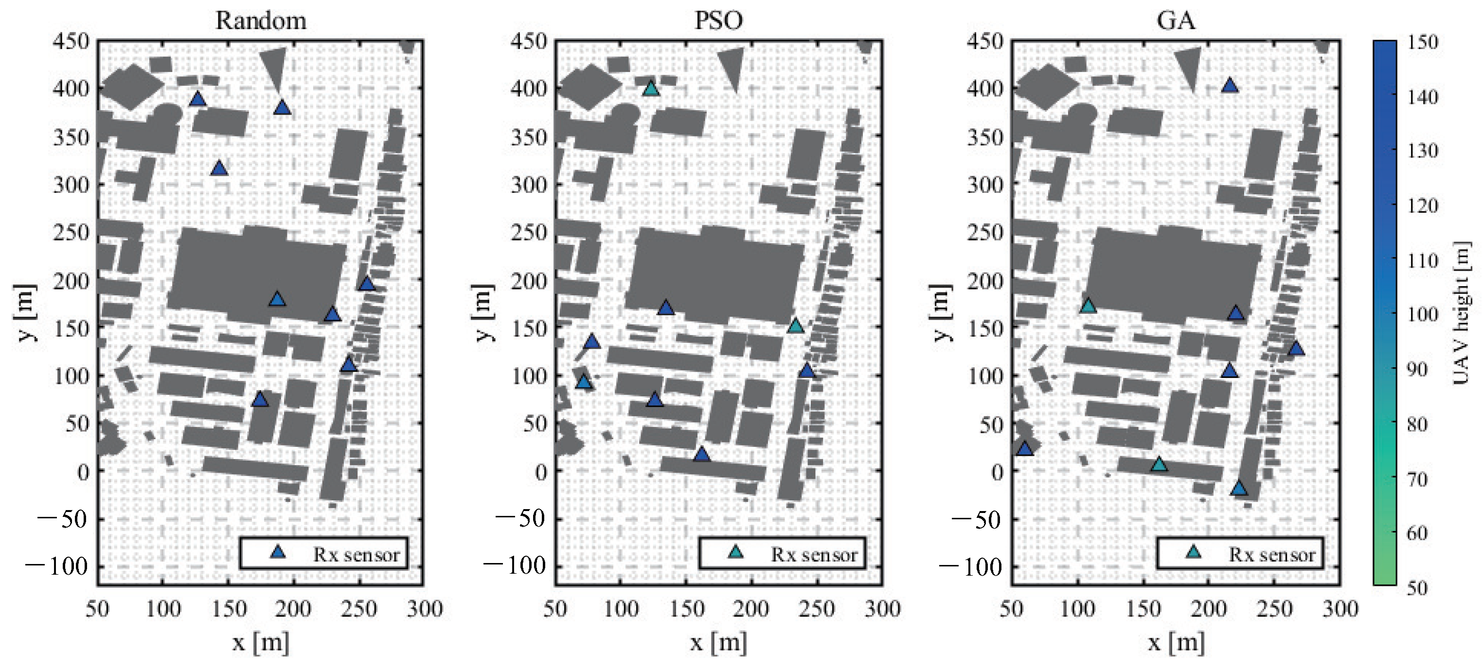
3.4. Optimization of UAV Flight Path
4. Simulation Results
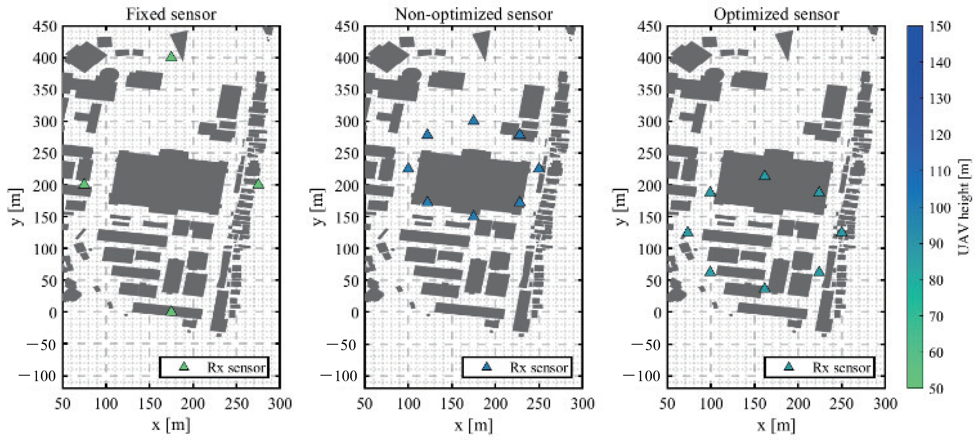
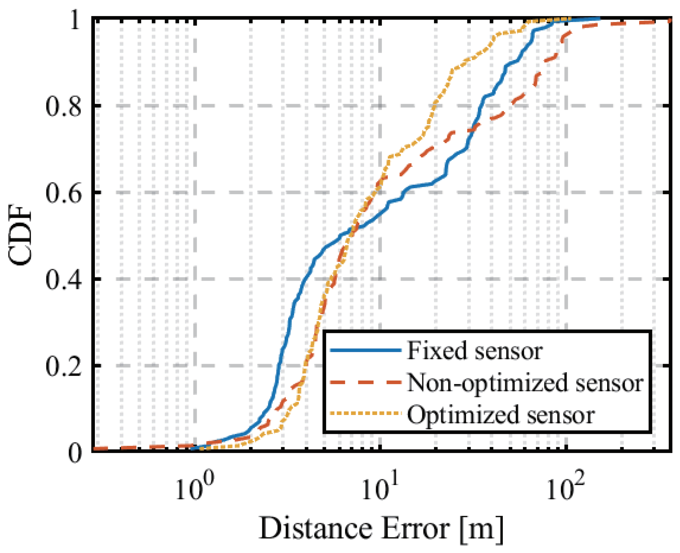
4.1. Circular Orbit Optimization
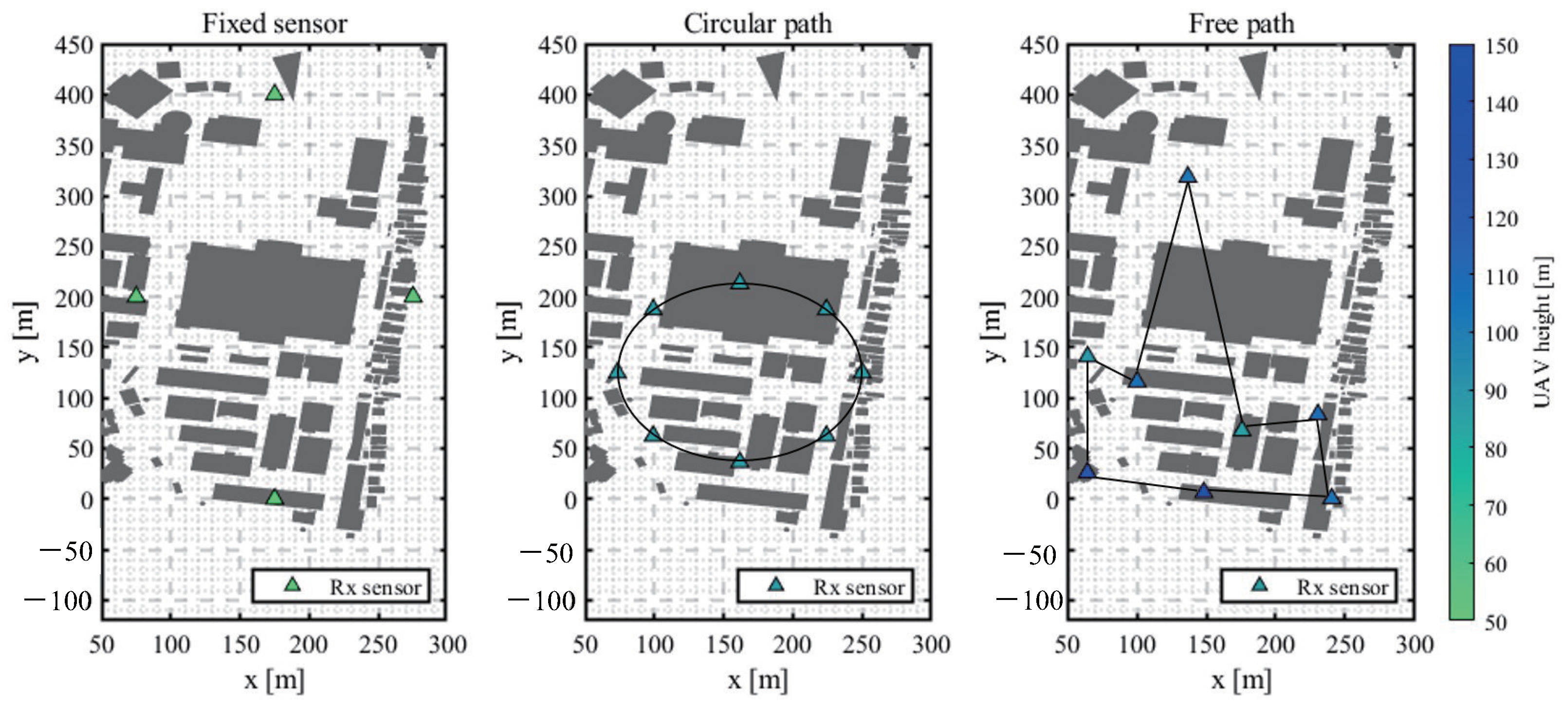
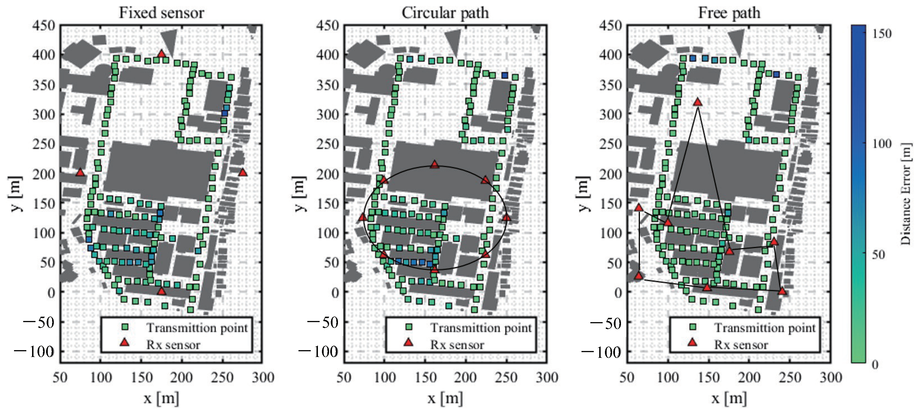
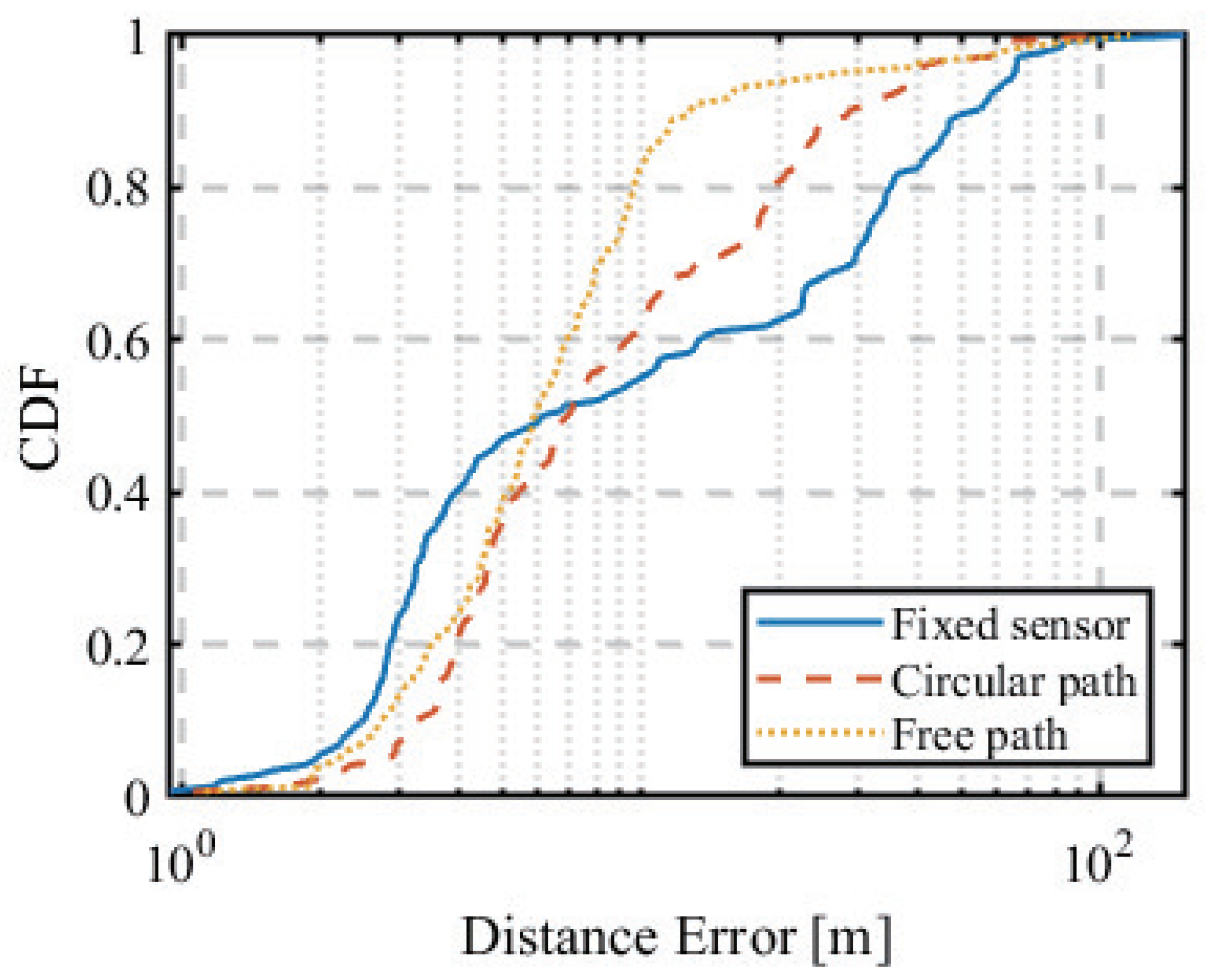
4.2. Non-Circular Orbit Optimization
5. Conclusions
Author Contributions
Funding
Data Availability Statement
Acknowledgments
Conflicts of Interest
Appendix A. Optimization Problem Solving

| Parameter | Value or Property |
|---|---|
| Initial population | |
| Number of genes | 50 |
| Iteration | 10 |
| Generation model | Discrete |
| Selection | Roulette |
| Crossover | One-point crossing |
| Mutation probability | 0.01 |


References
- Farhan, L.; Hameed, R.S.; Ahmed, A.S.; Fadel, A.H.; Gheth, W.; Alzubaidi, L.; Fadhel, M.A.; Al-Amidie, M. Energy Efficiency for Green Internet of Things (IoT) Networks: A Survey. Network 2021, 1, 279–314. [Google Scholar] [CrossRef]
- Ministry of Internal Affairs and Communications Japan DEURAS Direction Finder (DEURAS-D). Available online: https://www.tele.soumu.go.jp/e/adm/monitoring/moni/type/deurasys/deuras_d.htm (accessed on 26 July 2023).
- Witrisal, K. Inclusive Radio Communications for 5G and beyond; Science Direct; Academic Press: Washington, DC, USA, 2021; Chapter 9; pp. 253–293. [Google Scholar]
- Haniz, A. Fingerprint-Based Localization of Unknown Radio Emitters in Outdoor Urban Environments. Ph.D. Thesis, Tokyo Institute of Technology, Tokyo, Japan, 2016. [Google Scholar]
- Yu, T.; Haniz, A.; Sano, K.; Iwata, R.; Kosaka, R.; Kuki, Y.; Tran, G.K.; Takada, J.; Sakaguchi, K. A guide of fingerprint based radio emitter localization using multiple sensors. IEICE Trans. Commun. 2018, 101, 2104–2119. [Google Scholar] [CrossRef]
- Murata, S.; Matsuda, T.; Nishimori, K. Maximum likelihood estimation for single wave source localization using multiple UAVs in NLOS environments. IEICE Trans. Commun. 2022, 105, 229–239. (In Japanese) [Google Scholar]
- Vo, Q.D.; De, P. A Survey of Fingerprint based Outdoor Localization. IEEE Commun. Surv. Tutor. 2015, 18, 491–506. [Google Scholar] [CrossRef]
- Bahl, P.; Padmanabhan, V. RADAR: An in-building RF-based user location and tracking system. In Proceedings of the IEEE INFOCOM 2000, Tel Aviv, Israel, 26–30 March 2000; Volume 2, pp. 775–784. [Google Scholar]
- Li, B.; Wang, Y.; Lee, H.; Dempster, A.; Rizos, C. Method for yielding a database of location fingerprints in WLAN. IEE Proc.-Commun. 2005, 152, 580–586. [Google Scholar] [CrossRef]
- Tanaka, S.; Tran, G.K.; Sakaguchi, K. Outdoor Localization of RF Emitter Using UAV-based Sensors. In Proceedings of the IEICE SmartCom2019, New Brunswick, NJ, USA, 18–20 November 2016. [Google Scholar]
- Kamei, T.; Tran, G.K.; Tanaka, S. Study on the Optimization of Flight Paths for Fingerprint-Based Outdoor Localization Using UAV. In Proceedings of the IEEE PIMRC, Tokyo, Japan, 12–15 September 2022. [Google Scholar]
- Alsheikh, M.A.; Lin, S.; Niyato, D.; Tan, H.P. Machine Learning in Wireless Sensor Networks: Algorithms, Strategies, and Applications. IEEE Commun. Surv. Tutor. 2014, 16, 1996–2018. [Google Scholar] [CrossRef]
- Alzubaidi, L.; Bai, J.; Al-Sabaawi, A.; Santamaría, J.; Albahri, A.S.; Al-dabbagh, B.S.N.; Fadhel, M.A.; Manoufali, M.; Zhang, J.; Al-Timemy, A.H.; et al. A survey on deep learning tools dealing with data scarcity: Definitions, challenges, solutions, tips, and applications. Big Data 2023, 10, 46. [Google Scholar] [CrossRef]
- Tanaka, S. Study on Sensor Positions for Outdoor Localization of RF Emitter Using UAV-Based Sensors. Master’s Thesis, Tokyo Institute of Technology, Tokyo, Japan, 2020. (In Japanese). [Google Scholar]
- Tsuchiya, K. UAV-Based Outdoor Location Estimation Technology Using Time-Series Fingerprinting Method. Master’s Thesis, Tokyo Institute of Technology, Tokyo, Japan, 2022. (In Japanese). [Google Scholar]
- Imai, T. Ray-Tracing Method for Radio Propagation Analysis—Fundamentals and Practical Applications; Corona Publishing Co.: Tokyo, Japan, 2016. (In Japanese) [Google Scholar]
- Haniz, A.; Tran, G.K.; Iwata, R.; Sakaguchi, K.; Takada, J.; Hayashi, D.; Yamaguchi, T.; Arata, S. Propagation Channel Interpolation for Fingerprint-Based Localization of Illegal Radio. IEICE Trans. Commun. 2015, 98, 2508–2519. [Google Scholar] [CrossRef]
- Holis, J.; Pechac, P. Elevation dependent shadowing model for mobile communications via high altitude platforms in built-up areas. IEEE Trans. Antennas Propag. 2008, 56, 1078–1084. [Google Scholar] [CrossRef]
- Kennedy, J.; Eberhart, R. Particle swarm optimization. In Proceedings of the ICNN’95—International Conference on Neural Networks, Perth, Australia, 27 November–1 December 1995. [Google Scholar]
- Shimizu, Y. An Encouragement of Learning Optimization Engineering—Workbench for Smart Decision Making; Corona Publishing Co.: Tokyo, Japan, 2010. (In Japanese) [Google Scholar]
- Saito, T. Particle Swarm Optimizers and Nonlinear Systems. IEICE-ESS Fundam. Rev. 2011, 5, 155–161. (In Japanese) [Google Scholar] [CrossRef]
- Krichen, M.; Adoni, W.Y.H.; Mihoub, A.; Alzahrani, M.Y.; Nahhal, T. Security Challenges for Drone Communications: Possible Threats, Attacks and Countermeasures. In Proceedings of the 2022 2nd International Conference of Smart Systems and Emerging Technologies (SMARTTECH), Riyadh, Saudi Arabia, 9–11 May 2022; pp. 184–189. [Google Scholar]
- Ko, Y.; Kim, J.; Duguma, D.G.; Astillo, P.V.; You, I.; Pau, G. Drone Secure Communication Protocol for Future Sensitive Applications in Military Zone. Sensors 2021, 21, 2057. [Google Scholar] [CrossRef] [PubMed]
- Man, K.F.; Tang, K.S.; Kwong, S. Genetic algorithms: Concepts and applications. IEEE Trans. Ind. Electron. 1996, 43, 519–534. [Google Scholar] [CrossRef]


| Abbreviation | Meanings |
|---|---|
| LoS | Line-of-Sight |
| NLoS | Non-Line-of-Sight |
| UAV | Unmanned Aerial Vehicle |
| PSO | Particle Swarm Optimization |
| GA | Genetic Algorithm |
| RF | Radio Frequency |
| MIC | Ministry of Internal Affairs and Communications |
| DEURAS | Detect Unlicensed Radio Stations |
| DEURAS-D | DEURAS Direction Finder |
| GPS | Global Positioning System |
| RSSI | Received Signal Strength Indicator |
| TDOA | Time Difference of Arrival |
| AOA | Angle of Arrival |
| FDTD | Finite-Difference Time-Domain |
| Tx | Transmitter |
| Rx | Receiver |
| CDF | Cumulative Density Function |
| NNSS | Nearest Neighbour in Signal Space |
| KNN | k-Nearest Neighbour |
| ML | Maximum Likelihood |
| Rx | Antenna type Antenna height (m) | Isotropic 50/75/100/125/150 |
| Tx | Frequency (GHz) | 2.487 |
| Bandwidth (MHz) | 5.00 | |
| Transmit power (dBm) | 27.0 | |
| Antenna type | Isotropic | |
| Antenna height (m) | 2 | |
| Iteration | Reflection | 6 |
| Diffraction | 1 | |
| Penetration | 0 |
| w | Number of Particles | |||
|---|---|---|---|---|
| 0.5 | 100 | 10 |
| Sensor | Average (m) | CDF 90% (m) |
|---|---|---|
| Fixed | 19.69 | 55.02 |
| Non-optimized | 28.18 | 77.96 |
| Optimized | 13.09 | 28.59 |
| Sensor | Average [m] | CDF 90% [m] |
|---|---|---|
| Fixed | 19.69 | 55.02 |
| Circular orbit | 13.09 | 28.59 |
| Non-circular orbit | 9.66 | 12.91 |
Disclaimer/Publisher’s Note: The statements, opinions and data contained in all publications are solely those of the individual author(s) and contributor(s) and not of MDPI and/or the editor(s). MDPI and/or the editor(s) disclaim responsibility for any injury to people or property resulting from any ideas, methods, instructions or products referred to in the content. |
© 2023 by the authors. Licensee MDPI, Basel, Switzerland. This article is an open access article distributed under the terms and conditions of the Creative Commons Attribution (CC BY) license (https://creativecommons.org/licenses/by/4.0/).
Share and Cite
Tran, G.K.; Kamei, T.; Tanaka, S. Route Optimization of Unmanned Aerial Vehicle Sensors for Localization of Wireless Emitters in Outdoor Environments. Network 2023, 3, 326-342. https://doi.org/10.3390/network3030016
Tran GK, Kamei T, Tanaka S. Route Optimization of Unmanned Aerial Vehicle Sensors for Localization of Wireless Emitters in Outdoor Environments. Network. 2023; 3(3):326-342. https://doi.org/10.3390/network3030016
Chicago/Turabian StyleTran, Gia Khanh, Takuto Kamei, and Shoma Tanaka. 2023. "Route Optimization of Unmanned Aerial Vehicle Sensors for Localization of Wireless Emitters in Outdoor Environments" Network 3, no. 3: 326-342. https://doi.org/10.3390/network3030016
APA StyleTran, G. K., Kamei, T., & Tanaka, S. (2023). Route Optimization of Unmanned Aerial Vehicle Sensors for Localization of Wireless Emitters in Outdoor Environments. Network, 3(3), 326-342. https://doi.org/10.3390/network3030016