Article

Challenges in Physical Layer Security for Visible Light Communication Systems

1
Department of Electrical Engineering, Korea Military Academy, Seoul 01815, Korea
2
5GIC&6GIC, Institute for Communication Systems (ICS), University of Surrey, Guildford GU2 7XH, UK
3
Department of Engineering Science, University of Oxford, Oxford OX1 3PJ, UK
*
Author to whom correspondence should be addressed.
Network 2022, 2(1), 53-65; https://doi.org/10.3390/network2010004
Submission received: 18 December 2021 / Revised: 11 January 2022 / Accepted: 19 January 2022 / Published: 20 January 2022

Abstract

:
This article highlights challenges associated with securing visible light communication (VLC) systems by using physical layer security (PLS) techniques. Motivated by the achievements in PLS studies for radio frequency (RF) communication, many PLS techniques for VLC systems were also rigorously investigated by tailoring the RF techniques to the VLC environment. However, careful consideration of the inherent differences between RF and VLC systems is still needed. By disregarding these differences, an eavesdropper could be given an opportunity to wiretap the VLC systems, even when PLS techniques are employed to protect them. Crucially, the fact that it is often not possible to know the number and locations of eavesdroppers in real VLC systems may allow eavesdroppers to devise various cooperative eavesdropping methods. By examining a few examples of the possible eavesdropper threats that can occur in VLC systems, this article offers novel insights into the vulnerabilities of state-of-the-art PLS schemes for VLC systems. Although the focus of the paper is mostly on these weaknesses, some potential solutions are also briefly proposed with a view to stimulating discourse in the community.

1. Introduction

Over the past few decades, the acceleration of the development of mobile devices, such as smart-phones, tablet computers, wearable devices, and Internet of Things devices, provoked a higher demand for data traffic via wireless communication. However, traditional radio frequency (RF) communication systems, such as WiFi and cellular networks, face difficulties in satisfying the requirements of future networks due to the scarcity of RF spectrum. Thus, there is a need for a new air interface and/or more spectrum to offload the high volume of wireless traffic. As a possible solution, visible light communication (VLC) gained considerable popularity in academia and industry. VLC utilizes visible light, the spectrum of which ranges from 400 THz to 700 THz and is license free; hence, VLC can be exploited for high-speed indoor wireless communication [1].
VLC offers additional advantages. On the one hand, since visible light cannot penetrate an opaque wall, a VLC system can offer high security at the physical layer. However, in large open spaces, such as libraries, open-plan offices, and conference halls, it is still possible for a malicious user to eavesdrop a VLC transmission. Although an authentication process similar to Wired Equivalent Privacy (WEP) and WiFi Protected Access (WPA) would be possible even for a VLC system, such a method imposes large signaling and computational overhead and was shown to be breakable [2]; thus, it would not be secure.
As one of many network security approaches, physical layer security (PLS) is a set of techniques that enables a transmitter and a legitimate receiver to securely communicate by utilizing the randomness of the channel between the transmitter and the receiver [3,4]. PLS can be deemed to be the most secure method of communicating, since security in this context is provable (in the information theoretic sense). For example, in a typical wiretap model, PLS theory intimates that secure communication is possible when the capacity of the intended communication channel is higher than that of the eavesdropping channel.
In RF systems, various PLS transmission techniques that allow better signal reception at an intended receiver by utilizing multiple antennas were proposed, and their information-theoretic security performances were analyzed [5]. Also, motivated by the PLS schemes of the RF systems, numerous variants of PLS techniques securing indoor VLC systems were also proposed, such as zero-forcing, robust beamforming, artificial jamming, and light emitting diode (LED) selection, generalized space shift keying (GSSK) modulation, etc. [6,7,8,9,10,11,12,13,14]. Yet many intrinsic characteristics of VLC systems are different from RF systems (e.g., the channel, physical properties of the transmitting and receiving devices, and the signal constraints). Hence, it is necessary to take these differences into account when tailoring PLS techniques to VLC systems. A number of investigations considered these unique properties. For example, [7] studied the achievable secrecy rates under constraints on the input signal amplitude for single-input single-output (SISO) and multiple-input single-output (MISO) scenarios and [9] considered various input signal distributions to increase the secrecy rate.
Fundamental investigations of PLS typically treat a model whereby a single active jamming device or passive eavesdropper is present in the system, and the location and/or channel properties associated with the third-party device are assumed to be known. In reality, it may be the case that the locations and number of eavesdropping devices are not known. Recent studies in [11,12] began to address this scenario, where unknown eavesdropper locations are modeled by using tools from stochastic geometry. Furthermore, VLC eavesdroppers use different receiver architectures than legitimate users in an effort to intercept the signal. The physical features of the VLC transceiver components enable the eavesdropper to augment its receiver capability and overcome many of the existing PLS techniques.
In light of the current state-of-the-art in VLC technology, this article presents several challenges and open problems in securing indoor VLC systems at the physical layer. The main goal of this article is to argue that the majority of PLS studies for VLC undertaken in recent years were considering naive assumptions that excessively favor the system designer and to offer novel insights into the vulnerabilities of current PLS schemes for VLC systems. In Section 2, we begin by explaining the fundamental differences in the security environments in RF and VLC systems. In Section 3, a few examples showing that an eavesdropper can break existing PLS techniques are examined. We offer thoughts on future directions and conclusions in Section 4 and Section 5, respectively.

2. Differences in RF and VLC Security Environments

PLS can be split into the two main categories. The first is transmitting a message with a well-designed coding technique that allows appropriate redundancy so that only the legitimate user can reliably decode the message, while introducing enough randomness so that an eavesdropper experiences large ambiguity when attempting to decode the message. The second is generating and distributing a secret key between a transmitter and an intended user by utilizing the distinct physical characteristics of their reciprocal channel [3].
The two assumptions that the latter PLS category requires—i.e., the reciprocity and the uncorrelatedness of the channel—are challenging to achieve in indoor VLC systems. First, the reciprocity of the channel between a transmitter and a legitimate user’s receiver should be achieved so that they can extract a secret key from the shared channel state information (CSI). However, unlike in RF systems where a single antenna can act as a transmitter and a receiver, in VLC systems, the transmitter and receiver are distinct components, that is, they consist of an LED and a photodiode (PD), respectively. Hence, the reciprocity can hold only when the LED and PD are located at the same place or are in very close proximity and the characteristics of LED and PD for the uplink and downlink are identical. In reality, these are impractical restrictions for indoor VLC systems. Furthermore, an uplink transmission with visible light is undesirable, since the light radiating from the user devices would cause a visual disturbance to users; thus, RF or infrared communication is typically considered for the uplink transmissions. For these reasons, sharing a secret key between a transmitter and a legitimate user by using channel reciprocity is not a natural assumption in VLC systems.
Second, the fact that fading does not exist in VLC systems, since the PD’s detector area is much larger than the wavelength of visible light, precludes the channel for the intended link from being uncorrelated with that of the eavesdropper. Therefore, instead of studying secret key agreement techniques, the majority of existing PLS studies for VLC systems focused on the former key-less techniques, which require that the legitimate user should retain a superior channel relative to that of the eavesdropper to achieve a positive secure transmission rate.
In VLC systems, it might be difficult for a legitimate user to achieve a higher signal-to-noise ratio (SNR) than that experienced by an eavesdropper, which imposes challenges on developing PLS techniques. The SNR is typically determined based on the strength of a received desired signal and noise introduced at a receiving device. Thus, in RF systems, to facilitate a higher SNR at a legitimate user, a transmitter with multiple antennas can enhance the strength of the received signal only at a legitimate site by, for example, utilizing beam-steering transmission, antenna selection, or artificial jamming strategies. An eavesdropper in RF systems does not have many options to increase its SNR under these PLS transmission schemes, except to reduce the noise generated in its electronic circuitry and antenna(s), which is technically limited to some extent. Although an RF eavesdropper with multiple antennas is capable of increasing its SNR and somewhat reducing the secrecy rate, it was shown that it is highly challenging to achieve a higher SNR than that of a legitimate user when suitable multiantenna techniques are employed [15].
In VLC systems, considering the channel model of visible light in [16], the eavesdropper can significantly augment its receiver capability by implementing possible device modifications, such as increasing the area of the PD, adopting a high-gain optical lens, and accurately adjusting the receiver’s orientation toward the LED transmitter. The legitimate user can also increase its receiver sensitivity using these methods. However, the legitimate user must consider different constraints on hardware requirements, user convenience, communication efficiency, etc., of various applications, which limit the gain of the legitimate user. On the other hand, eavesdroppers can ignore these issues, since its primary goal is eavesdropping. Moreover, the LED transmitters should be spatially distributed over the ceiling to illuminate the entire room evenly. This system design requirement enables the eavesdropper to selectively receive a light signal being emitted from a particular LED by modifying its receiver’s field-of-view (FoV) and adjusting its orientation, avoiding beamforming and jamming interference, which will be discussed in more detail in Section 3.2. Thus, in PLS-enabled VLC systems, an eavesdropper with an additional improvement and/or modification on its receiver architecture may be able to achieve a higher SNR than the legitimate user.
Overall, the differences in the security environments between RF and VLC systems, summarized in Table 1, impose an additional challenge to secure the VLC transmission. Most of the previous PLS studies for VLC systems proposed various transmission techniques and verified their excellent secure communication performance. However, if the eavesdroppers attempt more intelligent approaches to enhance reception, state-of-the-art PLS techniques can be easily avoided and secure communication performance could be degraded significantly.

3. Vulnerabilities of Physical Layer Security in VLC Systems

We now present a few examples to more clearly explain possible vulnerabilities of existing PLS schemes in VLC systems. Specifically, we study three examples showing that well-known PLS transmission techniques—i.e., beamforming, artificial jamming, and LED selection—can be overcome by artful eavesdropper behavior.
In PLS theories, the secrecy capacity C s is a fundamental metric relating to the maximum rate a transmitter can send to satisfy the reliability and secrecy [3]. The secrecy capacity is defined as
C s = max p X ( I ( X ; Y ) I ( X ; Z ) ) )
where I ( · ; · ) denotes the mutual information. Also, p X is the input distribution on the transmitted signal X at the transmitter, and Y and Z denote the signals observed at the legitimate user and the eavesdropper, respectively. On the other hand, when the instantaneous CSI of an eavesdropper is not available at the transmitter, while only its statistical information is possible, a secrecy outage probability (SOP) is used as a primary security performance metric instead of the secrecy capacity [17]. The SOP is defined as the likelihood that the instantaneous secrecy capacity C s is less than a threshold value C th , i.e., P S O = P C s C th . Since this paper discusses the secrecy performance in the presence of a passive eavesdropper whose CSI is assumed to be unavailable at the transmitter, we utilize the SOP (with setting C th = 0 ) to measure the secrecy performance in the following subsections.

3.1. Beamforming

Beamforming strategies are popular methods to improve the secrecy performance in RF systems. The transmitters take the CSI of receivers into account in transmitting the information signals such that the waveforms reach only the UE sites with a high SNR, while suppressing the information signals elsewhere, especially at electron device (ED) sites [18]. Various beamforming approaches were also rigorously proposed and studied for VLC systems to increase secrecy by tailoring RF beamforming to VLC environments; however, the VLC beamforming schemes retain weak points that an ED might exploit. This section explains the VLC beamforming’s weakness in the simultaneous presence of active and passive EDs by explaining the ZF (zero-forcing) beamforming [6] as an example.
ZF precoding is a well-known and practical PLS transmission technique in VLC systems that eliminates information reception at an unintended user by carefully designing the precoding matrix. ZF was shown to effectively decouple a legitimate user from possible malicious users and significantly improve various security measures. More specifically, according to [6], the precoding matrix can be designed to lie in the nullspace of the eavesdropper’s channel. In this case, multiple LED transmitters multiply a data signal by the precoding matrix before transmitting, which can force the reception of the unintended user to zero. Therefore, the achievable secure communication rate under ZF can be almost equal to the achievable rate of the intended user’s point-to-point channel.
However, ZF has limitations with regard to feasibility and performance. First, due to intrinsic condition that the LED transmitters have to retain the CSI of both the legitimate user and malicious users, ZF cannot cope with the threat of unknown passive eavesdroppers (i.e., their CSI is not known to LEDs), which limits the practical use of this approach.
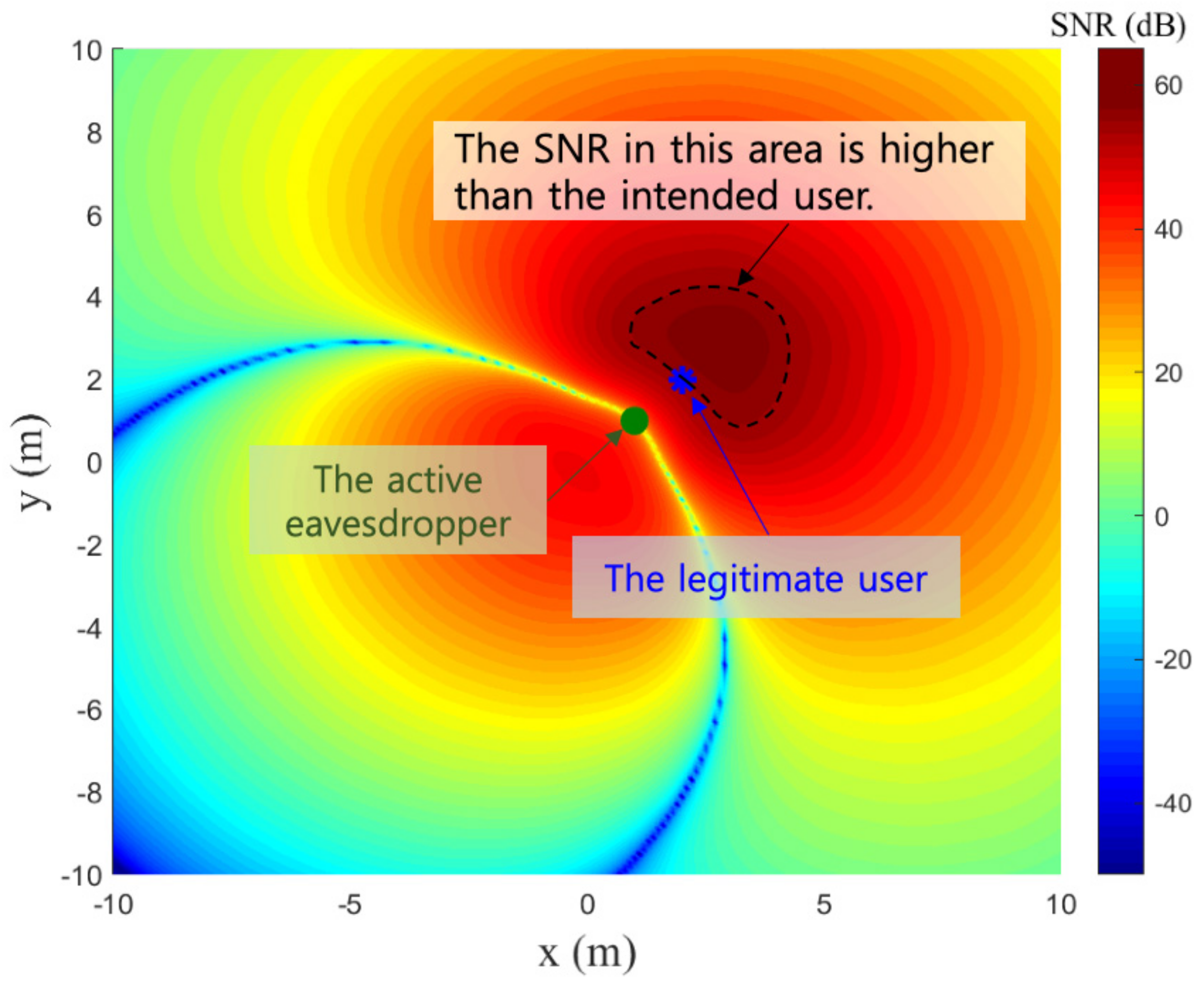
Second, ZF can make the VLC system more vulnerable when passive eavesdroppers are present together with an active eavesdropper whose CSI is known, as illustrated in the example in Figure 1. The figure shows the SNRs according to the receiver location when ZF is adopted. A 10 × 10 transmitter array is assumed to consist of uniformly distributed LEDs on a square lattice in a room of dimension 20 × 20 m 2 . One legitimate user and one active eavesdropper are assumed to be present. These receivers are marked with blue and green dots in the figure. Also, multiple passive eavesdroppers are assumed to be distributed according to a Poisson point process (PPP) with the density λ E .
In Figure 1, even when the active eavesdropper is located close to the legitimate user, ZF effectively minimizes the information reception at the active eavesdropper site by utilizing precoding. From this result, ZF appears to secure the transmission against the eavesdropper. However, from the perspective of the passive randomly located eavesdroppers, as shown in Figure 1, it is possible to achieve a higher SNR than the legitimate user. Note that if any passive eavesdropper is located in the dashed area in Figure 1, it can achieve a higher SNR than the legitimate user. Although ZF precoding can minimize the SNR at the active eavesdropper site, ZF precoding for the nearby eavesdropper expands the dashed area in which the SNR is higher than that of the legitimate user. This vulnerability comes from the fact that the ZF design purely aims at forcing the active eavesdropper’s SNR to zero without consideration for the legitimate user’s SNR (or, indeed, SNRs of other unknown receivers in the area).
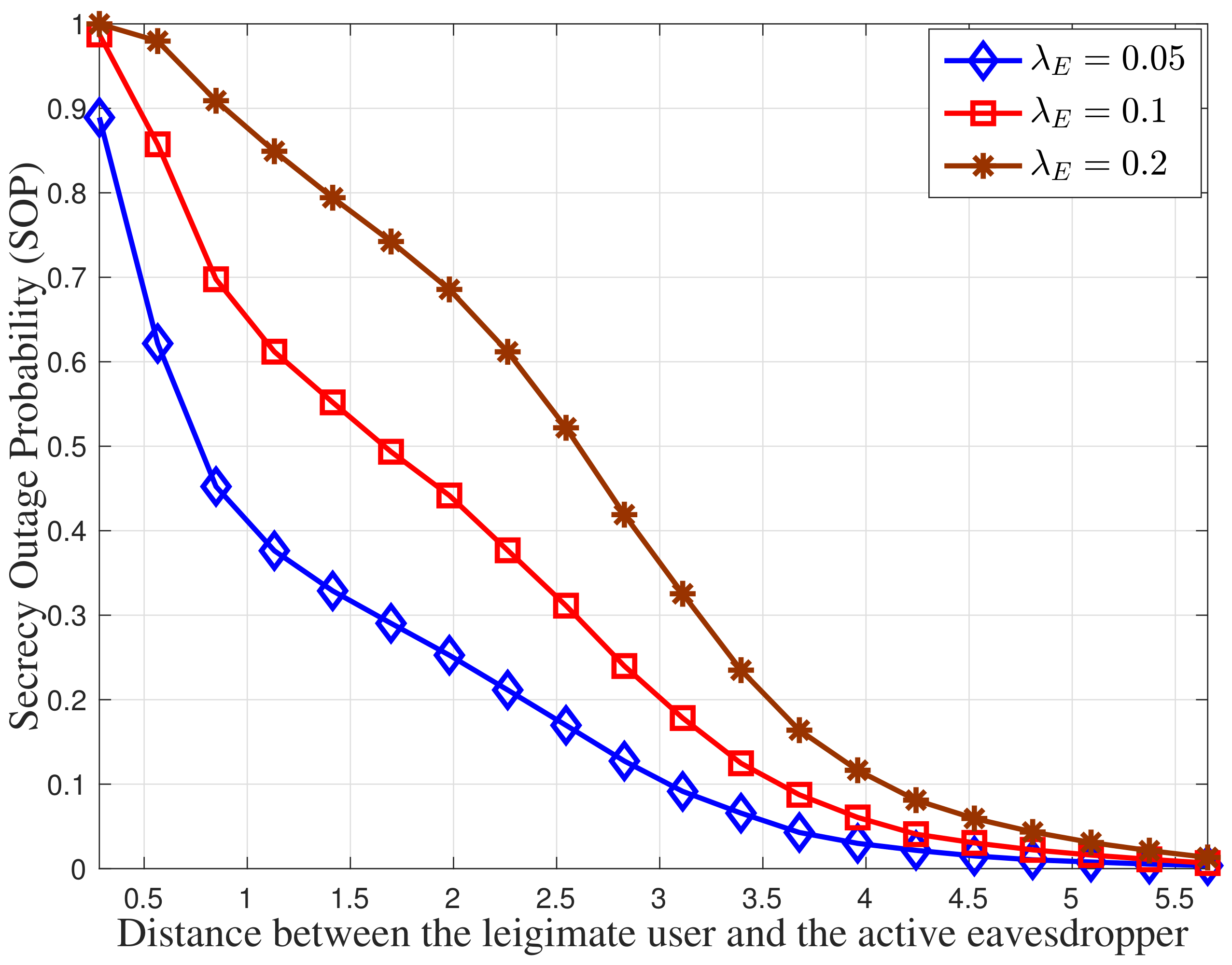
Figure 2 verifies the vulnerability of ZF by depicting the secure outage probability (SOP) as a function of the distance between the legitimate user and the active eavesdropper. Note that a secure outage occurs only when one or more passive eavesdroppers can decode the transmitted message; while the SNR of the active eavesdropper is minimized by the ZF precoder. As the active eavesdropper approaches the legitimate user, the SOP increases, indicating that ZF precoding presents more wiretap opportunities to passive eavesdroppers located in the region.
Our recent work [13] proposed an enhanced ZF beamforming scheme to mitigate the weakness from the presence of active and passive eavesdroppers; however, it cannot entirely eliminate the dashed area in which the eavesdroppers can achieve higher SNR. To the author’s best knowledge, this weakness is inevitable due to the VLC’s intrinsic characteristics that fading does not exist and that a received SNR mainly depends on the geometric properties of the transmitter and receiver.

3.2. Artificial Jamming

In reality, since an eavesdropper should escape the vigilance of a legitimate user or a network manager, it should strive for concealment while eavesdropping the transmission. However, since the channel gain in VLC systems largely depends on the distance between the transmitter and the receiver, the eavesdropper must be located in close proximity to the LED transmitter that serves the target user, thus risking being detected. Alternatively, the eavesdropper can augment its receiver sensitivity by, for example, increasing an area of its PD, adopting a high-gain optical lens, or directing its orientation toward the LED transmitter. These modifications can allow the eavesdropper to achieve a higher SNR even when located at a significant distance from the target user. For example, in [19], a telescope was used to increase the gain of the receiver in an experimental test, and the VLC transmission was successfully eavesdropped a large distance from the transmitter. On the other hand, to cope with an eavesdropper equipped with a better receiver than the intended user, various artificial jamming strategies for VLC systems were proposed [8,9,11,20]. The jamming strategy was shown to be a powerful and practical approach to secure VLC systems, particularly against eavesdroppers with enhanced receiver architectures, since it would be impossible to distinguish between the information and jamming signals.
On the other hand, two intrinsic properties of VLC systems enable eavesdroppers to overcome the jamming strategy. The first is that the multiple LED transmitters must be spatially distributed to illuminate the entire room evenly within the lighting standards, and the second is that the channel gain in VLC systems largely depends on the distance between the transmitter and the receiver. These two properties lead the jamming strategies to perform in a way that the LEDs near to the intended user emit the information, while the distant LEDs emit the jamming signals [11]. In other words, unlike RF systems, the eavesdropper can anticipate which LED performs as either an information transmitter or a jammer, and selectively receives only the information signal, excluding the jamming signals, by narrowing the receiver FoV and accurately aligning the receiver’s orientation toward the target LED transmitter. Note that, in RF systems, multiple antennas being positioned at the same location simultaneously emit the information and jamming signals, which contrasts significantly with the VLC case.
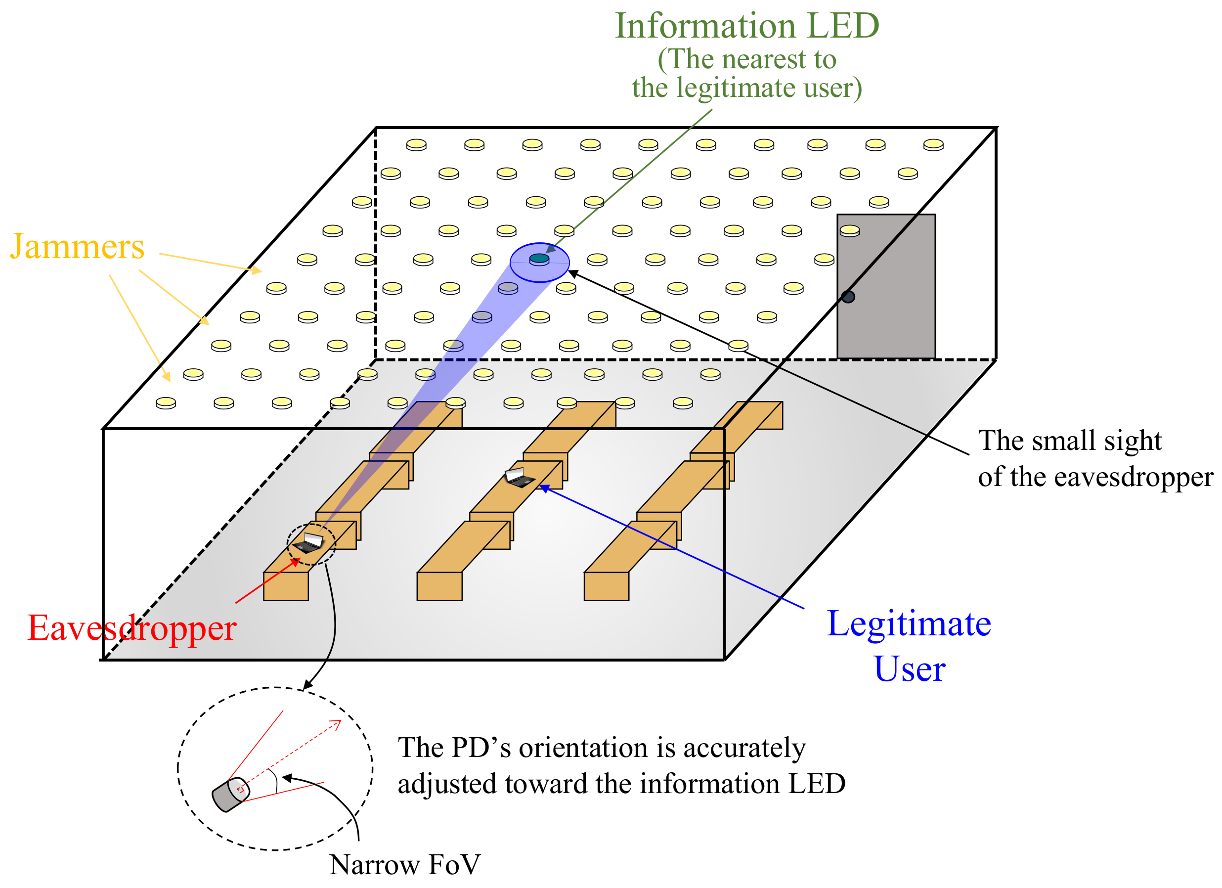
Figure 3 illustrates an example that an eavesdropper narrows its FoV and attempts to wiretap an information-bearing signal while minimizing the reception of jamming signals. In the figure, N T LEDs are assumed to be uniformly distributed on a square lattice in a room of 20 × 20 m 2 , and one legitimate user and one eavesdropper are supposed to be positioned in the region. The nearest LED to the legitimate user is chosen to transmit the information-bearing signal, while all the other LEDs act as jammers. Also, it is assumed that the transmitters know the CSI of both the intended and malicious users. According to [8], the jammers obtain the precoding matrix by designing an optimization problem that maximizes the jamming signal reception at the eavesdropper while aligning it to the null space of the legitimate user’s channel. Then, the jammers multiply a random noise signal by the precoding matrix and transmit it to hinder information reception at the eavesdropper site.
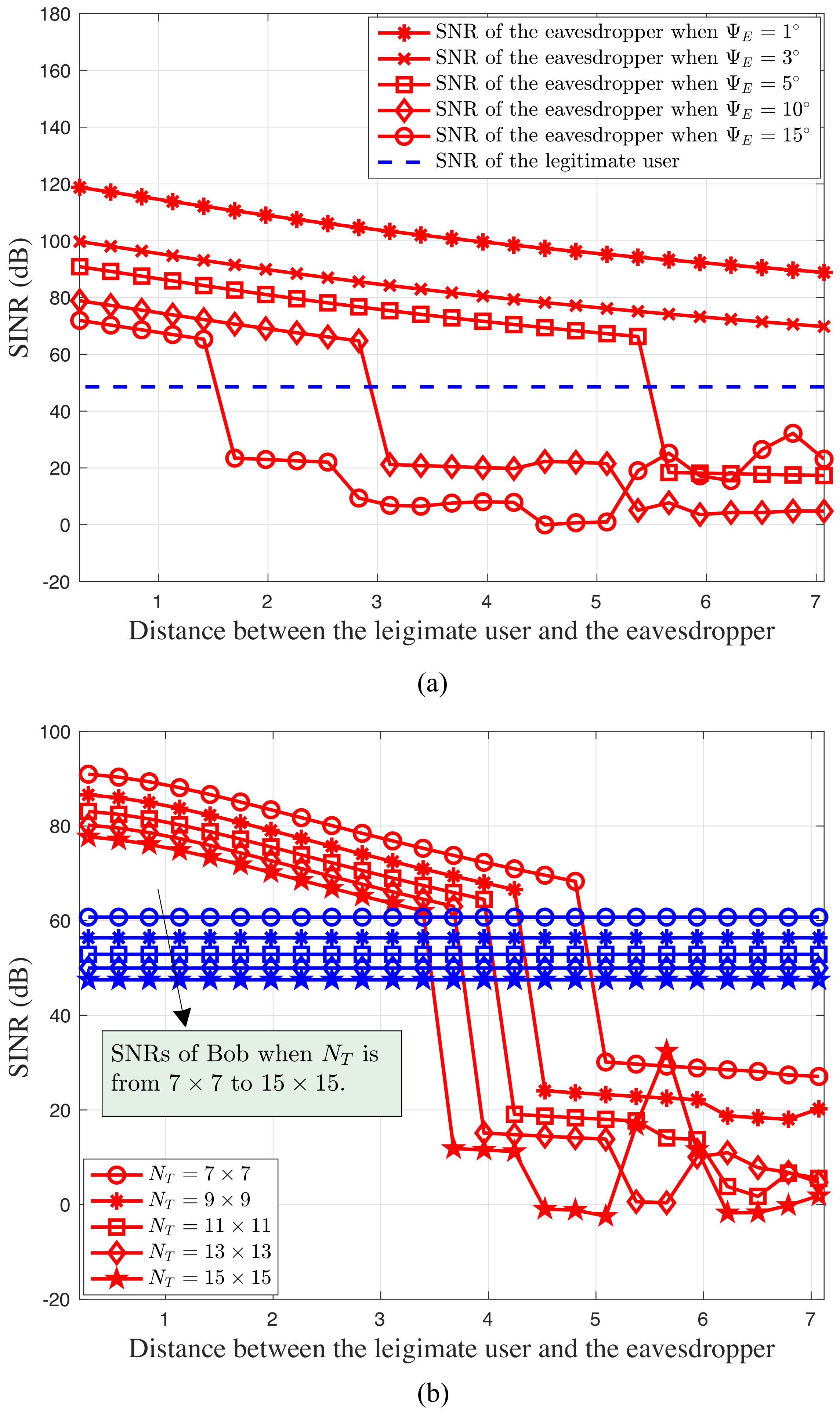
Figure 4 shows the results from numerical experiments that simulate the signal-to-interference-plus-noise ratio (SINR) for the scenario explained in Figure 3. Figure 4a shows the SINR as a function of the distance between the legitimate user and the eavesdropper for different eavesdropper FoVs ( Ψ E ) . We note that the eavesdropper with a narrow FoV can effectively exclude the jamming signals and achieve a higher SINR than the legitimate user when the eavesdropper is located not too far from the legitimate user. According to the VLC channel gain model [16], a receiver equipped with an optical concentration lens with a narrower FoV would yield a better receiver sensitivity. Therefore, the eavesdropper can achieve a higher SINR than the legitimate user to exclude the jamming signal even at a further distance. Also, Figure 4a shows that as the FoV becomes narrower, the eavesdropper can exclude the jamming signal at a further distance. For example, the eavesdropper with Ψ E = 15 should be within 1.4 m of the legitimate user to exclude the effects of the jamming signal. But, an eavesdropper with a narrower FoV, e.g., Ψ E = 5 , can wiretap the transmission as far as 5.4 m from the legitimate user. In contrast, when the eavesdropper fails to exclude the jamming signals due to the extended sight of its PD, the eavesdropper’s SINR suddenly drops.
On the other hand, Figure 4b gives an insight into how one might cope with an eavesdropper with a narrow FoV. The figure shows the SINR for the different numbers of transmitters as a function of the distance between the legitimate user and the eavesdropper. Note that, to maintain a constant level of illumination (even with different numbers of LEDs), we fix the total optical power emitted from the LED array by reducing or increasing the optical power of each LED for the different sets of results. As the number of LEDs increases within a fixed geometry, the distances among the LEDs decrease, which allows the information transmitter and the jammer to be located closer to each other. Therefore, it would be more difficult for the eavesdropper to exclude the jamming signal by using its narrow FoV receiver. More specifically, as shown in the figure, when N T = 7 × 7 and the nearest distance between the information transmitter and the jammers is 2.86 m , the eavesdropper with Ψ E = 10 can wiretap the information as long as it is positioned within 4.8 m of the legitimate user; yet, when the LED array size is increased to N T = 15 × 15 , the eavesdropper must be positioned within 3.4 m of the legitimate user to intercept the signal (i.e., to achieve a higher SINR). The nonmonotonic results for the long distances between the legitimate user and the eavesdropper are due to the design of the jamming precoding strategy, which is optimized such that the eavesdropper that has the same receiver properties as the legitimate user experiences a high degree of jamming. However, for an eavesdropper with different receiver properties—i.e., narrow FoV aligned with the information LED—jamming is not optimized and instead depends upon geometric factors related to the eavesdropper position relative to the neighboring LEDs.

3.3. Cooperative Eavesdroppers in Multiuser VLC Systems

VLC offers the option of dense spatial reuse due to the fact that visible light cannot penetrate an opaque wall and decays quickly with distance. These features enable VLC systems to serve many users simultaneously with high data rates and short time delays. Thus, various PLS transmission techniques for multiuser VLC systems were proposed [21,22]. These works have shown that the PLS can effectively secure VLC transmissions in the presence of either active or passive eavesdroppers under certain conditions.
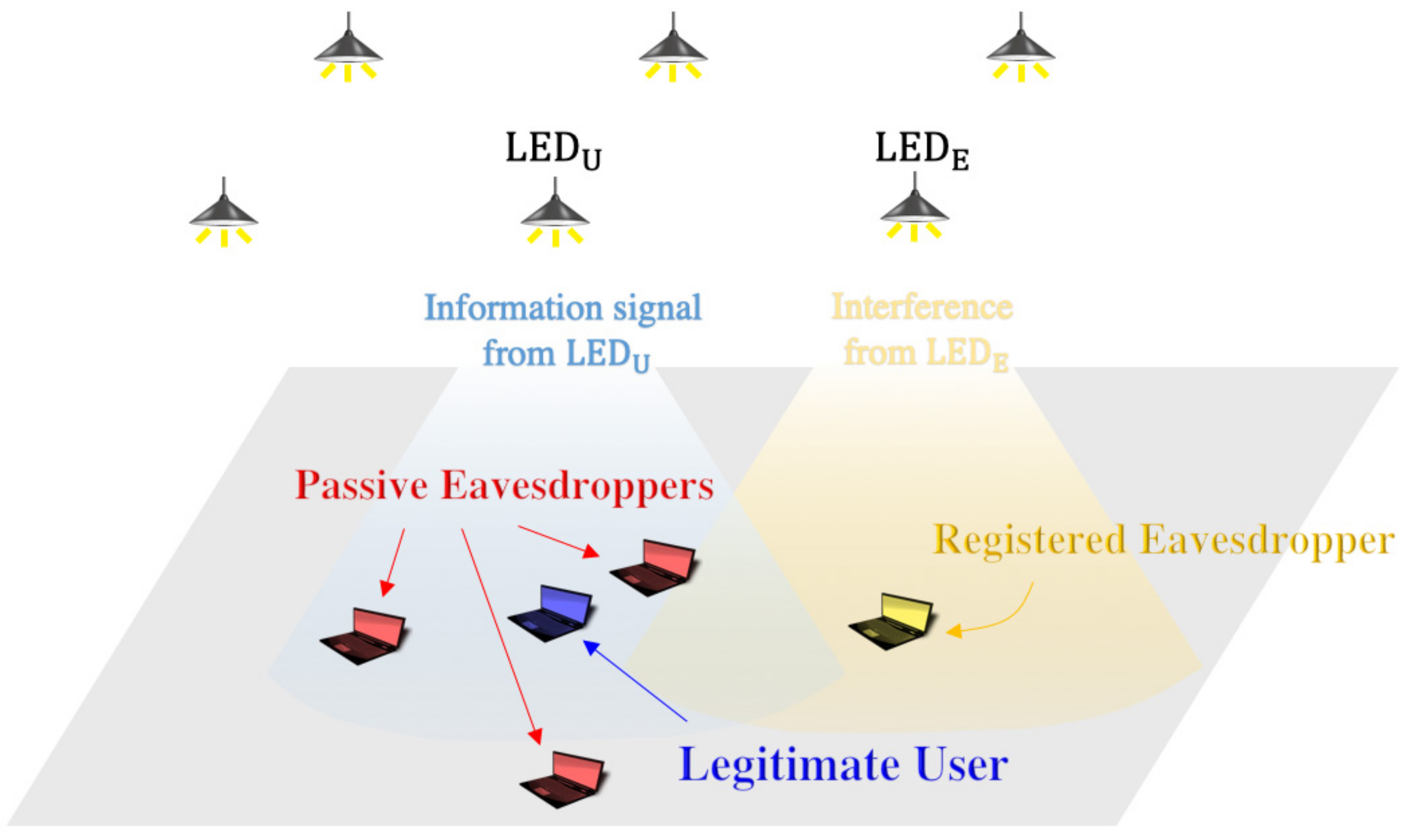
However, in multiuser VLC systems in large open spaces, it would be challenging to distinguish between legitimate and malicious users and would also be impractical to impose on the number and type of eavesdroppers. Moreover, in a public area, it may be too lenient to issue access authority to network users. These properties of multiuser VLC systems lead us to expect an eavesdropping scenario that a malicious user can legitimately access the network and cooperate with other passive (not registered) eavesdroppers to wiretap the information-bearing signal more efficiently. Here, we will look into such a scenario whereby registered and passive eavesdroppers cooperate.
Figure 5 shows an example of the VLC system in question, in which registered and passive eavesdroppers are present. Since the nearest LED is typically assumed to serve the mobile VLC user to maximize the rate of the communication link [10], it is assumed here that LED cooperation does not take place. Thus, registered users, including the legitimate user and the registered eavesdropper, would be served by their nearest LEDs, i.e., LED U and LED E , respectively. Also, a few passive eavesdroppers are assumed to be distributed according to a PPP with density λ E around LED U to wiretap the transmission from LED U to the legitimate user. The registered and passive eavesdroppers can cooperate in the following way. Before and while LED U communicates to the legitimate user employing a wiretap coding scheme, the registered eavesdropper induces its serving transmitter LED E to emit a promised signal. Note that this is possible since the registered eavesdropper has the legitimate right to access the network. The promised signal, which is a waveform modulated from any data bits, e.g., a string of random binary numbers, is already disclosed to other passive eavesdroppers and saved in a remote server/node to be requested by the registered eavesdropper. At the same time, the passive eavesdroppers attempt to wiretap the signal being transmitted from LED U to the legitimate user. Here, since the promised signal, which is supposed to interfere with the signal reception of the desired information, is already known to the passive eavesdroppers, they can cancel the interference to extract only the information component. Note that since the legitimate user does not know the promised signal, the signal coming from LED E can interfere with the communication between LED U and the legitimate user, i.e., it acts like a jamming signal. Therefore, the promised signal can reduce the SINR of the legitimate user while not affecting the passive eavesdroppers.
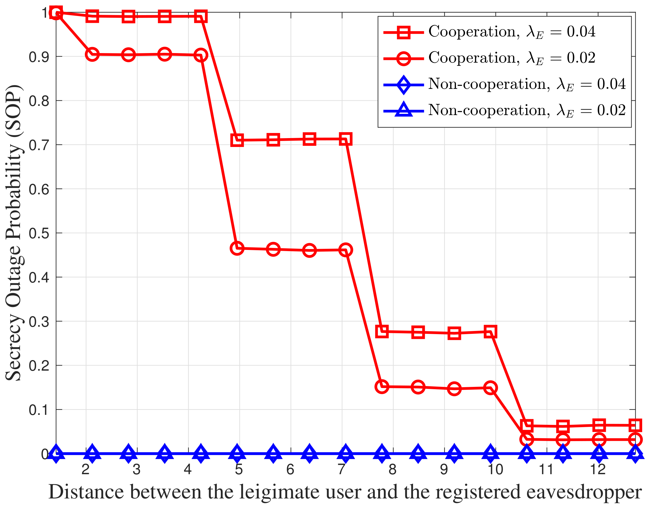
Figure 6 shows the SOP for different passive eavesdropper densities ( λ E ) as a function of the distance between the legitimate user and the registered eavesdropper. Here, the legitimate user is assumed to be located below its serving LED, i.e., LED U . When there is no cooperation among the eavesdroppers, the legitimate user can achieve the highest SINR compared to the eavesdroppers. Thus, as shown in the figure, the SOP without eavesdropper cooperation is zero regardless of λ E . However, when the eavesdroppers cooperate, the promised signal being emitted from LED E interferes with the transmission from LED U to the legitimate user, which results in a decrease of the legitimate user’s SINR; hence, an outage can occur. Moreover, as the registered eavesdropper approaches the legitimate user, its serving LED changes to an LED located closer to the legitimate user, which increases the received power of the promised signal at the legitimate user site; thus, the SOP increases. Note that the LED transmitters are discrete; thus, the SOP with the eavesdroppers’ cooperation shows cascading increases. This result verifies that even when the legitimate user is located at nearest place to its serving LED and is expected to retain the highest SNR among multiple users, the cooperation between registered and passive eavesdroppers can weaken the legitimate user’s reception and effectively wiretap the VLC transmission.

4. Future Directions

We discussed the challenges in securing VLC systems using PLS, explaining that entirely securing VLC transmissions via PLS without knowing the locations and receiver characteristics of passive eavesdroppers may not be guaranteed. Notably, it appears obscure to devise a realistic way to prevent the jamming attack created by the legitimately registered eavesdropper of Section 3.3, except for limiting the number of concurrent users to one. However, this would immensely decrease the spatial efficiency of the VLC systems. Nevertheless, the advantages of PLS that significantly complement the security of higher layers must be exploited in forthcoming VLC systems. Therefore, in what follows, we provide potential (although not perfect) guidelines for improving and designing PLS schemes for VLC systems.
First, for indoor VLC systems, the users’ behaviors and the room layout can be examined with a view to predict the possible (but not exact) locations of the eavesdroppers. For example, considering typical behaviors of office workers in which they mostly work sitting at desks, the probable and approximate locations of the mobile devices are near to the desks rather than in the aisle or the rest area. This anticipation for the locations of eavesdroppers can be mathematically modeled by using tools from stochastic geometry, e.g., inhomogeneous PPP, which can provide additional hints to design and optimize the secrecy metric of PLS schemes in the presence of unknown passive eavesdroppers. For example, ZF precoding in Section 3—A can be improved by considering the statistical locations of the passive eavesdroppers to reduce the SNR in the area that the passive eavesdroppers are highly likely to be located.
Second, to combat the augmented eavesdroppers, jamming is still an advantageous approach since the eavesdroppers, even with powerful receiver architectures, cannot extract the information component from the received signal in the presence of randomized jamming signals. In contrast, jamming signals can be designed such that they lie in the null space of the legitimate user’s channel so as not to disturb information reception. Therefore, improving beyond the traditional jamming strategies, transmitting the information and jamming signals at very closely located LEDs, as discussed in Section 3.2, or randomly choosing the information transmitter and jammers, disregarding the location of the legitimate user, can be possible strategies. The first approach can further improve by forcing both information and jamming signals to be emitted from a single LED by splitting its transmit power into two components. However, this would sacrifice the SINR of the legitimate user. Besides, with the latter approach, i.e., transmitter hopping, the information reception at the legitimate user may be weakened due to the increase of the distances from the information LEDs; thus, appropriate beamforming strategies with multiple LEDs should supplement the signal strength at the legitimate user. In addition, it is also possible to utilize intelligent reflecting surfaces (IRS) for VLC [23] to enhance jamming strategies since eavesdroppers cannot know which element of programmable metasurfaces or mirror arrays of IRS emits the information or jamming signals, respectively.
Third, VLC is viewed as a complementary technology to other RF wireless communication technologies, such as Wi-Fi, mobile networks, mmWave communications, etc., rather than a RF replacement. Hence, both technologies are likely to be combined in a single device to meet the demand for future wireless applications. In this sense, the combination of VLC and RF may significantly enhance secrecy performances by exploiting the inherently different characteristics of RF and VLC channels. More specifically, VLC may promise a very high secrecy capacity when employing an appropriate transmission scheme, while it is entirely subject to a favorable location of a UE concerning an ED. On the other hand, regardless of the receiver locations, RF may not ensure a required secrecy capacity in indoor environments due to shadowing and multipath fading, while it can facilitate uncorrelated transmissions. Utilizing the intrinsically different VLC and RF channels may enable finding an optimal solution that can always provide consumers with an adequate secrecy performance. For example, based on a given communication configuration, it would be possible to make an optimal choice between transmitting a secrecy key by using a keyless PLS scheme of VLC and generating and distributing a secret key by utilizing the distinct channel characteristics of the transmitter’s and UE’s reciprocal RF channel.

5. Conclusions

This article argued that existing physical layer security (PLS) techniques for visible light communication (VLC) systems are still susceptible to various eavesdropping attacks. We showed that, in contrast to radio frequency (RF) systems, the design features of VLC systems and the inherent characteristics of the VLC transceiver components enable the eavesdropper to improve its wiretapping capability and overcome several existing PLS strategies. Furthermore, the presence of active (or registered) and passive eavesdroppers was shown to be a security threat that a VLC system designer must seek to mitigate. To provide secure transmission for the legitimate user, it is necessary to clearly understand and utilize VLC and RF systems’ intrinsic characteristics and improve/develop PLS techniques that can cope with any intelligent attempts that eavesdroppers may make.
Moreover, VLC is viewed as a complementary technology to other RF wireless communication technologies, such as Wi-Fi, mobile networks, mmWave communications, etc., rather than a replacement of others. Hence, both technologies are likely to be synergistically combined in a single device to meet the demand for future wireless applications. In this sense, combining VLC and RF and simultaneously exploiting the inherently different characteristics of RF and VLC channels may significantly enhance secrecy performances.

Author Contributions

Conceptualization, S.C., G.C. and J.P.C.; methodology, S.C., G.C. and J.P.C.; software, S.C., G.C. and J.P.C.; validation, S.C., G.C., J.P.C. and P.X.; formal analysis, S.C. and G.C.; investigation, S.C., G.C. and J.P.C.; writing—original draft preparation, S.C.; writing—review & editing, G.C., J.P.C. and P.X.; supervision, J.P.C. and P.X.; funding acquisition, P.X. All authors have read and agreed to the published version of the manuscript.

Funding

This research received no external funding.

Conflicts of Interest

The authors declare no conflict of interest.

Abbreviations

The following abbreviations are used in this manuscript:
VLCVisible Light Communication
PLSPhysical Layer Security
RFRadio Frequency
WEPWired Equivalent Privacy
WPAWiFi Protected Access
LEDLight Emitting Diode
SISOSingle-Input Single-Output
MISOMultiple-Input Single-Output
CSIChannel State Information
PPPPoisson Point Process
SNRSignal-to-Noise Ratio
SINRSignal-to-Interference-plus-Noise Ratio
SOPSecrecy Outage Probability
FoVField-of-View
ZFZero-Forcing

References

  1. Haas, H.; Yin, L.; Wang, Y.; Chen, C. What is LiFi? J. Light. Technol. 2016, 34, 1533–1544. [Google Scholar] [CrossRef]
  2. Tews, E.; Beck, M. Practical Attacks Against WEP and WPA. In Proceedings of the WiSec ’09—Second ACM Conference on Wireless Network Security, Zurich, Switzerland, 16–18 March 2009; pp. 79–86. [Google Scholar]
  3. Bloch, M.; Barros, J. Physical-Layer Security: From Information Theory to Security Engineering; Cambridge University Press: Cambridge, UK, 2011. [Google Scholar] [CrossRef]
  4. Chen, G.; Coon, J.P.; Di Renzo, M. Secrecy Outage Analysis for Downlink Transmissions in the Presence of Randomly Located Eavesdroppers. IEEE Trans. Inf. Forensics Secur. 2017, 12, 1195–1206. [Google Scholar] [CrossRef] [Green Version]
  5. Tang, J.; Chen, G.; Coon, J.P. Secrecy Performance Analysis of Wireless Communications in the Presence of UAV Jammer and Randomly Located UAV Eavesdroppers. IEEE Trans. Inf. Forensics Secur. 2019, 14, 3026–3041. [Google Scholar] [CrossRef] [Green Version]
  6. Mostafa, A.; Lampe, L. Physical-layer security for indoor visible light communications. In Proceedings of the 2014 IEEE International Conference on Communications (ICC), Sydney, Australia, 10–14 June 2014; pp. 3342–3347. [Google Scholar] [CrossRef]
  7. Mostafa, A.; Lampe, L. Physical-Layer Security for MISO Visible Light Communication Channels. IEEE J. Sel. Areas Commun. 2015, 33, 1806–1818. [Google Scholar] [CrossRef]
  8. Mostafa, A.; Lampe, L. Securing visible light communications via friendly jamming. In Proceedings of the 2014 IEEE Globecom Workshops (GC Wkshps), Austin, TX, USA, 8–12 December 2014; pp. 524–529. [Google Scholar] [CrossRef]
  9. Zaid, H.; Rezki, Z.; Chaaban, A.; Alouini, M.S. Improved achievable secrecy rate of visible light communication with cooperative jamming. In Proceedings of the 2015 IEEE Global Conference on Signal and Information Processing (GlobalSIP), Orlando, FL, USA, 14–16 December 2015; pp. 1165–1169. [Google Scholar] [CrossRef]
  10. Yin, L.; Haas, H. Physical-Layer Security in Multiuser Visible Light Communication Networks. IEEE J. Sel. Areas Commun. 2018, 36, 162–174. [Google Scholar] [CrossRef] [Green Version]
  11. Cho, S.; Chen, G.; Coon, J.P. Enhancement of Physical Layer Security With Simultaneous Beamforming and Jamming for Visible Light Communication Systems. IEEE Trans. Inf. Forensics Secur. 2019, 14, 2633–2648. [Google Scholar] [CrossRef] [Green Version]
  12. Cho, S.; Chen, G.; Coon, J.P. Securing Visible Light Communication Systems by Beamforming in the Presence of Randomly Distributed Eavesdroppers. IEEE Trans. Wirel. Commun. 2018, 17, 2918–2931. [Google Scholar] [CrossRef] [Green Version]
  13. Cho, S.; Chen, G.; Coon, J.P. Zero-Forcing Beamforming for Active and Passive Eavesdropper Mitigation in Visible Light Communication Systems. IEEE Trans. Inf. Forensics Secur. 2021, 16, 1495–1505. [Google Scholar] [CrossRef]
  14. Yesilkaya, A.; Cogalan, T.; Erkucuk, S.; Sadi, Y.; Panayirci, E.; Haas, H.; Poor, H.V. Physical-Layer Security in Visible Light Communications. In Proceedings of the 2020 2nd 6G Wireless Summit (6G SUMMIT), Levi, Finland, 17–20 March 2020; pp. 1–5. [Google Scholar] [CrossRef]
  15. Yang, J.; Kim, I.; Kim, D.I. Optimal Cooperative Jamming for Multiuser Broadcast Channel with Multiple Eavesdroppers. IEEE Trans. Wirel. Commun. 2013, 12, 2840–2852. [Google Scholar] [CrossRef]
  16. Komine, T.; Nakagawa, M. Fundamental analysis for visible-light communication system using LED lights. IEEE Trans. Consum. Electron. 2004, 50, 100–107. [Google Scholar] [CrossRef]
  17. Wang, L.; Yang, N.; Elkashlan, M.; Yeoh, P.L.; Yuan, J. Physical Layer Security of Maximal Ratio Combining in Two-Wave With Diffuse Power Fading Channels. IEEE Trans. Inf. Forensics Secur. 2014, 9, 247–258. [Google Scholar] [CrossRef]
  18. Khisti, A.; Wornell, G.W. Secure Transmission With Multiple Antennas I: The MISOME Wiretap Channel. IEEE Trans. Inf. Theory 2010, 56, 3088–3104. [Google Scholar] [CrossRef] [Green Version]
  19. Marin-Garcia, I.; Guerra, V.; Perez-Jimenez, R. Study and Validation of Eavesdropping Scenarios over a Visible Light Communication Channel. Sensors 2017, 17, 2687. [Google Scholar] [CrossRef] [PubMed] [Green Version]
  20. Cho, S.; Chen, G.; Coon, J.P. Cooperative Beamforming and Jamming for Secure VLC System in the Presence of Active and Passive Eavesdroppers. IEEE Trans. Green Commun. Netw. 2021, 5, 1988–1998. [Google Scholar] [CrossRef]
  21. Pham, T.V.; Pham, A.T. On the secrecy sum-rate of MU-VLC broadcast systems with confidential messages. In Proceedings of the 2016 10th International Symposium on Communication Systems, Networks and Digital Signal Processing (CSNDSP), Prague, Czech Republic, 20–22 July 2016; pp. 1–6. [Google Scholar] [CrossRef]
  22. Arfaoui, M.A.; Ghrayeb, A.; Assi, C.M. Secrecy Performance of Multi-User MISO VLC Broadcast Channels With Confidential Messages. IEEE Trans. Wirel. Commun. 2018, 17, 7789–7800. [Google Scholar] [CrossRef]
  23. Abdelhady, A.M.; Salem, A.K.S.; Amin, O.; Shihada, B.; Alouini, M.S. Visible Light Communications via Intelligent Reflecting Surfaces: Metasurfaces vs Mirror Arrays. IEEE Open J. Commun. Soc. 2021, 2, 1–20. [Google Scholar] [CrossRef]
Figure 1. SNR according to receiver locations when zero-forcing (ZF) precoding is utilized. The 10 × 10 transmitter array consists of LEDs that are uniformly distributed on a square lattice in a room of 20 × 20 m 2 .
Network 02 00004 g001
Figure 2. Secure outage probability (SOP) plotted as a function of distance between legitimate user and active eavesdropper for different densities ( λ E ) of passive eavesdroppers.
Network 02 00004 g002
Figure 3. An example of VLC systems with a jamming strategy, where electron device (ED) is equipped with a narrow field-of-view (FoV) photodiode (PD), oriented directly toward information LED transmitter.
Network 02 00004 g003
Figure 4. SINR according to distance between legitimate user and eavesdropper, who are located at center of room and ( d E , d E ) , respectively. N T LED transmitters are assumed to be uniformly distributed on a square lattice in room of 20 × 20 m 2 . FoV of eavesdropper is denoted by Ψ E . N T = 10 × 10 is used for (a), and Ψ E = 10 is used for (b).
Network 02 00004 g004
Figure 5. An example of a VLC system operating in presence of both registered and passive eavesdroppers.
Network 02 00004 g005
Figure 6. SOP for different densities of passive eavesdroppers ( λ E ) plotted as a function of distance between legitimate user and registered eavesdropper when registered and passive eavesdroppers cooperate. N T = 10 × 10 LED transmitters are assumed to be uniformly distributed on a square lattice in a room of dimension 20 × 20 m 2 .
Network 02 00004 g006
Table 1. Differences in security environments between radio frequency (RF) and visible light communication (VLC) systems.
Channel PropertiesCommunication DevicesPLS Techniques
ReciprocityUncorrelatednessFadingTransmitterReceiverKey-Less
Transmission
Secret Key
Sharing
RFAntennaAntennaFeasibleFeasible
VLC×××LEDPhotodiodeFeasibleInfeasible
Publisher’s Note: MDPI stays neutral with regard to jurisdictional claims in published maps and institutional affiliations.

