Abstract
Transcranial magnetic stimulation (TMS) is a non-invasive neuromodulation technique extensively utilized in neuroscience and clinical medicine; however, its underlying mechanisms require further elucidation. Due to ethical safety considerations, low cost, and physiological similarities to humans, rodent models have become the primary subjects for TMS animal studies. Nevertheless, existing TMS coils designed for rodents face several limitations, including size constraints that complicate coil fabrication, insufficient stimulation intensity, suboptimal focality, and difficulty in adapting coils to practical experimental scenarios. Currently, many studies have attempted to address these issues through various methods, such as adding magnetic nanoparticles, constraining current distribution, and incorporating electric field shielding devices. Integrating the above methods, this study designs a small arc-shaped TMS coil for the frontoparietal region of rats using the inverse boundary element method, which reduces the coil’s interference with experimental observations. Compared with traditional geometrically scaled-down human coil circular and figure-of-eight coils, this coil achieves a 79.78% and 57.14% reduction in half-value volume, respectively, thus significantly improving the focusing of stimulation. Meanwhile, by adding current density constraints while minimizing the impact on the stimulation effect, the minimum wire spacing was increased from 0.39 mm to 1.02 mm, ensuring the feasibility of the coil winding. Finally, coil winding was completed using 0.05 mm × 120 Litz wire with a 3D-printed housing, which proves the practicality of the proposed design method.
1. Introduction
Transcranial Magnetic Stimulation (TMS), as a non-invasive, highly safe, and relatively easy-to-operate neuromodulation technique, has become a research hotspot in the interdisciplinary field of neuroscience and clinical medicine in recent years [1]. Since its initial development by Barker et al. in 1985 [2], the application scope of TMS in both neuroscientific research and clinical therapeutics has continually expanded. Clinically, TMS has demonstrated efficacy in treating a variety of neuropsychiatric disorders, including depression, obsessive–compulsive disorder, and nicotine dependence, as well as neurological conditions such as Parkinson’s disease and post-stroke sequelae [3,4,5,6,7,8].
Although transcranial magnetic stimulation (TMS) demonstrates significant potential in modulating human neural function, its underlying mechanisms require further elucidation through in vivo animal models. Currently, rodent models are predominantly employed in TMS experimental studies [9,10], primarily due to their numerous advantageous attributes. Rodents are small in size, low in rearing cost, and space-efficient. Moreover, they have short reproductive cycles and high fecundity, allowing them to provide a large number of experimental samples in a short time, thus significantly reducing experimental costs [11,12]. Furthermore, the nervous systems of rodents are highly similar to those of humans at many key levels, and their brain structures and neural conduction mechanisms can simulate the basic functions of the human brain to a certain extent, providing an ideal model for studying the stimulating effect of TMS on the brain and neural regulatory mechanisms [13,14]. Rats have a docile temperament and are easy to grasp and manipulate, which reduces operational errors in experiments and improves the stability and reproducibility of the experiments.
However, in the actual process of conducting experiments on rodents, there are also many difficulties, the most significant of which is the lack of special TMS coils designed specifically for rodents. The size and shape of the rodent brain differ drastically from those of the human brain. Taking rats as an example, the complexity of folds in their brains is far less than that in humans, and their brains are extremely small. This makes conventional commercial TMS coils for the human brain incompatible with the unique morphology of the rat brain. Since the coil size is much larger than the rat brain, it tends to stimulate many non-target brain regions, even producing a whole-brain stimulation effect. With poor focusing performance, such coils cannot be used to study the impact of stimulating different brain regions on rats. Additionally, the small size of the rat brain results in limited space for wire winding. This means that when some high-focused human-brain TMS coils are scaled down proportionally, certain regions have dense wires with excessively small spacing, making actual winding practically impossible.
The proportional miniaturization of commercial human brain TMS coils results in increased conductor density, which exacerbates issues of wire congestion and causes a significant decline in coil focality and stimulation intensity [15,16]. The incorporation of electromagnetic shielding plates effectively enhances the coil’s focality; however, this approach also markedly reduces the generated electric field strength [17]. TMS coils designed through the integration of multiple circular coil elements, due to their increased number, generate higher heat, limiting their capacity for prolonged operation [18,19]. To address the heating issue, one approach is to design a cooling system for the coil, which enables the coil to generate a relatively high electric field intensity and operate for an extended period; however, the focusing effect of the electric field it produces is insufficient [20]. In addition to coil winding methods, there are approaches to improve coil performance by researching coil materials. For example, Mn-Zn ferrite materials are incorporated into the coil [21], or silicon steel sheets are added to circular coils [22], both aiming to enhance the focusing capability of the coil. Furthermore, there are some studies that have employed the method of magnetic nanoparticles to make the stimulation more gentle [23].
The aforementioned approaches primarily involve iterative modifications to existing coil structures based on stimulation efficacy, representing a forward design methodology. In contrast, the recently proposed inverse boundary element method (IBEM)-based inverse TMS coil design method is fundamentally different. This approach enables the inverse calculation of coil geometry from a specified target electric field distribution, such as the desired cortical stimulation pattern at a brain target site. The existing literature has employed this methodology to design planar, spherical, and irregular helmet-shaped TMS coils for human applications [24,25,26,27], as well as a closed cylindrical coil for rodent models [28]. However, practical experimental procedures often necessitate methods to observe animal responses, such as direct visual inspection or optical fiber photometry systems [29]. The closed cylindrical coil design cannot accommodate these observational requirements, and compared to traditional figure-eight coils, the cylindrical coil presents challenges in accurately positioning and immobilizing the animal during stimulation experiments.
In summary, the design of a compact TMS coil for rodent models faces several key challenges:
- Limited space leads to difficulties in coil winding;
- The stimulation area of the coil is large, and the focusing ability is insufficient;
- The coil is difficult to use in actual experiments.
In response to the above problems, this paper adopts an inverse TMS coil design method based on the inverse boundary element method and designs an arc-shaped coil in an arc-shaped area above the rat’s brain. On the premise of ensuring experimental observation conditions, it improves the intensity and focality of the stimulation electric field. Meanwhile, to avoid excessively dense wires, it limits the wire spacing by adding current density constraints to the current surface [30], thus ensuring the feasibility of coil winding.
The structure of this paper is as follows: firstly, we present the derivation of the stream function calculation formula based on the inverse boundary element method, along with the regulatory mechanism of current density constraints on coil spacing; secondly, we outline the design of a targeted stimulation coil for the rat’s frontoparietal cortex; thirdly, we perform a comparative analysis of three coil configurations: a scaled-down circular coil and figure-eight coil based on proportional reduction in the forward design and a TMS coil designed via inverse boundary element method, with simulation measurements of their stimulation efficacy to validate the feasibility of the design approach; additionally, we make a comparison of coils before and after the implementation of current density constraints to verify their effectiveness in limiting coil spacing; finally, we present the fabrication of coil housings using 3D printing and the winding of the coils with 1mm diameter excitation wire.
2. Design Theory
2.1. Inverse Boundary Element Method Based on Stream Function
The concept of the stream function originates from fluid dynamics. In a two-dimensional flow field, due to the incompressibility of planar potential flow, the divergence of its two-dimensional streamlines must be zero to satisfy continuity. Similarly, based on the principle of current continuity, the current density J distributed over the surface of a coil must also adhere to a divergence-free condition, expressed as:
For the two-dimensional plane, assuming a scalar potential , the general solution of Equation (1) can be expressed as:
Among them, represents the stream function. If the plane is discretized into triangular elements composed of multiple vertices and triangles, as illustrated in Figure 1, the surface current density vector for each discretized triangular element can be expressed in terms of the stream functions at its three vertices,
where represents the stream function value at each node of the discretized plane, denotes the corresponding directional vector, and N signifies the total number of discrete nodes on the plane. For example, in the case of a discrete triangle, the current density of each triangle is obtained by adding the values of the stream function at the three vertices and multiplying them by the counterclockwise basis vector of the corresponding edge. This approach enables the calculation of the current density for all discrete triangles, thereby allowing the determination of the vector magnetic potential at any arbitrary point within the space.
where R is any point in the space, S represents a certain discrete triangle, and r is any point within the discrete triangle. Combining Equations (3) and (4), we can obtain
where is a constant calculated by the formula. Without considering electrical conductivity, according to the relationship between the electric field and the magnetic vector in space, it is:
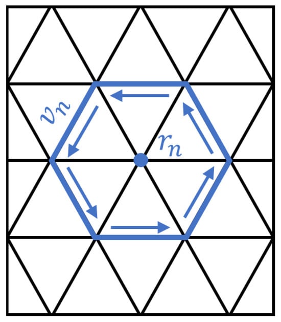
Figure 1.
A schematic diagram of a discretized current distribution over a planar triangular mesh, illustrating a specific node and the associated current flow vector within the relevant triangular element.
Generally, the stimulation current is a sine wave, so it can be derived
where is the frequency of the stimulation current. Therefore, from Equations (6) and (7), we can obtain:
Based on the aforementioned formula, once the discrete plane current and the discrete point distribution required for electric field computation are established, the calculation matrix for predicting the electric field via the stream function can be derived, serving as the basis for subsequent optimization analyses.
The primary properties of the stream function are as follows:
- The streamlines (where C is a constant) are parallel to the current density vector of the current surface;
- The sequential arrangement of equipotential lines according to a certain interval represents the winding pattern of the coil, and the current along the streamlines is constant.
Consequently, in the design process of TMS coils, solving the stream function and analyzing its equipotential lines enables efficient determination of the specific winding configuration. By interpolating between equipotential lines of the stream function, we get the difference between the contour lines,
where denotes the stream function of the discrete plane, and r corresponds to each stream function node. represents the number of coil turns to be wound, as illustrated in Figure 2. The winding trajectory of each coil turn is derived from the equipotential lines. Subsequently, it is necessary to select the convergence points of the wires and manually connect each turn to form a complete coil consisting of a single continuous wire.
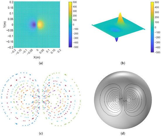
Figure 2.
The coil winding process designed via the stream function: (a) Optimize stream function distribution of discrete nodes. (b) The stream function at any point on the current-carrying surface is obtained through interpolation calculation. (c) Calculate equipotential points of the stream function. (d) Connect the equipotential points in sequence to obtain the winding pattern of the coil.
2.2. Constrained Design
The most important constraints for coils include constraints on electric field distribution and different objective functions selected for various application scenarios, such as minimum energy, minimum resistance, and minimum inductance. Taking the minimum coil energy as an example, the calculation method of coil energy is derived as follows.
The energy of a coil is stored as magnetic field energy, and its energy U is calculated as:
where S represents a certain discrete triangle, r is any point within the discrete triangle, and can be calculated using Equation (4). Each current node can be regarded as a counterclockwise circular current. When the stream function is determined, the current density of each small triangle is constant. Therefore, combined with Equation (4), it is only necessary to integrate over each pair of triangles. For identical triangles, the undefined case of may occur, which can be calculated using methods described in [24]. For different triangles, Gaussian integration can be used to calculate the energy between each pair of small triangles:
where i and j are any two nodes on the discrete current surface; and are sets of small triangles containing nodes i and j, respectively; and are triangles in and , respectively; and and are arbitrary points in and , respectively. After calculating the energy between any two small triangles, the total energy of the coil is expressed in quadratic form:
where
In addition to the objective function, another constraint to be set is the target electric field distribution. The electric field is a vector, and its direction must be considered in addition to its magnitude. However, since the interior point method [31] for optimizing TMS coils can only use linear constraints, multi-directional linear calculations are used to replace the calculation of the electric field magnitude, as shown in Figure 3. The components of the polyhedron in the direction of each vertex are calculated; if all directions are smaller than a certain value, the magnitude of the electric field can be considered smaller than that value. Considering the computational load of constraint conditions, an excessive number of faces on the polyhedron will lead to an excessively large number of constraints required for optimization, resulting in issues such as insufficient operation speed and memory capacity. After testing polyhedrons with different numbers of faces, a polyhedron with 320 faces was selected, and component calculations were performed in 162 directions. This resulted in a maximum error of only 1.7713%, which falls within the acceptable range.

Figure 3.
Linear constraints replacing norm constraints: (a) A 20-faced polyhedron with 12 vertices, maximum error = 20.5215%. (b) An 80-faced polyhedron with 42 vertices, maximum error = 6.5738%. (c) A 320-faced polyhedron with 162 vertices, maximum error = 1.7713%.
In addition to electric field distribution constraints, other design constraints can be added. For example, to limit the wire spacing of the coil, current density constraints can be introduced. According to the characteristics of the stream function, its equipotential lines correspond to the coil winding pattern; thus, constraining the wire spacing is equivalent to constraining the current density within a specific range. Based on the derivation of the stream function calculation formula in Section 2.1, each discrete triangle on the current-carrying surface has a surface current density. Constraining the surface current density of the triangles can achieve the effect of constraining wire spacing.
Like the electric field, surface current density is a vector and must be converted into linear constraints for solution. Unlike the electric field, it lies within the plane where the triangular surface is located and can be transformed into a 2D vector within that plane. As shown in the Figure 4, the projection of a vector in any direction onto several directions can be calculated. Taking 8 directions as an example, the minimum error is . The errors for different numbers of directional vectors are shown in the following figure. Considering limited computational capacity—where N directions require adding N constraints, and a large number would slow down calculations—a total of 24 directions are selected, with a maximum error of 0.8555%, approximating the nonlinear calculation of magnitude.
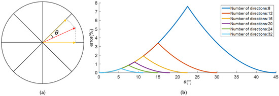
Figure 4.
Planar linear constraints replacing norm constraints: (a) The red arrow represents a vector in any planar direction, and the two orange arrows represent projections onto the two nearest directions, with a minimum error of . (b) Relationship between error and angle for different numbers of directions.
During optimization, it is not necessary to constrain the surface current density of all discrete triangles. Instead, a threshold k is set, after each solution, surface current density constraints are added to triangles with surface current density greater than k until the surface current density of all discrete triangles is less than k.
Once the objective function, electric field distribution constraints, and surface current density constraints are determined, a linear programming problem is formulated, whose mathematical expression is as follows:
where 100 V/m represents the threshold required for a normal organism to receive a stimulus, while 50 V/m refers to half of the maximum threshold, corresponding to the subsequent half-volume.
3. Design and Simulation Outcomes
The coil path was generated by inversely optimizing the stream function distribution in MATLAB R2023a. First, the coordinates of equipotential lines were calculated and exported to an Excel spreadsheet. Subsequently, the 3D coordinates of each equipotential line were imported into COMSOL 6.0 via a script, with the geometric type set to a closed interpolating function and all units uniformly standardized to meters. Instead of being modeled as a solid entity, the coil was approximated using edge currents. This treatment was based on the 0.05 mm × 120 Litz wire used in actual winding, its thin diameter and stranded structure allow the skin effect to be neglected, which meets the application conditions for edge current simulation. The rat model was derived from whole-body computed tomography data in Reference [32]. The simulation domain was defined as a spherical air domain with a radius of 0.3 m, a size much larger than the geometric dimensions of the rat. Only the coil and the rat were included in the domain, no ground or reference conditions were set, nor were infinite elements or scattering boundaries employed. For the model’s physical field, the Magnetic Field (mf) module in COMSOL was selected. Notably, neither the theoretical derivation in this paper nor the COMSOL model considered tissue electrical conductivity; instead, rat tissues were treated as geometric boundaries and equivalent to free space for modeling. The core purpose of this setup was to eliminate interference from complex parameters such as tissue electrical conductivity, and to focus on verifying the electric field focusing advantage of the coil designed via the IBEM over traditional coils under unified conditions, thereby more clearly highlighting the inherent superiority of the proposed design method.
3.1. Arc-Shaped Circular TMS Coil
The arc-shaped circular coil is designed based on the commercial Halo coil for the human body, as shown in Figure 5. A similar coil was also designed in Reference [20], with a cooling system added, and actual experiments were conducted on rats. The small Halo coil used in this paper consists of 16 circular rings. 16 concentric circles with radii ranging from 5 mm to 20 mm are designed at intervals of 1 mm. The projection of these circles onto a cylinder with a radius of 25 mm directly below them forms the arc-shaped circular coil.
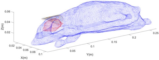
Figure 5.
Schematic diagram of the position of the forward-designed arc-shaped circular coil, where blue represents the rat’s skin surface model, red represents the rat’s brain surface model, and colored rings represent the coil contours.
3.2. Arc-Shaped Figure-Eight TMS Coil
The arc-shaped figure-eight coil is designed based on the commercially available human figure-eight coil. It consists of two groups of 7 concentric circular coils, with radii ranging from 6 mm to 12 mm, respectively, totaling 14 turns. The size of this 8-shaped coil structure and the number of coil layers are roughly the same as those of the reverse-designed coil. We strive to keep the sizes of the coils designed by the two methods as similar as possible, as shown in Figure 6.
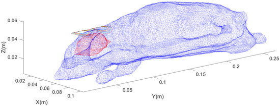
Figure 6.
Schematic diagram of the position of the forward-designed arc-shaped figure-eight coil, where blue represents the rat’s skin surface model, red represents the rat’s brain surface model, and colored rings represent the coil contours.
3.3. TMS Coil Designed by Inverse Boundary Element Method
For the coil designed by the inverse boundary element method, a cylindrical surface with a radius of 25 mm, a length of 50 mm, and an angle of 120° was selected as the current-carrying surface. This surface was divided into discrete triangles, with a total of 1160 nodes and 2184 triangular meshes. The relative position between the coil and the rat is shown in Figure 7.
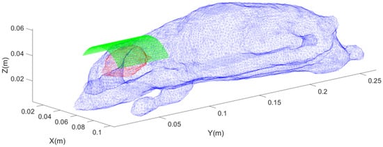
Figure 7.
Schematic diagram of the position of the inversely designed coil, where blue represents the rat’s skin model, red represents the rat’s brain surface model, and green represents the distribution of discrete triangular elements on the current-carrying surface.
3.4. Simulation Results of the Arc-Shaped Circular TMS Coil
The shape of the forward-designed arc-shaped circular coil is shown in Figure 8a. A sinusoidal stimulation current with an amplitude of 6 kA and a frequency of 1 kHz was applied, and the electric field intensity distribution on the rat brain surface is presented in Figure 8b. The peak value can reach 103.58 V/m, and the calculated half-value volume (the volume within the rat brain where the electric field intensity is half of the maximum electric field intensity on the surface) is 1.78 cm3. It can be clearly observed from the simulation results that within the region around the frontal and parietal lobes of the rat brain, the intensity of the stimulation electric field is relatively high, exceeding the neural stimulation threshold of the rat. The activated brain region is large, indicating a poor focusing effect of the stimulation.
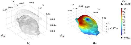
Figure 8.
The forward-designed arc-shaped circular coil: (a) The contour of the arc-shaped circular coil and its relative position to the rat. (b) Presents the electric field distribution on the surface of the rat brain when a sinusoidal current with an amplitude of 6 kA and a frequency of 1 kHz is applied as the stimulation current.
3.5. Simulation Results of the Arc-Shaped Figure-Eight TMS Coil
The shape of the forward-designed arc-shaped figure-eight coil is shown in Figure 9a. A sinusoidal stimulation current with an amplitude of 5 kA and a frequency of 2 kHz was applied, and the electric field intensity distribution on the rat brain surface is presented in Figure 9b. The peak value can reach 100.85 V/m, and the calculated half-value volume is 0.84 cm3.
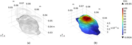
Figure 9.
The forward-designed arc-shaped figure-eight coil: (a) The contour of the arc-shaped figure-eight coil and its relative position to the rat. (b) Presents the electric field distribution on the surface of the rat brain when a sinusoidal current with an amplitude of 5 kA and a frequency of 2 kHz is applied as the stimulation current.
It can be clearly observed from the simulation results that compared with the forward-designed arc-shaped circular coil, the stimulation area of this coil is significantly reduced, and the focusing degree is remarkably improved. In terms of stimulating data, although the current required to achieve the stimulation electric field is slightly increased, the half-value volume is significantly reduced, accounting for only 47.19% of that of the circular coil, indicating a substantial improvement in focusing performance.
3.6. Simulation Results of the TMS Coil Designed by the Inverse Boundary Element Method
The frontoparietal region of the rat brain was selected as the stimulation area, and an arc-shaped coil was designed. Its winding pattern is shown in Figure 10a, and the equipotential lines of the stream function form a set of closed curves in space, and connecting the adjacent closed curves at the wire convergence points constitutes the actual winding trajectory. The coil path was imported into COMSOL for simulation verification. A sinusoidal current with an amplitude of 6 kA and a frequency of 2 kHz was applied, and the electric field distribution is presented in Figure 10b. The peak electric field intensity on the rat brain surface reaches 98.26 V/m, and the calculated half-value volume is 0.36 cm3.
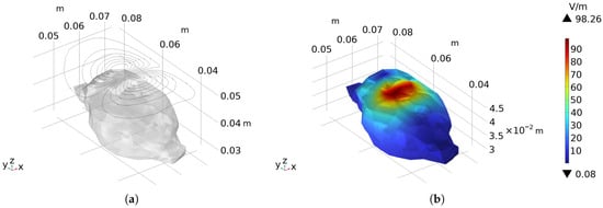
Figure 10.
The coil reversely designed by the inverse boundary element method: (a) The winding pattern of the coil and its relative position to the rat’s brain. (b) Presents the electric field distribution on the surface of the rat brain when a sinusoidal current with an amplitude of 6 kA and a frequency of 2 kHz is applied as the stimulation current.
As observed from the electric field intensity distribution map on the rat brain surface, the stimulation region is concentrated in the frontoparietal area. Compared with the arc-shaped figure-eight coil with relatively high focusing performance, this coil exhibits a smaller stimulation region and a higher focusing degree. The half-value volume is reduced by 79.78% compared with the arc-shaped circular coil and by 57.14% compared with the arc-shaped figure-eight coil. These results demonstrate that the coil designed by the inverse method achieves a significant improvement in stimulation focusing compared with the forward-designed coils.
3.7. Adding Current Density Constraints
As can be seen from Figure 10, the coil spacing at the central convergence area is small, with the measured minimum spacing being only 0.39 mm. If a wire with a diameter of 1 mm is planned to be used, this coil pattern cannot actually be wound. The current density distribution map of the wire layout is plotted as shown in the following Figure 11a, with the maximum current density reaching 8.68 kA/mm, and the current density is relatively high at the center, resulting in dense coil distribution.
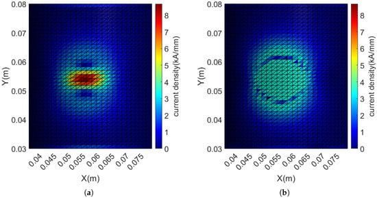
Figure 11.
Distribution of current density before and after adding current density constraints: (a) Without current density constraints, the maximum current density is 8.68 kA/mm. (b) After adding current density constraints, all current densities are constrained to be less than 3.5 kA/mm (with an error within 5%).
According to the constraints on the current density of discrete triangular elements described in Section 2.2, a current density of 3.5 kA/mm is set as the threshold. This threshold was determined through manual optimization to ensure that the wire spacing met the requirements. All discrete triangular elements with current density exceeding this threshold are constrained. After optimization calculation, new discrete triangular elements exceeding the threshold are continuously added to the constraints until the amount of current density exceeding the threshold is no more than 5% in all cases. Through iterative optimization, 176 current density constraints are gradually added, and the resulting current density distribution is shown in the following Figure 11b. The corresponding coil winding pattern is shown in Figure 12a, with the coil spacing significantly increased. The measured minimum spacing is increased to 1.02 mm, which can meet the requirement of winding with a 1 mm diameter wire.
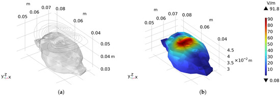
Figure 12.
The coil designed with the addition of current density constraints: (a) The winding pattern of the coil and its relative position to the rat’s brain. (b) Presents the electric field distribution on the surface of the rat brain when a sinusoidal stimulation current with an amplitude of 6 kA and a frequency of 2 kHz is applied.
Import the coil into COMSOL for simulation to verify its stimulation effect, as shown in the Figure 12b. With a sinusoidal current of 6 kA amplitude and 2 kHz frequency applied, the peak electric field intensity on the rat’s brain surface reaches 91.80 V/m, and the calculated half-value volume is 0.40 cm3. Compared with the case without current density constraints, the peak electric field intensity only decreases by 6.6%, and the half-value volume increases by 11.1%. Both the peak electric field intensity and focusing degree decrease slightly, but the minimum wire spacing increases by 161.54% and is constrained within 1 mm, enabling winding with a 1 mm wire. Compared with the arc-shaped circular coil, the half-value volume is reduced by 77.53%, and compared with the arc-shaped figure-eight coil, it is reduced by 52.38%. These results demonstrate that adding current density constraints can effectively limit the spacing of the conductors, ensuring the wrappability of the coil.
To date, the design and simulation of the four coil types have been completed, and the parameters related to their stimulation modes and stimulation effects are presented in the Table 1.

Table 1.
Comparison of stimulation parameters and stimulation effects among different coils.
3.8. Coil Winding
The optimized coil modeling is shown in Figure 13a. The shell is fabricated using 3D printing with photosensitive resin as the material, and the wire used is a 0.05 mm × 120 Litz wire. The physical image of the wound coil is shown in the following Figure 13b. Meanwhile, after the winding is completed, the parameters of the coil are measured, with a resistance of 0.126 and an inductance of 4.32 .
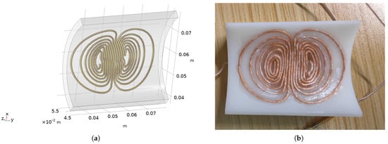
Figure 13.
IMAGES of coil winding: (a) Optimized coil modeling. (b) The coil wound after 3D printing.
4. Conclusions and Discussion
In this study, a small cylindrical TMS coil was designed using an inverse TMS coil design method based on the inverse boundary element method. With the frontoparietal brain region of rats as the stimulation target and the minimum coil energy as the objective function, the designed coil achieved a half-value volume of only 0.36 cm3. Compared with the forward-designed arc-shaped circular coil and arc-shaped figure-eight coil, its half-value volume was reduced by 79.78% and 57.14%, respectively, indicating a significant improvement in stimulation focusing. Meanwhile, by adding current density constraints to discrete triangular elements, the current density within a specific area was restricted, and the gradient of the stream function was limited. This increased the wire spacing from 0.39 mm to 1.02 mm (an improvement of 161.54%), exceeding 1 mm, which ensured the feasibility of coil winding. Finally, based on the designed coil model, 3D printing was carried out, and then the coil was wound using 0.05 mm × 120 Litz wire.
Based on the current design and simulation results, the experimental rat TMS coil designed using the inverse boundary element method achieves a good balance between focusing performance and wire winding feasibility, but there is still room for optimization and expansion. The inverse boundary element method significantly reduces the stimulation half-value volume by inferring the coil structure from the target electric field, providing the possibility of precise stimulation. However, the current stimulation area is concentrated in a single region of the frontal–parietal lobe. In the future, it can explore multi-region coordinated stimulation, matching the discrete current surface with different functional areas of the rat brain, and combining the flow function constraints to achieve precise control of neural circuits. Compared with specialized coils for other rodents, the coil with ferrite core can enhance the magnetic field and reduce leakage, but it increases volume and weight and is prone to nonlinear deviations in the magnetic field. This design without a core is lighter and has better magnetic field linearity, and it can attempt a “current surface + local core” mixed structure to enhance the magnetic field strength. The coil with a cooling system extends the stimulation duration but increases complexity. This design is feasible for short-term heat dissipation, and long-term heat dissipation channels can be reserved for optimization. In terms of process, manual wire winding is prone to deviation. In the future, precise mechanical winding or laser selective melting can be used to directly form the metal coil. After the prototype is prepared, magnetic field distribution measurement needs to be carried out, and a high-precision measurement system should be built to compare the measured and simulated data. Combined with behavioral and electrophysiological experiments, the stimulation effect can be verified. In addition, the inverse boundary element method can be designed based on any curved surface, providing a possibility for cross-species coil development. Integrated with optical recording equipment, it can also achieve “stimulation–recording” integration, further enhancing its application value in neuroscientific research.
Author Contributions
Conceptualization, C.Z. and Y.X.; Methodology, C.Z. and Y.X.; Software, C.Z. and L.J.; Validation, C.Z., L.H. and P.Y.; Formal analysis, C.Z.; Investigation, C.Z., L.J., L.H. and H.L.; Resources, L.J., H.L. and P.Y.; Data curation, L.H., H.L. and P.Y.; Writing—original draft, L.J.; Writing—review & editing, C.Z., Y.X. and L.J.; Visualization, H.L.; Supervision, Y.X.; Project administration, Y.X.; Funding acquisition, Y.X. All authors have read and agreed to the published version of the manuscript.
Funding
This research was funded by the 2025 UNSW—HUST Global Research & Impact Program (GRIP).
Data Availability Statement
The original contributions presented in this study are included in the article. Further inquiries can be directed to the corresponding author.
Conflicts of Interest
The authors declare no conflicts of interest.
References
- Cortes, R.A.; Holzman, D.D.; Green, A.E. Neuromodulation to Enhance Creative Cognition: A Review of New and Emerging Approaches. J. Cogn. Enhanc. 2023, 7, 18. [Google Scholar] [CrossRef]
- Barker, A.T.; Jalinous, R.I.; Freeston, I.L. Non-invasive magnetic stimulation of human motor cortex. Lancet 1985, 325, 1106–1107. [Google Scholar] [CrossRef]
- O’Reardon, J.; Solvason, H.; Janicak, P.; Sampson, S.; Isenberg, K.; Nahas, Z.; Mcdonald, W.W.; Avery, D.; Fitzgerald, P.; Loo, C. Efficacy and Safety of Transcranial Magnetic Stimulation in the Acute Treatment of Major Depression: A Multisite Randomized Controlled Trial. Biol. Psychiatry 2007, 62, 1208–1216. [Google Scholar] [CrossRef] [PubMed]
- George, M.S.; Lisanby, S.H.; Avery, D.; McDonald, W.M.; Durkalski, V.; Pavlicova, M.; Anderson, B.; Nahas, Z.; Bulow, P.; Zarkowski, P.; et al. Daily left prefrontal transcranial magnetic stimulation therapy for major depressive disorder: A sham-controlled randomized trial. Arch. Gen. Psychiatry 2010, 67, 507–516. [Google Scholar] [CrossRef] [PubMed]
- Carmi, L.; Tendler, A.; Bystritsky, A.; Hollander, E.; Blumberger, D.M.; Daskalakis, Z.; Ward, H.; Lapidus, K.; Goodman, W.; Casuto, L.; et al. Efficacy and Safety of Deep Transcranial Magnetic Stimulation for Obsessive-Compulsive Disorder: A Prospective Multicenter Randomized Double-Blind Placebo-Controlled Trial. Am. J. Psychiatry 2019, 176, 931–938. [Google Scholar] [CrossRef] [PubMed]
- Zangen, A.; Moshe, H.; Martinez, D.; Barnea-Ygael, N.; Vapnik, T.; Bystritsky, A.; Duffy, W.; Toder, D.; Casuto, L.; Grosz, M.L.; et al. Repetitive transcranial magnetic stimulation for smoking cessation: A pivotal multicenter double-blind randomized controlled trial. World Psychiatry 2021, 20, 397–404. [Google Scholar] [CrossRef]
- George, M.S.; Lisanby, S.H.; Sackeim, H.A. Transcranial magnetic stimulation: Applications in neuropsychiatry. Arch. Gen. Psychiatry 1999, 56, 300–311. [Google Scholar] [CrossRef]
- Strafella, A.P.; Paus, T. Modulation of cortical excitability during the implicit learning of a sensorimotor task. Neuroreport 2000, 11, 3555–3559. [Google Scholar]
- Uzair, M.; Abualait, T.; Arshad, M.; Yoo, W.K.; Mir, A.; Bunyan, R.F.; Bashir, S. Transcranial magnetic stimulation in animal models of neurodegeneration. Neural Regen. Res. 2022, 17, 251–265. [Google Scholar] [CrossRef]
- Boonzaier, J.; Petrov, P.I.; Otte, W.M.; Smirnov, N.; Neggers, S.F.W.; Dijkhuizen, R.M. Design and Evaluation of a Rodent-Specific Transcranial Magnetic Stimulation Coil: An In Silico and In Vivo Validation Study. Neuromodulation 2020, 23, 324–334. [Google Scholar] [CrossRef]
- Neziri, S.; Köseoğlu, A.E.; Deniz Köseoğlu, G.; Özgültekin, B.; Özgentürk, N. Animal models in neuroscience with alternative approaches: Evolutionary, biomedical, and ethical perspectives. Anim. Models Exp. Med. 2024, 7, 868–880. [Google Scholar] [CrossRef]
- Rinwa, P.; Eriksson, M.; Cotgreave, I.; Bäckberg, M. 3R-Refinement principles: Elevating rodent well-being and research quality. Lab. Anim. Res. 2024, 40, 11. [Google Scholar] [CrossRef] [PubMed]
- Beauchamp, A.; Yee, Y.; Darwin, B.C.; Raznahan, A.; Mars, R.B.; Lerch, J.P. Whole-brain comparison of rodent and human brains using spatial transcriptomics. eLife 2022, 11, e79418. [Google Scholar] [CrossRef]
- Wong, H.H.W.; Chou, C.Y.C.; Watt, A.J.; Sjöström, P.J. Neural Circuits: Comparing mouse and human brains. eLife 2023, 12, e90017. [Google Scholar] [CrossRef] [PubMed]
- Rotenberg, A.; Muller, P.A.; Vahabzadeh-Hagh, A.M.; Navarro, X.; López-Vales, R.; Pascual-Leone, A.; Jensen, F. Lateralization of forelimb motor evoked potentials by transcranial magnetic stimulation in rats. Clin. Neurophysiol. 2010, 121, 104–108. [Google Scholar] [CrossRef]
- Rastogi, P.; Hadimani, R.L.; Jiles, D.C. Investigation of Coil Designs for Transcranial Magnetic Stimulation on Mice. IEEE Trans. Magn. 2016, 52, 5200404. [Google Scholar] [CrossRef]
- Gasca, F.; Richter, L.; Schweikard, A. Simulation of a conductive shield plate for the focalization of transcranial magnetic stimulation in the rat. In Proceedings of the 2010 Annual International Conference of the IEEE Engineering in Medicine and Biology, Buenos Aires, Argentina, 31 August–4 September 2010; pp. 1593–1596. [Google Scholar]
- March, S.D.; Stark, S.J.; Hadimani, R.L.; Stiner, D.R.; Senter, M.J.; Spoth, K.K.; Crowther, L.J.; Jiles, D.C. Thermal and Mechanical Analysis of Novel Transcranial Magnetic Stimulation Coil for Mice. IEEE Trans. Magn. 2014, 50, 5100805. [Google Scholar] [CrossRef]
- Tang, A.D.; Lowe, A.S.; Garrett, A.R.; Woodward, R.; Bennett, W.; Canty, A.J.; Garry, M.I.; Hinder, M.R.; Summers, J.J.; Gersner, R.; et al. Construction and evaluation of rodent-specific TMS coils. Front. Neural Circuits 2016, 10, 47. [Google Scholar] [CrossRef]
- Parthoens, J.; Verhaeghe, J.; Servaes, S.; Miranda, A.; Stroobants, S.; Staelens, S. Performance Characterization of an actively cooled repetitive transcranial magnetic stimulation coil for the rat. Neuromodulation 2016, 19, 459–468. [Google Scholar] [CrossRef] [PubMed]
- Jayaprakash, S.; Priyam, R.; Prabhu, G.N.; Hadimani, R.L.; Mani, M. Transcranial Magnetic Stimulation: Design of a Stimulator and a Focused Coil for the Application of Small Animals. IEEE Trans. Magn. 2018, 54, 5200405. [Google Scholar] [CrossRef]
- Meng, Q.; Jing, L.; Badjo, J.P.; Du, X.; Hong, E.; Yang, Y.; Lu, H.; Choa, F.S. A novel transcranial magnetic stimulator for focal stimulation of rodent brain. Brain Stimul. 2018, 11, 663–665. [Google Scholar] [CrossRef]
- Odutola, T.; Myrovali, E.; Makridis, A.; Maniotis, N.; Angelakeris, M.; Kimiskidis, V.; Samaras, T. Can magnetic nanoparticles thermally assist the beneficiary role of transcranial magnetic stimulation? In Proceedings of the 2018 EMF-Med 1st World Conference on Biomedical Applications of Electromagnetic Fields (EMF-Med), Split, Croatia, 10–13 September 2018; pp. 1–2. [Google Scholar]
- Koponen, L.M.; Nieminen, J.O.; Ilmoniemi, R.J. Minimum-energy coils for transcranial magnetic stimulation: Application to focal stimulation. Brain Stimul. 2015, 8, 124–134. [Google Scholar] [CrossRef]
- Koponen, L.M.; Nieminen, J.O.; Mutanen, T.P.; Stenroos, M.; Ilmoniemi, R.J. Coil optimisation for transcranial magnetic stimulation in realistic head geometry. Brain Stimul. 2017, 10, 795–805. [Google Scholar] [CrossRef]
- Koponen, L.M.; Nieminen, J.O.; Ilmoniemi, R.J. Multi-locus transcranial magnetic stimulation—Theory and implementation. Brain Stimul. 2018, 11, 849–855. [Google Scholar] [CrossRef]
- Sánchez, C.C.; Garcia-Pacheco, F.J.; Rodriguez, J.M.; Hill, J.R. An inverse boundary element method computational framework for designing optimal TMS coils. Eng. Anal. Bound. Elem. 2018, 88, 156–169. [Google Scholar] [CrossRef]
- Cobos Sánchez, C.; Jurado García, J.J.; Ruiz Cabello, M.; Fernández Pantoja, M. Design of coils for lateralized TMS on mice. J. Neural Eng. 2020, 17, 036007. [Google Scholar] [CrossRef] [PubMed]
- Zhang, S.; Xie, X.; Xu, Y.; Mi, J.; Li, Z.; Guo, Z.; Xu, G. Effects of transcranial magneto-acoustic stimulation on cognitive function and neural signal transmission in the hippocampal CA1 region of mice. Neuroscience 2024, 556, 86–95. [Google Scholar] [CrossRef] [PubMed]
- Rissanen, I.J.; Souza, V.H.; Nieminen, J.O.; Koponen, L.M.; Ilmoniemi, R.J. Advanced Pipeline for Designing Multi-Locus TMS Coils With Current Density Constraints. IEEE Trans. Biomed. Eng. 2023, 70, 2025–2034. [Google Scholar] [CrossRef]
- Gondzio, J. Interior point methods in the year 2025. EURO J. Comput. Optim. 2025, 13, 100105. [Google Scholar] [CrossRef]
- Dogdas, B.; Stout, D.; Chatziioannou, A.F.; Leahy, R.M. Digimouse: A 3D whole body mouse atlas from CT and cryosection data. Phys. Med. Biol. 2007, 52, 577–587. [Google Scholar] [CrossRef]
Disclaimer/Publisher’s Note: The statements, opinions and data contained in all publications are solely those of the individual author(s) and contributor(s) and not of MDPI and/or the editor(s). MDPI and/or the editor(s) disclaim responsibility for any injury to people or property resulting from any ideas, methods, instructions or products referred to in the content. |
© 2025 by the authors. Licensee MDPI, Basel, Switzerland. This article is an open access article distributed under the terms and conditions of the Creative Commons Attribution (CC BY) license (https://creativecommons.org/licenses/by/4.0/).