
Correlation between the Material System and the Magnetic Properties in Thermoset-Based Multipolar Ring Magnets


Abstract
:
1. Introduction
1.1. Flow Behaviour and Reaction Kinetics of Filled Thermoset Systems
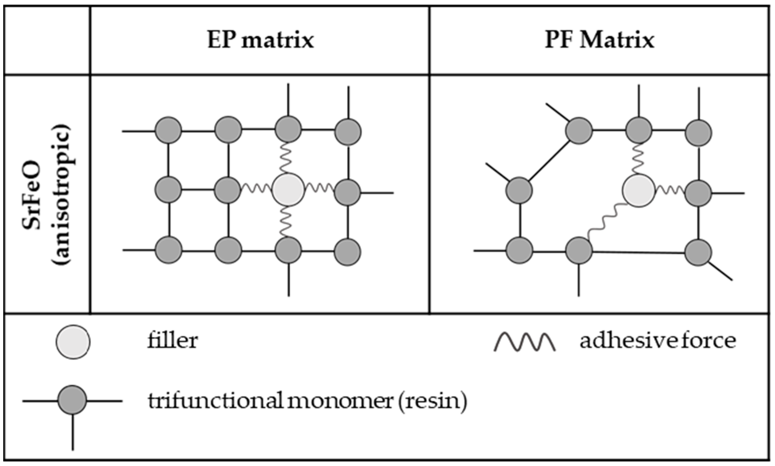
1.2. Fundamentals of Thermosets
1.3. Magnetic Properties
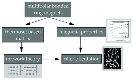
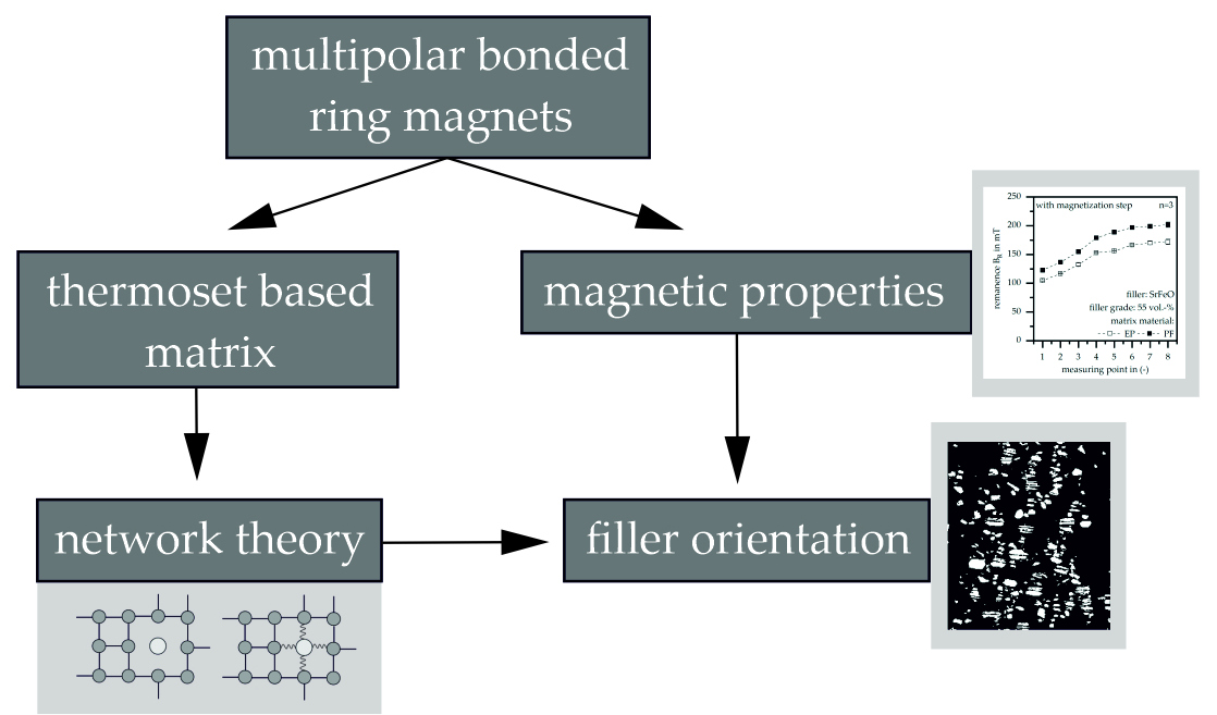
1.4. Aim of the Paper
2. Materials and Methods
2.1. Materials
2.2. Fabrication of the Test Specimens
2.3. Characterisation
2.3.1. Differential Scanning Calorimetry (DSC) According to DIN EN ISO 11357 [26]
2.3.2. Determination of the Viscosity Behaviour Based on a Rotational Viscometer According to DIN EN 53019 [27]
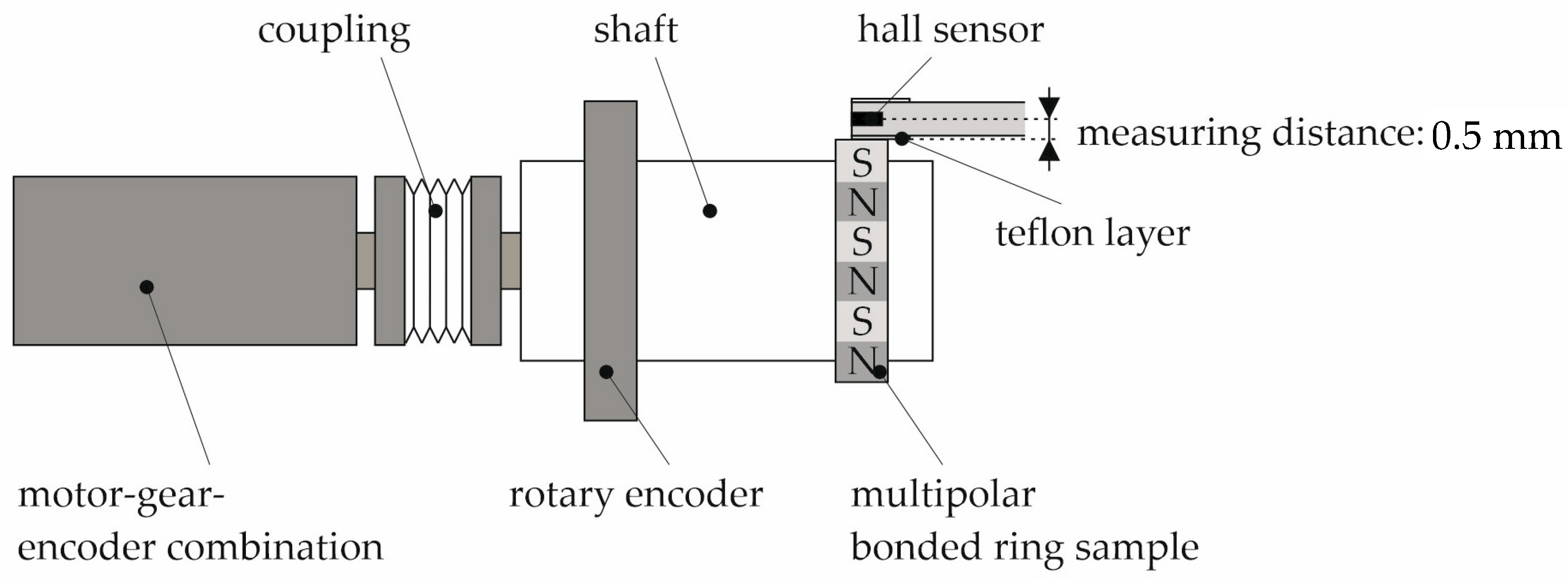
2.3.3. Magnetic Properties before and after Full Magnetisation
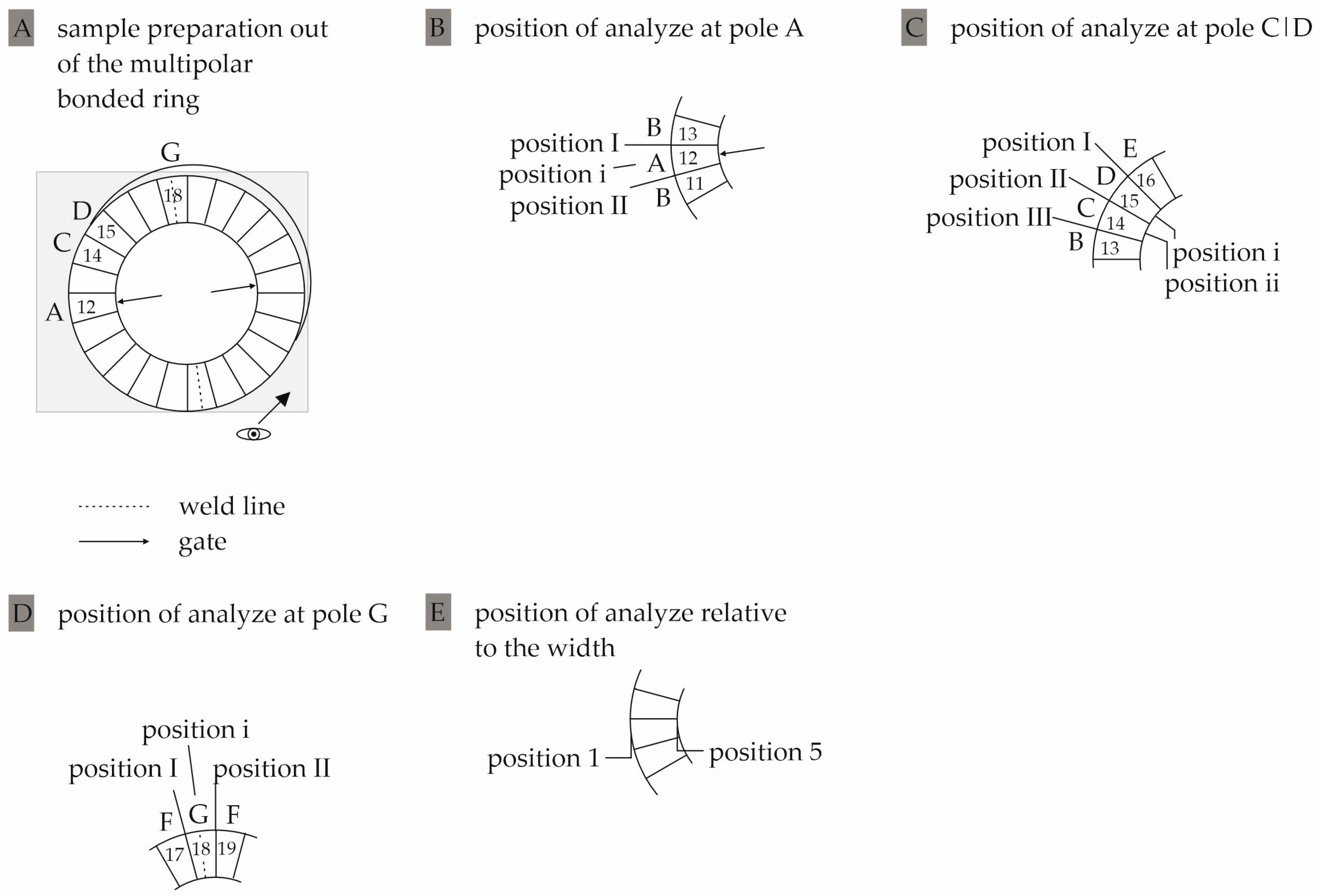
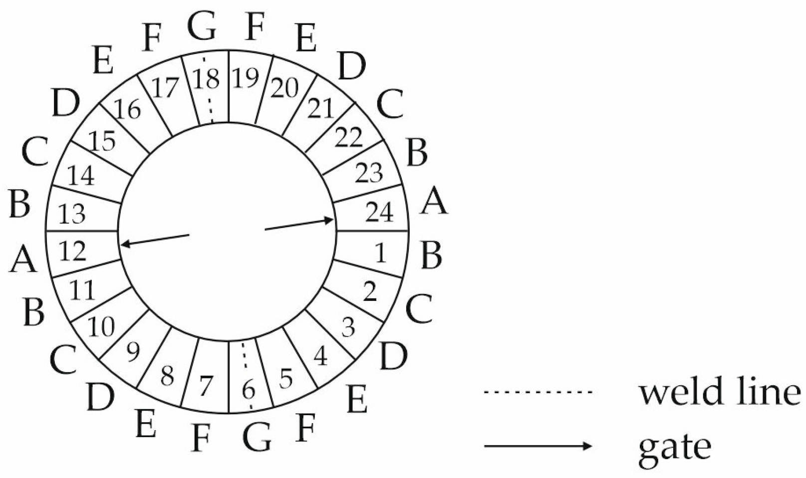
2.3.4. Determination of the Orientation of the Fillers
3. Results
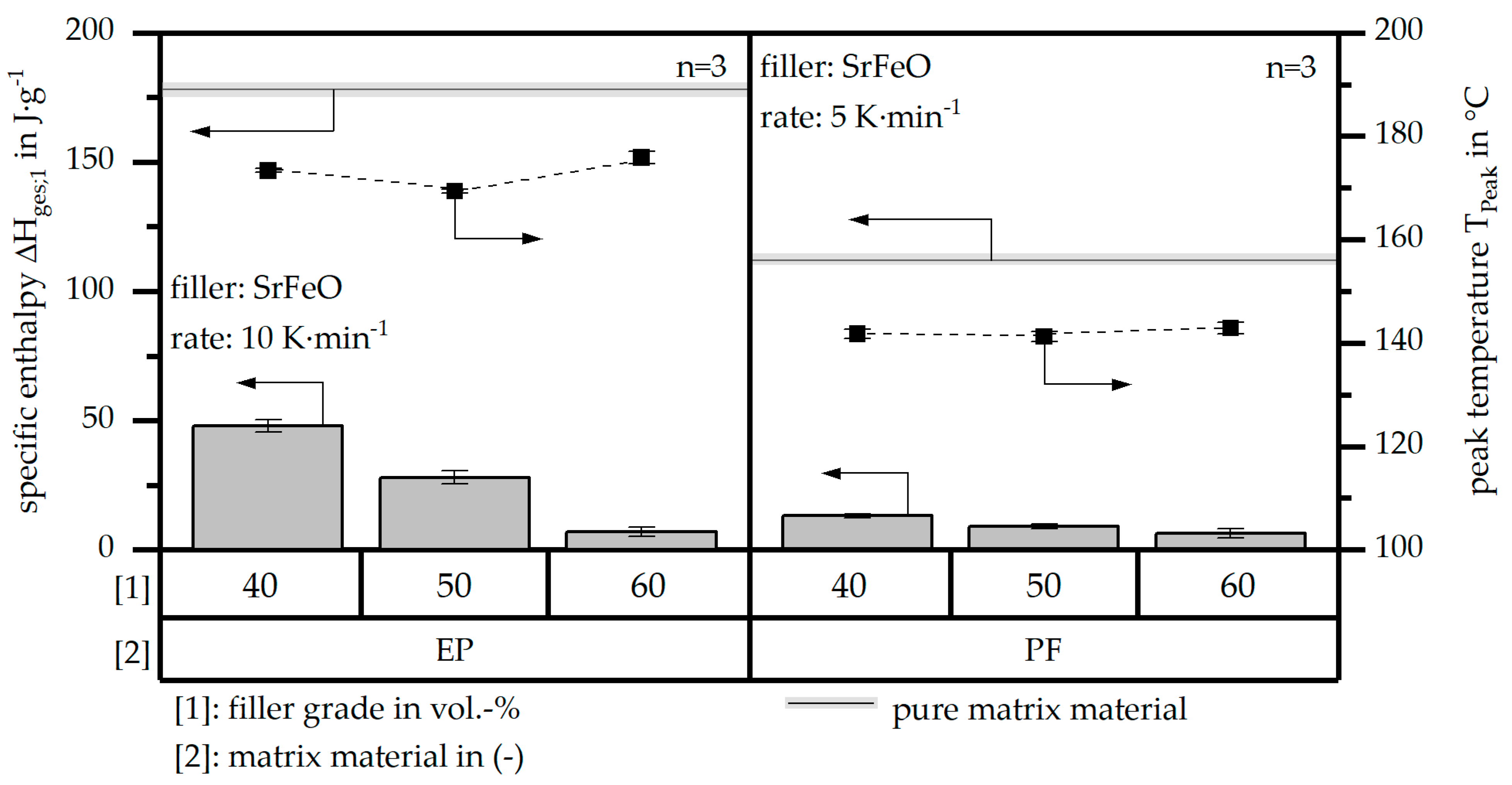
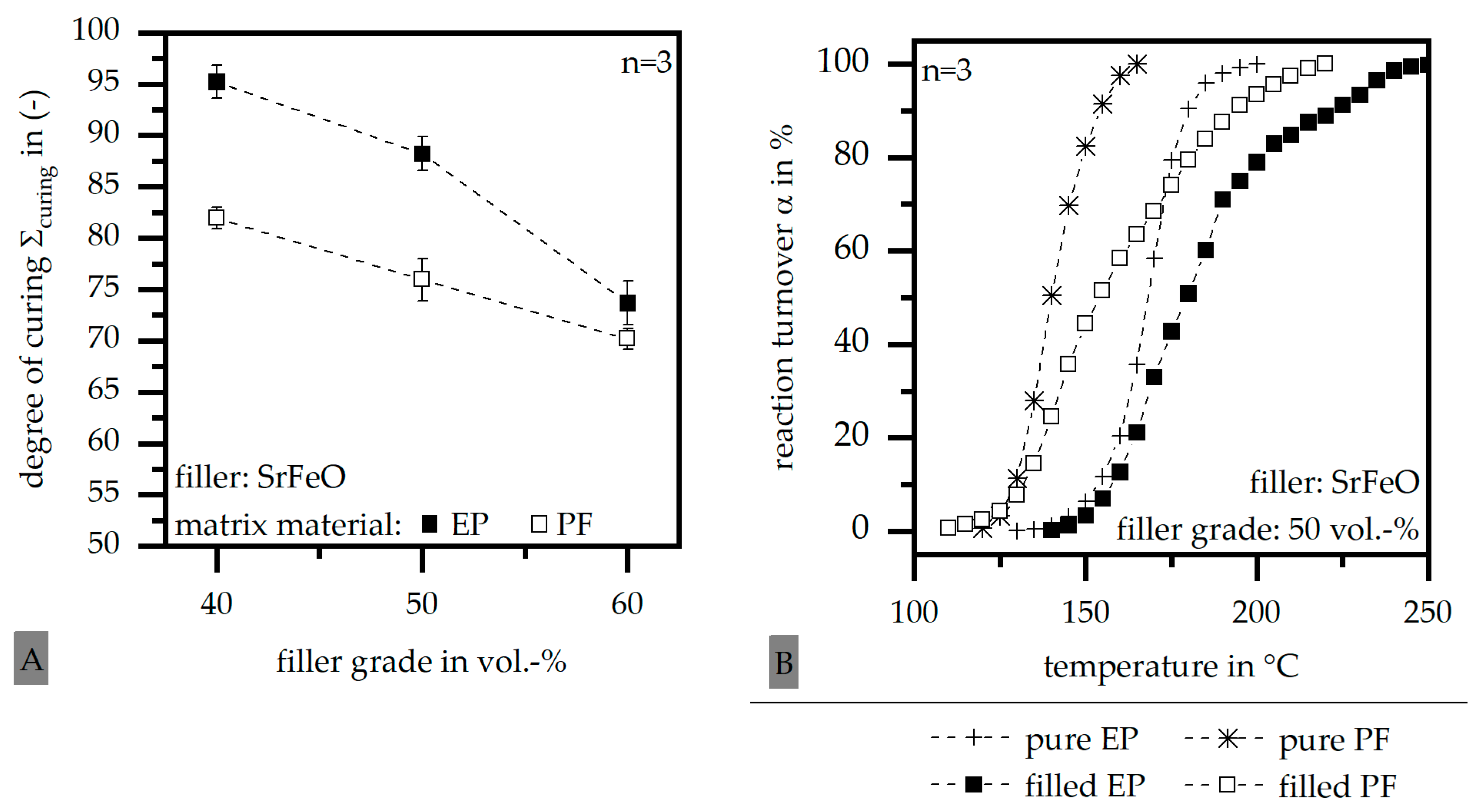
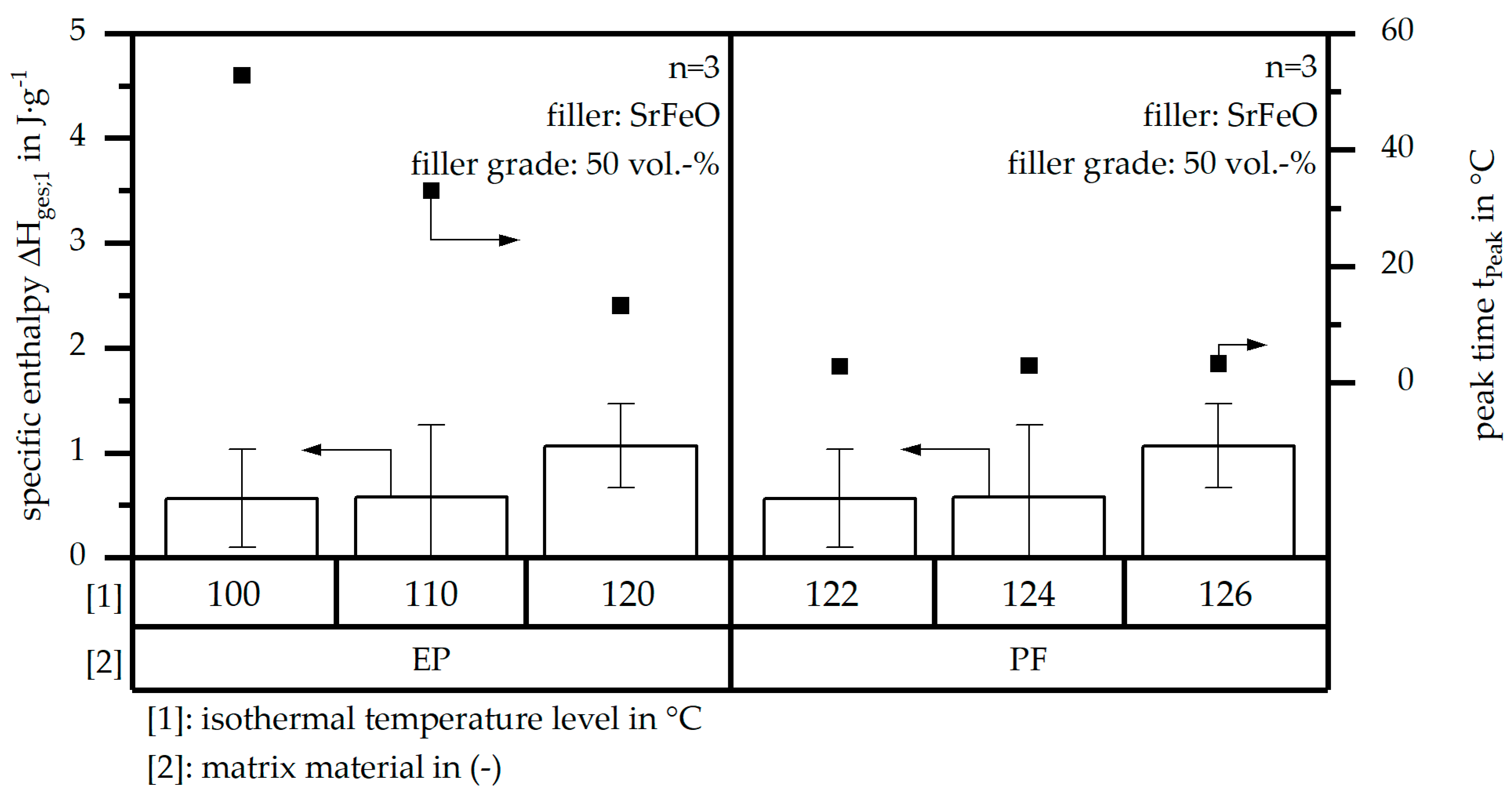
3.1. Reaction Kinetics Based on Differential Scanning Calorimetry (DSC)
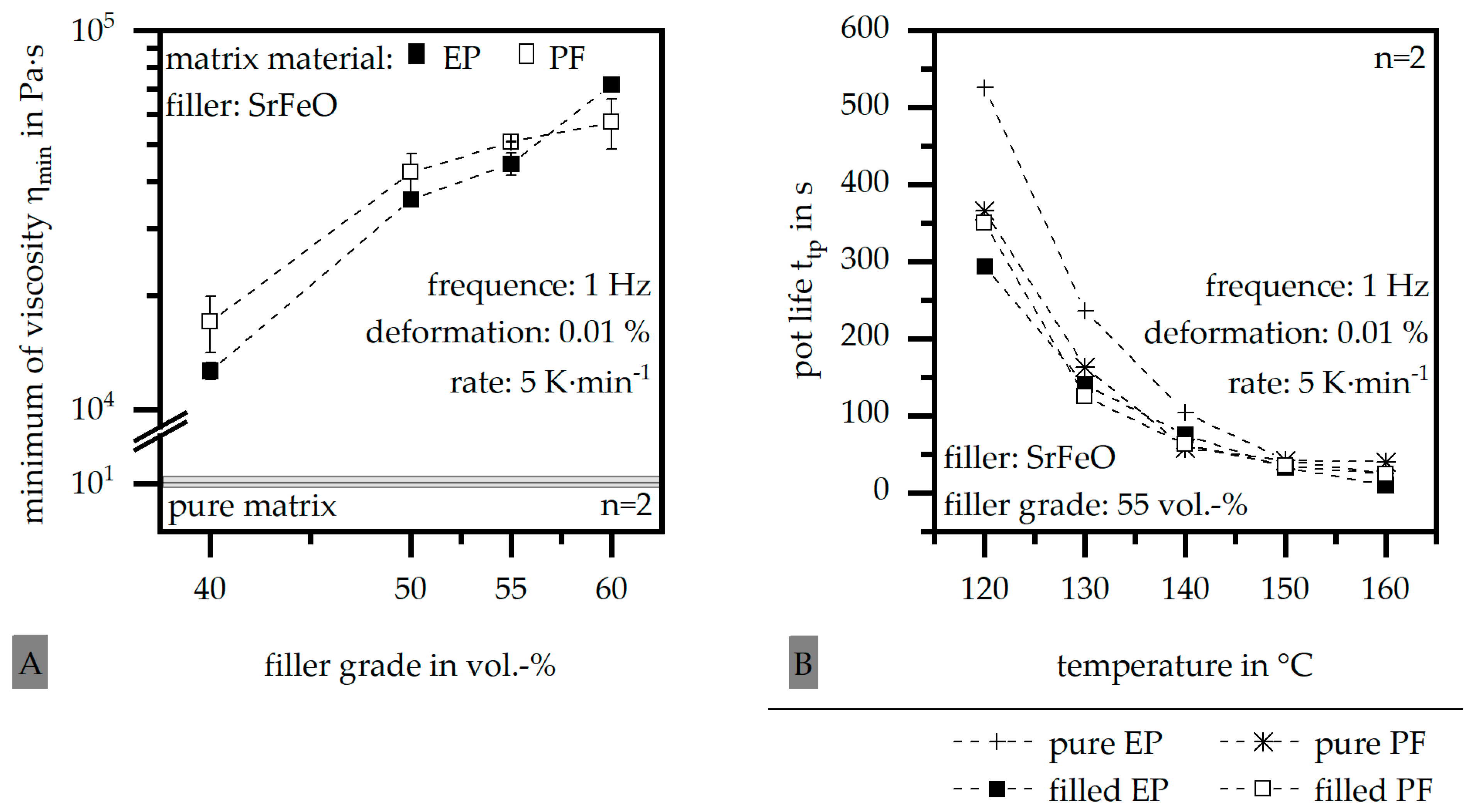
3.2. Viscosity Behaviour Based on Rotational Viscometer
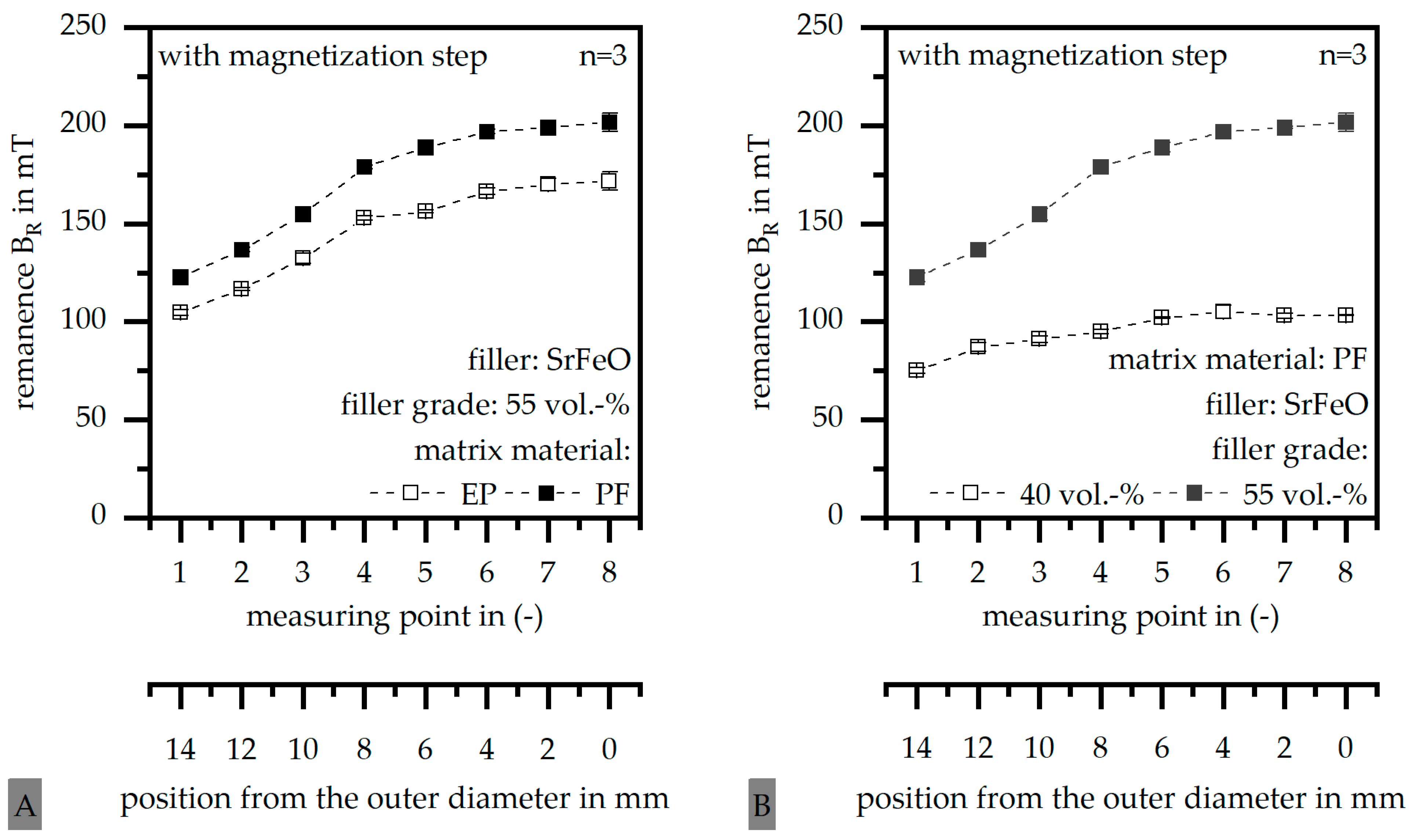
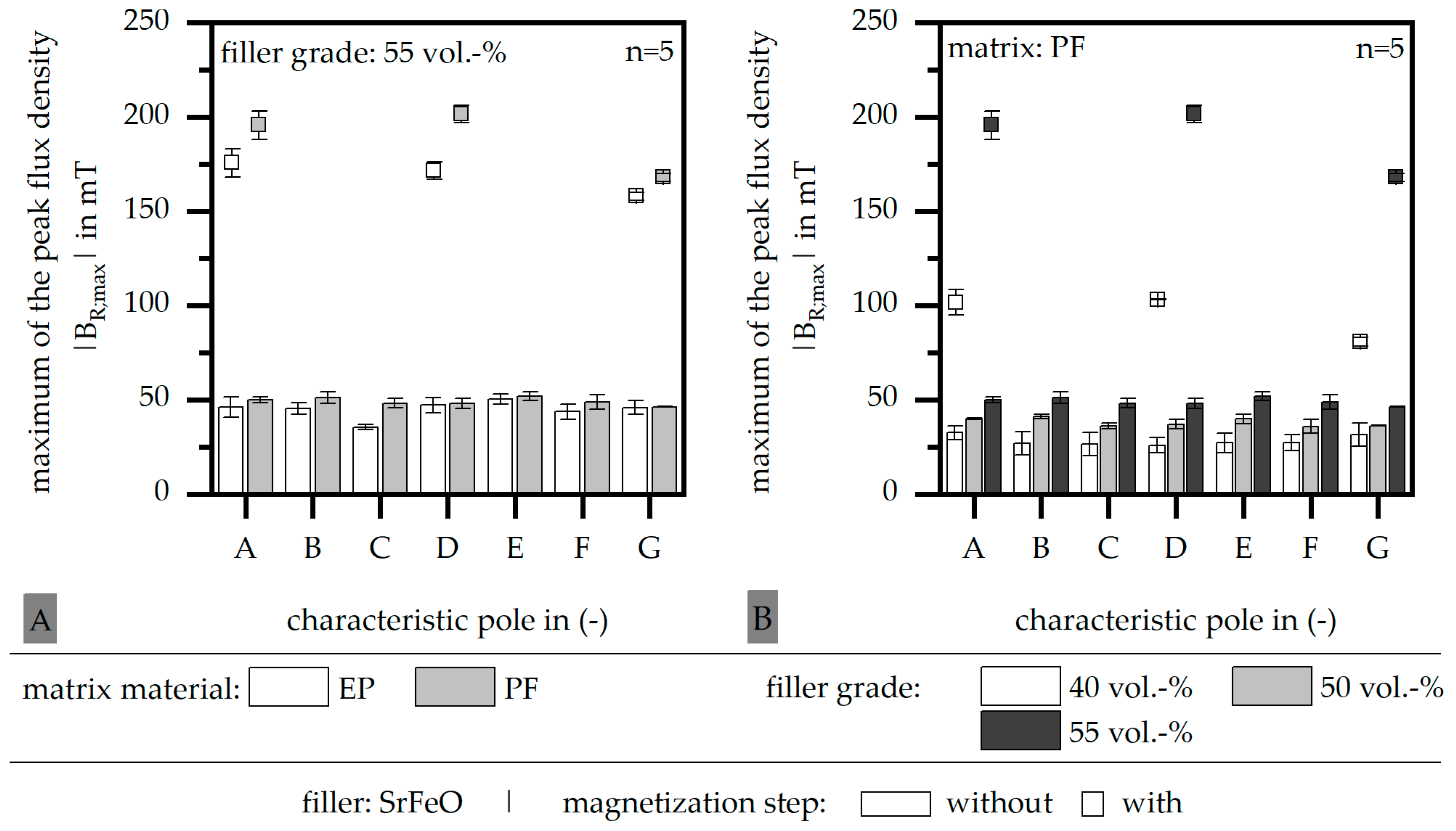
3.3. Magnetic Properties before and after Full Magnetisation
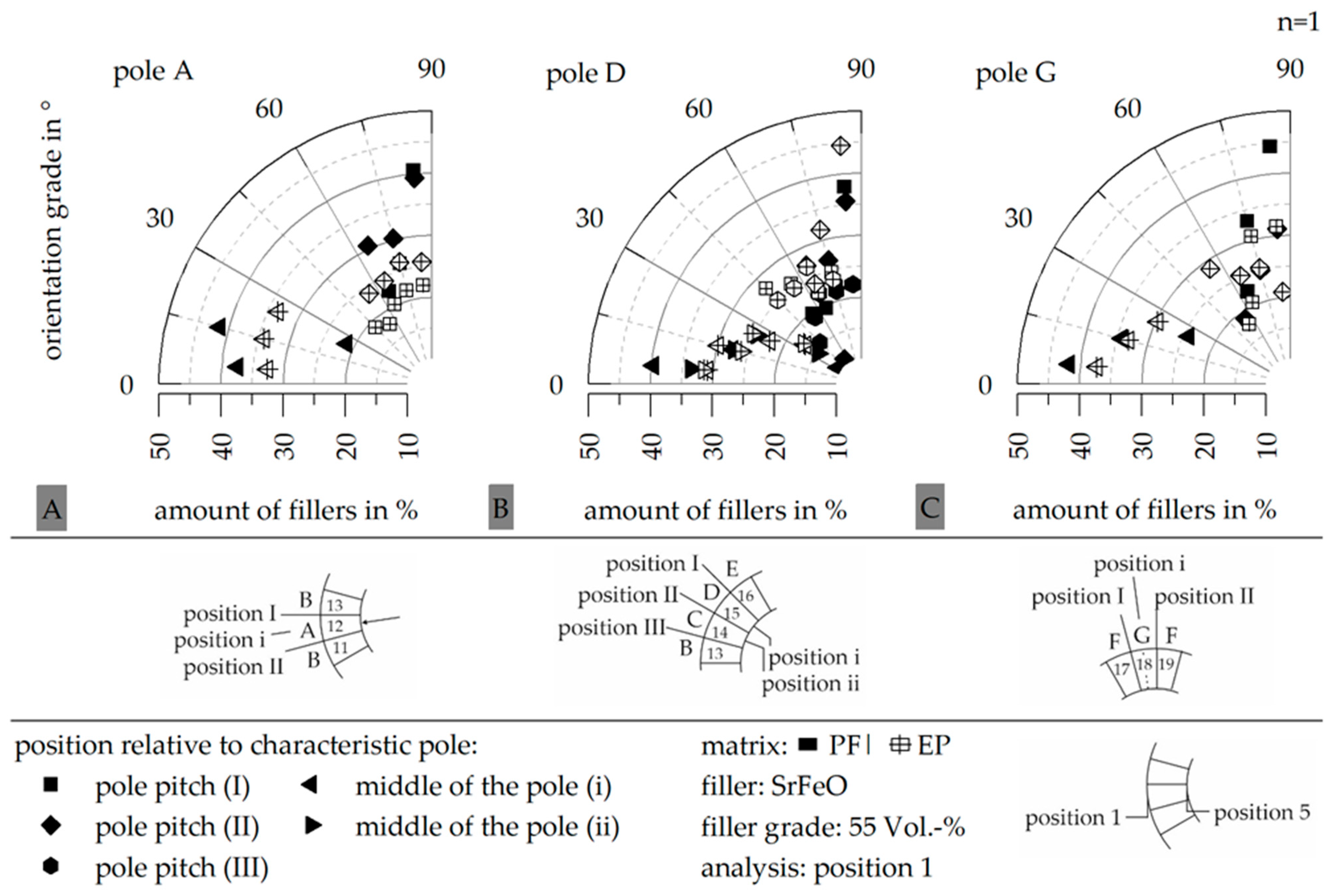
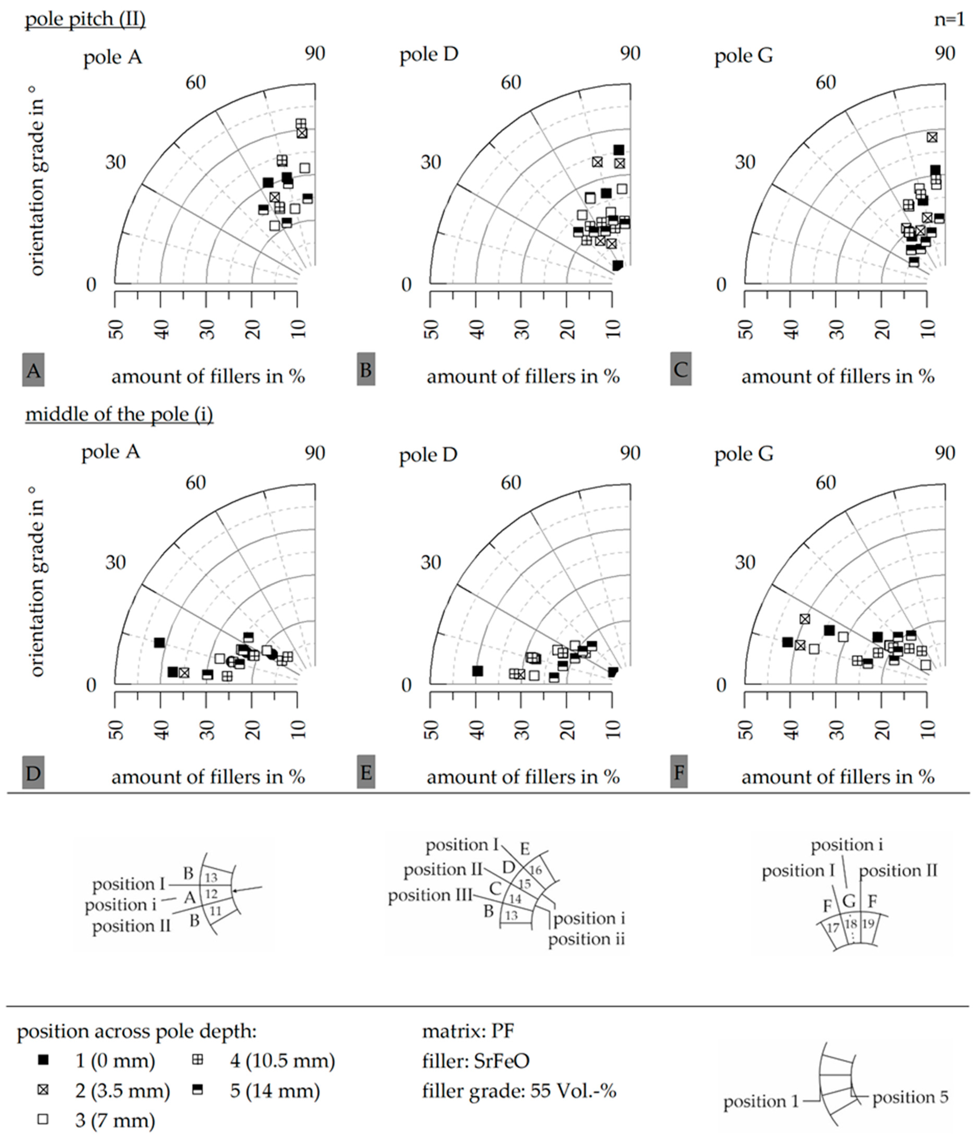
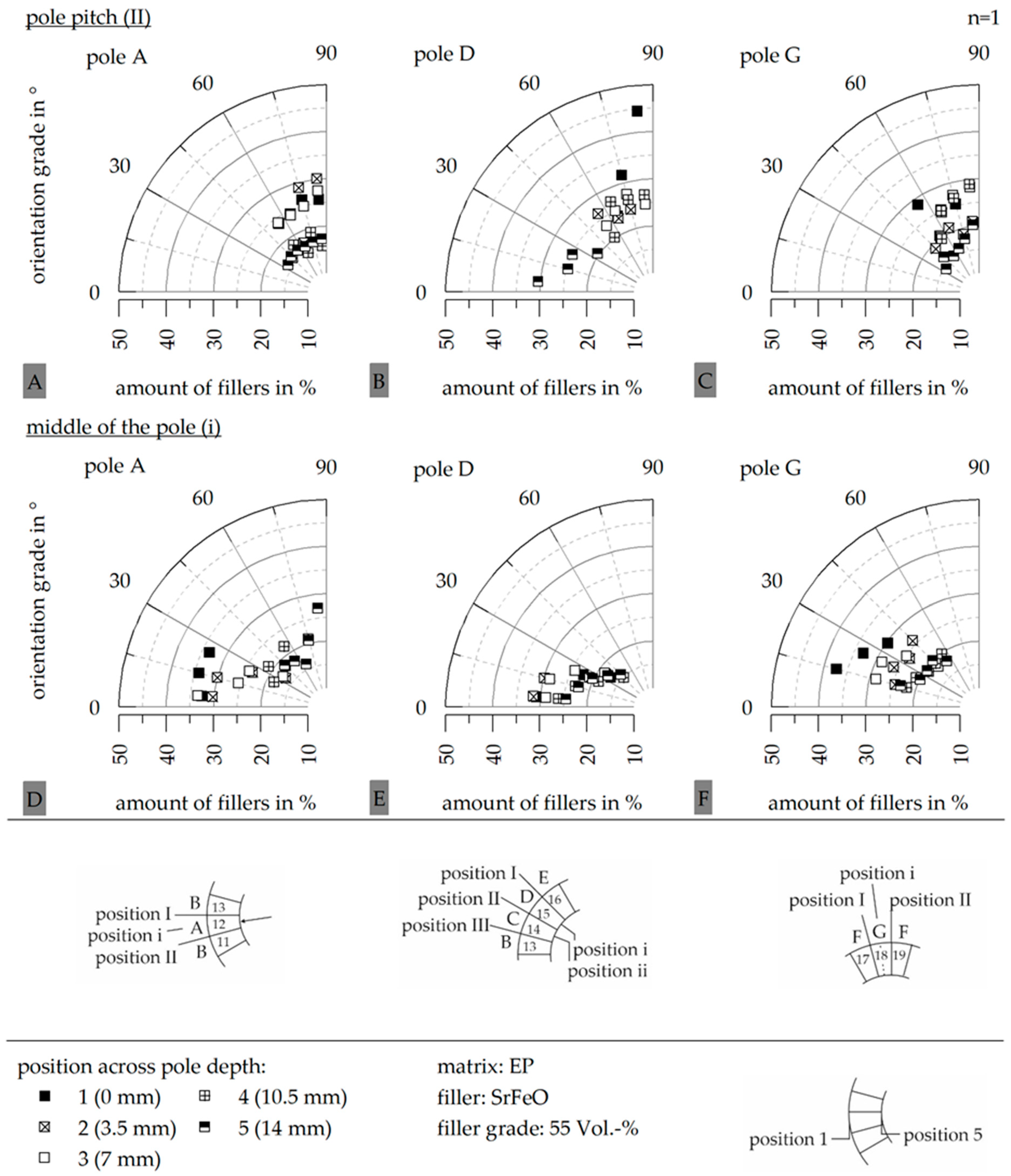
3.4. Hard Magnetic Filler Orientation
4. Discussion
5. Conclusions
Author Contributions
Funding
Institutional Review Board Statement
Informed Consent Statement
Data Availability Statement
Acknowledgments
Conflicts of Interest
References
- Cassing, W.; Kuntze, K.; Ross, G. Dauermagnete: Mess-und Magnetisierungstechnik, 3rd ed.; Expert-Verlag: Renningen, Germany, 2018. [Google Scholar]
- Reppel, G.W. Duroplastgepresste Magnete—Werkstoffe, Verfahren und Eigenschaften. In Kunststoffgebundene Dauermagnete: Werkstoffe, Fertigungsverfahren und Eigenschaften; Ehrenstein, G.W., Drummer, D., Eds.; Springer VDI Verlag: Düsseldorf, Germany, 2004; pp. 14–36. [Google Scholar]
- Drummer, D. Verarbeitung und Eigenschaften Kunststoffgebundener Dauermagnete. Ph.D. Thesis, Friedrich-Alexander-University, Erlangen, Germany, 2004. [Google Scholar]
- Kurth, K.H.; Drummer, D. Influences on the Magnetic Properties of Injection Molded Multipolar Rings. Int. Polym. Process. 2016, 31, 356–363. [Google Scholar] [CrossRef]
- Kurth, K. Zum Spritzgießen Polorientierter Kunststoffgebundener Dauermagnete. Ph.D. Thesis, Friedrich-Alexander-Universität Erlangen-Nürnberg, Erlangen, Germany, 2019. [Google Scholar]
- Hagemann, B. Kunststoffgebundene Magnete in der Antriebstechnik—Möglichkeiten und Grenzen. In Kunststoffgebundene Dauermagnete; Springer VDI Verlag: Düsseldorf, Germany, 2004. [Google Scholar]
- Altmann, N.; Halley, P.J.; Cooper-White, J.; Lange, J. The effects of silica fillers on the gelation and vitrification of highly filled epoxy-amine thermosets. Macromol. Symp. 2001, 169, 171–177. [Google Scholar] [CrossRef]
- Bae, J.; Jang, J.; Yoon, S.-H. Cure Behavior of the Liquid-crystalline Epoxy/Carbon Nanotube System and the Effect of surface treatment of carbon fillers on cure reaction. Macromol. Chem. Phys. 2002, 203, 2196–2204. [Google Scholar] [CrossRef]
- Dutta, A.; Ryan, M. Effect of fillers on kinetics of epoxy cure. J. Appl. Polym. Sci. 1979, 24, 635–649. [Google Scholar] [CrossRef]
- Wang, X.; Jin, J.; Song, M.; Lin, Y. Effect of graphene oxide sheet size on the curing kinetics and thermal stability of epoxy resins. Mater. Res. Express 2016, 3, 105303. [Google Scholar] [CrossRef] [Green Version]
- Halley, P.J. A new chemorheological analysis of highly filled thermosets used in integrated circuit packaging. J. Appl. Polym. Sci. 1997, 64, 95–106. [Google Scholar] [CrossRef]
- Altmann, N.; Halley, P.J. The effect of fillers on the chemorheology of highly filled epoxy resin: I. Effects on cure transitions and kinetics. Polym. Int. 2003, 52, 113–119. [Google Scholar] [CrossRef]
- Zhao, Z.; Zhanyu, Z.; Drummer, D. Thermal conductivity of alumininosilicate and aluminium oxide filled thermosets for injection molding. Polymers 2018, 10, 457. [Google Scholar] [CrossRef] [PubMed] [Green Version]
- Zhao, Y.; Drummer, D. Influence of filler content and filler size on the curing kinetics of an epoxy resin. Polymers 2019, 11, 1797. [Google Scholar] [CrossRef] [PubMed] [Green Version]
- Yushanov, S.P.; Isayev, A.I.; Levin, V.Y. Perolation simulation of the network degradation during ultrasonic devulcanization. J. Polym. Sci. Part B Polym. Phys. 1996, 34, 2409–2418. [Google Scholar] [CrossRef]
- Maenz, T. Spritzgießtechnische Herstellung Duroplastgebundener Dauermagnete. Ph. D. Thesis, Technical University Chemnitz, Chemnitz, Germany, 2018. [Google Scholar]
- Rösel, U.; Drummer, D. Correlation between the Flow and Curing Behavior of Hard Magnetic Fillers in Thermosets and the Magnetic Properties. Magnetism 2021, 1, 37–57. [Google Scholar] [CrossRef]
- Rösel, U.; Drummer, D. Understanding the effect of material parameters on the processability of injection-molded thermoset-based bonded magnets. Magnetism 2022, 2, 211–228. [Google Scholar] [CrossRef]
- Baur, E.; Brinkmann, S.; Osswald, T.; Rudoplh, N.; Schmachtenberg, E. Saechtling Kunststoff Taschenbuch, 31st ed.; Carl Hanser Verlag: München, Germany, 2013. [Google Scholar]
- Becker, G.W.; Braun, D. (Eds.) Kunststoff Handbuch: Duroplaste, 2nd ed.; Hanser: München, Germany, 1988. [Google Scholar]
- Normenausschuß Kunststoffe (FNK) im DIN Deutsches Institut für Normung e.V. Reaktionsharze, Reaktionsmittel und Reaktionsharzmassen; Beuth Verlag GmbH: Berlin, Germany, 1989; Available online: https://webstore.ansi.org/standards/din/din169451989de (accessed on 12 April 2022).
- Lechner, M.D.; Gehrke, K.; Nordmeier, E.H. Makromolekulare Chemie; Birkhäuser: Basel, Switzerland, 2003. [Google Scholar]
- Ormerod, J.; Constantinides, S. Bonded permanent magnets: Current status and future opportunities (invited). J. Appl. Phys. 1997, 81, 4816–4820. [Google Scholar] [CrossRef]
- Hering, E.; Martin, R.; Stohrer, M. Physik für Ingenieure, 12th ed.; Springer: Berlin/Heidelberg, Germany, 2016. [Google Scholar]
- Johannaber, F.; Michaeli, W. Handbuch Spritzgießen, 2nd ed.; Hanser: München, Germany, 2004. [Google Scholar]
- DIN EN ISO 11357-1:2016; Kunststoffe-Dynamische Differenz Thermoanalyse (DSC)-Teil 1: Allgemeine Grundlagen. Deutsches Institut für Normung e. V.: Berlin, Germany, 2016.
- DIN EN ISO 53019-1:2008; Viskosimetrie-Messung von Viskositäten und Fließkurven mit Rotationsviskosimetern-Teil 1: Grundlagen und Messgeometrie. Deutsches Institut für Normung e. V.: Berlin, Germany, 2008.


| Matrix Material | Density δ in g∙cm−3 | Heat Capacity c in J∙g−1∙°C−1 | Thermal Conductivity λ in W∙m−1∙K−1 | Peak Temperature Tpeak in °C |
|---|---|---|---|---|
| epoxy resin (EP) | 1.225 | 1.616 | 0.4–0.6 | 170.1 (1) |
| phenolic resin (PF) | 1.292 | 1.294 | 0.4–0.6 | 138.1 (2) |
| Hard Magnetic Filler | Density δ in g∙cm−3 | Heat Capacity c in J∙g−1∙°C−1 | Thermal Conductivity λ in W∙m−1∙K−1 | Mean Particle Size d50 in µm | |
|---|---|---|---|---|---|
| Numerical | Volumetric | ||||
| strontium-ferrite-oxide (SrFeO) | 5.380 | 0.639 | 2.3 | 4.87 | 1.94 |
| Process Conditions | EP | PF |
|---|---|---|
| mass temperature Tm in °C | 85 | 85 |
| mold temperature TWZ in °C | 190 | 180 |
| holding pressure ph in bar | 650 | 650 |
| heating time th in s | 200 | 45 |
| injection speed vin in mm∙s−1 | 15 | 15 |
Disclaimer/Publisher’s Note: The statements, opinions and data contained in all publications are solely those of the individual author(s) and contributor(s) and not of MDPI and/or the editor(s). MDPI and/or the editor(s) disclaim responsibility for any injury to people or property resulting from any ideas, methods, instructions or products referred to in the content. |
© 2023 by the authors. Licensee MDPI, Basel, Switzerland. This article is an open access article distributed under the terms and conditions of the Creative Commons Attribution (CC BY) license (https://creativecommons.org/licenses/by/4.0/).
Share and Cite
Rösel, U.; Drummer, D. Correlation between the Material System and the Magnetic Properties in Thermoset-Based Multipolar Ring Magnets. Magnetism 2023, 3, 226-244. https://doi.org/10.3390/magnetism3030018
Rösel U, Drummer D. Correlation between the Material System and the Magnetic Properties in Thermoset-Based Multipolar Ring Magnets. Magnetism. 2023; 3(3):226-244. https://doi.org/10.3390/magnetism3030018
Chicago/Turabian StyleRösel, Uta, and Dietmar Drummer. 2023. "Correlation between the Material System and the Magnetic Properties in Thermoset-Based Multipolar Ring Magnets" Magnetism 3, no. 3: 226-244. https://doi.org/10.3390/magnetism3030018
APA StyleRösel, U., & Drummer, D. (2023). Correlation between the Material System and the Magnetic Properties in Thermoset-Based Multipolar Ring Magnets. Magnetism, 3(3), 226-244. https://doi.org/10.3390/magnetism3030018