Article

Wearable Inductive Sensing of the Arm Joint: Comparison of Three Sensing Configurations

Department of Electrical and Computer Engineering, New York Institute of Technology, New York, NY 10023, USA
*
Author to whom correspondence should be addressed.
Magnetism 2022, 2(3), 195-210; https://doi.org/10.3390/magnetism2030015
Submission received: 6 May 2022 / Revised: 13 June 2022 / Accepted: 21 June 2022 / Published: 23 June 2022

Abstract

:
Currently, there is a rapidly growing interest and demand for wearable textile sensors that can monitor human motions in a naturalistic environment. Some potential applications for this technology include research on measuring the motor skill performance of patients with motor disabilities such as autism spectrum disorder, Parkinson’s disease, cerebral palsy, and stroke and evaluating the efficacy of applied treatments. Among wearable sensors, inductive sensors that are made from highly conductive threads are attractive due to their easy development process, high reliability, and low cost. In this study, we analyzed and compared the performance of three inductive wearable sensor configurations—(1) single planar rectangular coil, (2) two separated coils connected in series, and (3) two helical coils connected in series—in terms of the change in the resonant frequency of the tank circuit they comprised as a result of the change in elbow joint angle through simulations. Three parameters of length, width, and the number of turns were considered to calculate sensor sensitivity to the joint angle. The coil with the highest sensitivity was then fabricated and measured, and its performance was compared with the simulation results. The proposed methodology can be extended to sensing other joints in the body such as the shoulders, fingers, and knees.

1. Introduction

In recent years, wearable sensing devices have attracted great attention due to various application opportunities such as in soft robotics [1], health-related motion tracking and detection systems [2], and human–machine interfaces [3]. Such devices have been used to record data in order to analyze the activities of the participants wearing them [4]. For instance, autistic children face many perceptual integration challenges due to their motor planning problems, limited gesture performance, imitation praxis, and sensor reactivity [5]. Additionally, Parkinson’s disease (PD) manifests in motor and non-motor symptoms [6] The effects of the disruptions in the motor circuit can be seen in multiple brain activities, as well as during kinematic tasks.
Wearable devices [7,8], as their name implies, can be worn by patients without affecting their daily life activities. Due to advantages such as their small size, light weight, and ability to perform long-term monitoring, wearable sensors can operate with high efficiency and minimum discomfort.
There are many types of wearable sensors such as capacitive, resistive, stretchable, optical, and inductive sensors, which have been studied in the recent years for wearable and skin-mountable strain-sensing applications [9]. Each one of these technologies offers certain advantages and limitations. Below, we provide a brief discussion regarding these sensing techniques.
The working principle of stretchable resistive strain sensor [10] is based on mechanical strain, which leads to changes in electrical resistance. Despite the high sensitivity of this type of sensor, their main disadvantage is the mechanical deformation that directly affects electrical resistance; mechanical deformation can be caused by nominal operating heat, which makes these sensors difficult to use for long periods [11]. On the other hand, capacitive sensors have shown less hysteresis, more linear behavior, and faster responses. However, these sensors require a complex manufacturing process [12]. Lastly, optical strain sensors have demonstrated immunity to electromagnetic interference and electrical safety, but they have limitations in stretchability [13].
Among all wearable sensors, inductive textile sensors [14,15,16] are made from highly conductive threads, which enable the sensors to be sewn or attached to different surfaces. Moreover, conductive thread sewing technology has no limits regarding size and shape in contrast to commercially available inductive coils that have specific shapes such as rectangular, circular, pentagon, and octagon. Different coil geometries generate different magnetic fluxes. Thus, it is critical to find the optimal geometric design parameters [17,18,19], such as shape, size, gap between turns, number of turns, and the ratio of the inner to outer diameter of the coil in order to maximize sensor sensitivity.
It has been demonstrated by previous studies that inductive textile sensors made from conductive threads are sensitive to physical deformations. To respond to the high demand in the medical field, these sensors are made in a way such that they are practical for use by patients under particular treatments and track their motions in real time. Next, we review some of the major developments in this field. A three-dimensional (3D) knitted helical coil wrapped around the chest, which can be worn every day, was used for breathing monitoring in [20]. The same principle of the 3D knitted helical coil works for various other applications as well. For instance, by changing the dimension of the helical 3D coil, the garments can be worn on the arms, knees, fingers, etc., to measure the joint movements [21]. The folding of a two-dimensional (2D) planar coil can also be employed to measure joint movements [22]. In [23], another coil was sewn in a zig-zag pattern on a cloth. It was adjusted such that it was able to track trunk movements when the user bent forward, and it can especially be used by patients suffering from lower back pain.
In this work, we considered planar rectangular coils and helical wounded coils to measure soft angles—in particular, the angle of the elbow between the arm and forearm. Using planar coils [24], two different scenarios were designed; a single rectangular coil folding in the joint axis and two separated coils connected in series located on two sides of the elbow. For the former configuration, as the angle of the elbow joint varies, the self-inductance of the coil changes. For the latter configuration, as the angle of the elbow varies, the angle between the coils changes and, in turn, the mutual inductance caused by the magnetic flux of the first coil cutting through the second one changes, thus leading to a change in the total inductance. For a third design, the thread is sewed around the arm, forming a helix shape [25].
In general, inspired by the variety of shapes that easily can be sewn on cloth using conductive thread among many applications, we focused on designing a wearable inductive sensor that particularly works for sensing the angle of the elbow joint, as discussed above. The studied sensing configurations, however, can be adapted for other similar applications as well. Although various sensing configurations have been used in previous studies, there has been a lack of understanding regarding which sensing configuration provides the highest sensitivity, particularly for wearable textile applications due to the dimension constraints for these applications. Here, we aimed to design and compare three inductive sensing models that seem to be promising for further studies and analysis. Additionally, while previous works were mainly focused on studying inductance changes with the folding angle, we considered the resonant frequency change when the sensor was used in a resonant tank circuit. This consideration allowed for a more conclusive study about the level of accuracy of angle measurements in a practical measurement system.
The sensing principle is based on the resonant frequency of an LC tank circuit consisting of the self-capacitance (or self-capacitance plus an externally connected capacitance) and the inductance of a sewn coil. The magnetic flux of the sewn coil that is positioned on the elbow joint is changed by any physical deformation that changes from the initial position. As a result, the total inductance changes, consequently changing the resonant frequency of the tank circuit as well as. This change in the resonant frequency is the parameter that is employed to track the folding of the elbow. In some configurations, instead of one coil, two coils are placed in series, and their mutual position changes as the elbow joint angle varies. In this case, due to the change of the mutual inductance between the two coils, the overall inductance of the two coils in series changes, leading to a change in the resonant frequency of the tank circuit, as discussed above.
We used commercial simulation software to study the sensitivity of the proposed geometries. Based on these results, we were able to recommend optimal configuration and coil parameters. To observe varying of the inductance of the coils with the elbow joint angle, we employed a commercial inductance-to-digital converter that increased the sensitivity of the data acquisition by measuring the resonant frequency of a tank circuit comprising the sensing inductors. Lastly, the simulation results and experimental results were compared to validate the conclusions obtained from the simulation studies. The conclusion obtained here about the best sensing configuration for the elbow joint can be extended to the design of wearable coils for other joints on the body.

2. Methodology

In this section, we provide a comprehensive review of the wearable inductive sensing coil configurations that we used to measure arm movements. The sensing principle of an inductive sensor is based on the change of the inductance of the sensor coil while it experiences physical deformation due to the change of the joint angle α, as shown in Figure 1. To enable more sensitive data acquisition from an inductive sensor, it is common to construct a resonating tank circuit [26]. Thus, our approach was based on the frequency change for a sensitive resonant-sensing system. In this case, the LC tank circuit (the coil and any possible external capacitor) was connected to an LDC1614 data acquisition board that used to conduct the measurements, as shown in Figure 2. The resonant frequency f was then:
f = 1 2 π L C
To analyze the sensitivity of the proposed configurations, we considered the extent of the change in the resonant frequency when changing the arm angle from a minimum angle αmin to a maximum angle αmax (as shown in Figure 1).
For every sensing configuration discussed later using the formula of the resonant frequency in Equation (1), the tank circuit’s capacitor C was chosen such that we had a resonant frequency of fmin at angle αmin. Then, the same capacitor C was used to calculate the resonant frequency fmax at joint angle αmax (for which the inductance of the sensor would be different). The resonant frequency change Δf was then considered as:
Δ f = f m a x f m i n
For the each sensor design discussed below, we used Δ f instead of change of inductance as a figure of merit.
A sensor should be well-suited for clothes and should not impose inconvenience for the person wearing it. It has been reported that a planar rectangular (square) coil offers higher inductance compared to a circular coil if we consider the same outer diameter of circular coil and the outer length of the rectangular coil [27]. Below, we consider three sensing configurations.
The first scenario is a single planar rectangular coil (as shown in Figure 3) that is placed right at the elbow joint and folds as the angle of the elbow joint changes. Any change of the angle is shown as a deformation of the rectangular coil from its regular straight position; as a result, the self-inductance of the coil changes.
For the second and third designs, the inspiration came from a circuit comprising two inductors L1 and L2 connected in series, as shown in Figure 4. In these designs, the total inductance L t o t is obtained as:
L t o t = L 1 + L 2 ± 2 M
where M is the mutual inductance between the coils, and adding or subtracting depends on whether the coils are coupled in the same or opposite direction. The two coils are placed at two sides of the elbow. Then, as the angle between the inductors changes from αmin to αmax, the mutual inductance M between the coils changes, leading to a change in the total inductance of the two coils. The two coil shapes considered here to implement this idea were rectangular planar and helix coils, as shown in Figure 4b,c, respectively. We adjusted the size of the coils to the arm.

3. Simulation Results

In this section, we present the simulation results related to the optimization of the parameters of the three sensing configurations discussed in Figure 3 and Figure 4. Then, we analyze the effect of arm tissue on the performance of the sensors. We also compare the three sensors to conclude which configuration provides the best sensitivity. Finally, we compare the performance of the single- and double-layer folding coils.

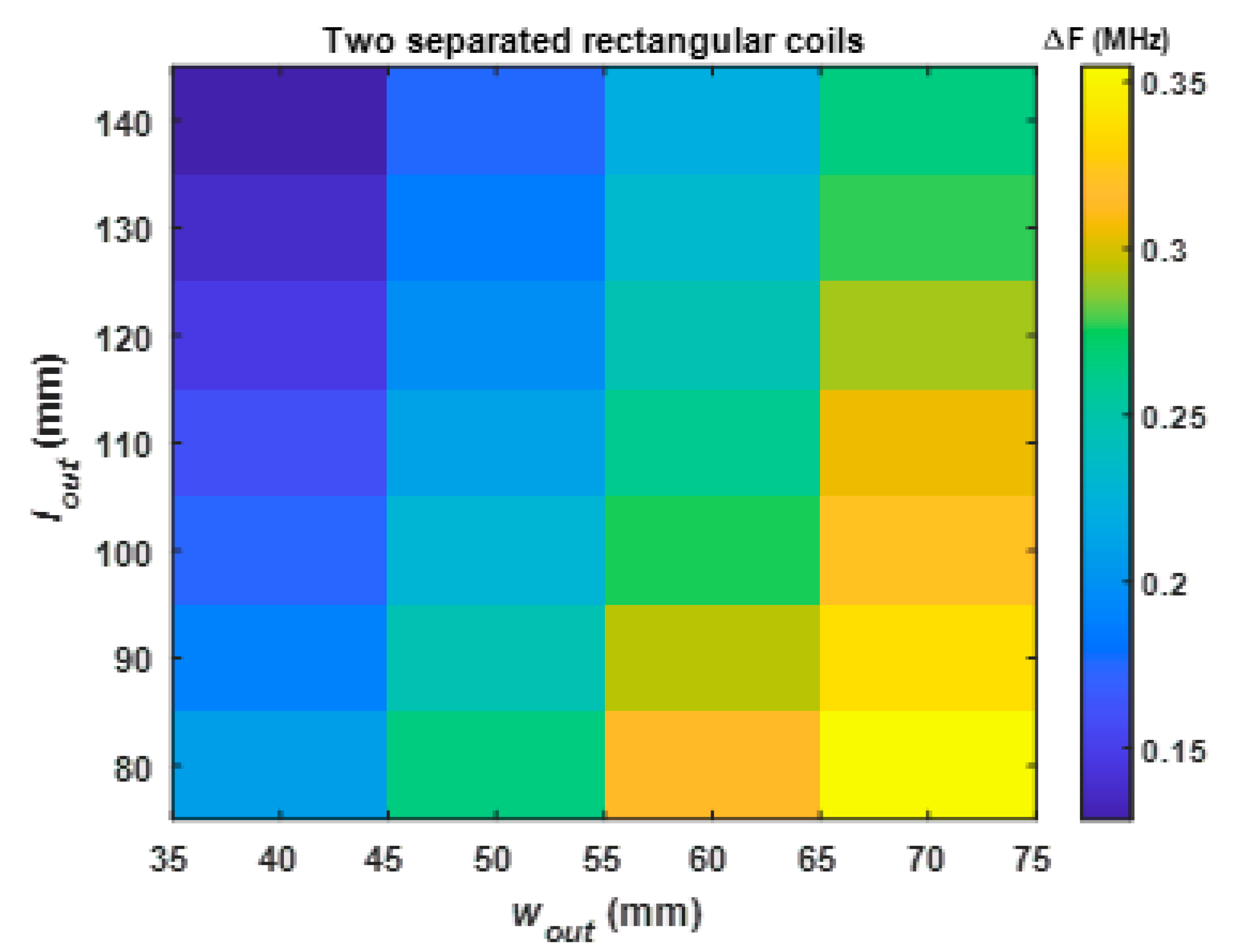
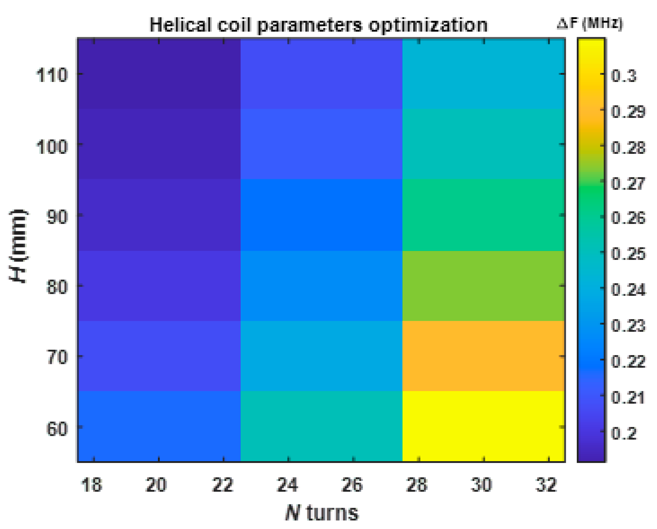
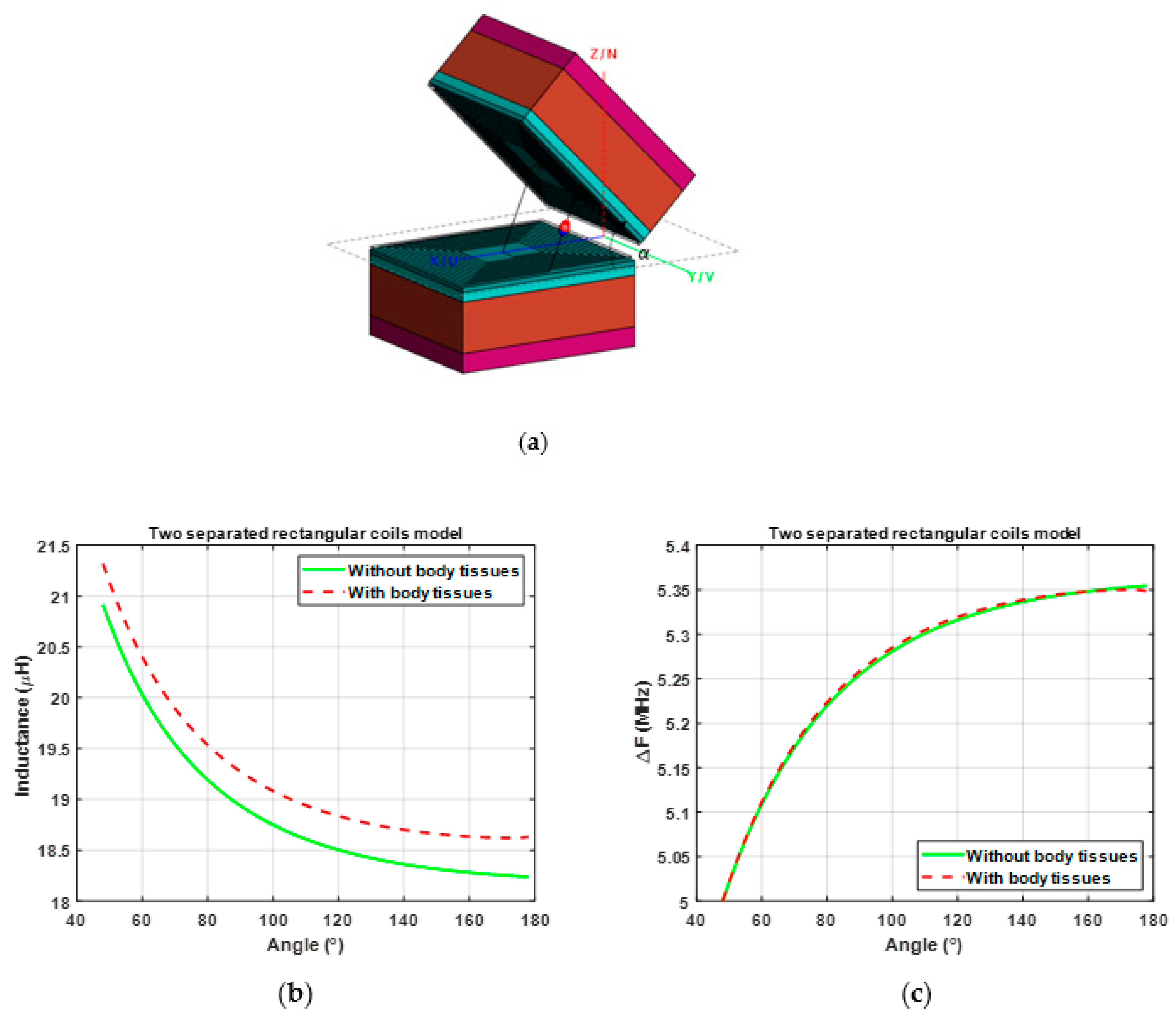
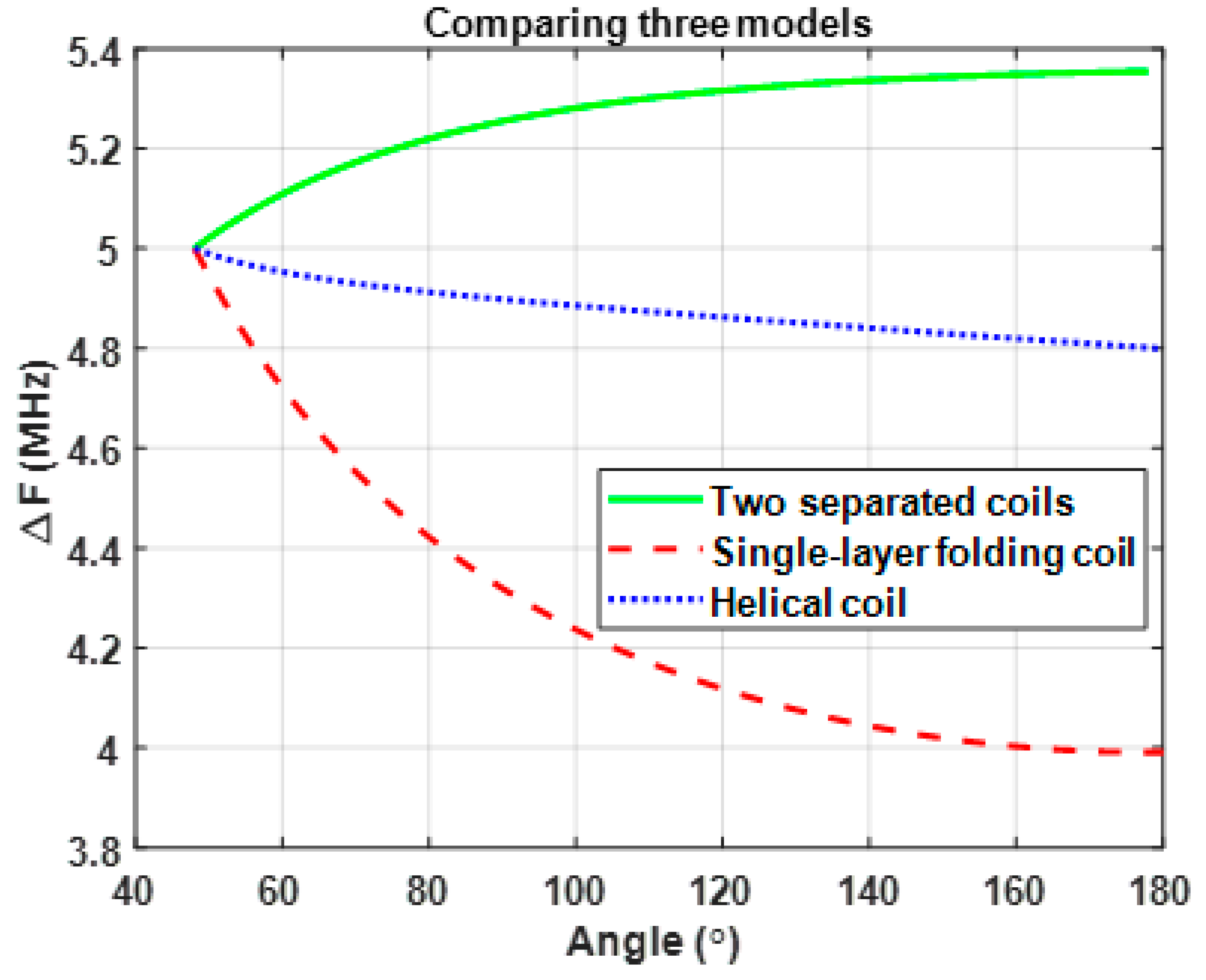
3.1. Parametric Study of the Sensing Configurations

In this section, we evaluate three coil designs in terms of sensing the angle of the elbow. To achieve a comprehensive comparison between the three designs, it was essential to find the optimal parameters that provided the highest Δ f in Equation (2). For this purpose, each model and respective parameters was designed with FEKO software v2021.1 [28], which is used for the simulation of electromagnetic problems. Since the coils are small compared to the wavelength corresponding to the simulation frequency (5 MHz was chosen), in FEKO, we set the low frequency method of moment (MoM) stabilization and double precision to achieve high-precision simulation results. FEKO provided the opportunity to run the models for different parameters and to analyze the data. By doing so, it was possible to find the optimal parameters for each model and to investigate the resonant frequency change over the angle, as discussed later. In particular, we verified that the FEKO results were close to the measurements of the sewed coils discussed in the next section. We used grid search in FEKO to generate all possible combinations of design parameters for the coils and obtain the imaginary impedance. The results were then compared in MATLAB R2021a [29]. In the experiments, we used a 3-ply stainless conductive thread with a diameter of 0.4 mm and a resistance of 1 ohm/inch produced by [30]. Thus, the resistivity of this thread used in the simulations were obtained using the following formula:
ρ = R × A l
where ρ is the resistivity of the thread, R is the resistance, A is the area of the cross section of the thread, and l is the length. The conductivity σ could be then obtained as:
σ = 1 ρ
Using (5), the conductivity σ of the thread was found to be 2.02 × 10⁵ S/m, which was used in the FEKO simulations.
To achieve a good quality factor, the ratio of the outer length versus the inner length and the ratio of the outer width by the inner width were kept constant, respectively, as lout/lin = 0.35 and wout/win = 0.30 [31]. To observe the impact of number of turns N, we simulated the first model of the single folding coil (see Figure 3) for 8, 10, and 12 turns. The maximum number of turns, N = 12, was chosen such that for the investigated coil dimensions, the gap between the turns could be still controlled satisfactory while sewing the coils (with fixed dimensions lout and wout, the gap between the turns grew smaller with the increase in N, thus increasing the difficulty of the sewing job). The minimum gap size was around 2 mm. The length and width were also limited because we were designing a wearable sensor that should be practically viable for an average arm size. There, it seemed reasonable to vary the length from 80 mm to 140 mm and the width from 40 mm to 70 mm.
After practicing bending of the arm while trying to avoid any possible short circuit that might be caused by the direct contact between the coils/turns, we chose the minimum angle of bending αmin = 46°. The maximum angle, when the hand was in the straight position, was set as αmax = 180°.
The FEKO simulation impedance values were analyzed for each of three coil configurations by sweeping the design parameters at two angles of αmin = 46° and αmax = 180°. The simulation results were imported in MATLAB for further processing. For each coil configuration and each set of coil parameters, we found the proper value of the capacitance C (as explained in Section 2) so that given the value of the inductance of the coil at αmin, the corresponding tank circuit resonated at f m i n = 5 MHz. Then, the change of the resonant frequency Δ f was calculated using f m i n and f m a x , where f m a x was obtained from the inductance for the same coil configuration at αmax and C.
Figure 5 shows the results of Δ f computed for the first coil configuration (folding coil in Figure 3) when varying lout and wout. The bar on the side shows the value of frequency change in MHz. From αmax (where the coil was in a straight position) to αmin (where the coil was folded), the magnetic fields created by both half coils tended to cancel each other out, resulting in a smaller value of the total inductance. As it folded, the total inductance changed and was translated into resonant frequency change for the tank circuit. Additionally, as predicted, for a larger number of turns while keeping the ratios lout/lin and wout/win fixed, we obtained higher inductance values. Each graph shows that larger widths and a smaller lengths led to higher frequency changes. The folding axis of the single rectangular coil (as shown in Figure 3) was along the width dimension, which ˝cut˝ the coil into two equal halves with lengths of lout/2. Consequently, all turns of the rectangular coil were folded on their mid-point along the length dimension around the folding axis (they did not deform along the width dimension). It was demonstrated that the larger the width, the higher the inductance change (frequency change) over the angle. In other words, the width dimension was found to have a larger impact on the inductance change. As the coil folded, the elements along the width dimension grew closer. As a result, the mutual inductance increased. If the width became larger, then a stronger magnetic flux was generated by each element, resulting in a higher mutual inductance. Additionally, the shorter the length for the coil was, the closer the elements along the width could become when the coil folded. It is worth noting that similar observations were reported in [22]. The optimal parameters for this model were found to be a length (lout) of 80 mm, a width (wout) of 70 mm, and 12 turns.
The second model consists of two rectangular coils, located on two sides of the elbow, one on the arm and the other one on the forearm. The coils were connected in series (as shown in Figure 4b) with an edge-to-edge distance of 95 mm to prevent direct contact between them when the bending angle reached αmin = 46°. As shown in Equation (3), the total inductance depended on the mutual inductance between the coils, and that, in turn, depended on the elbow joint’s angle. The closer they became, the higher the mutual inductance and its effect on the total inductance. As demonstrated in Figure 5, for one folding rectangular coil, the model with 12 turns provided a higher frequency change, as calculated from the inductance at αmin and αmax. Consequently, in order to have a higher inductance and a stronger magnetic field produced by the first coil passing through the second coil (to have higher mutual inductance), we simulated the second model in Figure 4b with 12 turns. Figure 6 shows the results of Δ f computed for the second coil configuration (Figure 4b) when varying the length and width of the coils. It was observed that the highest frequency change was for the length of 80 mm and width of 70 mm. With fixed ratios of lout/lin and wout/win, increasing the length and width resulted in the gap between turns becoming larger every 10 mm, which also affected the self-inductance and mutual inductance. The minimum of length and width led to the smallest gap, so the coils produced stronger magnetic fields that led to larger mutual inductance values and thus Δ f when the angle changed from αmin to αmax.
The helical coil model is another configuration that we studied. Two helical coils sewed around the arm were connected in series, as shown in Figure 4c. The radius R of the helix was set to 40 mm based on an average arm radius. The design parameters in this case were H (the height of the helix that changed from 60 to 110 every 10 mm) and N (the number of turns that changed from 20 to 30 every 5 turns). Figure 7 shows the values of Δ f computed for the third coil configuration (Figure 4c) when varying H and N. The graph shows that the highest frequency change was achieved at a height of 60 mm and N = 30 turns due to the same reason described in the previous case (for Figure 6). In other words, for the same number of turns, as the length became smaller, the magnetic flux created by the first coil passing through the second one became stronger, leading to larger mutual inductance and thus larger Δ f .

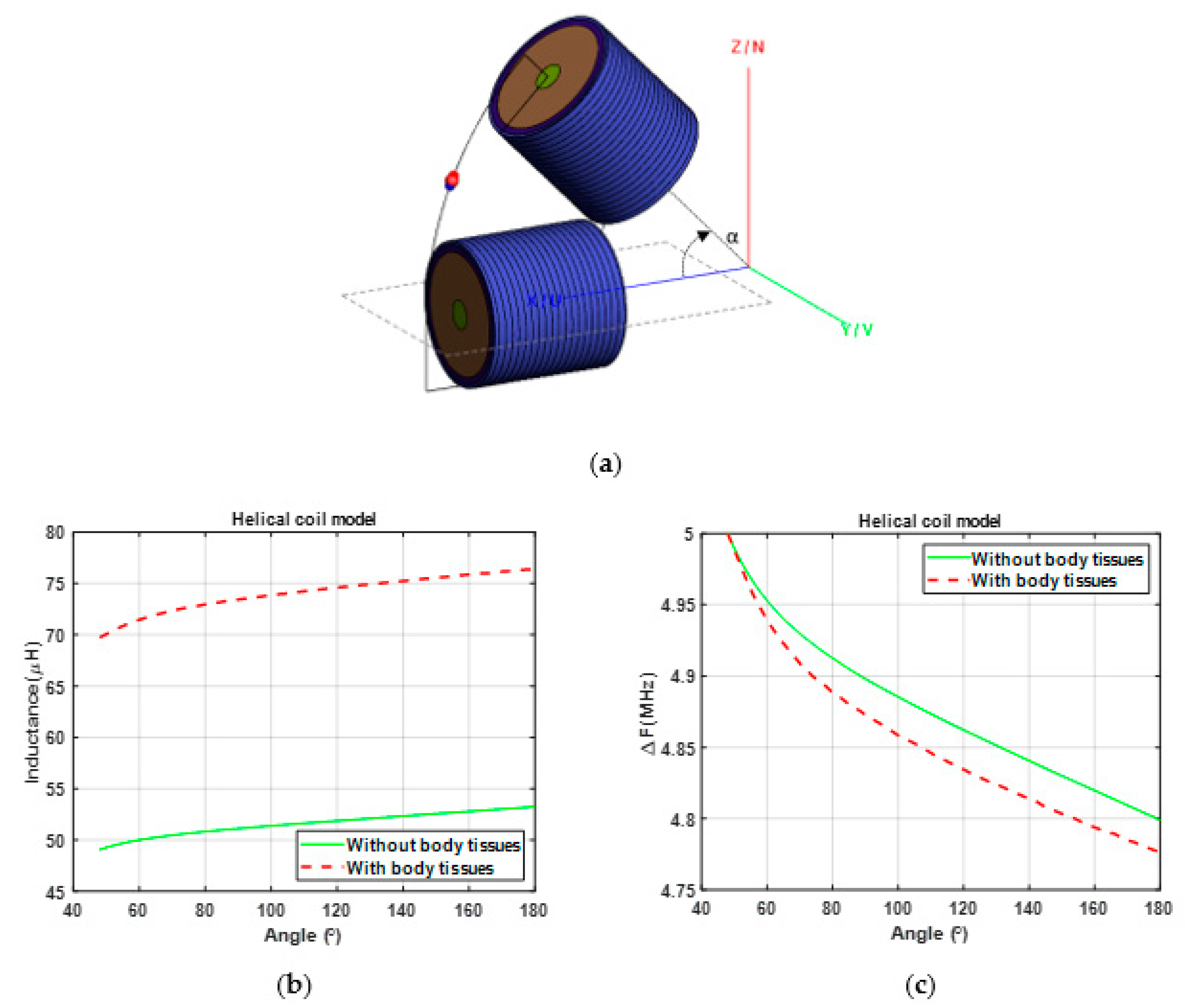
3.2. Effect of Arm Tissues

In addition the parameter optimization, it was necessary to study the effect of human body tissues because sensing coils will be placed in close proximity to the human body when a patient is wearing them. For this purpose, we added skin, fat, muscle, and bone layers to simulate the arm in FEKO [32].
We used the existing tissue models (electrical properties) in the FEKO library. Since human body tissues are dispersive (their electrical properties depend on the frequency), Table 1 shows the relative permittivity and conductivity at approximately 5 MHz.
The thickness of each layer depends on the person, but we considered a typical model with a skin thickness ls of 2 mm, a fat thickness lf of 4 mm, a muscles thickness lm of 21 mm, and a bone thickness lb of 8 mm. To observe the effect of arm tissues on the performance of the coils, we first compared the inductance over the joint angle for both models (with and without arm tissue) for the first coil configuration. We left a gap of 1 mm between the coil and the skin layer. Figure 8a shows the simulation model. As shown in Figure 8b, the inductance was higher when the coil was in the close proximity of the arm compared to the model without the presence of the arm. The same approach as before was applied to find Δ f . At αmin = 46°, capacitor C was set so that the tank circuit resonated at 5 MHz. This capacitance was then used to find the resonant frequency of the tank circuit as the angle α changed. Figure 8c compares the change of the resonant frequency for the models with and without the presence of the arm model. It could be observed that the values of Δ f were not significantly different in the two cases.
The same procedure was repeated for the second model (Figure 4b) to study the effect of arm tissues. Figure 9a shows the simulation model with the presence of the arm tissues in FEKO. The thickness of the tissues and the gap between the coils and the arm were the same as in the previous case. Like the previous case, Figure 9b,c presents comparisons of the variations of the inductance and Δ f versus the joint angle for the two models (with and without the arm tissue). It could be observed that the variations of Δ f were close.
For the last model, the conductive thread was sewed around the arm to form two coils, as discussed in Figure 4c. Hence, the arm model was designed as a cylinder with a radius of R = 40 mm and a length of H = 80 mm. The thickness of layers was kept the same as in the previous models except for the bone radius, which was set to 13 mm in order to adjust the helix radius to the arm radius. Figure 10b,c compares the variations of the inductance and Δ f versus the joint angle for the two models (with and without the arm tissue). It could be observed that the difference between the variations of Δ f were larger compared than those of the previous two cases.
Overall, it was observed that the total inductance of each model increased when the coil was in close proximity with the arm tissues. However, the extent of inductance increase depended on the area of the coil that was in proximity to the arm. For the first coil configuration in Figure 8, the area was smaller than that of the two separated coils and the helical coils. Figure 9b and Figure 10b demonstrate higher differences in inductance between the models without and with body tissues. However, the trends of the changes of the inductances in both models with and without the tissues were similar. Due to larger difference between the inductance with and without the tissue in the helix coil model, the resonant frequency changes in Figure 10c show larger deviations between the models with and without the tissues compared to those shown in Figure 8c and Figure 9c.
To summarize the analysis of three sensing configurations, Figure 11 shows the variation of the frequency change Δ f over the joint angle for the three configurations. Opposite behavior was observed for the models of the single-layer folding coil and two separated coils. Since the frequency response was inversely proportional to the inductance, when the inductance over the angle decreased, the resonant frequency increased and vice versa.
As stated above in the explanation of the single-layer folding model, as the angle became larger, the inductance increased due to the symmetric magnetic fluxes on two sides when the coil folded in the middle. The increase in inductance, in turn, led to the decrease in the resonant frequency (as shown in Figure 11). On the contrary, for the second configuration (two separated coils located on opposite sides of the elbow joint), the total inductance depended on the mutual inductance. In this case, we could control whether the mutual inductance was added or subtracted from the self-inductances of the coils to obtain the total inductance of the two coils in series. This was performed by determining the winding direction of the coils when they were connected. For the given model, coils were connected in such a way that their windings were in the same direction. So, the mutual inductance was added to the self-inductances of the coils to comprise the total inductance. Thus, as the angle became larger, the mutual inductance decreased, leading to a decrease in the total inductance. Figure 9b shows the relationship of inductance with the angle for this scenario. Following the above discussion, Figure 11 shows that as the angle grew larger, the inductance decreased and the resonant frequency increased. Lastly, Figure 10b shows that for the helical coil model, as the angle grew larger, the total inductance increased due to the mutual inductance between the two helical coils. The principle was the same as for the model of two separated coils, but in this model, the coils were connected in opposite directions. This led to the subtraction of the mutual inductance from the self-inductances of the coils when calculating the total inductance. The increase in the total inductance, in turn, led to a decrease in the resonant frequency.
This graph shows that the single rectangular coil model (in Figure 3) was the one with the highest frequency change over the angle and, therefore, the sensor with the best performance for measuring the angle of the elbow.

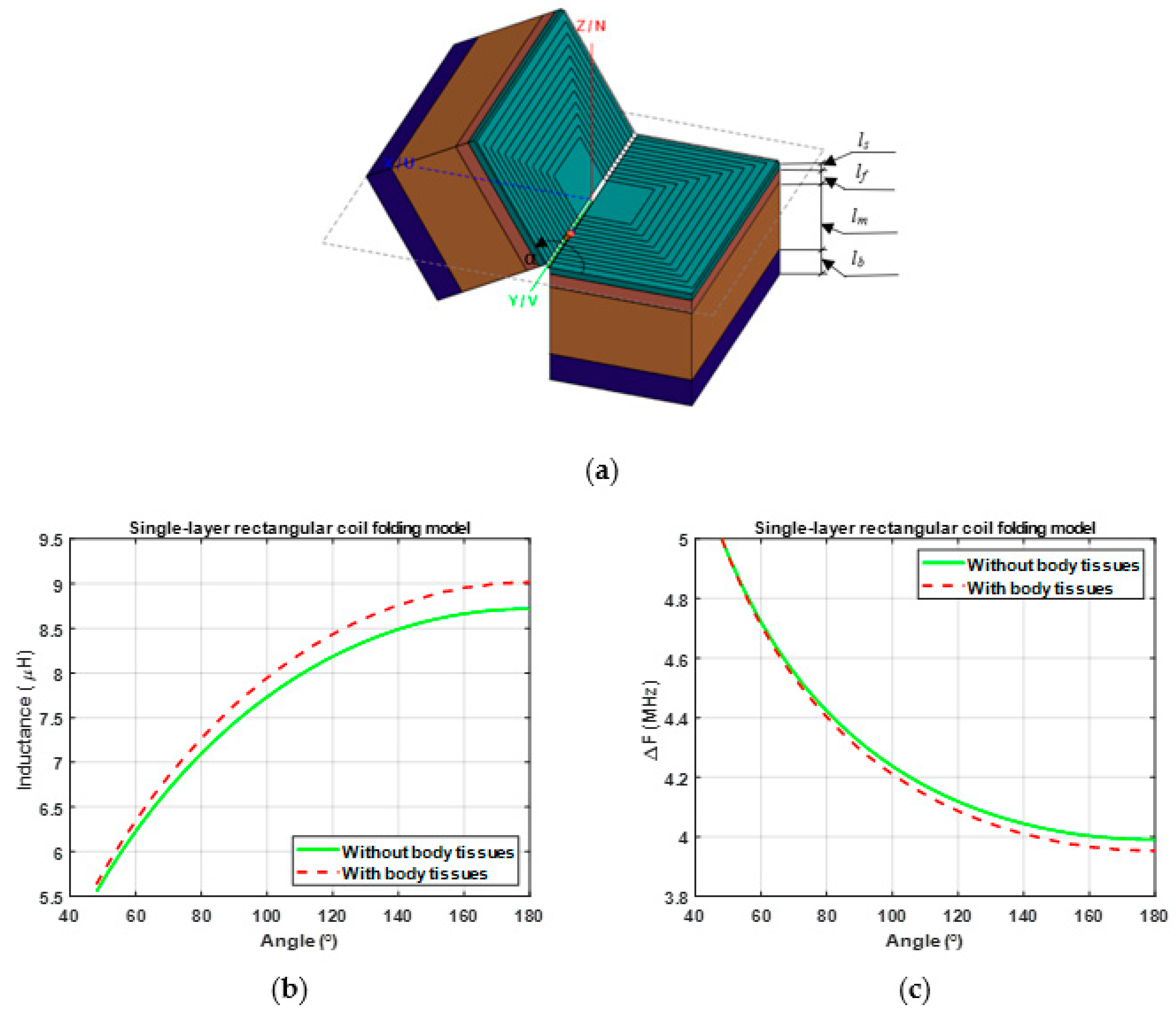
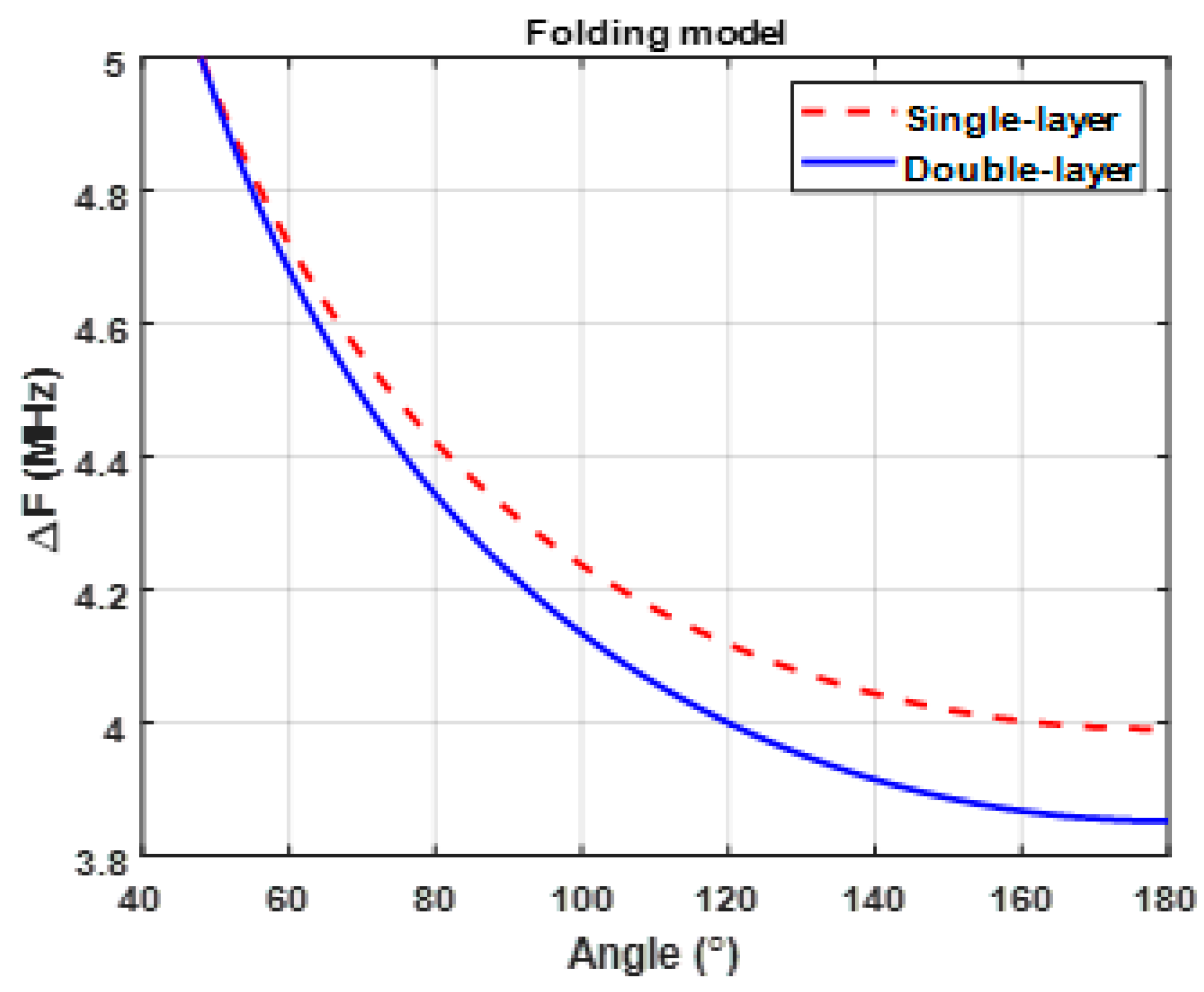
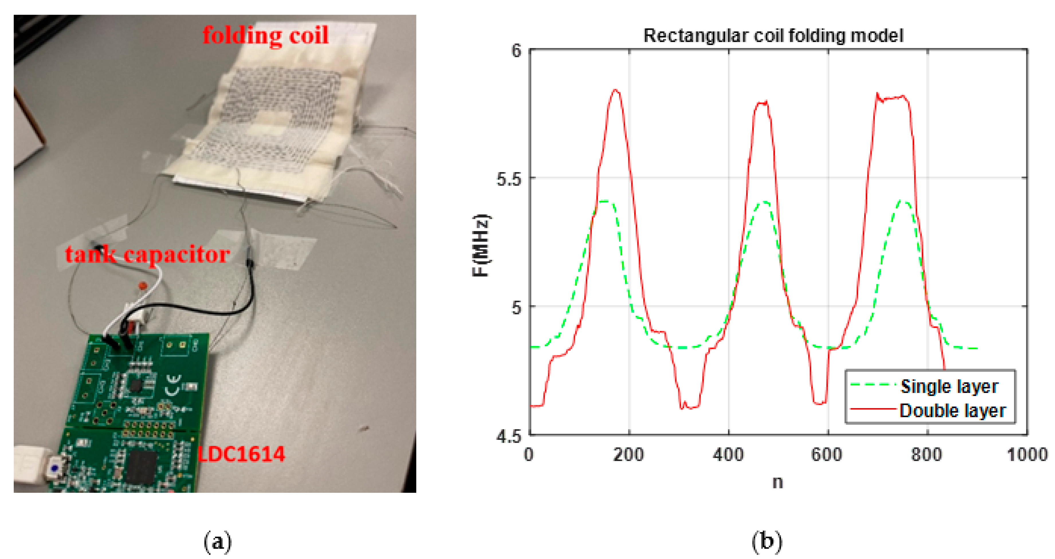
3.3. Comparing Single- and Double-Layer Folding Coils

Inspired by the results of one folding rectangular coil with the best performance among the three studied sensing configurations, we added one more layer with the same dimensions to create a two-layer folding coil. The connection was made based on the work of [31]; the second coil was flipped, and the connections between the coils were inner-to-inner and outer-to-outer terminals. This way, the current coming from the first layer went to the second layer following the same flow direction. Figure 12 shows the variation of Δ f over the joint angle for the two configurations of the one-layer and two-layer folding coils. This figure shows that the two-layer coil presented a higher variation for Δ f over the angle, which led to a more accurate measurement of the joint angle.

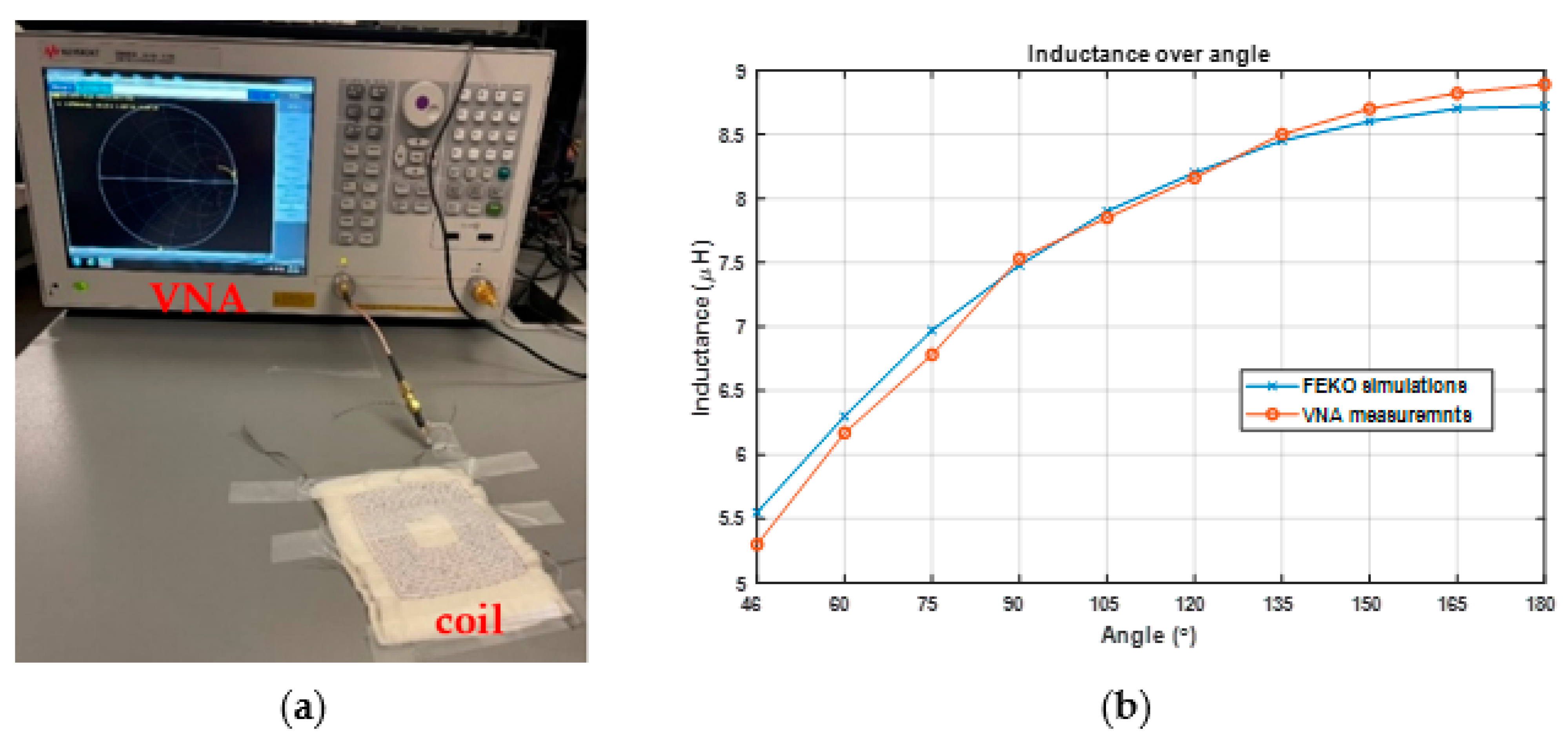
4. Experimental Results

For this section, we sewed single-layer and two-layer folding coils on pieces of fabric. The fabric used to sew the coils was 100% cotton for general use. We used fabric that was not stretchy in order to avoid any possible deformation and short circuits that could happen when the coil folded, as well as to make it easier to draw and sew the coil. Additionally, we used 3-ply stainless conductive thread with a diameter of 0.4 mm and a resistance of 1 ohm/inch produced by Adafruit [30]. The coils in this work were handmade. Typically, after a coil is drawn on fabric with a pencil and ruler, sewing is conducted using a needle and conductive thread.
From Figure 11, the folding coil showed the best performance of the three studied sensing configurations. The parameters of the sewed single-layer folding coil were a length of 80 mm and a width of 70 mm. In addition, the same dimensions were used to sew a two-layer coil, with the gap between the two layers set as thin as possible to make this sensing model more comfortable to wear.
First, to confirm the accuracy of the simulations, we connected the sensing coils to a vector network analyzer (VNA) (E5063A from Keysight) to measure the inductance of the coils, as shown in Figure 13a. The VNA was calibrated in order to remove the effect of the cable between the coils and the VNA’s port. The VNA was set to measure the impedance within the frequency range from 1 MHz to 10 MHz, and the measured inductance at frequency of 5 MHz was compared with the FEKO simulations. Table 2 and Figure 13b show the results of the FEKO simulations and VNA measurements for single folding rectangular coil. It was observed that the values of the simulated reactance and inductance matched well, although there were differences in the resistance values (probably due to inaccurate values of the conductivity reported for this commercial product or inaccurate cross section areas used to calculate the conductivity). Overall, the high-precision simulation of the inductance of the coils verified the accuracy of the simulations used to perform our studies.
For sensing applications (as shown in Figure 14a), we connected the coils to a Texas Instruments LDC1614 evaluation board, which is a highly sensitive inductance-to-digital convertor employed for inductive sensing applications [33]. The board measures the resonant frequency of a tank circuit that is built by connecting a capacitor in parallel to a sensing coil. To visualize the measurements, we used the Sensing Solution EVM GUI software [34]. When the one-layer coil was connected to the LDC1614 board, we connected a tank capacitor of 68 pF to generate a resonant frequency of around 5 MHz. For the two-layer coil, since the inductance was higher, a 10 pF capacitor was needed to generate a resonant frequency of 5 MHz. Figure 14b shows the variation of the resonant frequency over sample numbers for one-layer and two-layer coils and when the folding angles changed from 46° to 180° three successive times. The highest and lowest resonant frequencies were measured at the 180° and 46° angles, respectively. The frequency change of the one-layer coil was approximately 0.6 MHz, and that of the two-layer coil was approximately 1.2 MHz, which again proved that two-layer configuration was more sensitive to the change of joint angle and could better measure the angle of the elbow. According to the FEKO simulations (see Figure 12), the one-layer and two-layer coil values were 1 MHz and 1.6 MHz, respectively. The mismatch between the resonant frequencies of the FEKO simulations and LDC1614 measurements could have been due to the fact that parasitic capacitances of the coils and wires were neglected in the FEKO simulations.

5. Conclusions

In this paper, we have presented the design process of wearable inductive sensors with three configurations: (1) single planar rectangular folding coil, (2) two separated planar coils connected in series, and (3) two helical coils connected in series. The performance of the three configurations was evaluated and compared using FEKO software in terms of the change in the resonant frequency, Δ f , of the tank circuit that they comprised as a result of a changing elbow joint angle. Three design parameters of length, width, and the number of turns were considered to calculate the sensor sensitivity with and without body tissues. The purpose of adding body tissues was to study their effect on sensing performance because the sensing coils will be in close proximity to the human body. The results showed the single planar configuration had the highest sensitivity, with the maximum Δ f versus the joint angle of 1 MHz and the lowest variation of Δ f with respect to body tissues from FEKO simulations. The optimal parameters for this model were 80 mm for length, 70 mm for width, and 12 for the number of turns. We then evaluated the performance of folding configuration when an additional layer with the same dimensions was connected in series with the first layer to make a two-layer folding coil. The results showed that the two-layer configuration was more sensitive to the change in joint angle and could track the joint angle with a higher accuracy. Finally, we evaluated the performance of the fabricated one-layer and two-layer folding coils that were sewed on pieces of fabric with the optimal dimensions obtained from the simulations. The experimental results were in agreement with the simulation results, which proved the two-layer folding coil could measure the joint angle with the highest sensitivity. The designed coil can be used in a variety of applications such as tracking finger, knee, and shoulder movements.

Author Contributions

Conceptualization, R.K.A.; methodology, all authors; software, all authors; validation, all authors; formal analysis, all authors; investigation, all authors; resources, R.K.A. and M.R.; data curation, all authors; writing—original draft preparation, A.B.; writing—review and editing, R.K.A. and M.R.; visualization, all authors; supervision, R.K.A. and M.R.; project administration, R.K.A. and M.R.; funding acquisition, R.K.A. and M.R. All authors have read and agreed to the published version of the manuscript.

Funding

This project was supported by the 2022’s New York Institute of Technology’s Institutional Support for Research and Creativity (ISRC) Grant.

Conflicts of Interest

The authors declare no conflict of interest.

References

  1. Wyatt, F. Sensing Methods for soft Robotics. Ph.D. Thesis, Mechanical Enginnering, University of Michigan, Ann Arbor, MI, USA, 2017. [Google Scholar]
  2. Blachowicz, T.; Ehrmann, G.; Ehrmann, A. Textile-based sensors for bio signal detection and monitoring. Sensors 2021, 21, 6042. [Google Scholar] [CrossRef] [PubMed]
  3. Herbert, R.; Kim, J.-H.; Kim, Y.S.; Lee, H.M.; Yeo, W.-H. Soft Material-Enabled, Flexible Hybrid Electronics for Medicine, Healthcare, and Human-Machine Interfaces. Materials 2018, 11, 187. [Google Scholar] [CrossRef] [PubMed] [Green Version]
  4. Patel, S.; Park, H.; Bonato, P.; Chan, L.; Rodgers, M. A review of wearable sensors and systems with application in rehabilitation. J. Neuroeng. Rehabil. 2012, 9, 21. [Google Scholar] [CrossRef] [PubMed] [Green Version]
  5. Biscaldi, M.; Rauh, R.; Irion, L.; Jung, N.H.; Mall, V.; Fleischhaker, C.; Klein, C. Deficits in motor abilities and developmental frac-tionation of imitation performance in high-functioning autism spectrum disorders. Eur. Child Adolesc. Psychiatry 2013, 23, 599–610. [Google Scholar] [CrossRef] [PubMed]
  6. McLinden, J.; Deligani, R.J.; Abtahi, M.R.; Akbar, U.; Mankodiya, K.; Shahriari, Y. Disruptions of cortico-kinematic interactions in Parkinson’s disease. Behav. Brain. Res. 2021, 404, 113153. [Google Scholar] [CrossRef]
  7. Islam, G.M.N.; Ali, M.A.; Collie, S. Textile sensors for wearable applications: A comprehensive review. Cellulose 2020, 27, 6103–6131. [Google Scholar] [CrossRef]
  8. Zheng, Y.-L.; Ding, X.-R.; Yan Poon, C.-C.; Lai Lo, B.-P.; Zhang, H.; Zhou, X.-L.; Yang, G.-Z.; Zhao, N.; Zhang, Y.-T. Unobtrusive sensing and wearable devices for health informatics. IEEE Trans. Biomed. Eng. 2014, 61, 1538–1554. [Google Scholar] [CrossRef]
  9. Amjadi, M.; Kyung, K.U.; Park, I.; Sitti, M. Stretchable, skin-mountable, and wearable strain sensors and their potential applications: A review. Adv. Funct. Mater. 2016, 26, 11. [Google Scholar] [CrossRef]
  10. Chen, H.; Lv, L.; Zhang, J.; Zhang, S.; Xu, P.; Li, C.; Zhang, Z.; Li, Y.; Xu, Y.; Wang, J. Enhanced Stretchable and Sensitive Strain Sensor via Controlled Strain Distribution. Nanomaterials 2020, 10, 218. [Google Scholar] [CrossRef] [Green Version]
  11. Tan, C.; Dong, Z.; Li, Y.; Zhao, H.; Huang, X.; Zhou, Z.; Jiang, J.-W.; Long, Y.-Z.; Jiang, P.; Zhang, T.-Y.; et al. A high performance wearable strain sensor with advanced thermal management for motion monitoring. Nat. Commun. 2020, 11, 1–10. [Google Scholar] [CrossRef]
  12. Atalay, O. Textile-Based, Interdigital, Capacitive, Soft-Strain Sensor for Wearable Applications. Materials 2018, 11, 768. [Google Scholar] [CrossRef] [PubMed] [Green Version]
  13. Guo, J.; Niu, M.; Yang, C. Highly flexible and stretchable optical strain sensing for human motion detection. Optical 2017, 4, 10. [Google Scholar] [CrossRef]
  14. Tavassolian, M.J.; Cuthbert, T.; Napier, C.; Peng, J.Y.; Menon, C. Textile-based inductive soft strain Sensors for fast frequency movement and their application in wearable devices measuring multiaxial hip joint angles during running. Adv. Intell. Syst. 2020, 2, 1900165. [Google Scholar] [CrossRef]
  15. Souri, H.; Banerjee, H.; Jusufi, A.; Radacsi, N.; Stokes, A.A.; Park, I.; Sitti, M.; Amjadi, M. Wearable and Stretchable Strain Sensors: Materials, Sensing Mechanisms, and Applications. Adv. Intell. Syst. 2020, 2, 39. [Google Scholar] [CrossRef]
  16. García Patiño, A.; Menon, C. Inductive textile sensor design and validation for a wearable monitoring device. Sensors 2021, 21, 225. [Google Scholar] [CrossRef]
  17. Mutashar, S.A.; Hannan, M.A.; Samad, S.; Hussain, A. Analysis and optimization of spiral circular inductive coupling Link for bio-implanted applications on air and within human tissue. Sensors 2014, 14, 11522–11541. [Google Scholar] [CrossRef] [Green Version]
  18. Gong, J.; Wu, Y.; Yan, L.; Seyed, T.; Yang, X.D. Tessutivo: Contextual interactions on interactive fabrics with inductive sensing. In Proceedings of the ACM Symposium on User Interface Software and Technology, New Orleans, LA, USA, 20–23 October 2019. [Google Scholar]
  19. Mehri, S.; Ammari, A.C.; Slama, J.B.H.; Rmili, H. Geometry Optimization Approaches of Inductively Coupled Printed Spiral Coils for Remote Powering of Implantable Biomedical Sensors. J. Sens. 2016, 2016, 1–11. [Google Scholar] [CrossRef]
  20. Kiener, K.; Anand, A.; Fobelets, W. Low Power Respiration Monitoring Using Wearable 3D Knitted Helical Coils. IEEE Sens. J. 2021, 22, 1374–1381. [Google Scholar] [CrossRef]
  21. Fobelets, K.; Panteli, C. Proceeding paper ambulatory monitoring using knitted 3D helical coils. Eng. Proc. 2022, 15, 6. [Google Scholar]
  22. Wang, H.; Totaro, M.; Veerapandian, S.; Ilyas, M.; Kong, M.; Jeong, U.; Beccai, L. Folding and Bending Planar Coils for Highly Precise Soft Angle Sensing. Adv. Mater. Technol. 2020, 5, 11. [Google Scholar] [CrossRef]
  23. García Patiño, A. Design and development of a wearable inductive textile sensor to monitor back movements. Sensors 2020, 20, 905. [Google Scholar] [CrossRef] [PubMed] [Green Version]
  24. Poliakine, J.; Civet, Y.; Perriarda, Y. Design and manufacturing of high inductance planar coils for small scale sensing applications. Proced. Eng. 2016, 168, 1127–1130. [Google Scholar] [CrossRef]
  25. Wijesiriwardana, R. Inductive fiber-meshed strain and displacement transducers for respiratory measuring systems and mo-tion capturing systems. IEEE Sens. J. 2006, 6, 3. [Google Scholar] [CrossRef]
  26. Yu Sh, Y.; Chen, R.; Viswanathan, A. In Proceedings of the Survey of resonant converter topologies. Texas Instruments Power Supply Design Seminar SEM, Dallas, Texas. 2018, p. 2300. Available online: https://www.ti.com/seclit/ml/slup376/slup376.pdf (accessed on 4 May 2022).
  27. Aldoumani, M.; Yuce, B.; Zhu, D. Using the variable geometry in a planar inductor for an optimized performance. Electronics 2021, 10, 721. [Google Scholar] [CrossRef]
  28. Altair Feko. Available online: https://www.altair.com/feko/ (accessed on 4 May 2022).
  29. MATLAB. Available online: https://www.mathworks.com/products/matlab.html (accessed on 4 May 2022).
  30. Adafruit, Stainless Thin Conductive Yarn/Thick Conductive Thread-30 ft. Available online: https://www.adafruit.com/product/603#technical-details (accessed on 4 May 2022).
  31. Sensor Design for Inductive Sensing Applications Using LDC, Application Report, Texas Instruments, SNOA930C, May 2021. Available online: https://www.ti.com/lit/an/snoa930c/snoa930c.pdf?ts=1655864799663 (accessed on 22 June 2022).
  32. Forro, S.D.; Munjal, A.; Lowe, J.B. Anatomy, Shoulder and Upper Limb, Arm Structure And Function; Treasure Island (FL), StatPearls 2022. Available online: https://www.ncbi.nlm.nih.gov/books/NBK507841/ (accessed on 4 May 2022).
  33. LDC1612, LDC1614 Multi-Channel 28-Bit Inductance to Digital Converter (LDC) for Inductive Sensing. Available online: https://www.ti.com/product/LDC1614 (accessed on 4 May 2022).
  34. Sensing Solutions EVM GUI Tool v1.10.0. Available online: https://www.ti.com/product/LDC1614#product-details (accessed on 4 May 2022).
Figure 1. The angle of elbow joint is denoted by α.
Magnetism 02 00015 g001
Figure 2. The LC tank circuit was composed of a self-capacitance (or self-capacitance plus any external capacitor), C, and the inductor of the sewn coil, L. This tank circuit (the coil itself or the coil plus any external capacitor in parallel with that) was connected to an LDC1614 data acquisition board that was used to conduct the measurements.
Magnetism 02 00015 g002
Figure 3. Single planar rectangular coil placed at the elbow joint.
Magnetism 02 00015 g003
Figure 4. (a) Schematic design of two coils connected in series with M mutual inductance, (b) two separated rectangular coils connected in series, and (c) two helical coils connected in series.
Magnetism 02 00015 g004
Figure 5. Variation of Δ f with respect to the length and width parameters for the folding coil in Figure 3 and when N is: (a) 8 turns, (b) 10 turns, and (c) 12 turns.
Magnetism 02 00015 g005
Figure 6. Variation of Δ f with respect to the length and width parameters for the two separated rectangular coils shown in Figure 4b with 12 turns.
Magnetism 02 00015 g006
Figure 7. Variation of Δ f with respect to the length and number of turns for the model of two helical coils shown in Figure 4c.
Magnetism 02 00015 g007
Figure 8. Single folding rectangular coil model of Figure 3: (a) with the arm tissues, (b) comparing the variation of inductance of the coil versus the joint angle with and without the arm tissues, and (c) comparing the variation of Δ f versus the joint angle for the models with and without the arm tissues.
Magnetism 02 00015 g008
Figure 9. Model of two separate rectangular coils shown in Figure 4b: (a) with the arm tissues, (b) comparing the variation of the total inductance of the series coils versus the joint angle with and without the arm tissues, and (c) comparing the variation of Δ f versus the joint angle for the models with and without the arm tissues.
Magnetism 02 00015 g009
Figure 10. The helical coil model of Figure 4c: (a) with the arm tissues, (b) comparing the variation of total inductance of the series coils versus the joint angle with and without the arm tissues, and (c) comparing the variation of Δ f versus the joint angle for the models with and without the arm tissues.
Magnetism 02 00015 g010
Figure 11. Frequency change versus joint angle for the three sensing configurations.
Magnetism 02 00015 g011
Figure 12. Frequency change over angle for the folding model.
Magnetism 02 00015 g012
Figure 13. (a) Measurement of impedance of the fabricated coil at 5 MHz using port 1 of the VNA and (b) inductance versus folding angle for FEKO simulations and VNA measurements.
Magnetism 02 00015 g013
Figure 14. Measuring the resonant frequency versus angle of the folding coils with LDC1614 evaluation board: (a) the sewed coil connected to channel 1 of the board and (b) resonant frequency versus sample number n for single- and double-layer coils and when the folding angle varied from 46° to 180° three successive times. Number n denotes the number of sample that LDC1614 took from the resonant frequency (16 samples per second).
Magnetism 02 00015 g014
Table 1. Electrical properties of the human tissue layers extracted from FEKO library at 5 MHz.
Dielectric MediumRelative Permittivity Conductivity (S/m)
Dry human skin493.880.095366
Fat bovine16.5550.027382
Ovine Parallel Muscle Fibers 169.090.6646
Human Bone Cancellous 110.180.059701
Table 2. FEKO simulation results versus VNA measurement results for impedance and inductance of the coil versus the folding angle.
AngleFEKO SimulationsVNA Measurements
Impedance (Ω)Inductance (µH)Impedance (Ω)Inductance (µH)
46 ° 96 + j174.55.55210 + j1735.3
90 ° 96.5 + j2357.48135 + j235.57.53
135 ° 96.5 + j264.58.45135 + j2678.5
180 ° 97 + j2748.7217170 + j2808.89
Publisher’s Note: MDPI stays neutral with regard to jurisdictional claims in published maps and institutional affiliations.

