Abstract
The high-dimensional chaos generated in a neural network consisting of pseudo-neuron devices invented by one of the authors (S.N.) has been successfully applied to control the complex motion of a roving robot, e.g., to solve a maze, as reported in the previous papers. On the basis of successful works and the concept that chaos plays important functional roles in biological systems, in the present paper, we report new experiments to show the functional aspects of chaos via behavioral interactions in an ill-posed context and solve problems with chaotic neural networks. Explicitly, experiments on two roving robots in a maze (labyrinth) are reported, in which both seek to catch each other or one chases and the other flees, mimicking the survival activities of insects in natural environments. The two-dimensional robot motion is controlled with motion control systems, each of which is equipped with a chaotic neural network to generate autonomous and adaptive actions depending on sensor inputs of obstacles and/or target detection information including uncertainty. We report both computer experiments and practical hardware implementations, where for the latter, only the chaotic neural network is run on a desktop computer, the motion signals are coded into two-dimensional space, and sensor signals are transferred via Bluetooth device between robots and computers.
1. Introduction
Over the past several decades, notable developments in biological science, neuroscience, and brain science have been achieved [1,2,3]; however, the mechanisms of certain advanced functions remain beyond our understanding, despite some successful cases, e.g., learning processes in neuroscience [4,5,6,7] that have developed into deep learning and have resulted in the growth of “artifitial intelligence” (AI) [8]. In contrast to such successful cases, many functional phenomena in biological systems have been unelucidated not only in terms of information processing, but also regarding the well-regulated functioning and control of high-degree-of-freedom systems that work autonomously and/or adaptively in various environments. This is due to the enormous difficulty in understanding the corresponding detailed mechanisms with the use of conventional methodologies. Even small insects are characterized by immense complexity in biological systems, and the decomposition method has two difficulties: combinatorial explosion of causal events and divergence of algorithmic complexity. Unfortunately, these difficulties have not yet been overcome [9,10].
On the other hand, the chaotic dynamics experimentally observed in neural and/or brain systems [11,12,13] have astonished many scientists. Inspired by these various discoveries, pioneering researchers have suggested that advanced biological functions reflect certain novel dynamic mechanisms in information processing and control. From this viewpoint, chaotic dynamics in artificial neural networks have motivated investigations of the functional aspects of neural networks in relation to neuroscience and brain science [13,14,15,16,17,18,19,20,21]. In this novel field, Nara and Davis studied chaotic dynamics in neural networks and other systems from a functional viewpoint and proposed a novel concept to harness the onset of complex nonlinear dynamics in information processing or control systems. In particular, they introduced chaotic dynamics into a recurrent neural network (RNN) consisting of binary neurons by adjusting only one system parameter (input connectivity with other neurons), and they proposed that constrained chaos could be potentially useful for solving complex problems, such as ill-posed problems, e.g., a memory search task which is set in an ill-posed context [22], the control of the movement of an object through a two-dimensional maze (labyrinth) to reach a target [23,24], or the moving target problem [25]. Furthermore, the above control tasks have been successfully executed in computer experiments and in hardware implementations [26]. Such implementation is found in other works, e.g., [27].
In contrast to the theoretical developments supported by computer experiments of neural networks [6,28,29,30,31,32], there has been no neuro chip to be installed in small mobile machines, e.g., roving robots, because hardware implementation is extremely difficult. For example, among several device implementation schemes (with neuro chips) in which neural networks are used, the most feasible is the “very large scale integrated circuit” (VLSI) approach [33]. However, this has not yet been fully realized because of the difficulty of fabricating a fully connected recurrent neural network, whereas the feed-forward networks have been successfully integrated in technology to establish AI chips. Therefore, to overcome the difficulty of electronic fabrication, a novel device called the “dynamic-self-electro-optic-effect-device” (abbreviated as DSEED hereafter) was proposed by the colleagues of the present authors [34,35], and various uses as a pseudo-neuron device have been reported. In particular, the diffusively coupled networks of the DSEED give rise to chaotic dynamics [36] with various dynamic structures depending on the power of the incident light. However, these devices have not yet been implemented in practical hardware devices, although they have been successfully applied in functional experiments in which roving robots solved the maze problem.
In this paper, newly designed experiments are performed, and the complex functional aspects of chaos are observed via behavioral interactions in an ill-posed context, namely, two roving robots in a maze. The first objective is for the robots to find each other, and the second is for one robot to seek the other while the other attempts to flee, as observed in the survival of insects in the natural environment. The two-dimensional motion of the roving robots is controlled with motion control systems, each of which is equipped with a chaotic neural network to generate autonomous and adaptive actions depending on the sensor-inputs to detect obstacles and/or target information, including uncertainty. We report both computer experiments and practical hardware implementations, where in the latter, only the chaotic neural network is implemented on a desktop computer and the motion signals are coded into two-dimensional space. The sensor signals and the motion signals are transferred via a Bluetooth device between robots and computers.
Videos taken from our computer experiments and practical experiments with the above hardware implementation for the two roving robots are provided in the Supplementary Materials.
2. Materials and Methods
2.1. Pseudo-Neuron Device and Chaos in Diffusively Coupled Networks
DSEED is a semiconductor device based on an “electro-optic effect”, in which the absorption spectrum of incident light changes depending on the applied (static) electric field strength, particularly as the center of Lorenzian shape spectrum of light absorption shifts to the long wavelength side (called a “red shift”). This effect is typically observed in a sandwich structure (quantum well, abbreviated as QW hereafter) for III-V semiconductor compounds, e.g., p-AlGaAs/i-GaAs/n-AlGaAs, where p-, i-, and n-, denote p-type doped, intrinsic (no dopant), and n-type doped compounds, respectively. A detailed description of further structural and material designs is omitted (see [34,35] for these details). A block diagram of the pseudo-neuron device is shown in Figure 1. The DSEED yields neuron-like nonlinear oscillation (pulsing), which is similar to practical neuron firing, as shown in Figure 2. Notably, one pulse of the DSEED is approximately three or four orders of magnitude shorter than one pulse of biological neuron firing, i.e., 1 μs vs. 1 ms.
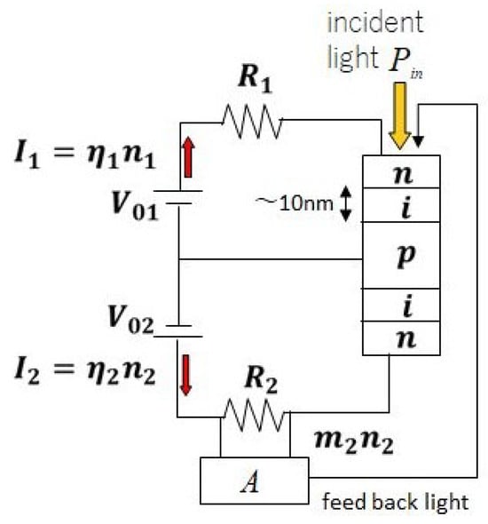
Figure 1.
Block diagram of pseudo-neuron device (DSEED) used in this study.
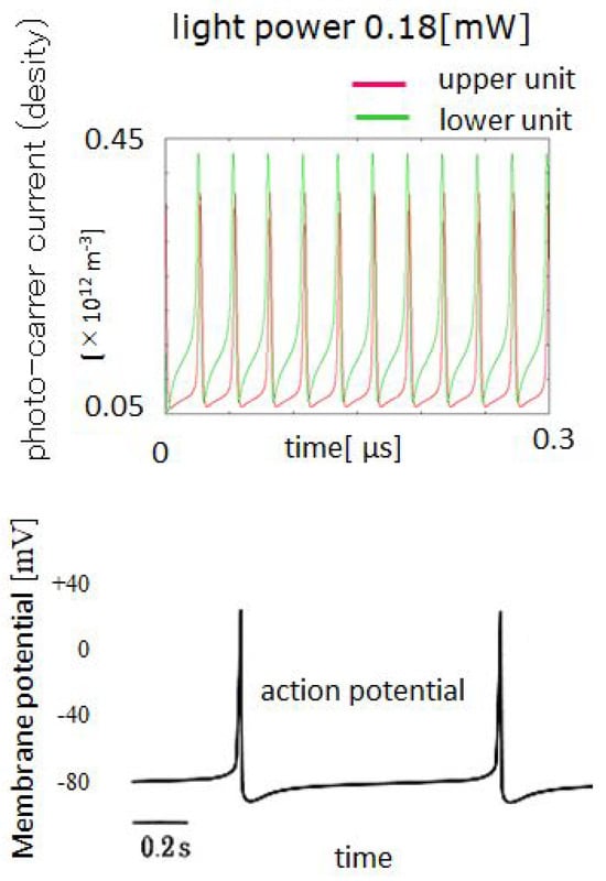
Figure 2.
Neuron-like nonlinear oscillation of the DSEED current [34,36] and the practically observed neuron action potential of firing [37].
For readers who are interested in more detailed analysis of DSEED operation, e.g., bifurcation diagram etc., the briefly summarized results taken from the previous works are shown in the Supplementary Materials.
Next, we introduce a diffusively coupled network for the DSEED, as shown in Figure 3. The equations of the photo-current in this network are as follows,
is the photo-carrier density in the network specified by in Figure 3, and represents the upper (lower) unit of the DSEED in Figure 1. is the term denoting the diffusive coupling of the carrier density between the upper (lower) units of the DSEED in the present network, which is transformed into diffusion terms at the two-dimensional continuum limit, as follows: . The descriptions of many parameters given in Equations (1) and (2) are omitted (see [36] for details). With an appropriate set of parameters and numerically solving them by the 4th-order Runge–Kutta method (time step = 10 ps), we are able to obtain chaotic operation as shown in Figure 3 and Figure 4, where notably, an example of chaos for a certain element is indicated. Additionally, the multiple-stable states are shown in Figure 4. Both are obtained by changing the incident light power. In a later section, what and how both network states are used to realize complex motion-control functions will be described.
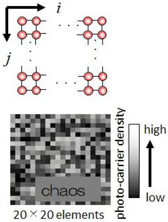
Figure 3.
The diffusively coupled network of the DSEED and a snapshot of the chaotic photo-carrier density of the DSEED network consisting of elements.
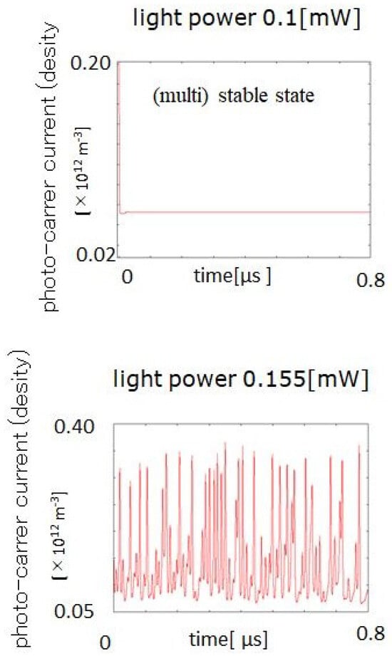
Figure 4.
Multiple−stable states and chaotic operations of the upper unit of a certain element in the network depending on the incident light power.
For readers who may be unsatisfied with the above short description and would feel that it provides “insufficient explanation of the chaotic NN analysis and behavior or insufficient providing of experimental details, such as the neural network architecture, parameter values”, let us show this information in more detail in the Supplementary Materials, in which a summarized description of the previous works e.g., [34], is written.
2.2. Roving Robot and Two-Dimensional Motion Control Via a Pseudo-Neuron Network (DSEED Network)
Given these multiple-stable and/or chaotic operations in the DSEED network, we have explored network applications in two-dimensional motion control in both computer experiments and practical hardware implementations involving roving robots; notably, successful implementations have been achieved in ill-posed contexts, e.g., solving two-dimensional mazes (labyrinth) [25,26]. Importantly, the ill-posed context considered here coincides with the typical definition of an ill-posed problem in mathematics, as follows;
- (1)
- The existence of a solution is not guaranteed in the sense that the structural information regarding the maze (labyrinth) is not given to the roving robot.
- (2)
- Even if a solution does exist, the uniqueness of the solution is not guaranteed in the sense that the route to the target is non-unique.
Therefore, the key point is realizing complex functions via simple rules, and the difficulty in solving this ill-posed problem is overcome through the use of chaotic dynamics. In our experiments, a coding concept in which high-dimensional () chaotic dynamics are reduced to two-dimensional motion is used, as shown in Figure 5.
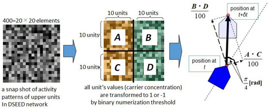
Figure 5.
Normalized inner products between two vectors in subspace ( and ) where the vector has components. The products are coded based on x- and y- directional motion increments, where the coordinates are fixed on the robot so that [(the front straight line)] is the x-axis and [] is the y-axis, as shown in the figure.
For readers who think that Figure 5 is too simple to understand “the design of the algorithms and the integration of chaos, and the implementation of robot motion”, a more detailed description taken from the previous works ([23,24,25,26]) is given in the Supplementary Materials.
The algorithm used to solve the maze is shown in Figure 6. The key idea is to switch the dynamics between multiple-stable states to provide forward motion and use chaotic dynamics to achieve chaotic motion depending on sensor information. In these experiments, the target emits sounds in all directions, and the roving robot is equipped with four microphones, each of which has a detectable range of sound within via directional sensing. Additionally, a sensor used to detect obstacles within a given movement increment is programmed to avoid collisions with the wall during motion to reach a target. Importantly, the algorithm applied is simple and can generate autonomous and adaptive robot behaviors; notably, it is not necessary to change this scheme based on different types of mazes to be solved. For example, the two successful cases for solving mazes are shown in Figure 7.
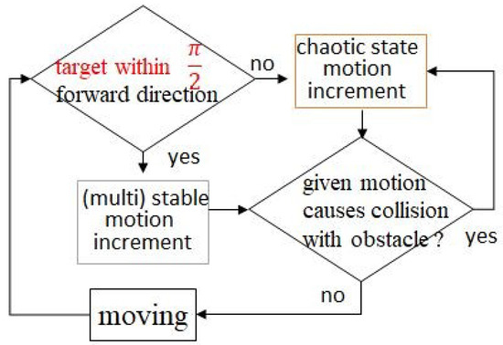
Figure 6.
A simple algorithm to solve the maze problem. It is not necessary to change this scheme based on the different types of mazes to be solved.
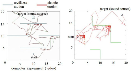
Figure 7.
Two successful cases of solving different mazes, with the goal of reaching a target. (Left) The red color indicates that the motion increments are calculated with the use of chaotic state, and the blue color denotes the use of stable state, respectively. (Right) Another successful case, where different colors are not used.
The hardware implementation of these computer experiments had been done in the previous works; notably, we constructed the experimental systems shown in Figure 8 and Figure 9, very briefly. Readers who do not have read our previous papers and are interested in “experimental setup, hardware configurations, and step-by-step procedures”, let us describe them in the Supplementary Materials as summarized forms taken from [23,24,25,26,34,35,36,38].
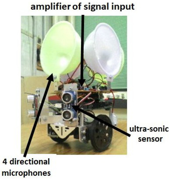
Figure 8.
Our roving robot modified from a Boe-Bot from Parallax Co. (Rocklin, CA, USA).
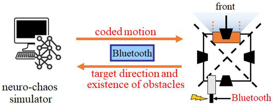
Figure 9.
Block diagram of our system. Notably, only the pseudo-neuron network is implemented on a PC because there is no “neuro-chip” available at present.
Two snapshots taken from the videos of successful cases are shown in Figure 10.
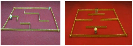
Figure 10.
Two successful cases solving different mazes with the same control system described in the text.
2.3. New Signal Devices for Practical Experiments with Two Roving Robots
In previous experiments in which one fixed target and one roving robot were used, the former was equipped with a device that emits sound in all directions, and the latter was equipped with a microphone device that detects sound from the target including directional uncertainty. In the present work, we investigate the interaction of two neural chaos via the behavioral interactions between two roving robots. Hence, both robots must be equipped for signal emission and signal detection. One device with a speaker and microphone was used already, and light-emitting diodes (LEDs) for signal emission and photo-transistors for detection were used for the other device (see Figure 11). For the chasing robot, 8 LEDs were attached, and for the fleeing robot, 4 photo-transistors were attached. The eight LEDs emit light in approximately all directions with isotropic intensity; on the other hand, the 4 photo-transistors detected light within the angle range in 4 directions, which means that detecting directional information includes uncertainty.

Figure 11.
New devices for signal emission and detection. For the chasing robot, 8 LEDs are used, and on the fleeing robot, 4 photo-transistors are used.
Let us note that, as mentioned in the previous section, more detailed information regarding step-by-step procedures of hardware implementation is briefly shown in the Supplementary Materials. This includes the previous works and new fabrications for this paper, in particular with respect to the 8-LED and photo-transistor systems, equipped on the tracing robot and target robot, respectively.
3. Results
3.1. Behavioral Interactions Between Two Roving Robots in a Maze
Supported by our successive works to develop techniques to make the roving robot described above, our new robot design was explored. First, computer experiments were performed. We prepared the two roving robots and, as noted in the introduction, established the following two ill-posed problems for the same maze (labyrinth);
- (1)
- each robot searches for the other robot
- (2)
- one robot attempted to catch the other, and the other fled to avoid capture.
To begin with, the first case is considered. The motion control algorithm proposed in a previous work was applied (see Figure 6); the fixed target (search target in a maze) in that work is replaced with searching robot in this work. The results of the computer experiments for the two cases are shown in Figure 12. Notably, in these two different maze cases, the motion generation algorithm is the same as that shown in Figure 6. These successful cases provide evidence that our control method is able to respond autonomously and adaptively in arbitrary established environments.
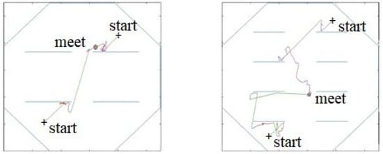
Figure 12.
Two successful cases of two robots search for each other. Note that the control system is not changed, but the two robots meet via successful route autonomously and adaptively determined in mazes with different structures.
Next, consider the second ill-posed problem in which one robot seeks the other to catch and the other attempts to avoid capturing. We emphasize that this problem is ill-posed based on the following conditions:
- (a)
- Both roving robots do not know the structure of the maze;
- (b)
- Both robots are equipped with sensors for target detection, but the detected information (e.g., direction of targets) includes large uncertainty such as within the angle range for the direction detection device (4 microphones and 4 photo-transistors in hardware-implemented experiments).
In such ill-posed cases, implementing typical operative processes on the basis of deterministic control methodology may result in issues regarding how uncertainty is treated in the information processing of signals and in determining feasible actions (motions). In contrast, the complex dynamic structure in the high-dimensional phase space of pseudo-neuron network that is coded for two-dimensional motion results in better routes for target searches with simple rules, such as those shown in Figure 6, which results in autonomous and adaptive behaviors for solving these ill-posed problems.
Therefore, in the second case, we design a new robot that flees from the chasing robot with the same chaos-based approach and control rules. The algorithms for the escaping robot and chasing robot are shown in Figure 13. The key idea for designing an escape robot is to set a new movement of forward rectilinear motion when the backward sensor detects the existence of the chasing robot within the angle range of the directional detection device.
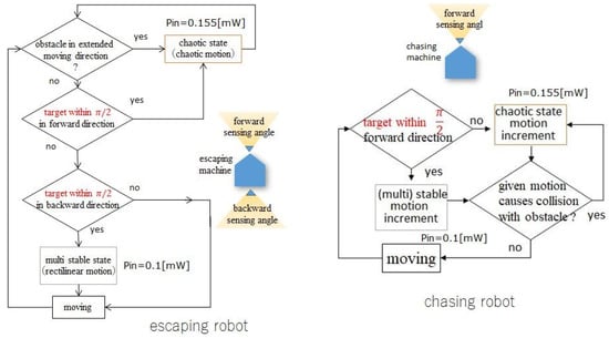
Figure 13.
The control algorithm for the escaping robot (left). The algorithm for the chasing robot (right) is the same as that in Figure 6.
On the basis of the algorithm described above to control a newly added roving robot that flees from capture robot, we present the results of computer experiments in Figure 14 and Figure 15. Notably, one roving robot seeks the other, and the other robot avoids capture. In Figure 14, all of the paths taken by both robots are shown to illustrate how the chasing robot avoids obstacles via chaotic motion and straightforwardly chases the target robot in a constrained free space. In Figure 15, the short paths traveled during chasing and fleeing are shown. Readers who are interested in watching videos of computer experiments can find them in the Supplementary Materials.
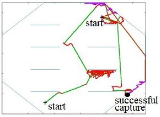
Figure 14.
An example of path recording in chasing and fleeing movement. Chasing corresponds to the green and red paths and fleeing, the brawn and purple paths, respectively.
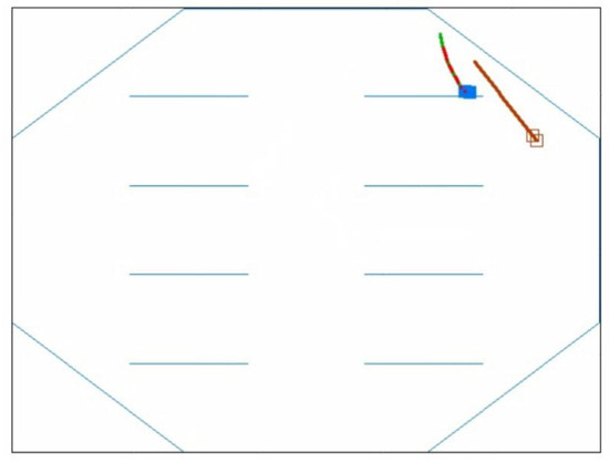
Figure 15.
Snap-shot during chasing and fleeing from a video of a movement path obtained during the computer experiments.
3.2. Hardware Implementation and Practical Experiments
Finally, hardware implementation was explored; notably, a signal-emitting device was added to the chasing robot, and a sensor device added to the escaping robot so that the latter was able to detect the existence of the former, as described in a previous section. A schematic diagram of the hardware-implementation and experiments is shown in Figure 16, and a snap-shot set of the initial state is shown at the bottom-right corner.
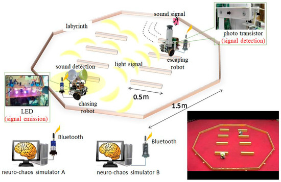
Figure 16.
Schematic diagram of our experimental system and a snap-shot taken from a successful case, shown at the bottom-right corner.
In this scenario, many successful cases are observed. An analysis of the results is given in Section 4. The seeking success rate when both roving robots seek each other was obtained for situations in which the pseudo-neuron network in the present case consisted of DSEEDs and the number of trials was 100. The other parameter values are given in the figure caption for Figure 17.
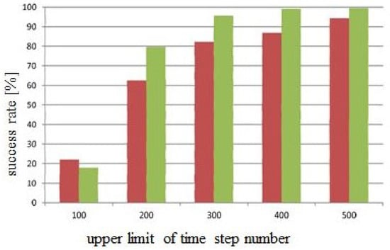
Figure 17.
The success rate of seeking (see Figure 12) over 100 trials; the results in brown and green correspond to 4 obstacles and 8 obstacles, respectively.
A more important and interesting problem is explored in the second case, in which one robot seeks the other robot to catch but the other flees to avoid capturing. An example is shown in Figure 14 and Figure 15. The capture success rate is visualized by changing three parameters: (i) the angle range for detecting the target in the chasing robot, (ii) the angle range for detecting the chasing robot forward and backward, and (iii) the velocity ratio between the two robots. Considering the computational time, we confine ourselves to three selections of the velocity ratio in the case (iii):
- (1)
- The velocity of both robots is equal;
- (2)
- The velocity of the escaping robot is the velocity of the chasing robot;
- (3)
- The velocity of the chasing robot is the velocity of the escaping robot.
Under these conditions, the success rate of capture is visualized as a function of the angle range of the detection sensors for the chasing robot and escaping robot. For the former, the sensor is attached to the front side, and for the latter, sensors are attached to both front and back sides. There is a wide selection of parameter values for these sensor devices, but consider a rather narrow rage. The results are shown in Figure 18.
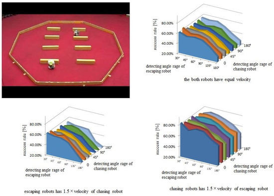
Figure 18.
Comparison of the success rate in the 3 cases in which the velocity ratio between the chasing robot and escaping robot varies.
4. Discussion
Here, we investigate and discuss the functional properties of two chaos models and the corresponding functional interactions introduced in this work by evaluating the meeting success rate, mainly with respect to computer experiments, as shown in the previous section.
First, in Figure 17, the case with 4 obstacles has the lower success rate, whereas the case with 8 obstacles has the higher success rate. The reason is presumably due to the configuration structure of the 8-obstacles case which has more free space in the central area than the 4-obstacles case does, as shown in Figure 12. It is plausible that the meeting success rate increases with increasing upper time step limit. The functional properties are sufficiently revealed in these figures, so further experiments concerning this case are not needed.
Second, as shown in Figure 18, one can observe several properties of the cases listed in the previous section; e.g., it is plausible that, in the case of a slower chasing velocity than an escaping robot, the success rate is globally lower than that in the other cases. Additionally, the success rate when the velocity of the chasing robot is faster than that of the escaping robot is globally greater than that in the case in which both velocities are equal.
As a further characteristic feature, there is a global tendency for the success rate to decrease with increasing detecting angle range. This is due to increasing uncertainty in detecting directional information with respect to target and/or chasing robots. However, considering these global tendencies, there are a few small hill-like extrema. These phenomena are interesting and interpreted as follows: although the directional information obtained by the sensor device includes uncertainty, optima detection angle range exists because too low of an angle range lead to dangerous unawareness of the chaser and too wide of a detection angle range can lead to overly ambiguous direction information concerning the existence of the chasing robot.
Finally, even when the velocity of the escaping robot is the velocity of the chasing robot, the success rate of capture is not as small as that shown in Figure 18. The reason is the existence of boundaries in this set context. If chasing and fleeing are executed in free space without boundaries, then the result could change substantially. In computer experiments and/or practical hardware-implemented experiments, we observe that the escaping robot generally stays near boundary walls and consequently captured by the chasing robot. Therefore, the existence of boundary walls is important in this context, and a case of free space for escaping a robot is an interesting task to explore in the future.
5. Conclusions
The concluding remarks of this work are as follows:
- (1)
- Neuroscience and brain-science are explored from the viewpoint of “what is the role of complex dynamics (chaotic dynamics) in biological systems such as the brain?”. Notably, several functional aspects of chaos are explored, particularly in the realization of “complex functions with simple rules” by introducing chaotic dynamics into control mechanisms in systems with finite but high degrees of freedom, which typically emerge in biological systems.
- (2)
- Both computer experiments and actual experiments with hardware-implemented robots, for instance, have revealed that chaos promotes various functional abilities.
- (3)
- In a practical sense, in this paper, we explore new experiments to investigate functional aspects of chaos via behavioral interactions in an ill-posed context, namely, two roving robots in a maze, seeking to catch each other or one chasing and the other fleeing, as observed in the survival activities of insects in natural environments. The successful results of both computer experiments and hardware-implemented experiments reveal that chaos dynamics can be used to guide autonomous and/or adaptive functions with simple rules.
- (4)
- Analyses of the results suggest that chaos dynamics in the high-dimensional phase space of a pseudo-neuron network are important for realizing advanced functions, but the present model and parameters cannot generate optimal dynamic structures. Thus, it is necessary to introduce a certain learning factor into these functions. This problem is similar to that in other functional applications of chaos in complex functions [17,38], and this topic will be further explored in our future work.
Supplementary Materials
The supporting information can be watched at https://www.mdpi.com/article/10.3390/dynamics5030032/s1
Author Contributions
Conceptualization, S.N., Y.Y., and I.T.; methodology, S.N. and N.M.; software, S.N. and N.M.; validation, S.N.; formal analysis, S.N. and N.M.; investigation, S.N., Y.Y., and I.T.; resources, S.N., Y.Y., and I.T.; supervision, S.N., Y.Y., and I.T.; project administration, S.N.; funding acquisition, S.N. and Y.Y. All authors have read and agreed to the published version of the manuscript.
Funding
This research was funded by JSPS KAKENHI Grant Number 23K11256, and the contribution of S.N. to this research was partly funded by JSPS KAKENHI Grant Number 20K12002 and the Cooperative Research Program of “Network Joint Research Center for Materials and Devices”. Additionally, one of the authors, I.T., was partially supported by internal funds from Sapporo City University.
Data Availability Statement
The original contributions presented in this study are included in the article/Supplementary Material. Further inquiries can be directed to the corresponding author.
Acknowledgments
One of the authors, S.N., would like to acknowledge Yasunori Tokuda for his valuable discussion with respect to the DSEED. Additionally, S.N. would like to thank Yoshitomo Goto and Tomoyuki Nagaya for their interesting discussions regarding the chaotic pattern dynamics of the DSEED network.
Conflicts of Interest
The authors declare no conflict of interest.
References
- Freeman, W.; Quiroga, Q.R. Imaging Brain Function with EEG: Advanced Temporal and Spatial Analysis of Electroencephalographic Signals; Springer: Berlin/Heidelberg, Germany, 2014. [Google Scholar] [CrossRef]
- Haken, H. Principles of Brain Functioning; Springer: Berlin/Heidelberg, Germany, 1996; Volume 67. [Google Scholar]
- Kay, L.M.; Lancaster, L.R.; Freeman, W.J. Reafference and attractors in the olfactory system during odor recognition. Int. J. Neural Syst. 1996, 4, 489–495. [Google Scholar] [CrossRef]
- Hebb, D.O. The Organization of Behavior; A Neuropsychological Theory; Wiley: Oxford, UK, 1949. [Google Scholar]
- Amari, S. Neural Theory of Association and Concept-Formation. Biol. Cybern. 1977, 26, 175–185. [Google Scholar] [CrossRef]
- Hopfield, J.J. Neural networks and physical systems with emergent collective computational abilities. Proc. Natl. Acad. Sci. USA 1982, 258, 243–245. [Google Scholar] [CrossRef]
- Tsukada, M.; Pan, X. The spatiotemporal learning rule and its efficiency in separating spatiotemporal patterns. Biol. Cybern. 2005, 92, 139–146. [Google Scholar] [CrossRef]
- Hassabis, D.; Kumaran, D.; Summerfield, C.; Botvinick, M. Neuroscience-inspired artificial intelligence. Neuron 2017, 95, 245–258. [Google Scholar] [CrossRef]
- Huber, F.; Thorson, J. Cricket Auditory Communication. Sci. Am. 1985, 253, 60–73. [Google Scholar] [CrossRef]
- Nicolelis, M.A.L. Actions from thoughts. Nature 2001, 409, 403–407. [Google Scholar] [CrossRef] [PubMed]
- Hayashi, H.; Ishizuka, S.; Ohta, M.; Hirakawa, K. Chaotic behavior in the Onchidium giant neuron under sinusoidal stimulation. Phys. Lett. A 1982, 88, 435–438. [Google Scholar] [CrossRef]
- A Babloyantz, A.; Destexhe, A. Low-dimensional chaos in an instance of epilepsy. Proc. Natl. Acad. Sci. USA 1986, 83, 3513–3517. [Google Scholar] [CrossRef]
- Skarda, C.A.; Freeman, W.J. How brains make chaos in order to make sense of the world. Behav. Brain Sci. 1987, 10, 161–173. [Google Scholar] [CrossRef]
- Sompolinsky, H.; Crisanti, A.; Sommers, H.J. Chaos in Random Neural Networks. Phys. Rev. Lett. 1988, 61, 259–262. [Google Scholar] [CrossRef] [PubMed]
- Aihara, K.; Takabe, T.; Toyoda, M. Chaotic neural networks. Phys Lett. A 1990, 114, 333–340. [Google Scholar] [CrossRef]
- Fujii, H.; Itoh, H.; Ichinose, N.; Tsukada, M. Dynamical cell assembly hypothesis—Theoretical possibility of spacio-temporal coding in the cortex. Neural Netw. 2003, 9, 1303–1350. [Google Scholar]
- Tsuda, I. Toward an interpretation of dynamic neural activity in terms of chaotic dynamical systems. Behav. Brain Sci. 2001, 24, 793–847. [Google Scholar] [CrossRef]
- Kaneko, K.; Tsuda, I. Chaotic itinerancy. Chaos Interdiscip. J. Nonlinear Sci. 2003, 13, 926–936. [Google Scholar] [CrossRef] [PubMed]
- Bertschinger, N.; Natschläger, T. Real-time computation at the edge of chaos in recurrent neural networks. Neural Comput. 2004, 16, 1413–1436. [Google Scholar] [CrossRef]
- Robert, K.; Walter, W. Cognitive Phase Transitions in the Cerebral Cortex-Enhancing the Neuron Doctrine by Modeling Neural Fields; Springer: Berlin/Heidelberg, Germany, 2015. [Google Scholar]
- Tokuda, K.; Fujiwara, N.; Sudo, A.; Katori, Y. Chaos may enhance expressivity in cerebellar granular layer. Neural Netw. 2021, 136, 72–86. [Google Scholar] [CrossRef]
- Nara, S.; Davis, P. Learning feature constraints in a chaotic neural memory. Phys. Rev. E 1997, 55, 826–830. [Google Scholar] [CrossRef]
- Suemitsu, Y.; Nara, S. A Solution for Two-dimensional Mazes with Use of Chaotic Dynamics in a Recurrent Neural Network Model. Neural Comput. 2004, 16, 1943–1957. [Google Scholar] [CrossRef]
- Yoshida, H.; Kurata, S.; Li, Y.; Nara, S. Chaotic neural network applied to two-dimensional motion control. Cogn. Neurodyn. 2010, 4, 69–80. [Google Scholar] [CrossRef][Green Version]
- Li, Y.; Kurata, S.; Morita, S.; Shimizu, S.; Munetaka, D.; Nara, S. Application of chaotic dynamics in a recurrent neural network to control: Hardware implementation into a novel autonomous roving robot. Biol. Cybern. 2008, 99, 185–196. [Google Scholar] [CrossRef] [PubMed]
- Yoshinaka, R.; Kawashima, M.; Takamura, Y.; Yamaguchi, H.; Miyahara, N.; Nabeta, K.; Li, Y.; Nara, S. Adaptive Control of Robot Systems with Simple Rules Using Chaotic Dynamics in Quasi-layered Recurrent Neural Networks. In Computational Intelligence; Madani, K., Dourado Correia, A., Rosa, A., Filipe, J., Eds.; Springer: Berlin/Heidelberg, Germany, 2012; Volume 399, pp. 287–305. [Google Scholar]
- Nakamura, Y.; Sekiguchi, A. The chaotic mobile robot. IEEE Trans. Robot. Autom. 2001, 17, 898–904. [Google Scholar] [CrossRef]
- Sompolinsky, H.; Kanter, I. Temporal Association in Asymmetric Neural Networks. Phys. Rev. Lett. 1986, 57, 2861–2864. [Google Scholar] [CrossRef]
- Amit, D.J. Neural networks counting chimes. Proc. Natl. Acad. Sci. USA 1987, 85, 2141–2145. [Google Scholar] [CrossRef]
- Haken, H. Neural and Synergetic Computers; Springer: Berlin/Heidelberg, Germany, 1990; Volume 42. [Google Scholar]
- Anderson, J.A.; Rosenfeld, E. Neurocomputing 1: Foundations of Research; MIT Press: Cambridge, MA, USA, 1988. [Google Scholar]
- Anderson, J.A.; Pellionisz, A.; Rosenfeld, E. Neurocomputing 2: Directions for Research; MIT Press: Cambridge, MA, USA, 1990. [Google Scholar]
- Northmore, D.; Elias, J. Pulsed Neural Networks; Maass, W., Bishop, C.M., Eds.; MIT Press: Cambridge, MA, USA, 1999; pp. 135–156. [Google Scholar]
- Ohkawa, T.; Yamamoto, Y.; Nagaya, T.; Nara, S. Dynamic behaviors in coupled self-electrooptic effect devices. Appl. Phys. Lett. 2005, 86, 111107. [Google Scholar] [CrossRef]
- Tokuda, Y.; Abe, Y.; Kanamoto, K.; Tsukada, N. Complex multistable responses of serially connected optical bistable devices. Appl. Phys. Lett. 1991, 59, 1016–1018. [Google Scholar] [CrossRef]
- Yamamoto, T.; Ohkawa, Y.; Kitamoto, T.; Nagaya, T.; Nara, S. Bifurcation phenomena in coupled dynamic self-electro-optic-effect devices. Int. J. Bifurc. Chaos 2006, 16, 3717–3725. [Google Scholar] [CrossRef]
- Hindmarsh, J.; Rose, R.M. A Model of the Nerve Impulse Using Two First-Order Differential Equations. Nature 1982, 296, 162–164. [Google Scholar] [CrossRef] [PubMed]
- Kuwada, S.; Aota, T.; Uehara, K.; Nara, S. Application of chaos in a recurrent neural network to control in ill-posed problems: A novel autonomous robot arm. Biol. Cybern. 2018, 112, 495–508. [Google Scholar] [CrossRef] [PubMed]
Disclaimer/Publisher’s Note: The statements, opinions and data contained in all publications are solely those of the individual author(s) and contributor(s) and not of MDPI and/or the editor(s). MDPI and/or the editor(s) disclaim responsibility for any injury to people or property resulting from any ideas, methods, instructions or products referred to in the content. |
© 2025 by the authors. Licensee MDPI, Basel, Switzerland. This article is an open access article distributed under the terms and conditions of the Creative Commons Attribution (CC BY) license (https://creativecommons.org/licenses/by/4.0/).