Abstract
Many physical processes can be described via nonlinear second-order ordinary differential equations and so, exact solutions to these equations are of interest as, aside from their accuracy, they may reveal beforehand key properties of the system’s response. This work presents a method for computing exact solutions of second-order nonlinear autonomous undamped ordinary differential equations. The solutions are divided into nine cases, each depending on the initial conditions and the system’s first integral. The exact solutions are constructed via a suitable parametrization of the unknown function into a class of functions capable of representing its behavior. The solution is shown to exist and be well-defined in all cases for a general nonlinear form of the differential equation. Practical properties of the solution, such as its period, time to reach an extreme value or long-term behavior, are obtained without the need of computing the solution in advance. Illustrative examples considering different types of nonlinearity present in classical physical systems are used to further validate the obtained exact solutions.
1. Introduction
The present work is concerned with the exact solutions of second-order nonlinear autonomous undamped ordinary differential equations. Many systems in nature can be modeled using these types of differential equations and so, their solutions are of immediate interest. Examples of applications include the vibrations of nonlinear mechanical systems [1], the oscillations of current or voltage in a nonlinear electric circuit [2] and the orbits of a two-body gravitational systems [3], among others.
Many researchers have investigated exact solutions for nonlinear ordinary and partial differential equations. Zhang [4] constructed exact polynomial solutions of linear second-order differential equations. Ghaemi et al. [5] studied the Hyers–Ulam stability of exact second-order linear differential equations. Lenci [1] developed exact solutions for coupled Duffing oscillators. Liao and Tan [6] discussed a general approach to obtain series solutions of nonlinear differential equations. Bartha et al. [7] computed the stable periodic orbits for the Mackey–Glass equation. Burmasheva and Prosviryakov [8] developed exact solutions to Navier–Stokes equations describing a gradient non-uniform unidirectional vertical vortex fluid flow. Carravetta [9] developed a power series solution for nonlinear ordinary differential equations having a quadratic form. Liu and Geng [10] obtained exact solutions to the systems of carbon nanotubes conveying fluid via symmetry reductions. Korman and Li [11] studied the multiplicity of positive solutions for differential equations with concave–convex and convex–concave nonlinear behavior. Cheviakov [12] developed exact closed-form solutions of a fully nonlinear asymptotic two-fluid model. Tur et al. [13] studied vortex structures with complex points singularities in two-dimensional Euler equations. Volpert et al. [14] developed exact solutions in front propagation problems with superdiffusion. MacNeil et al. [15] developed exact and approximate solutions for optical solitary waves in nematic liquid crystals. Zubarev and Zubareva [16] developed exact solutions for the shape of a two-dimensional conducting liquid drop in a non-uniform electric field. Santana et al. [17] developed closed-form solutions for the symmetric nonlinear free oscillations of pyramidal trusses.
The main idea behind the method developed in the present work consists of identifying the key properties of the solution and, from them, building a suitable parametrization that encapsulates the solution’s behavior. The parametrization of the unknown function into an auxiliary function is then proven to be valid. The invertible function connecting the auxiliary function and the independent parameter is obtained, leading to the exact solution of the problem. Multiple reliable numerical methods for computing the solution of the type of differential equations considered in the present work exist in the literature [18,19]. Also, exact solutions for particular second-order ordinary differential equations are available [4,17]. However, when dealing with the general exact solution of such problems, there is a gap in knowledge that the present contribution aims to fill. The main originalities of the present contribution are listed below:
- •
- Exact solution of general second-order nonlinear autonomous undamped differential equations;
- •
- Identification of the system class from the initial conditions;
- •
- Identification of the system’s general properties (e.g., period, time to reach extremes, long term behavior) before computing the solution.
The manuscript is organized as follows. The type of ordinary differential equation considered in the present work is discussed in Section 2. The solutions are divided into nine cases, depending on the ability of the system to absorb the energy provided by the initial conditions. The exact solutions are developed in Section 2.2.1, Section 2.2.2, Section 2.2.3, Section 2.2.4, Section 2.2.5, Section 2.2.6, Section 2.2.7, Section 2.2.8 and Section 2.2.9. The algorithm allowing for the implementation of the proposed exact solution is discussed in Section 3. Multiple examples of classical nonlinear mechanical systems are used in Section 4 to validate the developed exact solution. Finally, some conclusions and suggestions for further developments are presented in Section 5.
2. Exact Solutions
In this section, the initial value problem (IVP) of interest is defined, and some useful properties of the solution are discussed. The goal of the present work is to compute a function satisfying the following second-order autonomous nonlinear ordinary differential equation (ODE) for a given function :
Throughout the paper, represents the set of functions that are k times continuously differentiable. The function x must also satisfy the following initial conditions for given :
The second-order nonlinear ODE in Equation (1) can be classified as undamped since the function does not depend directly on the rate of change . It can also be classified as autonomous since the function does not depend directly on the independent parameter t, but only via the dependent unknown function . A function x that satisfies Equation (1) together with the initial conditions in Equations (2) and (3) is said to be a solution of the initial value problem (IVP). The uniqueness of the solution is not investigated in the present contribution but can be studied via the classical Cauchy–Lipschitz theorem [20]. Also, under the condition of , a solution is shown to always exist. Let be defined as follows:
When the differential equation in Equation (1) is used to model a physical system, the functions f and U represent the internal force and the internal energy of the system, respectively. Multiplying Equation (1) by and integrating over the interval provides
The principle of the method developed in the present work is to set the solution x as a composition of two functions and , that is, . As it will be shown, the function z captures the qualitative behavior of the solution (Section 2.2), while the function h maps the parameter t from the domain of x to the domain of z (Section 2.1). The following conditions are imposed over the function z:
2.1. Parameter Mapping
For a fixed function z and a fixed initial parameter , the initial condition allows setting . Also, from the condition in Equation (8), the function in Equation (9) is well-defined:
Replacing the composition in Equation (5) and imposing that h must be strictly increasing, thus we have
The condition of h being strictly increasing could be replaced by h being strictly decreasing without any loss of generality. It is important, however, that h is strictly monotonic, so that a one-to-one relation between the domains of x and z can be later established. The equation above represents a first-order nonlinear ODE on h with initial condition . Since g is strictly positive, an implicit solution to this equation can be obtained as follows:
The relation in Equation (11) provides a unique value of and, therefore, the function is well-defined and surjective. The implicit character of Equation (11) is reminiscent of the nonlinearity of Equation (1) and is similar to the one appearing in the Jacobi amplitude function, used to solve the nonlinear pendulum ODE [21].
Theorem 1.
2.2. Qualitative Behavior of the Solution
In this section, classes are identified providing functions z that represent the qualitative behavior of the solution and satisfy the conditions in Equations (6)–(8). Let the limit sets and be defined as follows:
From the definitions in Equations (22) and (23), if, and only if, . Also, if, and only if, and , otherwise . When , we set and, when , we set . The following theorem shows how the signs of and are restrained.
Theorem 2.
If , then . Also, if , then .
Proof.
Suppose, by way of contradiction, that . From the definition of in Equation (22), . Since U is continuous, . As , . If or and , then and , which contradicts the fact that . If and , then . Since in the interval and in the interval , there must exist such that , which once more contradicts the fact that .
The proof for follows the same path. Suppose, by way of contradiction, that . From the definition of in Equation (23), . Since U is continuous, . As , . If or and , then and , which contradicts the fact that . If and , then . Since in the interval and in the interval , there must exist such that , which once more contradicts the fact that . □
From the definitions in Equations (22) and (23) and the result in Theorem 2, the IVP is related to one of the nine cases presented in Table 1.

Table 1.
Nine possible cases of the IVP.
As it will be shown, each of these cases have a particular behavior that motivates the construction of the developed exact solution. More precisely, a class of functions having a certain set of properties is defined for the nth case. An arbitrary function in this class does not represent an exact solution to the IVP, but encapsulates the general behavior of the solution. The link between the function and the actual solution of the IVP is then established via the mapping function , representing the evolution of the parametrization.
Due to the criteria of and/or in cases 5 to 9, the solution is sensible to the initial conditions in these cases, given that any variation on them would push the solution method to one of the other cases. Therefore, exact solutions are of particular interest since the numerical errors present in approximate methods can easily misrepresent the behavior of the solution, as will be shown in Section 4.
2.2.1. Case 1
Case 1 is described by , Notice that in this case, since would imply . When the IVP is used to model a physical system, the internal energy is never able to fully absorb the energy level and, hence, the system continues to evolve without bounds. These arguments motivate the following conditions over the function :
As an example of such a function, one has
For the example function z in Equation (27), a unique satisfying Equation (7) can be obtained as
Theorem 3.
Under the conditions of case 1, a function that satisfies Equations (24)–(26) is bijective and also satisfies Equations (6)–(8).
Proof.
Recalling that , Equation (24) implies that . Also, since , . Therefore, the condition in Equation (6) is identically satisfied. The condition in Equation (24) implies that z is strictly monotonic and, therefore, injective. The limits in equations Equations (25) and (26) then imply that z is neither lower nor upper bounded. The continuity of z then implies its surjectivity and so . From Equation (24), and so, the condition in Equation (7) is satisfied. Finally, since , and , the condition in Equation (8) is also satisfied. □
2.2.2. Case 2
Case 2 is described by , and . When the IVP is used to model a physical system, its internal energy is able to fully absorb the energy level only at one point to the right of the initial condition and then bounces to negative infinity. These arguments motivate the following conditions over the function :
As an example of such a function, one has
For the example function z in Equation (31), a unique satisfying Equation (7) can be obtained as follows:
Theorem 4.
Under the conditions of case 2, a function that satisfies Equations (29) and (30) is surjective and also satisfies Equations (6)–(8).
Proof.
The co-domain and continuity of z imply that , since is a local (and global) maximum. Therefore, Equation (29) implies that z is strictly increasing in and strictly decreasing in . Hence, or imply . From the definition of case 2, implies . The condition in Equation (6) is then satisfied.
Since does not approach 0 as p tends to , z is not lower bounded neither in nor in . Therefore, the restrictions and are bijective. The following satisfies then the conditions in Equation (7):
Applying L’Hôpital’s rule, the limit as can be determined as
The condition in Equation (8) is then also satisfied. □
From Equation (30), implies . The time to reach the maximum value can then be determined from Equation (11) as follows:
2.2.3. Case 3
Case 3 is described by , and . When the IVP is used to model a physical system, its internal energy is able to fully absorb the energy level only at one point to the left of the initial condition and then bounces to positive infinity. It is worth noting that this case corresponds to the symmetric inverse of case 2 in Section 2.2.2 and, hence, the solutions have similar behavior. These arguments motivate the following conditions over the function :
As an example of such a function, one has
For the example function z in Equation (38), a unique satisfying Equation (7) can be obtained as follows:
Theorem 5.
Under the conditions of case 3, a function that satisfies Equations (36) and (37) is surjective and also satisfies Equations (6)–(8).
Proof.
The co-domain and continuity of z imply that , since is a local (and global) minimum. Therefore, Equation (36) implies that z is strictly decreasing in and strictly increasing in . Hence, or imply . From the definition of case 3, implies . The condition in Equation (6) is then satisfied.
Since does not approach 0 as p tends to , z is not upper bounded neither in nor in . Therefore, the restrictions and are bijective. The following satisfies then the conditions in Equation (7):
Applying L’Hôpital’s rule, the limit as can be determined as follows:
The condition in Equation (8) is then also satisfied. □
From Equation (37), implies . The time to reach the minimum value can then be determined from Equation (11) as follows:
2.2.4. Case 4
Case 4 is described by , , and . The solution’s behavior is lower and upper bounded. When the IVP is used to model a physical system, its internal energy is able to fully absorb the energy level at points to the left and right of the initial condition and, hence, bounces between them. These arguments motivate the following conditions over the function :
In Equations (44)–(46), is the period of z. As an example of such a function, one has
For the example function z in Equation (31), a satisfying Equation (7) can be obtained as follows:
Theorem 6.
Under the conditions of case 4, a function that satisfies Equations (43)–(47) also satisfies Equations (6)–(8).
Proof.
Recalling Equation (46), implies or , with . From the definition of case 4, implies or . Equations (44) and (45) then imply that or , with . The condition in Equation (6) is then satisfied.
It is assumed, without loss of generality, that . From Equation (46) and recalling that , in and in , the restrictions and are then bijective. The following satisfies then the conditions in Equation (7):
The limit as , with , is determined via L’Hôpital’s rule, taking into account that (Equation (47)):
The limit as , with , is determined via L’Hôpital’s rule, taking into account that (Equation (47)):
The condition in Equation (8) is then also satisfied. □
The periodicity of z implies the periodicity of and g. From Equation (11), the following relation can then be obtained:
The periodicity of the solution x, with period , can then be shown:
2.2.5. Case 5
Case 5 is described by , and . Notice that in this case, since would imply . When the IVP is used to model a physical system, its internal energy is never able to fully absorb the energy level, but tends to/from a point (located to the right of the initial condition) and bounces from/to infinity. These arguments motivate the following conditions over the function :
As an example of such a function, one has
For the example function z in Equation (57), a unique satisfying Equation (7) can be obtained as follows:
Theorem 7.
Under the conditions of case 5, a function that satisfies Equations (55) and (56) is bijective and also satisfies Equations (6)–(8).
Proof.
The limit in Equation (56) implies that as . Therefore, from Equation (55), and z is injective. Recalling the definition of case 5 and the co-domain of z, and the condition in Equation (6) is identically satisfied. Equation (55) implies that does not approach 0 as and hence, z is not lower bounded. The continuity of z then implies its surjectivity and so the condition in Equation (7) is satisfied. Finally, since , and , the condition in Equation (8) is also satisfied. □
2.2.6. Case 6
Case 6 is described by , and . Notice that in this case, since would imply . When the IVP is used to model a physical system, its internal energy is never able to fully absorb the energy level, but tends to/from a point (located to the left of the initial condition) and bounces from/to infinity. It is worth noting that this case corresponds to the symmetric inverse of case 5 in Section 2.2.5 and, hence, the solutions have a similar behavior. These arguments motivate the following conditions over the function :
As an example of such a function, one has
For the example function z in Equation (61), a unique satisfying Equation (7) can be obtained as follows:
Theorem 8.
Under the conditions of case 6, a function that satisfies Equations (59) and (60) is bijective and also satisfies Equations (6)–(8).
Proof.
The limit in Equation (60) implies that as . Therefore, from Equation (55), and z is injective. Recalling the definition of case 5 and the co-domain of z, and the condition in Equation (6) is identically satisfied. Equation (55) implies that does not approach 0 as and hence, z is not lower bounded. The continuity of z then implies its surjectivity and so the condition in Equation (7) is satisfied. Finally, since , and , the condition in Equation (8) is also satisfied. □
2.2.7. Case 7
Case 7 is described by , , and . When the IVP is used to model a physical system, its internal energy is able to fully absorb the energy level at a point to the left of the initial condition and tends from and to a point to the right of the initial condition that is also able to fully absorb the energy level. These arguments motivate the following conditions over the function :
As an example of such a function, one has
For the example function z in Equation (67), a unique satisfying Equation (7) can be obtained as follows:
Theorem 9.
Under the conditions of case 7, a function that satisfies Equations (63)–(66) is surjective and also satisfies Equations (6)–(8).
Proof.
From Equations (63)–(65) and the co-domain of z, implies and in and in . Recalling the definition of case 7, implies , implying . The condition in Equation (6) is then satisfied.
The limit conditions in Equations (63) and (64) and the continuity of z imply its surjectivity in and in . Hence, the restrictions and are bijective. The following satisfies then the conditions in Equation (7):
The limit as is determined via L’Hôpital’s rule:
The condition in Equation (8) is then also satisfied. □
From Equation (65), implies . The time to reach the minimum value can then be determined from Equation (11) as follows:
2.2.8. Case 8
Case 8 is described by , , and . When the IVP is used to model a physical system, its internal energy is able to fully absorb the energy level at a point to the right of the initial condition and tends from and to a point to the left of the initial condition that is also able to fully absorb the energy level. It is worth noting that this case corresponds to the symmetric inverse of case 7 in Section 2.2.7 and, hence, the solution have a similar behavior. These arguments motivate the following conditions over the function :
As an example of such a function, one has
For the example function z in Equation (76), a unique satisfying Equation (7) can be obtained as follows:
Theorem 10.
Under the conditions of case 8, a function that satisfies Equations (72)–(75) is surjective and also satisfies Equations (6)–(8).
Proof.
From Equations (72)–(74) and the co-domain of z, implies and in and in . Recalling the definition of case 8, implies , implying . The condition in Equation (6) is then satisfied.
The limit conditions in Equations (72) and (73) and the continuity of z imply its surjectivity in and in . Hence, the restrictions and are bijective. The following satisfies then the conditions in Equation (7):
The limit as is determined via L’Hôpital’s rule:
The condition in Equation (8) is then also satisfied. □
From Equation (74), implies . The time to reach the maximum value can then be determined from Equation (11) as follows:
2.2.9. Case 9
Case 9 is described by , , and . When the IVP is used to model a physical system, its internal energy is never able to fully absorb the energy level, but tends from and to points to the left and right to the initial condition that are able to fully absorb the energy level. These arguments motivate the following conditions over the function :
As an example of such a function, one has
For the example function z in Equation (84), a unique satisfying Equation (7) can be obtained as follows:
Theorem 11.
Under the conditions of case 9, a function that satisfies Equations (81)–(83) also satisfies Equations (6)–(8).
Proof.
Recalling that , Equation (83) implies that . From the definition of case 9 and the co-domain of z, . Therefore, the condition in Equation (6) is identically satisfied. The limits in Equations (81) and (82) and the continuity of z imply its continuity. Hence, . From Equation (83), and so, the condition in Equation (7) is satisfied. Finally, since , and , the condition in Equation (8) is also satisfied. □
3. Algorithm
In this section, an algorithm to compute the exact solution of the IVP is described. The algorithm takes as inputs the function , the initial condition parameters , and and the current parameter t and outputs the exact solution .
The first step consists of determining the IVP type (Table 1), which is determined by checking the existence of points to left () and to the right () of such that . Unfortunately, there are not analytical methods to determine the existence of roots of a general function and so, a numerical approach is used. More precisely, the algorithm takes as additional input the boundaries ( and ) and divides the intervals and in a uniform mesh. Next, the bisection method is used to determine if a point of exists in each sub-interval of and if a point of exists in each sub-interval of . Taking the direction starting with in each case ensures that, if the points and/or are found, they represent the maximum and minimum of and , respectively. The bisection method is also used in each of these sub-intervals to search for points x with . If this later condition is satisfied, the condition is checked and the special points of cases 5 to 9 can be computed.
The use of the bisection method assumes that the search function is monotonic in each of the sub-intervals. This hypothesis can be assured by controlling the size of the uniform mesh. It is worthy noting that, for specific functions U or f analytical tools can often be applied to determine the existence of the roots, excluding the need for numerical root-finding methods.
Once the type of the IVP is determined, a function z respecting the conditions in Equations (6)–(8) can be chosen. In the present work, the example functions z and initial parameters in Section 2.2.1, Section 2.2.2, Section 2.2.3, Section 2.2.4, Section 2.2.5, Section 2.2.6, Section 2.2.7, Section 2.2.8 and Section 2.2.9 are used; however, any function in the given class could be adopted. For a fixed z, the value of can be determined from Equation (11) and the exact solution can be computed as . Due to the careful definition of the function g in Equation (9), the solution can be computed without any singularities or numerical instabilities. Moreover, since the function h is strictly monotonic, the implicit relation in Equation (11) can always be solved to an arbitrary level of precision. It is worth noting that, the use of a numerical approach is used to determine the type of the IVP and compute the mapping for a given parameter t, does not spoil the exactness of the solution since the latter can be computed to an arbitrary level of precision and no approximation of the ODE is employed, yielding a solution that is independent of the time step size.
4. Examples and Validation
In this section, IVPs used to model well-known nonlinear mechanical systems are used to showcase the accuracy and capacities of the developed method. The explicit fourth-order Runge–Kutta [22] and implicit Newmark [18] numerical methods are used for comparison, where a converged time step is adopted. Special initial conditions, close or equal to critical points, are used to highlight the exactness of the developed solution even when numerical methods fail due to drift errors.
4.1. Nonlinear Pendulum
The first example studied in this section is the nonlinear pendulum (Figure 1). The pendulum consists of a point mass m attached to a rigid string with length L. The point mass is subjected to the tension force of the string and the action of gravity with acceleration g. The equation of motion of the system can be written as follows [23,24]:
with initial conditions
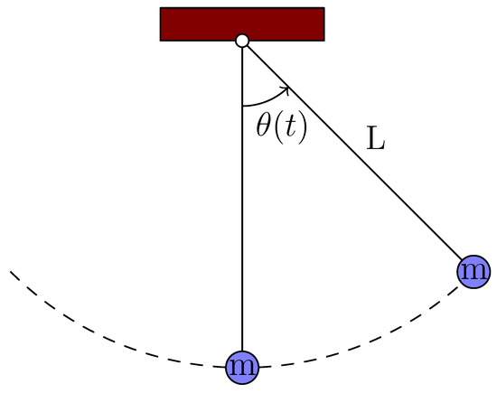
Figure 1.
Nonlinear pendulum.
The force f and energy U functions of the system can then be obtained as follows:
The internal energy function U of the nonlinear pendulum is shown in Figure 2. Three initial conditions, corresponding to cases 1, 4 and 9 from Section 2.2.1, Section 2.2.4 and Section 2.2.9, respectively, are considered in order to highlight the capabilities of the developed exact solution in extreme cases. Considering the downward initial position , the critical initial velocity that brings the pendulum to the upward position () can be obtained from Equation (90):
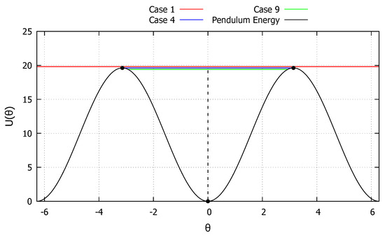
Figure 2.
Internal energy of the nonlinear pendulum.
The first initial condition studied is taken as and , corresponding to an energy level just above the critical one and is represented by the red line in Figure 2. The system is then never capable of fully absorbing the energy level and a certain amount of kinetic energy is always present, corresponding to the behavior described in Section 2.2.1. The results obtained with the developed exact solution, the Newmark and RK4 methods, are shown in Figure 3. As can be observed, the developed exact solution shows a good agreement with the numerical methods and represents well the general monotonic behavior.
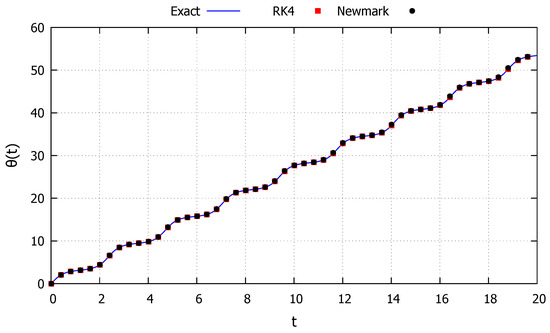
Figure 3.
Nonlinear pendulum: Case 1.
The second initial condition studied is taken as and , corresponding to an energy level just below the critical one and is represented by the blue line in Figure 2. The system is then capable of fully absorbing the energy level at points to the left and to the right of the initial position, corresponding to the behavior described in the Section 2.2.4. The results obtained with the developed exact solution, the Newmark and RK4 methods are shown in Figure 4. As can be observed, the developed exact solution shows a good agreement with the numerical methods and represents well the general oscillatory behavior. It is worth noting that, while both numerical methods starts to diverge from the periodic behavior, the exact solution retains this key property. Moreover, the dashed black lines in Figure 4 represent the period s, calculated via Equation (54), showcasing its accuracy.
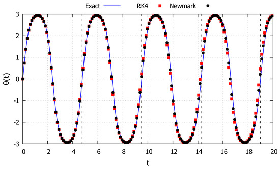
Figure 4.
Nonlinear pendulum: Case 4.
Although the two numerical methods appear to drift by the same amount, in Figure 4 the red (RK4) and black (Newmark) points vary for the same values of the parameter t, and for these points start to visibly differ from one another, indicating loss of accuracy of the numerical methods. Moreover, the accuracy of the exact solution can be verified by the dash lines indicating the period of the response. Since the energy provided by the initial conditions in this case is smaller than the critical one, the solution must always be periodic. Until the second dashed line (), all solutions have approximately the same period. However, after this point, the solutions from the two numerical methods (via drift errors) have a smaller period, while the response from the exact solution maintain the original period.
For a null initial velocity (), the response of the system is always periodic, falling in case 4 of Section 2.2.4. The period of the response can than be calculated as a function of initial positions as shown in Figure 5. These calculations are performed without the need of computing the time response of the system in advance and highlight an advantage of exact methods.
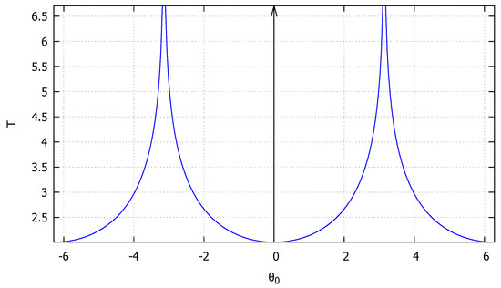
Figure 5.
Period of the nonlinear pendulum as a function of the initial conditions.
The third initial condition studied is taken as and , corresponding to an energy level equal to the critical one and is represented by the green line in Figure 2. The system is then never capable of fully absorbing the energy level but approaches such points to the left and to the right of the initial position, corresponding to the behavior described in the Section 2.2.9. The results obtained with the developed exact solution, the Newmark and RK4 methods are shown in Figure 6. As can be observed, the developed exact solution shows a good agreement with the numerical methods at the beginning. However, as this initial condition corresponds to a critical one, even small numerical drift errors will throw the numerical response to either case 1 or case 4 described above. These phenomena can be clearly observed in Figure 6 as the Newmark method drift the solution to case 1 (monotonic behavior), while the RK4 method drifts the solution to case 4 (periodic behavior). The developed exact solution, however, retains the asymptotic behavior of the system, highlighting once more the advantages of exact methods.
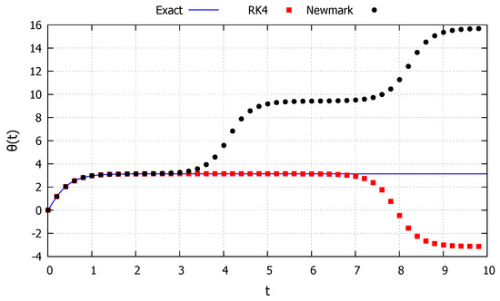
Figure 6.
Nonlinear pendulum: Case 9.
4.2. Nonlinear Pyramidal Truss
The next example studied in this section is the nonlinear pyramidal truss (Figure 7). The truss consists of n bars attached to central point, at a height H, that can only move vertically (z) and are blocked in the base, that forms a circle with radius R. The central point is subjected to the tension force of all the bars. The bars have a section with area A and are made of a material with elastic modulus E and specific mass . The natural frequency of the system in the reference configuration is then given by [17]
where .
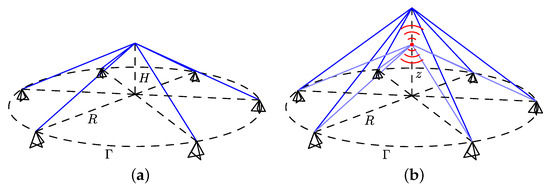
Figure 7.
Nonlinear pyramidal truss. (a) Model; (b) deformed.
Considering a logarithmic strain measure and the adimensional time and position , the equation of motion of the system can be written as follows [17]:
where and .
The force f and energy U functions of the system can then be obtained:
The internal energy function U of the nonlinear pyramidal truss is shown in Figure 8. Two initial conditions, corresponding to cases 7 and 8 from Section 2.2.7 and Section 2.2.8, respectively, are considered in order to highlight the capabilities of the developed exact solution in extreme cases. The truss has three static equilibrium points, that is, zeros of the force function f. The equilibrium points are stable, while the equilibrium point is unstable, as indicated by the curvature of this points in Figure 8. Starting from any of the stable equilibrium points () the critical velocity required to reach the unstable equilibrium point () can be obtained:
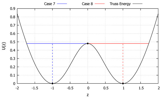
Figure 8.
Internal energy of the nonlinear pyramidal truss.
The first initial condition studied is taken as and , corresponding to an energy level equal to the critical one and is represented by the blue line in Figure 8. The system is capable of fully absorbing the energy level in a point to left of the initial condition and approaches such a point to the right of the initial condition, corresponding to the behavior described in the Section 2.2.7. The results obtained with the developed exact solution, the Newmark and RK4 methods are shown in Figure 9. As can be observed, the developed exact solution shows a good agreement with the numerical methods at the beginning. However, as this initial condition corresponds to a critical one, even small numerical drift errors will throw the numerical response to case 4, either oscillating around just one stable equilibrium point or around both of them. These phenomena can be clearly observed in Figure 9 as the Newmark method drifts the solution to case 4. For a larger time interval, the RK4 also showed such drift numerical errors. The developed exact solution, however, retains the asymptotic behavior of the system, highlighting once more the advantages of exact methods. Moreover, the dashed black line in Figure 9 represents the time s to reach the minimum value , calculated via Equation (71), showcasing its accuracy.
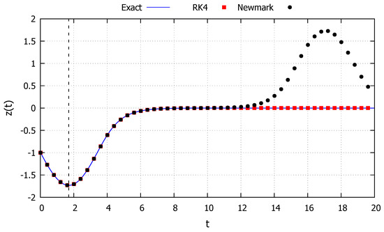
Figure 9.
Nonlinear pyramidal truss: Case 7.
The second initial condition studied is taken as and , corresponding to an energy level equal to the critical one and is represented by the red line in Figure 8. The system is capable of fully absorbing the energy level in a point to right of the initial condition and approaches such a point to the left of the initial condition, corresponding to the behavior described in Section 2.2.8. The results obtained with the developed exact solution, the Newmark and RK4 methods are shown in Figure 10. As can be observed, the developed exact solution shows a good agreement with the numerical methods at the beginning. However, as this initial condition corresponds to a critical one, even small numerical drift errors will throw the numerical response to case 4, either oscillating around just one stable equilibrium point or around both of them. These phenomena can be clearly observed in Figure 10 as the Newmark method drifts the solution to case 4. For a larger time interval, the RK4 also showed such drift numerical errors. The developed exact solution, however, retains the asymptotic behavior of the system, highlighting once more the advantages of exact methods. Moreover, the dashed black line in Figure 10 represents the time s to reach the maximum value , calculated via Equation (80), showcasing its accuracy.
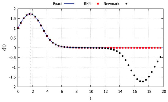
Figure 10.
Nonlinear pyramidal truss: Case 8.
4.3. Spike System
The next example of this section consists of a system where the internal energy spikes around an unstable equilibrium point. This kind of behavior is common in chemical systems or probabilistic models [25,26,27]. The equation of motion of the system can be described as follows:
The force f and energy U functions of the system can then be obtained:
The internal energy function U of the spike system is shown in Figure 11. Four initial conditions, corresponding to cases 2, 3, 5 and 6 from Section 2.2.2, Section 2.2.3, Section 2.2.5 and Section 2.2.6, respectively, are considered in order to highlight the capabilities of the developed exact solution in extreme cases. The system has one unstable equilibrium point at .
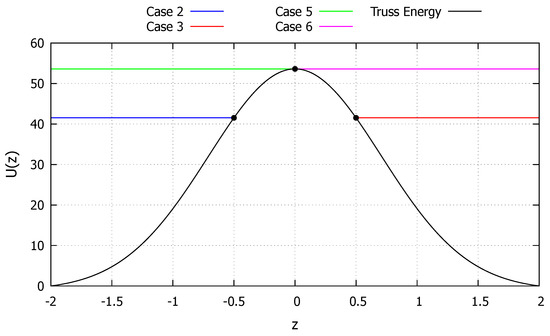
Figure 11.
Internal energy of the spike system.
The first initial condition studied is taken as and , corresponding to an energy level that makes the system reaches the maximum point and is represented by the blue line in Figure 11. The system is capable of fully absorbing the energy level only to a point to right of the initial condition, corresponding to the behavior described in the Section 2.2.2. The results obtained with the developed exact solution, the Newmark and RK4 methods are shown in Figure 12. As can be observed, the developed exact solution shows a good agreement with the numerical methods and represents well the general parabolic behavior. Moreover, the dashed black line in Figure 12 represents the time s to reach the maximum value, calculated via Equation (35), showcasing its accuracy.
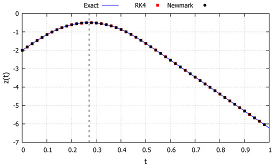
Figure 12.
Spike system: Case 2.
The second initial condition studied is taken as and , corresponding to an energy level that makes the system reach the minimum point and is represented by the red line in Figure 11. The system is capable of fully absorbing the energy level only to a point to left of the initial condition, corresponding to the behavior described in Section 2.2.3. The results obtained with the developed exact solution, the Newmark and RK4 methods are shown in Figure 13. As can be observed, the developed exact solution shows a good agreement with the numerical methods and represents well the general parabolic behavior. Moreover, the dashed black line in Figure 13 represents the time s to reach the maximum value, calculated via Equation (42), showcasing its accuracy.
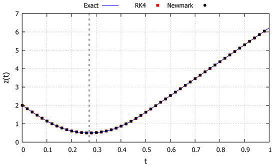
Figure 13.
Spike system: Case 3.
The third initial condition studied is taken as and , corresponding to an energy level equal to the critical one, making the system approach the critical point and is represented by the green line in Figure 11. The system is never capable of fully absorbing the energy level but approaches such a point to right of the initial condition, corresponding to the behavior described in the Section 2.2.5. The results obtained with the developed exact solution, the Newmark and RK4 methods are shown in Figure 14. As can be observed, the developed exact solution shows a good agreement with the numerical methods and represents well the general asymptotic behavior.
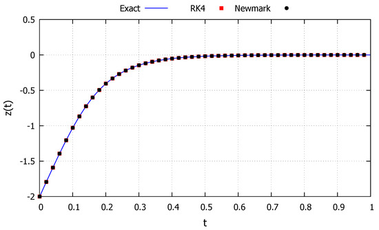
Figure 14.
Spike system: Case 5.
The fourth initial condition studied is taken as and , corresponding to an energy level equal to the critical one, making the system approach the critical point and is represented by the magenta line in Figure 11. The system is never capable of fully absorbing the energy level but approaches such a point to left of the initial condition, corresponding to the behavior described in Section 2.2.6. The results obtained with the developed exact solution, the Newmark and RK4 methods are shown in Figure 15. As can be observed, the developed exact solution shows a good agreement with the numerical methods and represents well the general asymptotic behavior.
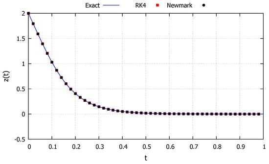
Figure 15.
Spike system: Case 6.
5. Discussion and Conclusions
In this work, exact solutions regarding second-order nonlinear autonomous undamped differential equations were developed. The behavior of the solution was linked to its energy level and nine classes of solutions were identified. The exact solutions were constructed via a suitable parametrization of the unknown function to a capable class that encapsulates its nonlinear response. The solution was shown to exist and be well-defined over all cases, for a general nonlinear form of the differential equation. Illustrative examples considering different types of nonlinearity were used to further validate the obtained exact solutions.
In future works, the exact solution could perhaps be extended to damped systems. For undamped systems, the energy level is constant and so, the topology of the solution remains the same as the system evolves. For damped systems, this is not generally the case. The solution can pass from one topological form to another as the energy level of the system changes. These considerations could be taken into account when proposing a new parametrization to the solution.
The extension of the exact solution to non-autonomous systems or systems with multiple degrees of freedom is not trivial. In these cases, the solution can be chaotic and so, identifying a general behavior to propose a parametrization seems to be a very difficult task. For the non-autonomous case, a scalable form could perhaps be used to parametrize the solution. In this case, attention should be made to the change of suitable form of the parametrization as the solution evolves.
Funding
This research received no external funding.
Institutional Review Board Statement
Not applicable.
Informed Consent Statement
Not applicable.
Data Availability Statement
No new data was created in this study.
Conflicts of Interest
The author declares no conflict of interest.
Abbreviations
The following abbreviations are used in this manuscript:
| IVP | initial value problem |
| ODE | ordinary differential equation |
References
- Lenci, S. Exact solutions for coupled Duffing oscillators. Mech. Syst. Signal Process. 2022, 165, 108299. [Google Scholar] [CrossRef]
- Nuttall, A.K.; Hartree, D.R.; Porter, A. The Response of a Non-Linear Electric Circuit to an Impulse. Math. Proc. Camb. Philos. Soc. 1936, 32, 304–320. [Google Scholar] [CrossRef]
- Goldstein, H.; Poole, C.P.; Safko, J.L. Classical Mechanics, 3rd ed.; Pearson: Upper Saddle River, NJ, USA, 2001. [Google Scholar]
- Zhang, Y.Z. Exact polynomial solutions of second order differential equations and their applications. J. Phys. A Math. Theor. 2012, 45, 065206. [Google Scholar] [CrossRef]
- Ghaemi, M.B.; Gordji, M.E.; Alizadeh, B.; Park, C. Hyers-ulam stability of exact second-order linear differential equations. Adv. Differ. Equ. 2012, 2012, 36. [Google Scholar] [CrossRef][Green Version]
- Liao, S.; Tan, Y. A General Approach to Obtain Series Solutions of Nonlinear Differential Equations. Stud. Appl. Math. 2007, 119, 297–354. [Google Scholar] [CrossRef]
- Bartha, F.A.; Krisztin, T.; Vígh, A. Stable periodic orbits for the Mackey-Glass equation. J. Differ. Equ. 2021, 296, 15–49. [Google Scholar] [CrossRef]
- Burmasheva, N.; Prosviryakov, E. Exact Solutions to Navier–Stokes Equations Describing a Gradient Nonuniform Unidirectional Vertical Vortex Fluid Flow. Dynamics 2022, 2, 175–186. [Google Scholar] [CrossRef]
- Carravetta, F. On the solution calculation of nonlinear ordinary differential equations via exact quadratization. J. Differ. Equ. 2020, 269, 11328–11365. [Google Scholar] [CrossRef]
- Liu, H.; Geng, Y. Symmetry reductions and exact solutions to the systems of carbon nanotubes conveying fluid. J. Differ. Equ. 2013, 254, 2289–2303. [Google Scholar] [CrossRef]
- Korman, P.; Li, Y. Exact multiplicity of positive solutions for concave–convex and convex–concave nonlinearities. J. Differ. Equ. 2014, 257, 3730–3737. [Google Scholar] [CrossRef]
- Cheviakov, A.F. Exact closed-form solutions of a fully nonlinear asymptotic two-fluid model. Phys. D Nonlinear Phenom. 2018, 370, 14–28. [Google Scholar] [CrossRef]
- Tur, A.; Yanovsky, V.; Kulik, K. Vortex structures with complex points singularities in two-dimensional Euler equations. New exact solutions. Phys. D Nonlinear Phenom. 2011, 240, 1069–1079. [Google Scholar] [CrossRef]
- Volpert, V.; Nec, Y.; Nepomnyashchy, A. Exact solutions in front propagation problems with superdiffusion. Phys. D Nonlinear Phenom. 2010, 239, 134–144. [Google Scholar] [CrossRef]
- MacNeil, J.M.L.; Smyth, N.F.; Assanto, G. Exact and approximate solutions for optical solitary waves in nematic liquid crystals. Phys. D Nonlinear Phenom. 2014, 284, 1–15. [Google Scholar] [CrossRef]
- Zubarev, N.; Zubareva, O. Exact solutions for the shape of a two-dimensional conducting liquid drop in a non-uniform electric field. Phys. D Nonlinear Phenom. 2012, 241, 921–928. [Google Scholar] [CrossRef]
- Santana, M.V.B.; Gonçalves, P.B.; Silveira, R.A.M. Closed-form solutions for the symmetric nonlinear free oscillations of pyramidal trusses. Phys. D Nonlinear Phenom. 2021, 417, 132814. [Google Scholar] [CrossRef]
- Newmark, N.M. A Method of Computation for Structural Dynamics. J. Eng. Mech. Div. 1959, 85, 67–94. [Google Scholar] [CrossRef]
- Runge, C. Ueber die numerische Auflösung von Differentialgleichungen. Math. Ann. 1895, 46, 167–178. [Google Scholar] [CrossRef]
- Tenenbaum, M.; Pollard, H. Ordinary Differential Equations; Dover Publications Inc.: Mineola, NY, USA, 1985. [Google Scholar]
- Beléndez, A.; Pascual, C.; Méndez, D.I.; Beléndez, T.; Neipp, C. Exact solution for the nonlinear pendulum. Rev. Bras. Ensino Física 2007, 29, 645–648. [Google Scholar] [CrossRef]
- Press, W.H.; Teukolsky, S.A.; Vetterling, W.T.; Flannery, B.P. Numerical Recipes 3rd Edition: The Art of Scientific Computing; Cambridge University Press: Cambridge, UK, 2007. [Google Scholar]
- Beléndez, A.; Hernández, A.; Márquez, A.; Beléndez, T.; Neipp, C. Analytical approximations for the period of a nonlinear pendulum. Eur. J. Phys. 2006, 27, 539–551. [Google Scholar] [CrossRef]
- Lima, F.M.S. Simple ‘log formulae’ for pendulum motion valid for any amplitude. Eur. J. Phys. 2008, 29, 1091–1098. [Google Scholar] [CrossRef]
- Grimshaw, R. Nonlinear Ordinary Differential Equations; Taylor and Francis: Boca Raton, FL, USA, 1993. [Google Scholar]
- Jordan, D.; Smith, P. Nonlinear Ordinary Differential Equations: An Introduction for Scientists and Engineers; Oxford University Press: Oxford, UK, 2007. [Google Scholar]
- Hermann, M.; Saravi, M. Nonlinear Ordinary Differential Equations: Analytical Approximation and Numerical Methods; Springer Link: Berlin/Heidelberg, Germany, 2016. [Google Scholar]
Disclaimer/Publisher’s Note: The statements, opinions and data contained in all publications are solely those of the individual author(s) and contributor(s) and not of MDPI and/or the editor(s). MDPI and/or the editor(s) disclaim responsibility for any injury to people or property resulting from any ideas, methods, instructions or products referred to in the content. |
© 2023 by the author. Licensee MDPI, Basel, Switzerland. This article is an open access article distributed under the terms and conditions of the Creative Commons Attribution (CC BY) license (https://creativecommons.org/licenses/by/4.0/).