Article

Description of a Dynamical Framework to Analyse the Helicopter Tail Rotor

by
Salvador Castillo-Rivera
* and
Maria Tomas-Rodriguez
School of Mathematics, Computer Science and Engineering, City, University of London, London EC1V 0HB, UK
*
Author to whom correspondence should be addressed.
Dynamics 2021, 1(2), 171-180; https://doi.org/10.3390/dynamics1020010
Submission received: 1 July 2021 / Revised: 31 July 2021 / Accepted: 3 September 2021 / Published: 12 October 2021

Abstract

:
In this work, a tail rotor is modelled with the aid of a multibody software to provide an alternative tool in the field of helicopter research. This advanced application captures the complex behaviour of tail rotor dynamics. The model has been built by using VehicleSim software (Version 1.0, Mechanical Simulation Corporation, Ann Arbor, MI, USA) specialized in modelling mechanical systems composed of rigid bodies. The dynamic behaviour and the control action are embedded in the code. Thereby, VehicleSim does not need an external link to another software package. The rotors are articulated, the tail rotor considers flap and feather degrees of freedom for each of the equispaced blades and their dynamic couplings. Details on the model’s implementation are derived, emphasising the modelling aspects that contribute to the coupled dynamics. The obtained results are contrasted with theoretical approaches and these have displayed to agree with the expected behaviour. This rotorcraft model helps to study the performance of a tail rotor under certain dynamic conditions.

1. Introduction

Helicopters have become an interesting area of study due to their flight capabilities as take-off, landing, flying forward and laterally. These are advantages over fixed-wing unmanned aircraft, however, they present disadvantages as the dependence on the weather [1]. Rotorcrafts are subjected to dynamical couplings between the various bodies conforming to the system and multiple nonlinear interactions that take place at various levels. Simulations represent an essential tool in aeronautical control system design: they help to the validation process without the need of expensive tests. The modelling and the simulation of the helicopters mechanisms along with the aerodynamic forces have allowed larger accuracy in the rotorcraft prediction of loading and performance [2].
In all fields of engineering, a realistic and accurate model of the system should be provided as the first step for any further studies. However, very often this is not an easy task. Four stages should be considered in the process of helicopter simulation: forces and moments modelling, trim analysis, nonlinear simulation and graphical outcomes interpretation. Different software packages have tackled helicopter modelling by taking a multibody system approach and these have become popular in engineering problems. The fields of application are broadening because the methodology considers rigid bodies’ displacements and deformations, general constraints, rigid motions, nonlinear forces, etc. For example, SIMPACK (SImulation of Multibody systems PACKage) [3], is a general-purpose multibody simulation software used for the dynamic analysis of any mechanical nonlinear systems. It was developed by DLR (German Aerospace Center). It provides an interface with Matlab, which allows for post-processing the results. It has been used in a wide range of studies such as ground resonance effect [4]. The work consisted of various steps: first, linearisation and the geometric stiffening were related, the simulation results were contrasted with analytical outcomes. Second, helicopter ground resonance was investigated. Finally, an eigenvalue study was carried out for the transformed system matrix results in the frequencies and damping of the system. To test the simulation method, SIMPACK results were compared to those obtained in the CAMRAD II model. Yavrucuk et al. [5] presented a new software tool called Helidyn+ (Version 1, Middle East Technical University, Ankara, Turkey). It is capable of modelling a rotorcraft, running a simple performance analysis and linearising, among others. Furthermore, it derives dynamic link libraries ready for integration into actual simulations and software environments. Thanapalan [6] presented a mathematical model of single main rotor helicopters (UH-60 Black Hawk helicopter). A UH-60 similar to Flightlab Generic Rotorcraft Model (GRM) was used for the simulation study. The model may be used for controller implementation to enhance flight handling quality and performance.
Another multibody code is DYMORE, used to model a Sikorsky UH-60A helicopter main rotor. An air loads model on lifting-line was linked to the structural model [7]. This code was used to predict the aeroelastic response and stability of helicopter rotors [8]. This provided a simple two-dimensional unsteady airfoil theory and a finite state dynamic inflow model to calculate the inflow velocity field over the rotor [9,10]. More recently, MBDyn (MultiBody Dynamics) has derived a framework for the simulation of multi-physics scenarios. Masarati [11] presented an algorithm for the real-time solution of inverse kinematics and inverse dynamics of redundant manipulators formulated in redundant coordinates. To show the benefits of this approach, three inverse kinematics problems were presented: three-link arm, feedforward control of a PA10-like robot and feedforward/back control of a bio-inspired robot. They allowed calculating positions, velocities and accelerations. In addition, an inverse dynamics problem that estimates feedforward generalised driving forces was taken into consideration [12]. Zupancic and Sodja [13] dealt with some experiences achieved with education and several industrial projects using the Dymola-Modelica environment. The authors concluded that the new object-oriented and multi-domain tools based on Modelica language were more suitable for industrial applications which not necessarily require deep insight into modelling methodologies. On the other hand, Bertogalli et al. [14] proposed a main rotor simulation program for an AGUSTA A109c helicopter (based on Automatic Dynamic Analysis of Mechanical Systems (ADAMS) general-purpose multibody simulation code). This approach enabled the importation of data from finite elements code to model flexible bodies and the linking of user-written subroutines to the main body of the program. In this way, the applied aerodynamic loads and nonmechanical phenomena were simulated [12].
A tail rotor often shows a far simpler design than the main rotor on a helicopter, its main function is to counteract the torque produced by the main rotor. The tail rotor rotates at a constant angular velocity and it does not contribute to the forward velocity of the rotorcraft in normal flight conditions. More accurate predictions of the tail rotor features in dynamic manoeuvres are required, as indicated by the Civil Aviation Authority [15]. Tail rotor failure in a helicopter can be hazardous and is an unstable condition. In fact, the helicopter’s fuselage along with the fully operational tail rotor often becomes unstable without suitable forward speed. Consequently, a full or even partial tail rotor failure could imply significant control problems. According to O’Rourke, [16], analysis of helicopter responses following a tail rotor failure display the potentially catastrophic nature of this type of problem. A new rotorcraft simulation model should be implemented to study helicopter response to tail rotor performance. The testing of fault-tolerant control schemes of air vehicles has been extensively studied by the safety of unmanned air vehicles especially vertically taking off and landing vehicles. The most critical failures that would be able to occur to these vehicles are motor and tail rotor failures, among others [17].
According to Guivarch et al. [18] the mechanisms responsible for interconnecting the several parts of the dynamical systems and their impact on the system, should be accurately estimated. In consequence, VehicleSim (VS) [19] has been chosen as the modelling platform. The tail rotor dynamical model is a new implementation that aims to connect the need for a robust tail rotor model and the control community. The dynamics’ coupling and the rotors’ dynamic loads are modelled in a single code. This is an advantage with respect to previous works such as Zupancic and Sodja [13] and Bertogalli et al. [14]. The provided equations allow designing and testing of robust control systems for rotorcrafts dynamics. This is a significant improvement with respect to works presented by Peters et al. [9], Peters and He [10], Zupancic and Sodja [13], Bertogalli et al. [14]. To guarantee the system’s behaviour, the helicopter model contains various Proportional–Integral–Derivative (PID) controllers. These controllers are chosen due to the low level of complexity to be modelled in VS. Their corresponding proportional, derivative and integral gains (different for each controller) are manually tuned [12].
A fundamental advantage of VS. as a modelling tool is based on the fact that nonlinear and coupled equations of motion are automatically derived. These are difficult to be solved analytically, VS. provides the nonlinear dynamic equations of motion in three dimensions. This is a novel feature to previous work presented by Chen [20], where the author performed a complete work using a Lagrangian approach to derive the coupled equations of motions in a helicopter blade. Furthermore, this software has allowed analysing the dynamic couplings existing on the blades through the nonlinear terms appearing in the in the equations of motion. These are the key to understand the energy exchange process between the flap and lag degrees of freedom [21]. According to Guivarch et al. [18] the designing new dynamic systems, as the helicopter main rotor, it can be often observed some differences between loads calculated by using simulation and loads measured through the first tests. As a consequence, new simulation models to predict the mechanical loads transiting through helicopter dynamic systems have been presented by the authors. A multibody dynamic approach was used to model rotorcraft mechanical systems, as well as the estimation of reaction loads and displacements at kinematic joints. Kada [22] has developed a helicopter nonlinear dynamics modelling for real-time motion simulation and control purposes. The model integrated the dynamics of the main components of a rotorcraft airframe with all features as dynamic couplings and nonlinearities. This was implemented to provide an alternative to software as GENHEL simulator (Version 1) designed by Aircraft Corporation (The Pennsylvania State University, University Park, PA, USA) and ARMCOP (Version 1) developed by US Army Research Institute (Draper, UT, USA) [23], Lawrence et al. [24]. An advanced multibody simulation of the tail rotor is presented to provide an alternative tool in this complex field. This model is complementary to Kada’s work [22]. The results have been exclusively reduced to the tail rotor, it is an approach that allows estimating the dynamic loads by simulation accurately, which helps to reduce the differences with the experimental measurements.
Regarding the previous considerations, the goal of the work is to provide a complete and accurate tail rotor model that takes into account the existing dynamics couplings using multibody software such as VS. The main contributions can be summarised as: (a) To put forward a simulation tail rotor model of a helicopter dynamic model. This approach is implemented at an embedded code, which simplifies the study of the helicopter dynamic behaviour. (b) To set out the vs. characteristics as a modelling tool in the rotorcraft field. (c) To validate the tail rotor model using theoretical approaches. (d) To describe and discuss the results obtained in a series of simulated conditions.
The structure of the article is as follows: Section 2 deals with the tail rotor dynamics. Section 3 puts forward a description of the modelling followed in this work. Section 4 studies the tail rotor coupling nonlinear dynamics. Finally, the main conclusions are provided in Section 5.

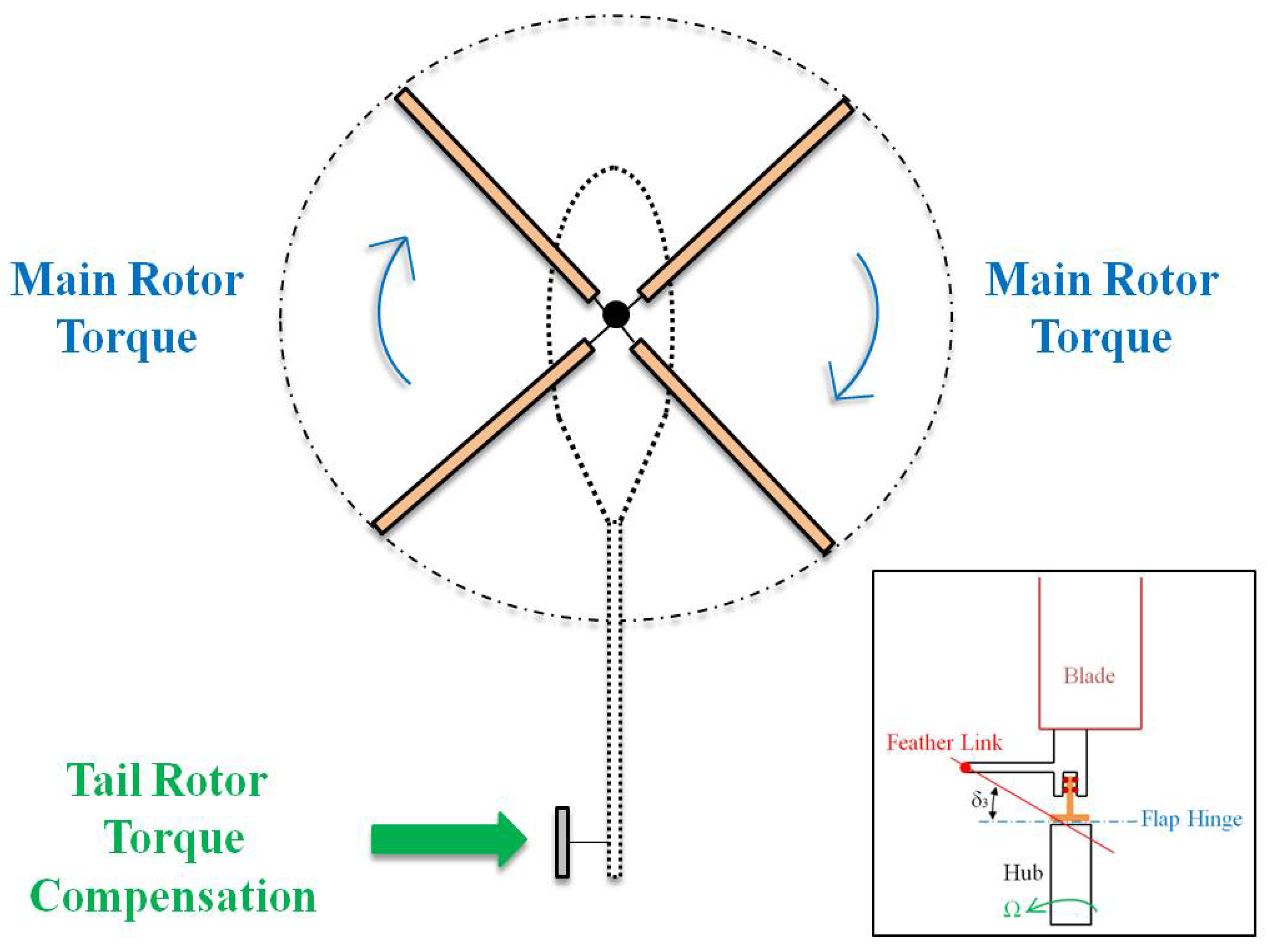
2. Tail Rotor Dynamics

In the helicopter conventional configuration, the tail rotor is mounted perpendicular to the main rotor. It counteracts the torque and the yaw motion that the main rotor disc naturally produces. Following Newton’s third law of action and reaction, the fuselage tends to rotate in the opposite direction to the main rotor’s blades as a reaction of the torque that appears. This torque must be counteracted and/or controlled before any type of flight is possible. Two anti-torque pedals allow the pilot to compensate for torque variance by providing a means of changing the pitch (angle of attack) of the tail rotor blades. This provides heading and directional control in hover and at low airspeeds. Driven by the main rotor at a constant ratio, the tail rotor produces thrust in a horizontal plane opposite to the torque reaction developed by the main rotor. Since the torque magnitude varies during the flight when power changes are made, it is necessary to accordingly modify the tail rotor’s thrust. A significant part of the engine power is needed to drive the tail rotor, especially during operations when maximum power is used. Any change in engine power output produces a change in the torque. Furthermore, power varies with the flight manoeuvre and results in a variable torque effect that must be continually corrected by the tail rotor (see Figure 1) [25,26].
The tail rotor does not need for the disc attitude to be controlled. Moreover, it does not require cyclic feathers. To obtain a lighter tail rotor design, a lag hinge is usually not included with the provision that any flap caused by disturbances is kept to an absolute minimum if not avoided. The blade flap can be triggered by the effects of forwarding flight or by aerodynamic disturbances and means of minimising this is included in a tail rotor control system, known as “delta-three” configuration. This coupling is designed to reduce transient flap angles and blade stresses [27,28]. The feather-flap coupling is kinematic feedback of the flap angular displacement to the blade feather motion that can be algebraically described as:
Δθ = −kβ
where θ is the feather angle and k is the feather-flap coupling coefficient. This acts as an aerodynamic spring for the flap mode because the lower feather means less lift. The feather-flap coupling plays an important role in flight stability and the handling qualities of the vehicle as well as the aeroelastic blade’s stability. The simplest approach is to skew the flap hinge by an angle (“delta-three”) so that it is no longer perpendicular to the blade radial axis. Then a rotation about the hinge with a flap angle β must also produce a feather change of -β tan δ3. The feedback gain for this arrangement is, therefore, k = tan δ3. Feather-flap coupling is defined in terms of the delta-three angle [25].

3. Modelling

This section describes the modelling of the tail rotor dynamics. A helicopter can be modelled following different approaches. Herein, the helicopter is considered as a rigid multibody system with different components and constraints.

3.1. General Structure of the Helicopter

Rotor modelling should include the dynamic response of the blades to a generic loading. A multibody formulation is particularly attractive; this enables to keep a representation of the blade displacement and the kinematic and the inertial properties [12]. The implemented helicopter model corresponds to a conventional model, i.e., the tail rotor is mounted perpendicular to the main rotor. It counteracts the torque and the yaw motion that the main rotor disc naturally produces [25]. This can be considered as a multibody system with several subsystems and constraints between the different degrees of freedom. vs. Lisp is the main software used in this work, and it allows the derivation of symbolic equations of motion for mechanical systems composed of multiple bodies [12]. vs. commands are used to describe the components of a multibody system in a parent/child relationship by their joints and physical constraints [19,29]. The tail rotor is set up by adding bodies according to the structure shown in Figure 2, wherein the determination of the degrees of freedom of the corresponding bodies must be taking into account concerning their parents.
The helicopter is on conventional configuration, the tail rotor’s rotation axis is transverse to the main rotor’s axis. Both subsystems are mounted on the fuselage. The rotors have equally rigid blades (four blades on the main rotor, two blades on the tail rotor) joined to a central hub on each rotor. Each rotor’s angular speed is constant, and a proportional ratio exists between them. Main rotor hinges allow three degrees of freedom on each blade: flap, lag and feather motions. Tail rotor hinges allow for two degrees of freedom: flap and feather. Feather-flap dynamical coupling is modelled on the tail rotor [12]. The fuselage has six degrees of freedom. Three translations along the (X, Y, Z) axes and three rotations around the same axes. Aerodynamic forces are not included in this model, because this work is only focused on the dynamical interactions. Its methodology have been previously used to model rotorcraft dynamic models (see [12,29]). Some geometrical and physical parameters are shown in Table 1.

3.2. Features of the Modelling Tool

VS is used to implement the model of an articulated rigid-bladed rotorcraft. One of the advantages of using this approach is that compared with hand derived equations (usually prone to errors), the automated equations give an accurate representation of the complex system’s dynamics [19].
VS consists of two main parts: vs. Lisp and vs. Browser. The first one is a set of LISP macros enabling the description of mechanical multibody systems. One of the possible outputs from this program is a C language project from which a dynamic-link library can be derived. This library contains the model’s equations of motion and it is used in the second program. vs. Browser is a powerful simulation tool that can integrate the model’s equations of motion for different initial conditions and external perturbation or events. Another output form that vs. Lisp returns is a Matlab script with the state space description of the linearised model [19].
VS Browser works out the output variables at intervals of time as the simulation is being carried out. The time history of the output variables is derived by solving the dynamical equations of motion containing the state variables. There are four types of computation methods in a vs. solver program: (a) simple arithmetic statements. (b) Numerical integration of a set of ordinary differential equations. (c) Solution of a set of simultaneous linear algebraic equations. (d) Solution of a set of simultaneous nonlinear algebraic equations [19].
The rotorcraft system is divided into its constituent bodies that are arranged in a parent/child structure. Each reference frame has a rectangular three-dimensional coordinate system that associates a unique ordered trio of numbers to each point fixed in that reference frame. n is the inertial reference frame. As new bodies are added to the system, having freedoms relative to n, local origins and axes are defined. All vs. coordinate systems are right-handed Cartesian systems defined, by (i) a reference frame wherein the coordinate system is fixed, (ii) an origin point and (iii) three reciprocally orthogonal directions that determine the axes. By “right-handed”, it means that if two of the directions are x and y, then the third direction z = x x y. The body-fixed points coincide with the corresponding global points, fixed in n when the system is on its nominal configuration. Most points are fixed in bodies but a point may be defined as mobile with its location in a body determined from its specified coordinates. This is useful for describing time-varying points of contact between one body and another one. The code starts with an inertial reference frame n, with a fixed origin, n0 and fixed directions (nx), (ny) and (nz) already defined [30].
The first lines of the code should include the commands required to initialise the system, select the unit system and declare the gravity field (optional) and its direction. Both linear and nonlinear models can be derived using various commands. When the option *linear* is set to be true or false the linear and nonlinear parts of the code are separated and chosen accordingly to the option made by the boolean variable *linear*. The nonlinear section of the code is used to generate a C file that solves the nonlinear equations of motion. The linear section is used to obtain the symbolic representation of the linearised system matrices (state-space representation).
On the other hand, the command set-defaults is employed to assign different values to parameters and initial conditions. It is also used to specify the numerical values of universal constants associated with the units system. These parameters are provided at the beginning (or end lines) of the script and can be changed for each simulation from an external file without the need of modifying the Lisp script.
An advantage of vs. is that makes use of a reduced execution time as a result of its software engineering features. On the other hand, it is not conceived to deal with the deformation problems of the bodies. However, the elasticity can be tackled, but not straightforward.

4. Results: Helicopter Model Response

The purpose of this section is to study the dynamic interactions between the flap and feather degrees of freedom. This is carried out through several simulations that use the tail rotor model described above.

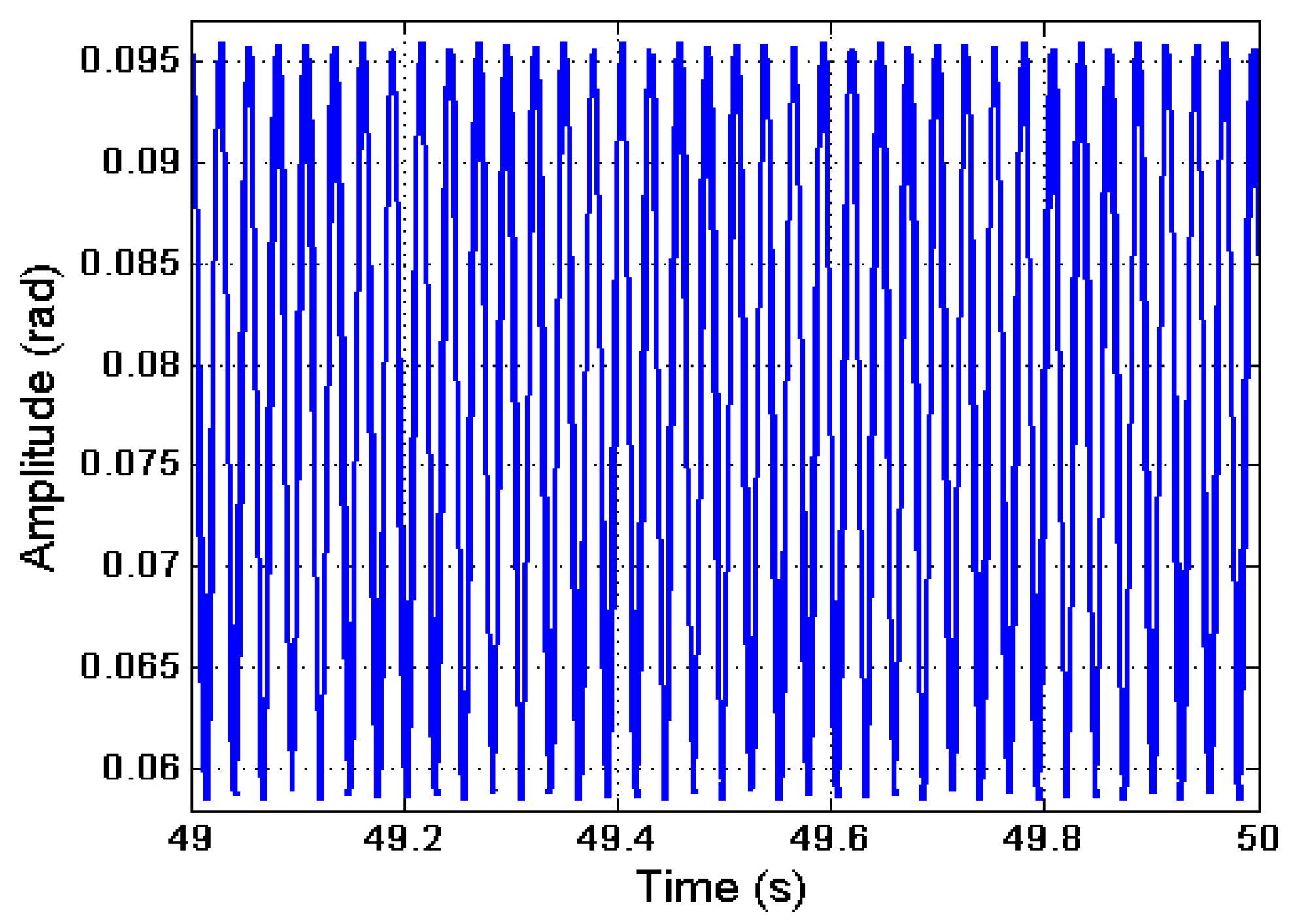
4.1. Response of the Tail Rotor Feather Angle

The rotor has no cyclic feather control, just collective to control the thrust magnitude. The rotor shaft angle is fixed by the geometry of the tail rotor installation and the helicopter yaw angle [26]. As there is no cyclic feather control, the rotor usually has flap-feather coupling via a δ3 angle set-up. The blades are assumed to be freely articulated with zero hinge offset [30]. It is known that a rotation about a hinge with flap angle β must produce a feather change of -β tan δ3. The feedback gain for this arrangement is kp = tan δ3. Positive coupling (δ3 ≥ 0) denotes negative feedback, decreasing the blade feather angle [25]. It can be found examples of the delta-three angle and the effects on the tail rotor. Fletcher et al. [31] studied the helicopter tail rotor thrust as well as the main rotor wake coupling in crosswind flight. In this work, the flap dynamics of the tail rotor blades were put down by using a delta-three angle of 45 degrees.
The following data are taken from Newman [28] to study the tail rotor dynamics. Three different cases are considered: first, a collective feather of 0.24 rad. The corresponding Fourier coefficients for the tail rotor flap motion are a1 = 0.017 rad and b1 = −0.008 rad. The coning angle is equal to 0.078 rad and the advance ratio is 0.10. Second, a collective feather is equal to 0.21 rad, a1 = 0.043 rad, b1 = −0.017 rad and coning angle is equal to 0.087 rad for an advance ratio of 0.20. Third, the collective feather is equal to 0.26 rad, a1 = 0.087 rad, b1 = −0.034 rad and the coning angle is equal to 0.122 rad for an advance ratio of 0.30. To assess the decreasing of the feather angle magnitude, a simulation is carried out for each one of the cases. The simulation time is 50 s for each of them. The corresponding feather angles and the influence of the positive coupling are shown in Table 2. As can be seen, the feather angle decreases its value for each case, as a consequence of the positive coupling. This trend follows the expected behaviour [32].

4.2. Response of the Tail Rotor Flap Motion

The blade flap motion on the tail rotor is given as Fourier series β = a 0 a 1 cos ( ω t ) b 1 sin ( ω t ) where a0, a1 and b1 are the corresponding Fourier coefficients. t is the time and ω is the blade angular speed. To examine the action of the tail rotor flap controllers, it is considered the maximum disc tilt angle βmax, according to Newman [28]:
βmax = (a12 + b12) 1/2
The values of βmax from the simulations will be compared to those of Newman [28] (see Table 3). A simulation is also carried out for each of the three cases. The flap motion of blade one is studied, the behaviour of blade two is analogous. The simulation time is 50 s in all of them.
The result of the simulation for case one is shown in Figure 3. The flap history displays that the maximum amplitude is approximately 0.095 rad. This outcome can be analysed using Equation (2). For this purpose, it is considered the coning angle as 0.078 rad and the values in Table 3. βmax can be figured out, and it is equal to 0.019 rad or (1.07 degrees). This value agrees with case 1 in Table 3. As a result, the maximum flap amplitude from the simulation should be 0.097 rad, i.e., (theoretical value). The simulated maximum flap amplitude is approximately 0.095 rad as Figure 3 shows, which is an acceptable value to be within the expected value range according to the theory within a reasonable discrepancy limit. A similar analysis can be carried out for cases two and three, respectively. The results are displayed in Table 3.

5. Conclusions

This work presents a helicopter tail rotor dynamic model, which using vs. for analysing the nonlinear dynamics inherent to these types of rotary-wing systems. The results of the simulations are compared with those available in the existing literature to validate the presented model. vs. is a program that allows building mechanical systems as a composition of several rigid bodies and ligatures by using a parent/child structure. The model under study and the relevant implementation details have been described. The main interest of this modelling approach/software is the capability of preserving and representing the existing couplings in a rotorcraft, which often, are difficult to identify/describe. The model has been derived to focus the study on the system’s dynamics only.
Dynamics coupling and rotors’ loads have been modelled in a single code. The connections between the different bodies have been established as well as their corresponding degrees of freedom. The fuselage, main and tail rotors have been implemented by using a parental structure. The tail rotor consists of several hinges linking the flap and feather degrees of freedom. The blades are attached to the hinges as rigid bodies with mass and inertial properties.
The delta-three angle and the effects on the tail rotor have also been modelled. It is worthy of note that the coupling existing between these degrees of freedom on the tail rotor has been tackled to shed light on this complex effect. This allowed the next stage in the modelling process as the feather collective control was designed and implemented according to the delta-three angle. The coupling has been validated using existing theoretical results. The feather angle diminished its value as a consequence of the positive coupling, and the maximum flap amplitude showed the expected behaviour as well. The work puts forward modelling for the cumbersome task of representing a realistic and high-fidelity rotorcraft tail rotor model considering the nonlinear dynamics. The future scope of this manuscript is to consider the influence of aerodynamic loads.

Author Contributions

Conceptualization, S.C.-R.; methodology, S.C.-R. and M.T.-R.; software, S.C.-R.; validation, S.C.-R.; formal analysis, S.C.-R.; investigation, S.C.-R.; resources, S.C.-R. and M.T.-R.; data curation, S.C.-R.; writing—original draft preparation, S.C.-R.; writing—review and editing, S.C.-R. and M.T.-R.; visualization, S.C.-R.; supervision, S.C.-R. and M.T.-R.; project administration, Not applicable.; funding acquisition, Not applicable. All authors have read and agreed to the published version of the manuscript.

Funding

This research received no external funding.

Institutional Review Board Statement

Not applicable.

Informed Consent Statement

Not applicable.

Data Availability Statement

Not applicable.

Conflicts of Interest

The authors declare no conflict of interest.

References

  1. Zaw, M.T.; Tun, H.M.; Naing, Z.M. Development of mathematical model and stability analysis for UAH. Int. J. Sci. Res. Publ. 2014, 4, 686–695. [Google Scholar]
  2. Beaulieu, M.N.; Botez, R.M. Simulation and prediction of main rotor, tail rotor, and engine parameters from flight tests. Proc. IMechE Part G J. Aerosp. Eng. 2008, 222, 817–834. [Google Scholar] [CrossRef]
  3. Available online: https://www.3ds.com/products-services/simulia/products/simpack/ (accessed on 30 June 2021).
  4. Rezaeian, A. Helicopter ground resonance analysis using multibody dynamics. In Proceedings of the ERF 2010-36th European Rotorcraft Forum, Paris, France, 7–9 September 2010. [Google Scholar]
  5. Yavrucuk, I.; Tarimci, O.; Katircioglu, M.; Kubali, E.; Yilmaz, D.C. A new helicopter simulation and analysis tool: Helidyn+. In Proceedings of the Thirty-Sixth European Rotorcraft Forum, Paris, France, 7–9 September 2010. [Google Scholar]
  6. Thanapalan, K.K.T. Modelling of a helicopter system. In Proceedings of the 1st Virtual Control Conference, Aalborg University, Aalborg, Denmark, 1 September 2010. [Google Scholar]
  7. Chierichetti, M.; McColl, C.; Ruzzene, M. Prediction of UH-60A blade loads: Insight on load confluence algorithm. AIAA J. 2014, 52, 2007–2018. [Google Scholar] [CrossRef]
  8. Bauchau, O.A.; Bottasso, C.L.; Nikishkov, Y.G. Modeling rotorcraft dynamics with finite element multibody procedures. Math. Comput. Model. 2001, 33, 1113–1137. [Google Scholar] [CrossRef]
  9. Peters, D.A.; Karunamoorthy, S.; Cao, W.M. Finite state induced flow models. Part I: Two-dimensional thin airfoil. J. Aircr. 1995, 32, 313–322. [Google Scholar] [CrossRef]
  10. Peters, D.A.; He, C.J. Finite state induced flow models. Part II: Three-dimensional rotor dis. J. Aircr. 1995, 32, 323–333. [Google Scholar] [CrossRef]
  11. Masarati, P. Computed torque control of redundant manipulators using general-purpose software in real-time. Multibody Syst. Dyn. 2014, 32, 403–428. [Google Scholar] [CrossRef]
  12. Castillo-Rivera, S.; Tomas-Rodriguez, M. Helicopter nonlinear aerodynamics modelling using vehiclesim. Adv. Eng. Softw. 2016, 100, 252–265. [Google Scholar] [CrossRef]
  13. Zupancic, B.; Sodja, A. Advanced multi-domain modelling: Advantages and dangers. In Proceedings of the UKSim 13th International Conference on Modelling and Simulation, Cambridge, UK, 30 March–1 April 2011; Available online: https://ieeexplore.ieee.org/document/5754245 (accessed on 13 September 2021).
  14. Bertogalli, V.; Bittanti, S.; Lovera, M. Simulation and identification of helicopter rotor dynamics using a general-purpose multibody code. J. Frankl. Inst. 1999, 336, 783–797. [Google Scholar] [CrossRef]
  15. Stanislawski, J. Simulation investigation of tail rotor behavior in directional maneuver of helicopter. Trans. Inst. Aviat. 2008, 193, 32–80. [Google Scholar]
  16. O’Rourke, M.J. Simulation model for tail rotor failure. J. Aircr. 1994, 31, 197–205. [Google Scholar] [CrossRef]
  17. Rajendran, S.; Gu, D. Fault tolerant control of a small helicopter with tail rotor failures in forward flight. In Proceedings of the 19th World Congress of the International Federation of Automatic Control, Cape Town, South Africa, 24–29 August 2014. [Google Scholar]
  18. Guivarch, D.; Mermoz, E.; Marino, Y.; Sartor, M. A new modeling framework to predict helicopter dynamic systems loads. In Proceedings of the 74th Annual Vertical Flight Society Forum and Technology Display 2018 (FORUM 74), Phoenix, AZ, USA, 14–17 May 2018; ISBN 978-1-5108-6329-3. [Google Scholar]
  19. Available online: https://www.carsim.com/ (accessed on 30 June 2021).
  20. Chen, R.T.N. Flap-Lag Equations of Motion of Rigid, Articulated Rotor Blades with Three Hinge Sequences. NASA Technical Memorandum 100023, 1987. Available online: https://catalogue.nla.gov.au/Record/4019811 (accessed on 13 September 2021).
  21. Castillo-Rivera, S.; Tomas-Rodriguez, M. Helicopter flap/lag energy exchange study. Nonlinear Dyn. 2017, 88, 2933–2946. [Google Scholar] [CrossRef] [Green Version]
  22. Kada, B. Helicopter nonlinear dynamics modeling for motion simulation and real-time control. In Proceedings of the 10th International Conference on Advances in Engineering and Technology (AET-18), Kuala Lumpur, Malaysia, 8–9 January 2018. [Google Scholar]
  23. Aviation School Online. The Power of the Power Curve. Available online: https://www.aviationschoolsonline.com/ (accessed on 30 June 2021).
  24. Lawrence, B.; Berger, T.; Tischler, M.B. Integrating flight dynamics & control analysis and simulation in rotorcraft conceptual design. In Proceedings of the American Helicopter Society 72nd Annual Forum, West Palm Beach, FL, USA, 17–19 May 2016. [Google Scholar]
  25. Johnson, W. Helicopter Theory; Princeton University Press: Princeton, NJ, USA, 1980. [Google Scholar]
  26. Watkinson, J. The Art of the Helicopter; Elsevier Butterworth-Heinemann: Oxford, UK, 2004. [Google Scholar]
  27. Padfield, G.D. Helicopter Flight Dynamics: The Theory and Application of Flying Qualities and Simulation Modelling; Blackwell Publishing: Hoboken, NJ, USA, 2007. [Google Scholar]
  28. Newman, S. The Foundations of Helicopter Flight; Edward Arnold: London, UK, 1994. [Google Scholar]
  29. Castillo-Rivera, S.; Tomas-Rodriguez, M. Rotorcraft fuselage/main rotor coupling dynamics modelling and analysis. Int. J. Nonlinear Sci. Numer. Simul. 2021, 22, 317–340. [Google Scholar] [CrossRef]
  30. Tomas-Rodriguez, M.; Sharp, R. Automated modelling of rotorcraft dynamics with special reference to autosim. In Proceedings of the 3rd Annual IEEE Conference on Automation Science and Engineering, Scottsdale, AZ, USA, 22–25 September 2007. [Google Scholar]
  31. Fletcher, T.M.; Brown, R.E. Helicopter tail rotor thrust and main rotor wake coupling in crosswind flight. J. Aircr. 2010, 47, 2136–2148. [Google Scholar] [CrossRef] [Green Version]
  32. Castillo-Rivera, S. Advanced Modelling of Helicopter Nonlinear Dynamics and Aerodynamics. Ph.D. Thesis, City University London, London, UK, 2014. [Google Scholar]
Figure 1. Tail rotor counteracting the torque induced by the main rotor. The inset illustrates the rotor blade feather-flap coupling via delta-three angle [25].
Dynamics 01 00010 g001
Figure 2. The main structure of the tail rotor model.
Dynamics 01 00010 g002
Figure 3. The first tail rotor blade flap motion (blue line). It is worked out with a0 = 0.078 rad, a1 = 0.017 rad and b1 = −0.008 rad. The only time between 49–50 s is shown to clearly see the flap behaviour.
Dynamics 01 00010 g003
Table 1. Rotorcraft model main parameters [12,27,30].
ParametersMagnitudeUnits
Helicopter mass2200kg
Tail rotor blade mass6.21kg
Fuselage-tail rotor longitudinal distance 6.00m
Fuselage-tail rotor vertical distance 1.72m
Delta-three angle−0.785rad
Main rotor angular speed44.40rad/s
Tail rotor gearing5.25-
Table 2. Tail rotor collective feather. The first column shows the number of cases, the second shows the numerical value of the collective feather. The third column shows the feedback change for the collective feather.
CaseCollective Feather (Rad)Collective Feather Change (Rad)
10.240.18
20.210.17
30.260.23
Table 3. Disc tilt values for the three study cases with tan δ3 = 1. The first column shows the number of cases studied and the second column corresponds to Newman’s values in degrees [28].
CaseTheoretical Maximum
Disc Tilt (Degrees)
VS Maximum
Disc Tilt (Degrees)
11.001.07
23.002.64
35.005.35
Publisher’s Note: MDPI stays neutral with regard to jurisdictional claims in published maps and institutional affiliations.

