Entry

Aircraft Wings and Morphing–Evolution of the Concepts

by
Sérgio M. O. Tavares
1,
Pedro V. Gamboa
2 and
Paulo M. S. T. de Castro
3,*
1
UID Centro de Tecnologia Mecânica e Automação (TEMA), Departamento de Engenharia Mecânica, Universidade de Aveiro, 3810-193 Aveiro, Portugal
2
Centre for Mechanical and Aerospace Science and Technologies (C-MAST-UBI), Universidade da Beira Interior, 6201-001 Covilhã, Portugal
3
Faculdade de Engenharia, Universidade do Porto, 4200-465 Porto, Portugal
*
Author to whom correspondence should be addressed.
Encyclopedia 2025, 5(3), 101; https://doi.org/10.3390/encyclopedia5030101
Submission received: 12 May 2025 / Revised: 14 June 2025 / Accepted: 2 July 2025 / Published: 14 July 2025
(This article belongs to the Section Engineering)

Definition

This encyclopedia entry provides an updated appreciation of the evolution of morphing aircraft wings, organized as follows: first, lift concepts are briefly examined; second, patents related to lift enhancement are discussed, showcasing existing technology and its evolution; finally, several technologies for morphing wings and the role of UAVs as testbeds for many innovative concepts are highlighted. The background of morphing wings is presented through a recap of lift concepts and the presentation of representative patents that describe the evolution of leading-edge and trailing-edge devices, such as flaps, slats, spoilers, and control surfaces. Although these topics are not usually detailed in reviews of morphing wings, they are deemed relevant for this encyclopedia entry.

Graphical Abstract

1. Introduction

Morphing, or the ability to change shape, aims to enhance or introduce new vehicle system performance characteristics suited to varying conditions. It generally targets two objectives: maximizing efficiency at all flight stages and facilitating different missions requiring distinct aircraft [1]. Morphing is recognized as one of twenty-five new technologies and operational improvements relevant to “green aviation” [2]. Morphing aircraft can adapt to multi-objective mission profiles, allowing them to operate more efficiently; but the adoption of morphing solutions requires attention to weight and life cycle costs, further to safety.
As with many engineering disciplines, aircraft design involves compromises among various flight condition requirements. For example, Sadraey [3] lists eighteen design constraints and requirements relevant to aircraft design, including aircraft types, maneuverability, pilot control, weight, and takeoff run, each further divided into several sub-items. A design cannot be optimized for all possible flight situations.
Wing design frequently addresses different requirements, such as takeoff and cruise phases, by incorporating movable components. Traditional solutions involving mechanisms to move parts separate from the wing’s main body, such as leading-edge slats and trailing-edge flaps, have been used for a long time. These components create a variable airfoil geometry to meet different flight needs, such as achieving higher lift or lower drag [4]. Conventional hinged control surfaces and high-lift devices that entail discrete geometry changes are often not regarded as morphing. In that sense, morphing refers to structures that undergo continuous geometric changes as a whole.
Morphing involves changes to the airframe configuration aimed at enhancing vehicle performance. There are various types and intensities of morphing. After observing the wing-sweep capability in flight—such as in the Grumman F-14 and the General Dynamics F-111—Abate and Shyy note “However, nearly all aircraft exhibit more subtle forms of morphing, such as flap deployment and retractable landing gear” [5]. In these scenarios, morphing is categorized as “active” to distinguish it from “passive” morphing, which occurs when changes in vehicle configuration do not depend on the pilot or control system, as seen in wing bending during parking or flight.
Morphing focuses on geometrical changes that optimize the fulfillment of mission profiles. While there is no universally accepted definition of morphing, discussions sometimes include conventional slats and flaps—a point that remains contentious, as many researchers argue that traditional control surfaces and high-lift devices do not belong in this category; in a stricter sense, morphing encompasses actuators, mechanisms and structures, flexible skins, and control, which may not always be integrated simultaneously [6,7]. A NATO Research and Technology Organization (RTO) publication defines morphing as a “real-time adaptation to enable multi-point optimized performance,” shifting the definition from the mechanics of morphing to the enhanced capabilities offered by a morphing vehicle (McGowan et al. [8]).
Since conventional control surfaces provide essential context for the subject, this encyclopedia entry includes them as a reference, even though they are frequently omitted from morphing discussions.
The industry’s adoption of advanced morphing technologies necessitates evidence of safety levels comparable to those of conventional control surface systems, along with aerodynamic performance and enhancements in weight and installation impact [9]. Due to the smaller scale of many unmanned aerial vehicles (UAVs) and the less stringent certification and safety constraints compared to other aviation sectors, UAVs serve as ideal platforms for innovative concepts and testing new structural solutions [10].
The growing interest in morphing aircraft is driven by the variety of new materials, including composites, rubbers, shape memory alloys (SMAs) and shape memory polymers (SMPs) in addition to traditional aeronautical materials such as aluminum alloys. Many of these materials demonstrate properties that are tailored throughout their volume, as observed in functionally graded materials (FGMs).
The design of morphing wings encompasses various scientific and engineering disciplines and innovative attitudes. Morphing can involve adjustments to the airfoil cross-section and/or wing extension (span and chord) and necessitates proper kinematics, actuation, and fulfillment of power requirements. Numerous approaches exist, each varying in complexity and ambition. Morphing studies examine cross-section design—whether constant (rectangular planform) or varying from the fuselage to the wingtip- and utilize 2D or 3D modeling techniques, comparing leading-edge (LE) and/or trailing-edge (TE) morphing with changes implemented through control surfaces like slats, flaps, and Krueger flaps. Aerodynamic pressure analysis over the wing can be simulated using Computational Fluid Dynamics (CFD) software, such as XFOIL, and interactions with wing torsion and bending are modeled comprehensively to account for aerodynamic loading, skin, reinforcement structures, and mechanisms. The optimization of morphed skin geometry, including local variations in skin thickness and adjustments in local radii, involves stress analyses in complex geometries and varying skin thickness, considering the materials used, which sometimes include less common options such as shape memory alloys or auxetic materials.
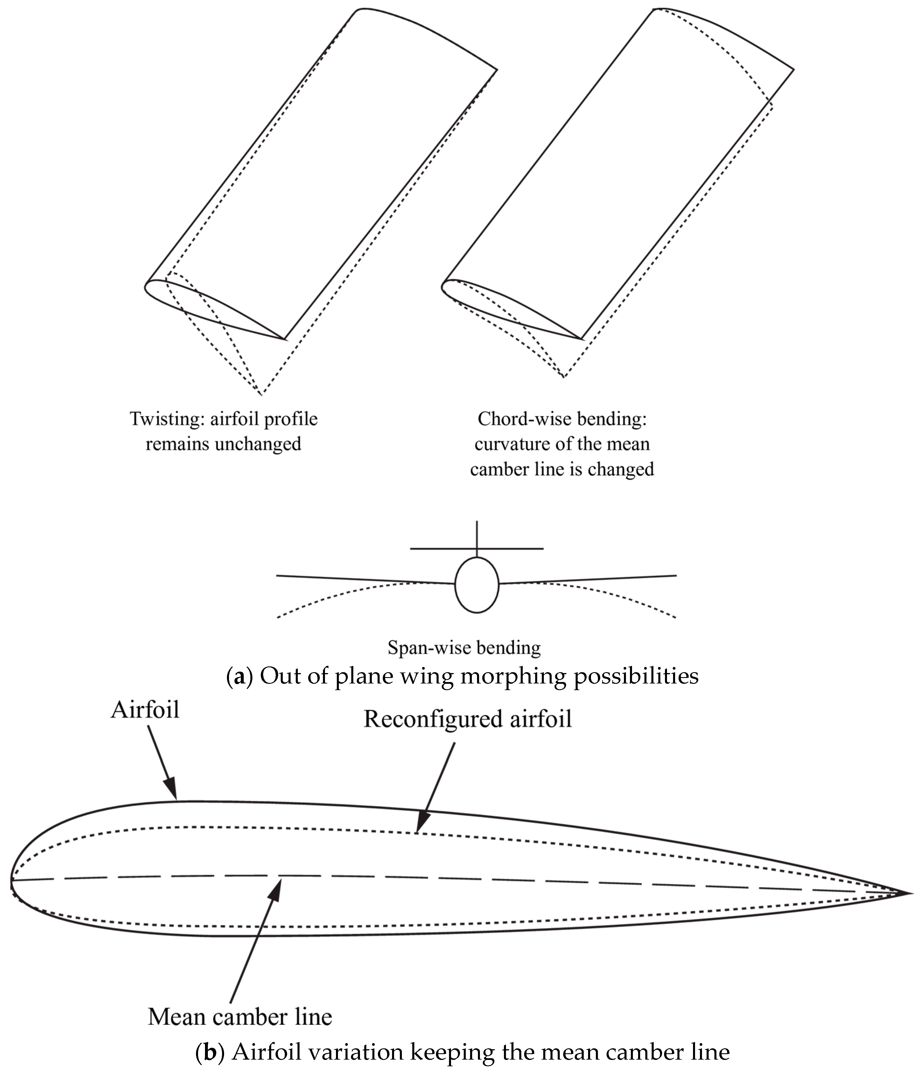
Wing morphing can be classified into three different forms of geometry alteration: (i) planform (span, chord, and sweep), (ii) out-of-plane (twist, dihedral/gull, and spanwise bending), and (iii) airfoil and profile transformations [7,11].
Vasista et al. published a critical review that compiled functional data related to various morphing-wing projects [12]. Especially noteworthy books include Smart, Intelligent Aircraft Structures (SARISTU) [13] edited by Wölcken and Papadopoulos and focused on a single EU research and development project, and Morphing Wing Technologies: Large Commercial Aircraft and Civil Helicopters [14] edited by Concilio et al., which remains one of the most thorough publications in this field. Adaptronics—Smart Structures and Materials by Sinapius [15], although not focused solely on wings, presents a comprehensive treatment of morphing.
Recent reviews of morphing wings include Li et al. [16], Ameduri and Concilio [17], Zhu et al. [18], Dong and Arief [19], and, focusing on developments in Japan, Tsushima and Tamayama [20]. These reviews are quite comprehensive; other reviews concentrate on specific aspects. For example, Mowla et al. [21] examine the use of artificial intelligence, Ahmad et al. [22] focus on polymer-based skins for morphing wing applications, and Ajaj et al. [23] investigate the aeroelasticity of morphing wings. This encyclopedia entry is not a substitute for those reviews. However, it addresses the background of the subject—the evolution of high-lift surfaces, such as flaps, slats, and Krueger flaps—which is typically not covered in the mentioned reviews but is relevant for an encyclopedia entry.
Emphasis will be placed on the morphing of wing cross-sections (airfoils). The following section outlines basic terminology and concepts related to this topic.

2. Terminology and Basic Concepts

The shape of a typical airfoil consists of several components: the LE, the TE, chord line, camber line (or mean line), and upper and lower surfaces, as illustrated in Figure 1.
Detailed background can be found in Anderson Jr.’s Introduction to Flight [25] and Fundamentals of Aerodynamics [26]. Additionally, the foundations of aerodynamic studies of airfoils are documented in Abbott and von Doenhoff’s Theory of Wing Sections: Including a Summary of Airfoil Data [27]. Basic concepts are covered in the US Naval Air Training Command’s Fundamentals of Aerodynamics [28]. Sóbester and Forrester also present current analysis tools in Aircraft Aerodynamic Design: Geometry and Optimization [29].
Figure 2 illustrates an airfoil presenting graphically the following definitions [25,30]:
  • Chord line—the straight line connecting LE and TE of an airfoil,
  • Mean camber line—the locus of points that are halfway between the upper and lower surfaces of the airfoil, and
  • Camber refers to the maximum distance between the mean camber line and the chord line, measured perpendicular to the last one.
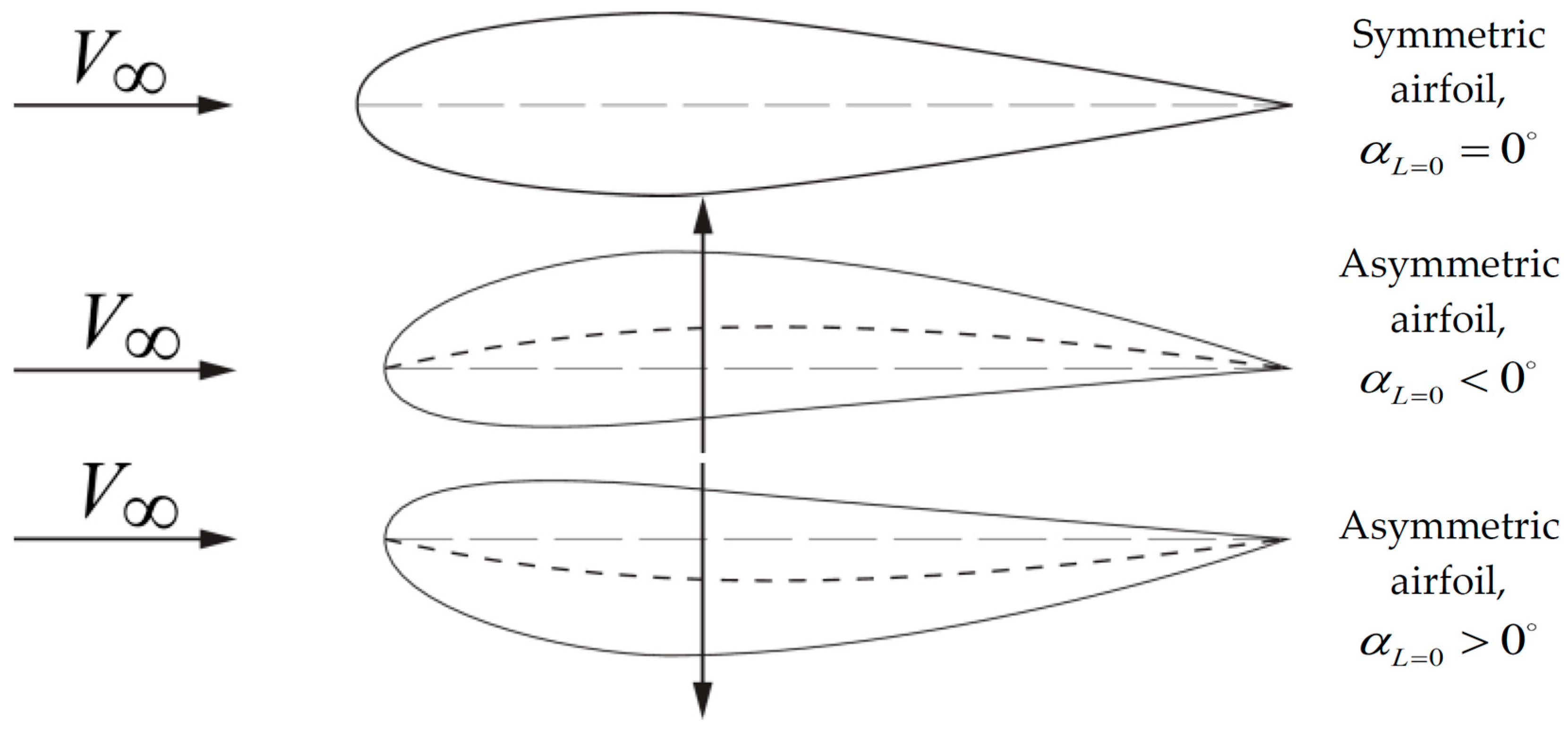
Camber variation implies changes in aerodynamic forces, as illustrated in Figure 3. Symmetric airfoils produce no lift at a zero angle of attack, while cambered airfoils generate lift by altering their zero-lift angle of attack α L = 0 .
Szodruch [31] and Szodruch and Hilbig [32] examine the concept of wing camber to attain higher performance and enhanced operational flexibility under various conditions.
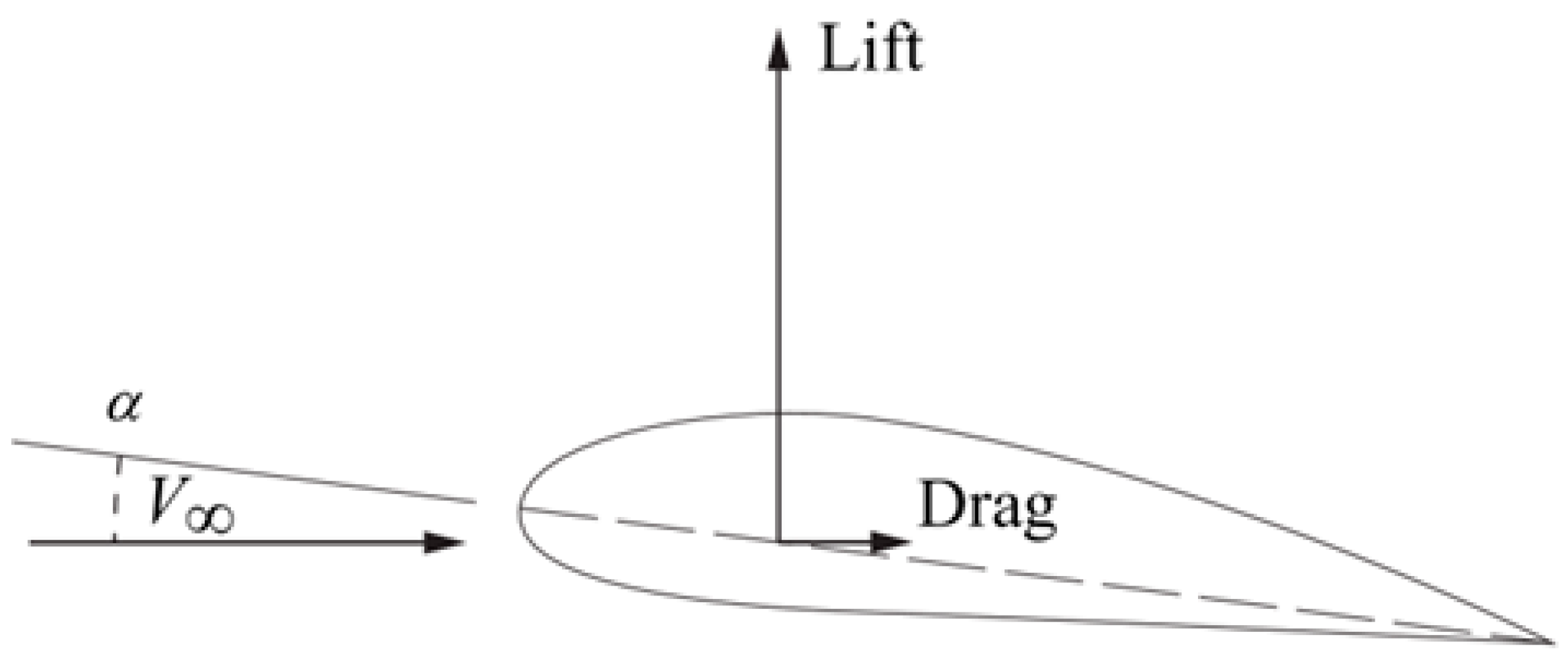
Two-dimensional (2D) coefficients are commonly used to characterize aerodynamic loading. Figure 4 illustrates the resultant aerodynamic force acting on an airfoil. The line of action of this aerodynamic force intersects the chord line at the center of pressure. The aerodynamic force consists of two components: lift and drag. Additionally, a moment is generated by this aerodynamic force: the pitching moment. Lift acts perpendicular to the relative wind while drag acts parallel to it. The center of pressure and the aerodynamic components depend on the angle of attack α , which is the angle between the relative wind direction and the chord line. Since the line of action of the aerodynamic force passes through the center of pressure, no moment is generated around that point.
The angle of incidence is formed by the wing chord line and the longitudinal axis of the fuselage [3]. This imaginary line extends from the nose to the tail of the aircraft. In this context, the angle of incidence serves as a design constant for each aircraft unless it is equipped with wings capable of rotating. Such wings are rare; for instance, the Vought F-8 Crusader features wings that the pilot can control to rotate around a single shaft. Sadraey [3] discusses the challenges associated with variable wing incidence, highlighting safety and operational concerns. These mechanisms are generally not deemed fully reliable for aviation because of fatigue, weight, and stress concentration issues.
The angle of attack α varies during different flight phases.
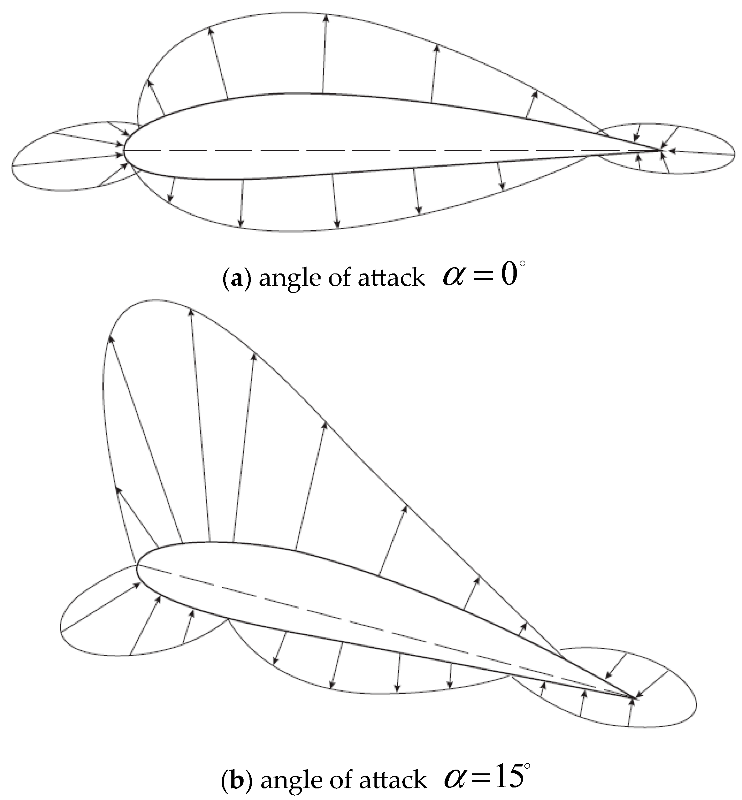
Figure 5 illustrates typical pressure distributions on an airfoil section. (In [33,34] the term “angle of incidence” is used interchangeably with “angle of attack,” which is defined as the angle between the chord line of a given airfoil section and the flight direction or the undisturbed stream).
Key 2D characteristics evaluated in wind-tunnel testing include the lift, drag, and pitching moment coefficients at the quarter-chord point and the aerodynamic center, c l , c d , and c m . These coefficients are expressed per unit length of the airfoil.
c l = l / 0.5 ρ v 2 c
c d = d / 0.5 ρ v 2 c 2
c m = m / 0.5 ρ v 2 c 2
with dynamic pressure q = 0.5 ρ v 2 , ( ρ and v are, respectively, the fluid flow density and speed) and
  • c chord length of the airfoil section
  • l lift per unit length of the airfoil
  • d drag per unit length of the airfoil
  • m pitching moment per unit length acting on the airfoil (at the aerodynamic center, quarter-chord, or another relevant point)
The wing area S is determined by multiplying the mean chord length c by the wingspan b , known as the planform area. L is the total lift on the wing, D is the total drag on the wing, and M is the total pitching moment acting on the wing. Its three-dimensional (3D) aerodynamic characteristics are:
C L = L / 0.5 ρ v 2 S
C D = D / 0.5 ρ v 2 S
C M = M / 0.5 ρ v 2 S c
Figure 6 graphically compares the variation of the lift coefficient c l with the angle of attack for both symmetric and cambered airfoils. A positively cambered airfoil generates a positive lift coefficient even at zero angles of attack, shifting the curve upward and slightly to the left, resulting in a negative zero-lift angle of attack.
Trailing-edge flaps significantly affect the lift versus angle of attack curves, commonly known as lift curves, as illustrated in Figure 7. These trailing-edge flaps alter the camber line near the trailing edge, creating an effect akin to a global increase in camber.
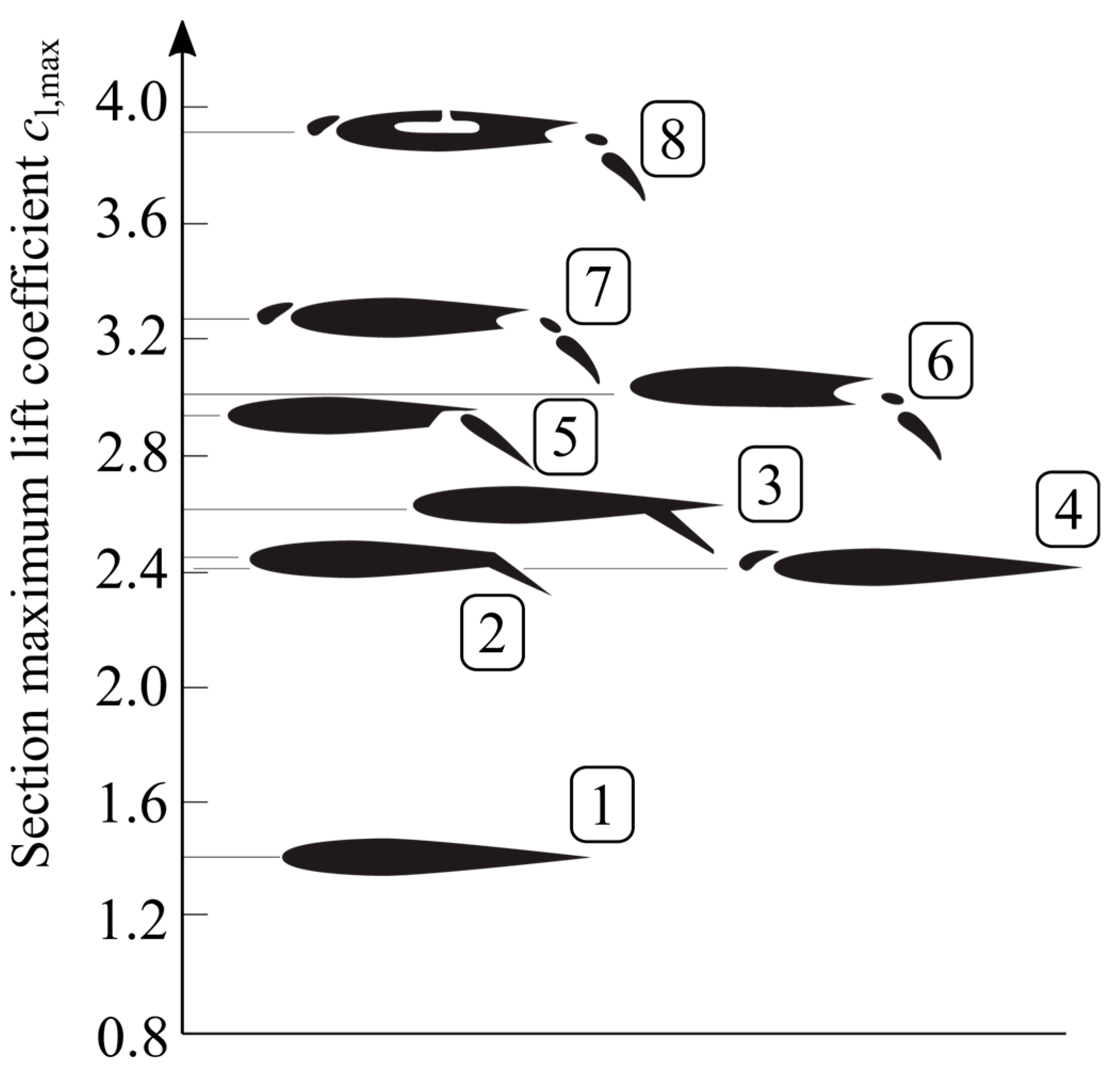
High-lift devices come in various shapes and formats. Loftin (NASA SP 468) [36] provides a summary, including Figure 8, which compares maximum lift values. Figure 9 distinguishes between leading-edge flaps and Krueger flaps.
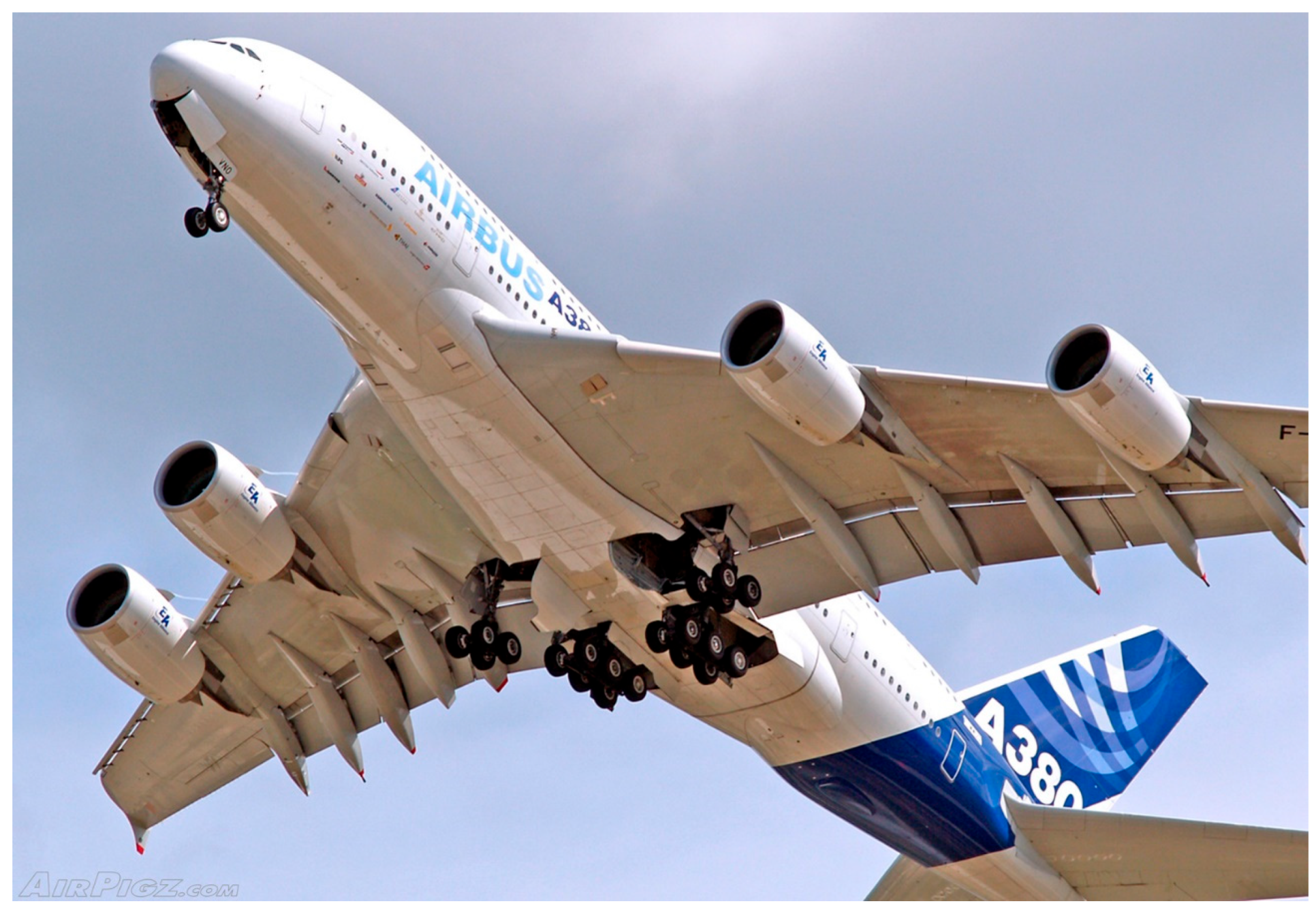
The trailing-edge flaps shown in Figure 10 illustrate deployed droops between the fuselage and the inboard engines.
Devices like leading-edge flaps, Krueger flaps, and slats reduce the pressure peak near the LE by locally adjusting the camber. Slots and slats aid in forming a new boundary layer on the main wing element, thereby alleviating the adverse effects of the initial pressure gradient. Figure 11 schematically illustrates various leading-edge devices and different types of flaps, emphasizing the wide range of solutions available for control surfaces and high-lift devices. Raymer [39] includes a comprehensive list of these devices. These conventional methods continue to evolve, as noted in the forthcoming patent survey, alongside advancements such as the VLCS (Very Long Chord Slat), studied in projects like ‘Leiser Start und Anflug’ (LEISA) [40,41,42] that aims at quieter leading-edge devices, [43].
Following this introduction, which briefly revisits lift concepts—comprehensively reviewed by van Dam [44]—the following section discusses patents related to lift enhancement as they provide relevant context for the topic at hand.

3. Patents

Innovative individuals interested in aeronautics and seeking market opportunities have generated a wealth of patents since the Wright brothers’ era. Figure 12, a facsimile of the first page of the Wright brothers’ US patent 821,393 filed in 1903, illustrates a pioneering form of morphing—the positional variation of corners a, b, c, and d of the upper ‘aeroplane’ (or points e, f, g, and h of the lower ‘aeroplane’) of the flying machine.
Engineering is not just a body of knowledge but a process; as recalled in [46], the aircraft industry originated in a bicycle shop—the Wright Cycle Exchange in Dayton, Ohio—rather than with individuals holding PhDs in physics.
Searching for patents has been made easier today through websites like Google Patents and Free Patents Online, where users can effortlessly search by topic. While flaps, slats, and other conventional control surfaces or high-lift devices are typically not regarded as morphing, they offer valuable insight into the subject’s evolution. Four topics related to aircraft wings were explored: (i) morphing and related aspects, (ii) leading-edge protection, damage, and replacement, (iii) leading-edge control surfaces (including droop-nose, slat, Krueger, etc.), and (iv) trailing-edge control surfaces.
Subsequent paragraphs showcase several important patents in chronological order, including figures taken from the patents. These figures effectively demonstrate the concepts, reinforcing the adage, “A picture is worth a thousand words.”
Rudolph’s NASA report [47] offers a comprehensive review of solutions adopted by airliners in the 1990s, highlighting many aircraft still operating today. Weisshaar provides a broad perspective, including detailed references to early patents [48].
The figures in this section are reproduced directly from patents. They typically include numbered parts, with complete definitions and details available in each patent’s text. For brevity, these lists of parts are not included here. The aim is to illustrate the ingenuity of successive patented proposals, and the selected figures are self-explanatory regarding their intended operation.

3.1. Morphing and Related Topics Subsection

Table 1 provides a chronological sample of patents related to morphing and similar subjects.
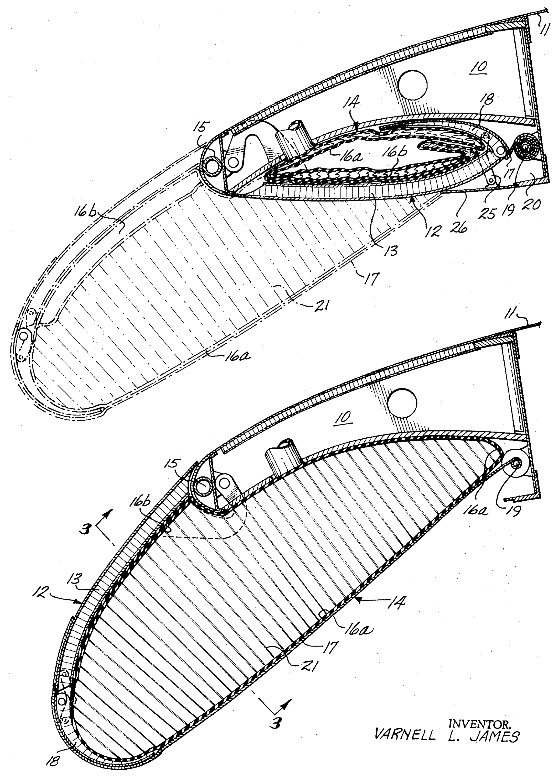
Numerous patents aim to emulate a droop-nose airfoil, highlighting the significance of morphing technology in aviation design. Notably, the Boeing patent US 3,711,039, issued in 1973, introduces an extendable inflatable nose, as illustrated in Figure 13.
In 1980, Dornier’s German patent DE 29 07 912 A1 focused on a droop-nose design (Figure 14), which is frequently referenced in DLR technical literature, particularly regarding their participation in the EU project SADE (Smart High-lift Devices for Next Generation Wings), [40,51,52,53].
Similarly, the concept is revisited in a British Aerospace patent, US 4,200,253, also from 1980, as illustrated in Figure 15.
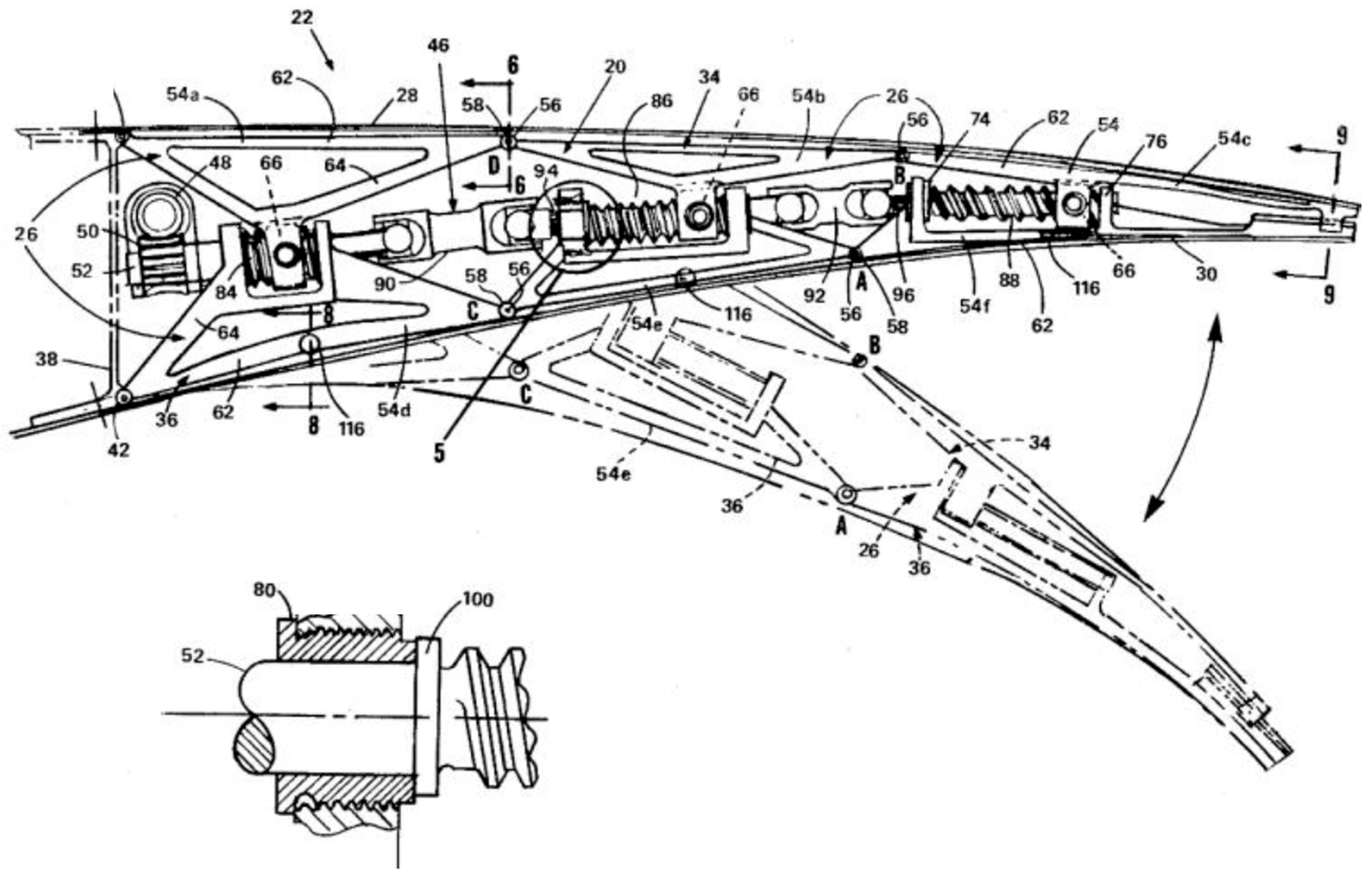
While the above patents focus on the leading edge of airfoils, various patents also address the trailing edge. For instance, Figure 16 depicts General Dynamics Corporation’s US 4,247,066 from 1981.
Another notable patent cited in DLR reports [52,57] is Boeing’s US 4,553,722, issued in 1985 and illustrated in Figure 17. This patent introduces a feature of a non-constant perimeter for the leading-edge skin while effectively eliminating undesirable effects of gaps.
According to Falcão et al. [1], morphing serves two primary functions: maximizing efficiency throughout all phases of flight and enabling a single aircraft to perform varied missions that typically require multiple specialized airplanes. A notable example of morphing, which allows for diverse missions, is US patent 4,986,493 from 1991. This patent anticipates developments in flying vehicles, such as Airbus’s single-person VTOL project Vahana [59].
The 2008 patent US 7,384,016 B2 describes an adaptive compliant wing and rotor system that NASA and the USAF developed, as detailed in Figure 18.
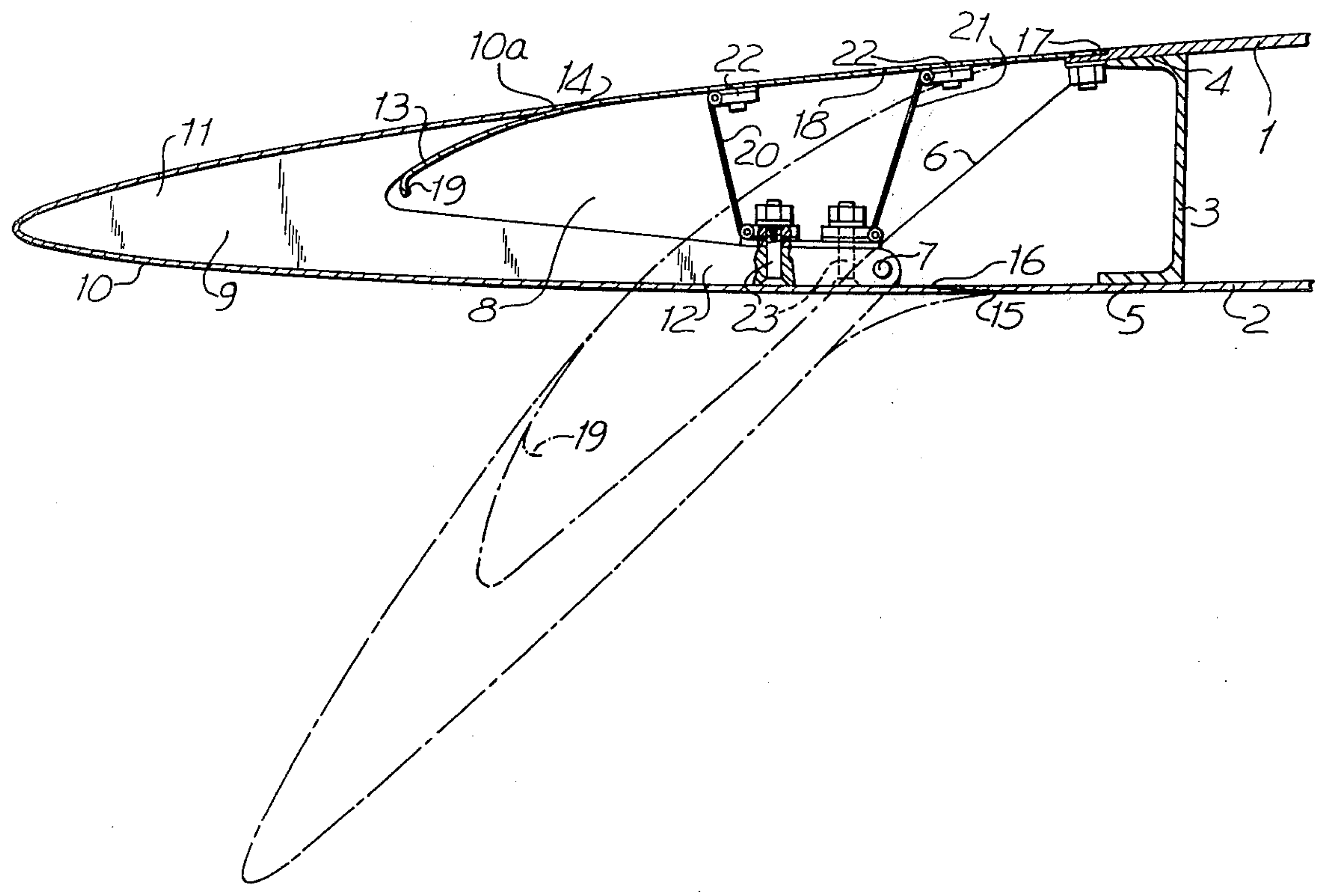
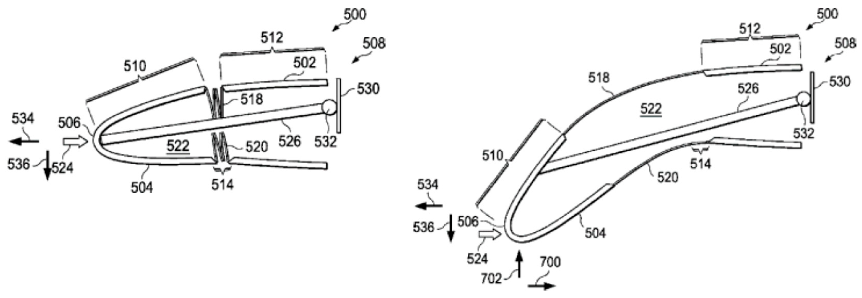
Additionally, Boeing’s patent US 8,534,611 B1 from 2013 describes a movable leading-edge device for a wing, illustrated in Figure 19. The innovation of this patent lies in the flexible connection between the LE and the rest of the airfoil. When deployed, it creates a smooth aerodynamic profile. It also showcases a non-constant perimeter for the leading edge while preventing gaps.

3.2. Leading Edge Protection, Damage, and Replacement

Table 2 lists patents related to protecting, damaging, and replacing wing leading edges chronologically.
The leading edge is particularly vulnerable to bird strikes [62,63]. A relevant example of patents dealing with this damage is WO 2014/081356 A1, issued in 2014, which outlines a method for creating a favorable sequence of structural damage while maintaining operational capability until repairs can be made.

3.3. Wing Control Surfaces

This section addresses high-lift or wing control surfaces, as illustrated in Table 3, which presents various patents in chronological order.
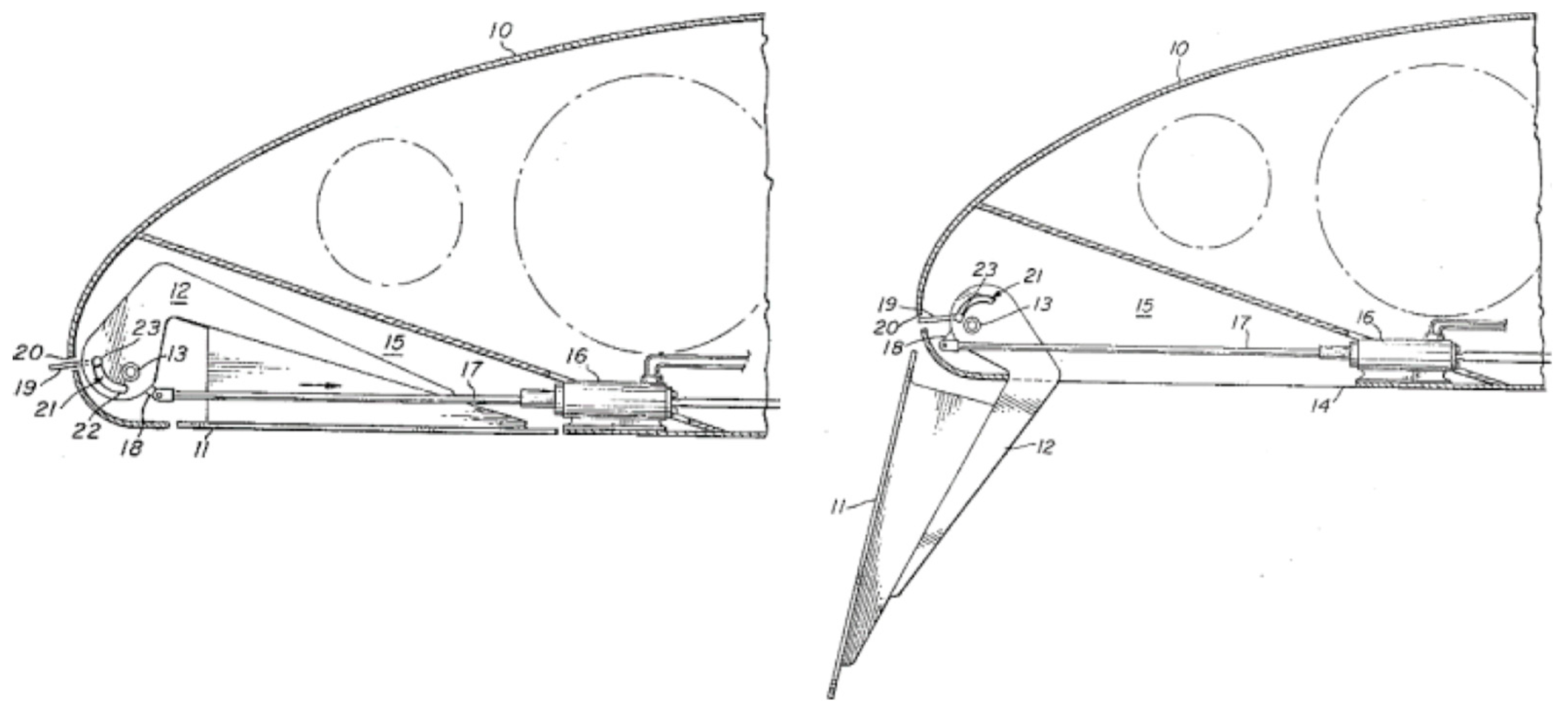
One of Boeing’s early patents, US 3,282,535 from 1966, relates to a simple flap, as shown in Figure 20. Another, Boeing’s US 3,743,219 from 1973, pertains to high-lift leading-edge devices, depicted in Figure 21.
Boeing’s patent US 4,202,519, issued in 1980, pertains to a leading-edge slat, as illustrated in Figure 22. A recent example is Boeing patent US 8,534,610 B1, which describes a slat that utilizes SMAs for optimal aerodynamic geometry, as shown in Figure 23.

3.4. Trailing Edge Innovations

Table 4 presents a selection of trailing-edge patents listed chronologically.
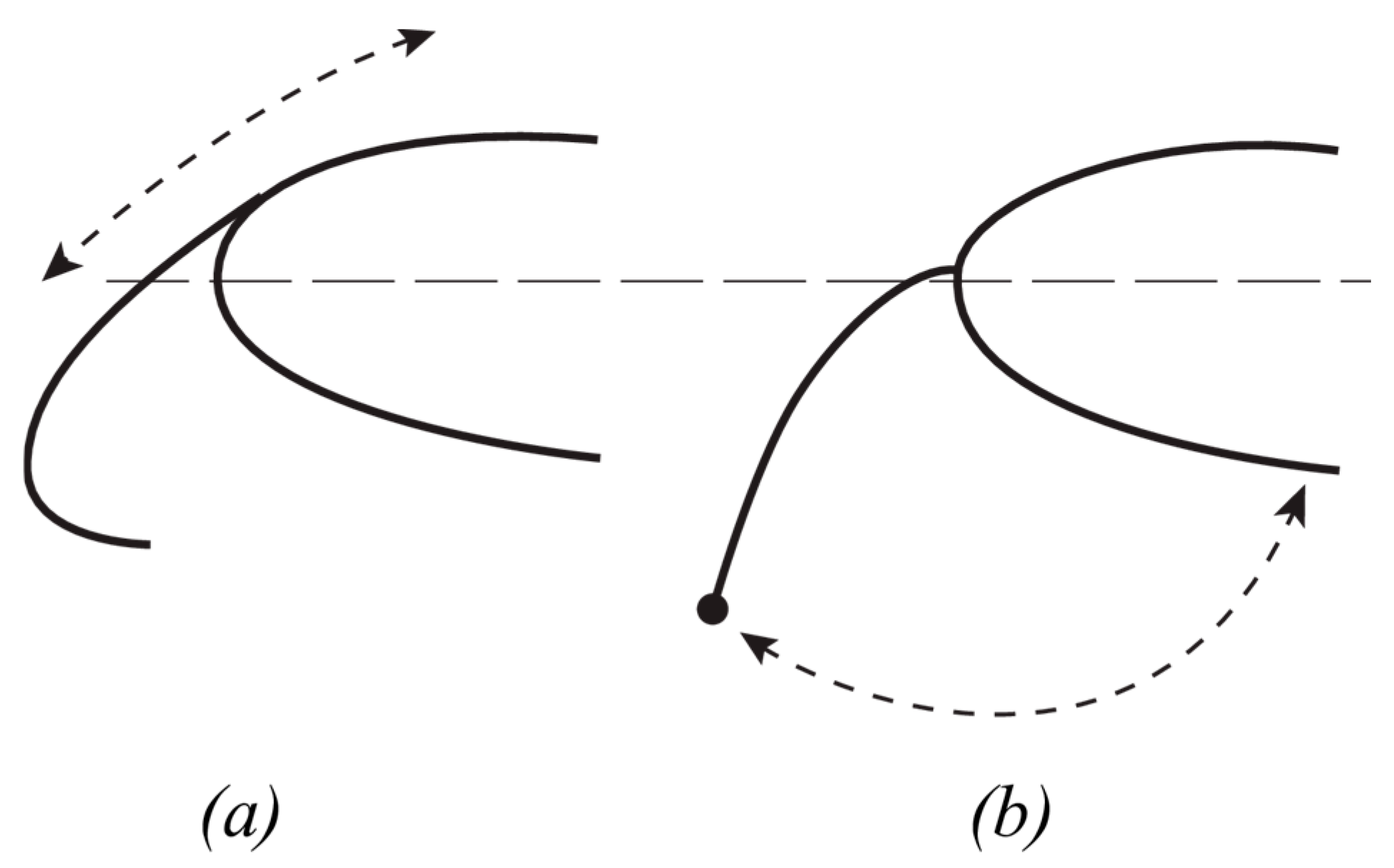
One notable patent is from Junkers, initially issued in Germany in 1939 and later issued as a US patent (2,282,516) in 1942. This patent discusses an airplane wing structure, as illustrated in Figure 24a, addressing opportunities for simplification and improvement through morphing concepts such as US patent 2,333,482, ‘Airplane Wing, Aileron, and Airplane Rudder,’ shown in Figure 24b, which is contemporary to the former.
The exploration of patents can be extensive, but the examples provided offer a substantial overview of the diverse conventional and unconventional solutions patented over time.

4. Morphing

4.1. Technologies

An aircraft design must either strike a balance among various applicable requirements or possess the ability to change shape to adapt to different services conditions. As discussed in previous sections, the traditional approach (compromising between requirements) involves using control surfaces, such as flaps and slats, which facilitate adaptability to various situations.
Morphing enhances vehicle system performance or introduces new capabilities, typically through shape changes [70]. From an innovation management perspective, morphing technology is extensively discussed by Young and Hirst [71], particularly in the chapters by Huebsch et al. [72]. Optimizing shape and morphing enhances aerodynamic efficiency, reducing fuel consumption; furthermore, morphing may enable continuous seamless solutions avoiding gaps between the wing and the control surfaces that generate airframe noise [73,74,75].
Changes in camber significantly affect lift and drag characteristics. Unlike the leading edge (LE) and trailing edge (TE), the primary load-bearing structures in the wing—the central wing box—are constrained by fuel tanks and engine mounts. Consequently, most research on wing morphing that has reached the prototype stage concentrates on the leading and trailing edges, as increasing camber typically involves deflecting the LE and TE downward. More radical multi-shape morphing could offer greater performance benefits, provided that the structural, materials, actuation, and control systems can adapt to the new challenges posed by these ambitious targets [12]. Figure 25, adapted from Sofla et al. [7], illustrates various morphing possibilities.
Gamboa et al. designed a variable span UAV wing, using a telescopic spar and rib, leading to drag reductions of up to 23% when compared to the non-morphing wing. The concept is further developed in [76], under the EU FP7 research project “Combined morphing assessment software using flight envelope data and mission based morphing prototype wing development—CHANGE” [77] into a full telescopic wing-box capable of integrating leading- and trailing-edge morphing surfaces [78,79,80] and analyzed from the viewpoint of the system mass in [81].
Comprehensive reviews on morphing in aeronautics were provided by Sofla et al. in 2010 [7] and by Barbarino et al. in 2011 [11], who categorized wing morphing concepts into planform alteration, out-of-plane transformation, and airfoil profile modification. These reviews were superseded in 2018 by the book edited by Concilio et al. [14,82], which offers a more recent and thorough examination of the subject.
Programs such as NASA’s “Aircraft Morphing” (see e.g., [83,84]) and DARPA’s “Smart Wing” alongside the “Smart Aircraft and Marine Propulsion System Demonstration—SAMPSON,” as well as “Morphing Aircraft Structures—MAS” (for details of the project, see e.g., [85,86,87], and [88] for information on DARPA), aim to develop shape-adaptive structures using active materials. In Europe, projects like DLR’s “Adaptive Flügel—ADIF” [89], along with EU initiatives such as “Smart High-lift Devices for Next Generation Wings—SADE” and “Smart Intelligent Aircraft Structures—SARISTU,” have also been highlighted. These projects are briefly described by Sinapius et al. [90] and detailed in the book edited by Wölcken and Papadopoulos [13].
Morphing aircraft that adapt to every phase of flight enhance efficiency for passengers, cargo, and military operations applications [2]. However, due to safety concerns, economic factors, and traditional conservatism, the adoption of morphing technologies in transport aircraft is progressing more slowly than in the military sector or UAVs. Gomez and Garcia highlight in their review of morphing UAVs that this area has become a hot research topic, with material advancements opening new possibilities for actuation [10]. The expanded role of UAVs, coupled with their lower regulatory and safety requirements compared to manned aircraft and the reduced costs associated with testing new solutions, has facilitated the testing of various morphing alternatives, from which leading solutions are likely to emerge.
Traditional high-lift surfaces, such as flaps and slats, influence aerodynamic lift and drag; as mentioned earlier, modifying the camber can significantly improve these effects.
In their study of a morphing leading-edge structure, Kintscher et al. [40] compare the weights of various high-lift solutions and conclude that the droop-nose design is lighter, reducing energy consumption. A droop-nose solution developed in the frame of the Clean Sky 2 program is presented by De Gaspari in [91], where one of the parameters considered is mass per unit length of the compliant structure.
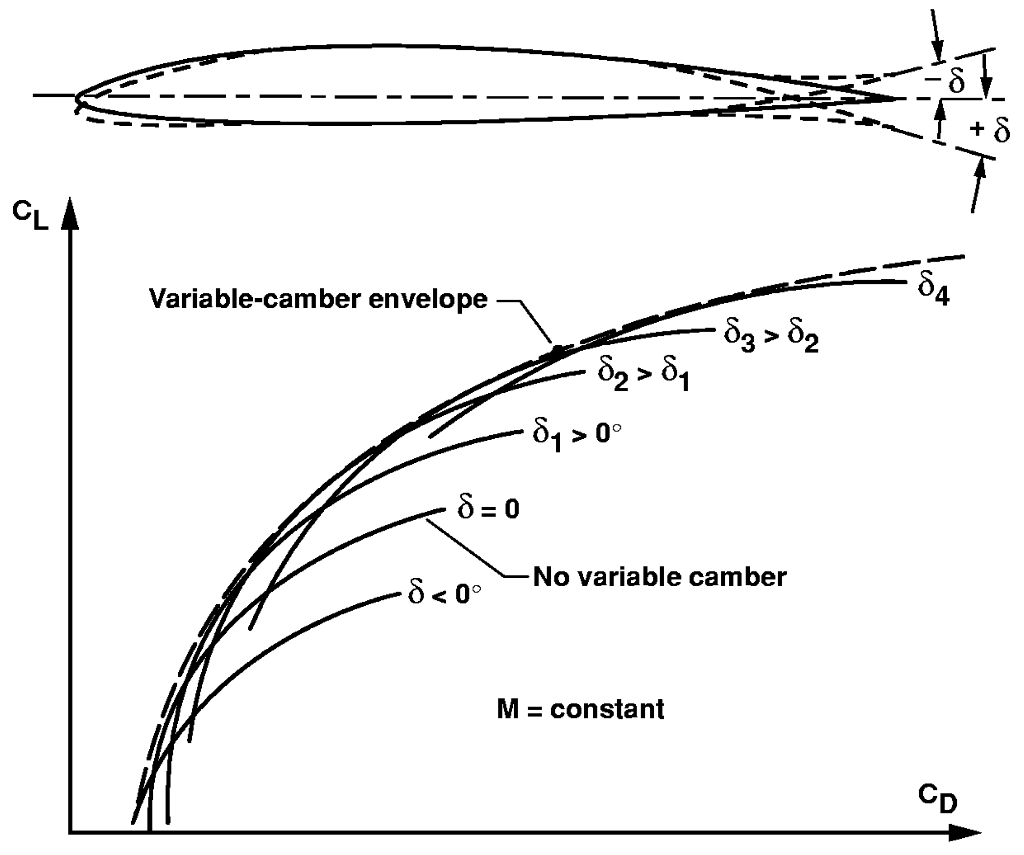
Bolonkin [92] presents a schematic representation of a drag polar diagram, Figure 26, displaying the benefits of variable-geometry wing camber for transport aircraft. Stanewsky conducted a thorough review of this topic [93].
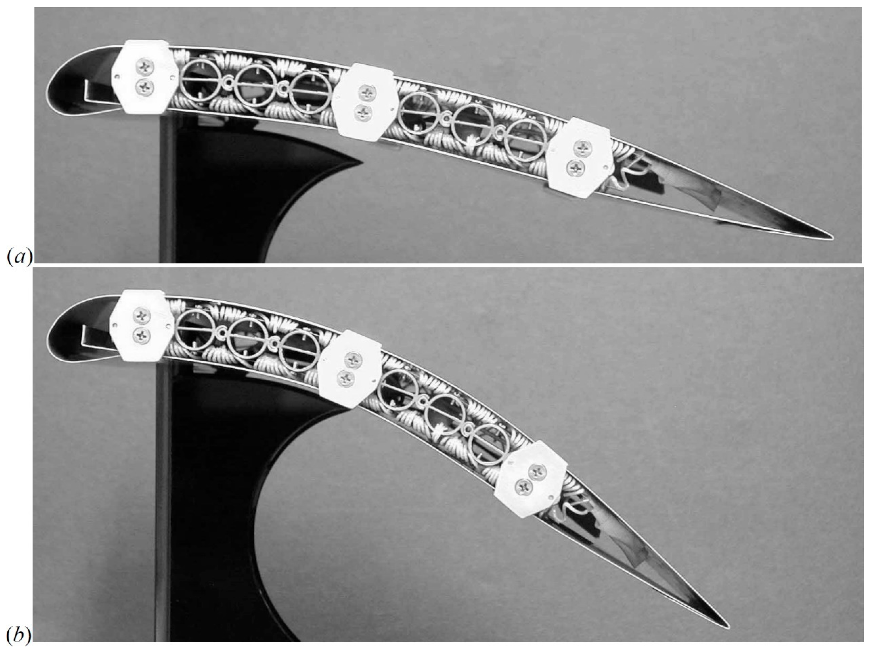
SMAs are promising materials for morphing structures. Strelec et al. [94] present an SMA airfoil, while Elzey et al. [95] focus on bio-inspired actuators for shape morphing. They emphasize that structures such as lightweight beams and panels must generate sufficiently high forces and moments to maintain a specific shape in the presence of external forces. For example, cellular metal concepts such as honeycomb, tetrahedral truss, or corrugated structures are ideal for the core components of lightweight and stiff sandwich beams and panels. Substituting conventional metallic or polymeric face sheets of cellular metal sandwich structures with smart material actuators, like SMAs, offers the potential to develop high-performance shape-morphing structures for aerospace and other demanding applications, as shown in Figure 27.
Bishay et al.’s work on applying SMAs to a lightweight camber morphing wing design relied on multidisciplinary modelling, using multiphysics software to predict aerodynamic lift and drag, and structural aspects such as stresses and displacements, [96].
The remarkable properties of matter at the nanoscale, from 1 to 100 nm, lead to the use of nanotechnologies in SMPs and shape memory polymer composites (SMPCs), with particular response to electric or thermal stimuli, which may find application in morphing wings, [22].
4D printing is a form of additive manufacturing where the material changes shape over time. Time is viewed as the fourth dimension, and this renewed interest in these solutions emphasizes the importance of understanding fatigue properties when working with morphing structures.
4D printing combines traditional 3D printing with smart materials, enabling 3D printed items to undergo time-dependent structural changes. This technology is presented by Ren et al. [97], while Chen et al. discuss solutions [98], and Guo et al. [99] focus on the 4D printing of shape memory polymer composites.
Corrugation offers a straightforward method for creating lightweight anisotropic structures that remain stable under buckling loads and exhibit energy absorption capabilities [100].
Mechanisms are also used for morphing purposes. Perera et al. [101,102] utilize an eccentric curved beam to convert actuated rotational motion into vertical displacement. The output end of this curved tube contacts the upper and lower skins of the TE, enabling it to deflect upwards or downwards based on the direction of the input rotation.
The curved tube actuator is also highlighted in the work by Bartley-Cho et al. [103], where it is applied to an uninhabited combat air vehicle (UCAV).
Vos et al. [104] introduce a structural solution featuring an open airfoil section at the tip of the trailing edge, which facilitates wing twisting through a warping displacement between the lower and upper wing skins. This system enables significant induced twisting rotation via a warping control mechanism, as depicted schematically in Figure 28, where part (c) illustrates the warping control mechanism promoting controlled relative motion between the two sides.
Not all research on morphing wings involves exotic or uncommon materials. Vocke III et al. [105] and Patnaik and Chen [106] discuss work that utilizes the standard aluminum alloy 2024. One example is the Active Adaptive Wing Camber (AAWC) concept presented by [107]. This concept is linked to the broader idea of a Mission Adaptive Wing. This wing can adjust its configuration and shape to varying flight conditions during a mission to maximize specific performance indices. The device introduced by Ricci et al. [107] builds on an original concept proposed by Hans Peter Monner from DLR.
The Clean Sky EU program utilized aluminum alloy 2024-T351 for spars and 2024-T4 for the skin during the initial Green Regional Aircraft—Integrated Technological Demonstration (GRA-ITD) phase. This research and development investigated the preliminary design and technological demonstration of a novel wing flap architecture. The feasibility of varying flap camber was assessed to evaluate the potential replacement of conventional double-slotted flaps with a single-slotted camber-morphing flap, aiming to achieve similar performance while minimizing noise and complexity [108].
Continuing with aluminum alloys, Moreira et al. examined fatigue crack propagation on the skin of a leading-edge droop nose configuration [49,109].

4.2. Aerodynamic Loads

The structural analysis of a morphing wing can consider the influence of aerodynamic forces on the state of stress. If these aerodynamic forces are low, it may be reasonable to simplify the analysis by neglecting the aero-structural coupling. However, a complex fluid-structure interaction problem must be addressed when aerodynamic forces are significant. In such cases, aerodynamic forces can alter the airfoil geometry, subsequently affecting its aerodynamic performance and necessitating an iterative solution. Several software options, such as FLUENT, are available for computational fluid dynamics (CFD). Free software developed at MIT by Mark Drela, known as XFOIL, is available for airfoil analysis [110]. Various studies report the use of XFOIL, e.g., [94,111,112,113,114,115,116,117,118].
Many authors have designed optimized morphing wing airfoil shapes without considering the underlying structural and actuation mechanisms necessary to sustain loads and perform the shape change. Secanell et al. [119] obtained optimum airfoil sections for different flight conditions of a small UAV using high fidelity aerodynamic shape optimization. The major drawback of such an approach is that the highly efficient airfoil designs are difficult to implement in practice. Gamboa et al. [120] approached the wing design optimization problem of a flexible skin around a structure made of a telescopic spar and telescopic ribs allowing changes in span chord and airfoil shape using a coupled aero-structural solver allowing for more realistic performance estimations under structural deformations due to the aerodynamic loads. Smaller improvements were obtained due to the out-of-plane displacements of the skin under aerodynamic pressure. Ukolov and Gamboa [121] proposes a wing cross-section with a trailing-edge continuous morphing solution for UAVs where a composite skin is used to provide a better stiffer airfoil aerodynamic contour. Careful aero-structural design in these compliant skins leads to better performance when compared to traditional trailing-edge surfaces.
Raither [122] investigates a variable skin stiffness concept, illustrated in Figure 29, based on adaptive stiffness elements in the skin of the airfoil and found that the aeroelastic coupling is weak since the aerodynamic loading has a negligible effect on the deformation. However, research in [107] reveals substantial differences in actuation torques when considering aerodynamic loads compared to not considering them.
Dayyani [123] presents a camber-morphing airfoil with a corrugated skin. In the context of finite element analysis (FEA), he notes that the predicted aerodynamic pressure loads will enable the estimation of out-of-plane deformations of the skin, which will be constrained to ensure that their influence on aerodynamics, especially drag, stays minimal.

4.3. Materials and Fatigue

Fatigue strength is a critical concern for aircraft, as reviewed by Tavares and de Castro [124]. Morphing involves moving parts and cyclic strains, which can lead to potential fatigue damage. A search in databases and publisher sites for “morphing and fatigue” yields relevant literature, revealing a surprisingly limited number of publications focused on the fatigue behavior of these structures despite extensive efforts dedicated to morphing concepts and technologies.
Historically, research on fatigue started with metallic structures. While morphing structures utilize various materials, metallic alloys still hold significant importance. The morphing of metallic wing structures can be divided into two main types: mechanized systems and compliant mechanisms [82]. Mechanized architectures depend on rigid subcomponents arranged in kinematic chains, while compliant mechanisms rely on the deformation of structural elements to enable morphing. As an example, fatigue crack growth (FCG) in a droop-nose morphing solution that utilizes compliant structures was modeled using the finite element method (FEM) by Moreira et al. [109].
Tavares et al. presented a concise review of fatigue related to wing morphing, emphasizing UAVs, in [125]. The existence of fatigue concerns is mentioned by Dayyani, noting that constraints based on fabrication requirements or structural integrity and fatigue are not commonly considered in morphing aircraft design [123].
In their editorial for the special issue of the “Journal of Intelligent Material Systems and Structures” dedicated to ‘Flexible Skins for Morphing Aircraft,’ Wereley and Gandhi [126] emphasized that material considerations such as toughness, erosion resistance (against sand, dust, and ice), chemical resistance, fatigue behavior, weather resistance, high strain rate capability, and the ability to recover from high strain rates must be thoroughly evaluated for practical skin applications.
It has been observed that many papers address fatigue only superficially, as noted by Barbarino [127], Mcknight [128], Bubert [129], and Vocke [130]. Other researchers as Mattioni [131] and Wildschek [132], have pointed out that composites demonstrate good fatigue performance. Barbarino et al. [127] noted that suitable experimental testing should examine the fatigue behavior of SMAs, whereas Sun [133] remarked that SMAs, SMPs, and electroactive polymers (EAPs) have poor anti-fatigue capabilities. SMAs are comprehensively reviewed by Lecce and Concilio [134], Concilio et al. [135], and Elahinia [136]. As emphasized earlier, assessing fatigue behavior is essential for evaluating the feasibility of morphing concepts, and Mahtabi et al. [137] explicitly addressed the fatigue behavior of SMAs.
Morphing structures utilize various materials, including shape-memory alloys, composites, and rubbers. Traditional aluminum alloys, such as 2024 [107], are also employed. The thickness of the selected aluminum alloy is crucial, particularly for a droop-nose morphing device, as it must require minimal power for actuation while maintaining mechanical strength and compliant geometry. Aluminum alloy sheets for aerospace applications, such as the 6xxx series, are readily available in thicknesses of 0.3 mm or greater. Thinner sheets can also be sourced in various tempers, ranging from annealed to full hard. Utilizing locally varying thicknesses could be advantageous, as this enhances local stiffness and improves compliance with desired geometric profiles. While high-speed machining is common in aeronautics, chemical milling is a viable alternative, given the generally minimal thickness of the aluminum alloy skin involved in projects.
Load spectra are essential for comprehensive fatigue analyses. Rodzewicz [138] and Rodzewicz and Glowacki [139] evaluated these load spectra in an experimental study on the airworthiness testing of a UAV structure.

4.4. Examples of Demonstrators

Civil and military aircraft have different requirements, suggesting that adopting morphing technology in civil aviation may progress more slowly because of economic factors and stringent regulatory measures [9].
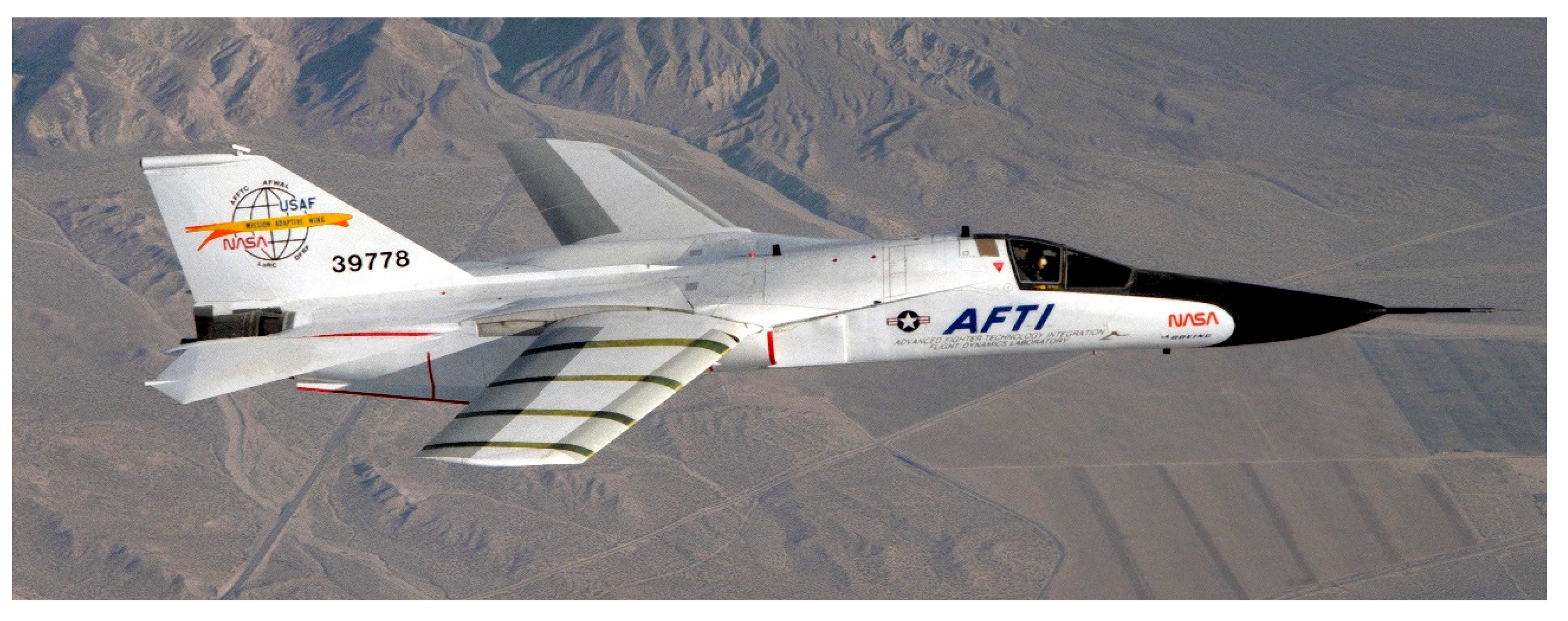
Most research on morphing wings focuses on UAVs, for example a span morphing wing by Santos et al. [140] and a bat wing with span, chord and sweep morphing by Flanagan et al. [141] yet a notable example of a manned aircraft with adaptive wings is the AFTI F-111. In the early 1980s, the wings of the F-111A were replaced with ‘mission adaptive wings’ (MAW), developed by Boeing as part of a joint NASA and US Air Force project Advanced Fighter Technology Integration (AFTI). Figure 30 depicts the modified General Dynamics AFTI/F-111A Aardvark equipped with MAWs, flying over the El Paso Mountains. On the right wing, four dark bands are noticed—they mark the locations of pressure orifices used to measure surface pressures and shock locations on the MAW.
Numerous publications describe the project. Figure 31 illustrates the variable camber concept, showing flap travel for the leading edge ranging from 2° to 21° downward and for the trailing edge from 4° to 22° downward, [143,144].
Cesnik et al. [70] discuss a framework and process for evaluating vehicle morphing capability concerning objective missions, performance needs, and the technological advancements required to achieve that performance. Bonnema [144] presents the resulting schematic drag polar curves and the minimum drag envelope, as schematically shown in Figure 26 above.
Gilbert [145] outlines the morphing mechanisms involved. The chosen solution is purely mechanical (comprising mechanisms and machine elements), distinguishing it from the more innovative applications of SMAs and other modern materials. Importantly, this concept has been successfully implemented in flights with passengers onboard.
The Adaptive Compliant Trailing Edge (ACTE) project demonstrates morphing technology, a collaboration between NASA and the US Air Force Research Laboratory (AFRL). Traditional flaps, when lowered, create gaps that generate noise. NASA’s ACTE aims for a 30 percent reduction in takeoff and landing noise and improved fuel efficiency. The conventional 19-foot aluminum flaps of a NASA Gulfstream-III were replaced with ACTE wings, which feature flexible flaps that change shape and bend, constructed from composite materials. Figure 32 illustrates the aircraft in flight with its flexible flaps visible.
The aviation sector is under intense scrutiny due to its significant environmental impact and has attempted to respond through the ICAO 2050 target of ‘net zero’ emissions [147], a goal whose feasibility is heavily questioned by action groups like ‘Stay Grounded’ [148]. To improve this situation, practical and feasible solutions must be demonstrated in full-scale passenger aircraft, which are the main contributors to the problem. Nevertheless, much of the R&D dedicated to morphing wings focuses on small demonstrators, far from the necessary size. In this context, the European Union’s Clean Sky joint undertaking should be noted, particularly the TRL achieved [149]. Clean Aviation joint undertaking builds upon Clean Sky, also combining public (EU) funding with private funding from companies. It includes a large-scale project where high TRL morphing wing solutions for passenger aircraft will be developed. The EU Hybrid Electric Regional Wing Integration Novel Green Technologies—HERWINGT project, briefly mentioned in the following paragraphs, is a project within Clean Aviation aiming to design novel wing configurations that reduce fuel consumption by 15% compared to a 2020 state-of-the-art wing.
In greater detail, the Clean Sky initiative, launched in 2008, was initially organized into six Integrated Technology Demonstrators (ITDs) [150]. The subsequent Clean Sky 2, which received partial funding under Horizon 2020, became the EU’s next framework program for aeronautical research and innovation [151,152]. Public-private partnerships continue to drive advancements in this field, now under the Clean Aviation Joint Undertaking. The program’s public-private partnership seeks to engage stakeholders across the EU while maintaining focus and coherence, thereby reducing the fragmentation in other funding instruments. Demonstrators with high TRLs are expected to validate technological concepts. The vehicle-level Integrated Advanced Demonstrator Projects (IADPs) focus on creating flying demonstrator aircraft at the large passenger, regional, and rotorcraft levels to test these new technologies. Integrated Technology Demonstrators (ITDs) combine airframe, engine, and system components to demonstrate synergistic performance and benefits.
In the context of the EU Clean Sky programme, an AIRBUS A340 with a modified experimental laminar-flow wing flew in the ‘Breakthrough Laminar Aircraft Demonstrator in Europe—BLADE’ project in anticipation of flying with morphing flaps. This was part of the Smart Fixed Wing Aircraft (SFWA) project of Clean Sky.
Innovations such as adaptive winglets, morphing trailing-edge (TE) flaps, and droop noses focus on materials, structural mechanics, actuation systems, and safety and reliability issues. The goal is to develop a flexible wing that supports natural laminar flow, integrating advanced morphing active devices like droop noses, morphing trailing edges, and winglets, especially within the Green Regional Aircraft (GRA) subprogram. Outcomes of the EU-funded Clean Sky 2 REG-IADP AG2 project are described by De Gaspari and Moens in [153] and Pecora describes in details the evolution of the morphing wing concept within Clean Sky and Clean Sky 2 in [154]. Current Clean Aviation HERWINGT project continues work on morphing wings, aiming at an innovative wing for the future hybrid electric regional aircraft, [155,156,157].
The EU project “Smart Morphing & Sensing,” funded under ‘Societal Challenges—Smart, Green and Integrated Transport,’ connects novel electroactive actuators and sensors to enhance aerodynamic efficiency while reducing noise and vibration through aerostructural morphing based on real-time information. Morphing technologies hold significant potential for improving aerodynamic efficiency and decreasing noise. While the previous example includes SMAs and other less common materials, a comprehensive development process from conceptual design to the manufacturing of a morphing LE concept was conducted within the LeaTop project of CleanSky’s GRA ITD, where the skin material was assumed to be an aluminum alloy with a modulus of elasticity (E) of 71 GPa, [158,159]. Reference to the E value invokes the relevance of this parameter in the choice of skin materials, given its impact upon the actuation forces.

4.5. Biomimetics

The philosophy of design inspired by nature is generally addressed by Matteck in his book “Design in Nature: Learning from Trees” [160], yet specifics concerning flying were dealt with as early as the nineteenth century by Lilienthal [161]. While this entry mainly focuses on camber morphing solutions, beyond this emphasis, avian-inspired morphing UAVs is a subject of growing interest though remaining at low technological readiness levels. Biomimetic concepts are discussed in the review by Harvey et al. concerning avian-inspired solutions [162]. Ozbeck et al. note that the structures used in aircraft are much simpler than the wings of birds [163], which pose specific challenges associated with the interaction effects between control surfaces and degrees of freedom, as examined by Jeger [164]. A markedly different case of bio-inspired morphing, presented by Zhao et al. [165], pertains to the cone of an aerospace vehicle. An additional bioinspired approach with potential for future aircraft and unmanned aerial vehicles designs is the avian perching maneuvers providing an enhanced agility, energy efficiency, and precision of landing strategies, particularly in constrained or dynamically changing environments, [166]. These avian perching maneuvers are currently being extensively explored for morphing-wing drones, as it enables rapid reductions in kinetic energy in diverse scenarios [167].
Bird flight has inspired aeronautical engineers since the late nineteenth century, beginning with Lilienthal. Current research on avian-inspired morphing involves UAVs. The challenges to be addressed are substantial because of the subtle control methods and significant dynamic shape changes used by birds. Nevertheless, progress is steadily being made, as evidenced by projects such as CGull and LisHawk, details of which are found in refs. [168] and [169], respectively.

4.6. Sinthetizing

Table 5 presents the evolution of wing morphing technologies, highlighting characteristic features of each period considered. Table 6 gives a chronological sequence of some projects with an impact on evolution. In both tables, there is no pretense of exhaustiveness, but the intention of providing a bird’s-eye view of important occurrences over time. Weisshaar [48] presents a detailed historical perspective. Less wide-reaching, but deeper in some topics, is the historical presentation included in Chapter 1 of Concilio et al.’s book [14]. Previtali [170] gives a comprehensive list of airplanes (either experimental or production) with variable sweep wings. References [18,22,171] are sources of information on the history of morphing, whereas future trends are identified in [21,172].

5. Concluding Remarks

The trends related to the use of morphing wings in UAVs, as well as in commercial and military aircraft, are intended to enhance performance by reducing drag, improving energy efficiency, increasing range, lowering noise, and ensuring adaptability across various flight conditions and applications, while boosting wing shape-changing capabilities. Challenges encompass safety, durability, and reliability concerns, alongside maintainability, complex manufacturing, and weight management. This requires lightweight advanced materials that possess the necessary fatigue strength and advanced processes such as additive layer manufacturing (ALM), along with improved control systems and advanced actuators that automatically adjust wing shape to optimize performance. Predictive modeling and its connection to the digital twin paradigm will be a primary focus, especially in utilizing artificial intelligence (AI) to design solutions that provide enhanced intelligence and adaptability.
This concise entry emphasizes that morphing structures remain essential in aeronautics, possessing significant potential to improve flight efficiency. Current morphing concepts aim to alter geometry continuously while avoiding substantial geometric discontinuities. Furthermore, the subsequent points are emphasized:
Emphasizing demonstrators, like those in the Clean Sky and subsequent Clean Aviation programs within the European Union, organizes scattered and fragmented research efforts.
Different methods of aircraft morphing are being investigated in various fields.
The vision for morphing aircraft can be achieved through innovative materials, nanotechnology, and advancements in microfluidic control.
A global effort involves various organizations—including academic institutions, research and development entities, small and medium-sized enterprises, and large manufacturers—focused on advancements in aircraft morphing, encompassing structural aspects, mechanisms, skins, actuation, aerodynamics, and control.
The characteristics of morphing solutions may interact, adding complexity to modeling these challenges.
Morphing is not a panacea; weighing economic factors and technical advancements is essential.
The growing interest in and use of morphing technologies in the less regulated field of UAVs may serve as a testing ground for morphing aircraft in manned flight, where military and civilian applications have varying needs and constraints.
Since morphing involves the movement of components, fatigue issues must be addressed with care, especially when using unconventional materials.
Changes in camber directly affect lift and drag characteristics. Most studies that have reached the prototype stage involve developments in the leading and trailing edges, as increasing camber is achieved through their deflection. However, more radical multi-shape morphing could deliver more significant performance benefits if the structural, materials, actuation, and control systems can effectively respond to the challenges posed by more ambitious goals.

Funding

This research received no external funding.

Institutional Review Board Statement

Not applicable.

Informed Consent Statement

Not applicable.

Data Availability Statement

No new data were created or analyzed in this study. Data sharing is not applicable to this article.

Conflicts of Interest

The authors declare no conflicts of interest.

Abbreviations

AAWCActive Adaptive Wing Camber
ACTEadaptive compliant trailing edge
ADIFAdaptiver Flügel (DLR project)
AFRLAir Force Research Laboratory (US)
AFTIadvanced fighter technology integration
AFWALAir Force Wright Aeronautical Laboratories (US)
AHSAmerican Helicopter Society (US)
AIartificial intelligence
AIAAAmerican Institute of Aeronautics and Astronautics (US)
ALMadditive layer manufacturing
ASCAmerican Society for Composites (US)
ASCEAmerican Society of Civil Engineers (US)
ASMEAmerican Society of Mechanical Engineers (US)
CFDcomputational fluid dynamics
CNATRAChief of Naval Air Training (US)
DARPADefense Advanced Research Projects Agency (US)
DLRDeutschen Zentrum für Luft- und Raumfahrt
EAPelastic-active polymer
EPEuropean patent
FCGfatigue crack growth
FEAfinite element analysis
FEMfinite element method
FEUPFaculdade de Engenharia da Universidade do Porto
FGMfunctionally graded material
GRAGreen Regional Aircraft (subprogram of Clean Sky)
H2020EU research and innovation programme 2014—2020
IADPintegrated advanced demonstrator project (Clean Sky)
ICAOInternational Civil Aviation Organization (UN)
IMechEInstitution of Mechanical Engineers (UK)
ISBNinternational standard book number
ITDintegrated technological demonstrator (Clean Sky)
KRRepublic of Korea
LEleading edge
LEISALeiser Start und Anflug (project)
MASMorphing Aircraft Structures (DARPA project)
MAWmission adaptive wing
MDAOmultidisciplinary design analysis and optimization
MITMassachusetts Institute of Technology
NACANational Advisory Committee for Aeronautics (predecessor of NASA)
NASANational Aeronautics and Space Administration (US)
OMPIOrganisation Mondiale de la Propriété Intellectuelle (WIPO)
R&Dresearch and development
SADESmart High Lift Devices for Next Generation Wings (EU project)
SARISTUSmart Intelligent Aircraft Structures (EU project)
SMAshape memory alloy
SMEsmall and medium-sized enterprise
SMPshape memory polymer
SMPCshape memory polymer composite
SPIEInternational society for optics and photonics
TEtrailing edge
TRLtechnology readiness level
UAVunmanned aerial vehicle
UBIUniversidade da Beira Interior (Portugal)
UCAVuninhabited combat air vehicle
UIDR&D unit
UNUnited Nations
USUnited States
VLCSvery long chord slat
VTOLvertical take-off and landing
WIPOWorld Intellectual Property Organization (OMPI)

References

  1. Falcão, L.; Gomes, A.A.; Suleman, A. Aero-structural design optimization of a morphing wingtip. J. Intell. Mater. Syst. Struct. 2011, 22, 1113–1124. [Google Scholar] [CrossRef]
  2. Agarwal, R.K. Review of technologies to achieve sustainable (green) aviation. In Recent Advances in Aircraft Technology; Agarwal, R.K., Ed.; InTech: London, UK, 2012; Chapter 19; pp. 424–464. [Google Scholar]
  3. Sadraey, M.H. Aircraft Design: A Systems Engineering Approach; Aerospace Series; Wiley: Chichester, West Sussex, UK, 2012. [Google Scholar]
  4. van Tooren, M.; Rao, A.G.; Obert, E.; van Buijtenen, J. Applied aerodynamics and propulsion foundations: Fixed wing vehicles. In Encyclopedia of Aerospace Engineering; Blockley, R., Shyy, W., Eds.; John Wiley & Sons: Hoboken, NJ, USA, 2010. [Google Scholar]
  5. Abate, G.; Shyy, W. Bio-inspiration of morphing for micro air vehicles. In Morphing Aerospace Vehicles and Structures; Valasek, J., Ed.; John Wiley & Sons: Chichester, West Sussex, UK, 2012; pp. 41–53. [Google Scholar]
  6. Reich, G.; Sanders, B. Introduction to morphing aircraft research. J. Aircr. 2007, 44, 1059. [Google Scholar] [CrossRef]
  7. Sofla, A.Y.N.; Meguid, S.A.; Tan, K.T.; Yeo, W.K. Shape morphing of aircraft wing: Status and challenges. Mater. Des. 2010, 31, 1284–1292. [Google Scholar] [CrossRef]
  8. McGowan, A.-M.R.; Vicroy, D.D.; Busan, R.C.; Hahn, A.S. Perspectives on highly adaptive or morphing aircraft. In Proceedings of the Morphing Vehicles Symposium RTO-MP-AVT-168, Évora, Portugal, 20–24 April 2009; Available online: http://ntrs.nasa.gov/archive/nasa/casi.ntrs.nasa.gov/20090017845.pdf (accessed on 1 April 2025).
  9. Apuleo, G. Aircraft morphing—An industry vision. In Morphing Wing Technologies: Large Commercial Aircraft and Civil Helicopters; Concilio, A., Dimino, I., Lecce, L., Pecora, R., Eds.; Butterworth-Heinemann: Oxford, UK, 2018; pp. 85–101. [Google Scholar]
  10. Gomez, J.C.; Garcia, E. Morphing unmanned aerial vehicles. Smart Mater. Struct. 2011, 20, 103001. [Google Scholar] [CrossRef]
  11. Barbarino, S.; Bilgen, O.; Ajaj, R.M.; Friswell, M.I.; Inman, D.J. A review of morphing aircraft. J. Intell. Mater. Syst. Struct. 2011, 22, 823–877. [Google Scholar] [CrossRef]
  12. Vasista, S.; Tong, L.; Wong, K.C. Realization of morphing wings: A multidisciplinary challenge. J. Aircr. 2012, 49, 11–28. [Google Scholar] [CrossRef]
  13. Wölcken, P.C.; Papadopoulos, M. (Eds.) Smart Intelligent Aircraft Structures (SARISTU)—Proceedings of the Final Project Conference; Springer: Cham, Switzerland, 2016. [Google Scholar] [CrossRef]
  14. Concilio, A.; Dimino, I.; Lecce, L.; Pecora, R. (Eds.) Morphing Wing Technologies: Large Commercial Aircraft and Civil Helicopters; Butterworth-Heinemann: Oxford, UK, 2018. [Google Scholar]
  15. Sinapius, J.M. Adaptronics—Smart Structures and Materials; Springer: Berlin/Heidelberg, Germany, 2021. [Google Scholar]
  16. Li, D.; Zhao, S.; Da-Ronch, A.; Xiang, J.; Drofelnik, J.; Li, Y.; Zhang, L.; Wu, Y.; Kintscher, M.; Monner, H.P.; et al. A review of modelling and analysis of morphing wings. Prog. Aerosp. Sci. 2018, 100, 46–62. [Google Scholar] [CrossRef]
  17. Ameduri, S.; Concilio, A. Morphing wings review: Aims, challenges, and current open issues of a technology. Proc. Inst. Mech. Eng. Part C J Mech. Eng. Sci. 2020, 237, 4112–4130. [Google Scholar] [CrossRef]
  18. Zhu, J.; Yang, J.; Zhang, W.; Gu, X.; Zhou, H. Design and applications of morphing aircraft and their structures. Front. Mech. Eng. 2023, 18, 34. [Google Scholar] [CrossRef]
  19. Dong, C.; Arief, M.M. Morphing wing designs in commercial aviation. arXiv 2025, arXiv:2502.07182. [Google Scholar] [CrossRef]
  20. Tsushima, N.; Tamayama, M. Recent researches on morphing aircraft technologies in Japan and other countries. Bull. JSME. Mech. Eng. Rev. 2019, 6, 19-00197. [Google Scholar] [CrossRef]
  21. Mowla, M.N.; Asadi, D.; Durhasan, T.; Jafari, J.R.; Amoozgar, M. Recent advancements in morphing applications: Architecture, artificial intelligence integration, challenges, and future trends—A comprehensive survey. Aerosp. Sci. Technol. 2025, 161, 110102. [Google Scholar] [CrossRef]
  22. Ahmad, D.; Parancheerivilakkathil, M.S.; Kumar, A.; Goswami, M.; Ajaj, R.M.; Patra, K.; Jawaid, M.; Volokh, K.; Zweiri, Y. Recent developments of polymer-based skins for morphing wing applications. Polym. Test. 2024, 135, 108463. [Google Scholar] [CrossRef]
  23. Ajaj, R.M.; Parancheerivilakkathil, M.S.; Amoozgar, M.; Friswell, M.I.; Cantwell, W.J. Recent developments in the aeroelasticity of morphing aircraft. Prog. Aerosp. Sci. 2021, 120, 100682. [Google Scholar] [CrossRef]
  24. Talay, T.A. Introduction to the Aerodynamics of Flight; Scientific and Technical Information Office, National Aeronautics and Space Administration: Washington, DC, USA, 1975. [Google Scholar]
  25. Anderson, J.D. Introduction to Flight; McGraw-Hill Series in Aeronautical and Aerospace Engineering; McGraw-Hill: New York, NY, USA, 1989. [Google Scholar]
  26. Anderson, J.D. Fundamentals of Aerodynamics; McGraw-Hill Series in Aeronautical and Aerospace Engineering; McGraw-Hill: , New York, NY, USA, 2011. [Google Scholar]
  27. Abbott, I.H.; von Doenhoff, A.E. Theory of Wing Sections, Including a Summary of Airfoil Data; Dover Books on Aeronautical Engineering Series; Dover Publications: , New York, NY, USA, 1959. [Google Scholar]
  28. Naval Aviation Schools Command. Naval Air Training Command, Fundamentals of aerodynamics, CNATRA P-202; Naval Aviation Schools Command: Corpus Christi, TX, USA, 1998. [Google Scholar]
  29. Sóbester, A.; Forrester, A.I.J. Aircraft Aerodynamic Design: Geometry and Optimization; John Wiley & Sons: Chichester, UK, 2015. [Google Scholar]
  30. Bertin, J.J.; Cummings, R.M. Aerodynamics for Engineers; Pearson International Edition; Pearson/Prentice Hall: Upper Saddle River, NJ, USA, 2009. [Google Scholar]
  31. Szodruch, J. The influence of camber variation on the aerodynamics of civil transport aircraft, paper AIAA-85-0353. In Proceedings of the AlAA 23rd Aerospace Sciences Meeting, Reno, Nevada, 14–17 January 1985. [Google Scholar] [CrossRef]
  32. Szodruch, J.; Hilbig, R. Variable wing camber for transport aircraft. Prog. Aerosp. Sci. 1988, 25, 297–328. [Google Scholar] [CrossRef]
  33. Piercy, N.A.V. Aerodynamics; English Universities Press: London, UK, 1947. [Google Scholar]
  34. Houghton, E.L.; Carpenter, P.W. Aerodynamics for Engineering Students; Elsevier Science: Oxford, UK, 2003. [Google Scholar]
  35. Paulson, J.W., Jr. Wind-Tunnel Investigation of a Fowler Flap and Spoiler for an Advanced General Aviation Wing; NASA TN D-8236; NASA: Washington, DC, USA, 1976. Available online: https://ntrs.nasa.gov/api/citations/19760019130/downloads/19760019130.pdf (accessed on 1 April 2025).
  36. Loftin, L.K. Quest for Performance: The Evolution of Modern Aircraft; Scientific and Technical Information Branch, National Aeronautics and Space Administration, NASA SP-468; NASA: Washington, DC, USA, 1985. Available online: https://ntrs.nasa.gov/citations/19850023776 (accessed on 1 April 2025).
  37. Sforza, P.M. Commercial Airplane Design Principles; Elsevier Science: Amsterdam, The Netherlands, 2014. [Google Scholar]
  38. AirPigz. CoolPix—Airliners: Airbus A380 Looking Really Big at Oshkosh. 2009. Available online: http://airpigz.com/blog/2010/2/10/coolpix-airliners-airbus-a380-looking-really-big-at-oshkosh.html (accessed on 24 June 2025).
  39. Raymer, D.P. Aircraft Design: A Conceptual Approach, 6th ed.; AIAA Education Series; American Institute of Aeronautics and Astronautics: Reston, Virginia, 2018. [Google Scholar]
  40. Kintscher, M.; Wiedemann, M.; Monner, H.P.; Heintze, O.; Kühn, T. Design of a smart leading edge device for low speed wind tunnel tests in the European project SADE. Int. J. Struct. Integr. 2011, 2, 383–405. [Google Scholar] [CrossRef]
  41. Wild, J. Recent research topics in high-lift aerodynamics. CEAS Aeronaut. J. 2016, 7, 345–355. [Google Scholar] [CrossRef]
  42. Wild, J.; Pott-Pollenske, M. An integrated design approach for low noise exposing highlift devices. In Proceedings of the 3rd AIAA Flow Control Conference, San Francisco, CA, USA, 5–8 June 2006. paper AIAA 2006-2843. [Google Scholar] [CrossRef]
  43. Pott-Pollenske, M.; Wild, J.; Bertsch, L. Aerodynamic and acoustic design of silent leading edge devices. In Proceedings of the 20th AIAA/CEAS Aeroacoustics Conference, Atlanta, GA, USA, 16–20 June 2014. paper AIAA 2014-2076. [Google Scholar] [CrossRef]
  44. van Dam, C.P. The aerodynamic design of multi-element high-lift systems for transport airplanes. Prog. Aerosp. Sci. 2002, 38, 101–144. [Google Scholar] [CrossRef]
  45. Flying Machine. U.S. Patent US821393, 22 May 1906. Available online: https://patents.google.com/patent/US821393A/en (accessed on 1 April 2025).
  46. Olson, S. Educating Engineers: Preparing 21st Century Leaders in the Context of New Modes of Learning: Summary of a Forum; National Academies Press: Washington, DC, USA, 2013. [Google Scholar]
  47. Rudolph, P.K.C. NASA Contractor Report 4746. High-Lift Systems on Commercial Subsonic Airliners; Ames Research Center: Mountain View, CA, USA, 1996. Available online: https://ntrs.nasa.gov/api/citations/19960052267/downloads/19960052267.pdf (accessed on 1 April 2025).
  48. Weisshaar, T.A. Morphing aircraft systems: Historical perspectives and future challenges. J. Aircr. 2013, 50, 337–353. [Google Scholar] [CrossRef]
  49. Moreira, S.J. Analysis of an Aeronautical Morphing Structure. Master’s Thesis, Departamento de Engenharia Mecânica, Faculdade de Engenharia da Universidade do Porto, Porto, Portugal, 2016. Available online: https://sigarra.up.pt/fmup/pt/pub_geral.show_file?pi_doc_id=63382 (accessed on 1 April 2025).
  50. Pneumatic Leading Edge Flap for an Aircraft Wing. U.S. Patent US3711039A, 16 January 1973. Available online: https://patents.google.com/patent/US3711039A (accessed on 1 April 2025).
  51. Kintscher, M.; Monner, H.P.; Heintze, O. Experimental testing of a smart leading edge high lift device for commercial transportation aircrafts. In Proceedings of the ICAS 2010—27th International Congress of the Aeronautical Sciences, Nice, France, 19–24 September 2010; Available online: https://www.icas.org/icas_archive/ICAS2010/PAPERS/056.PDF (accessed on 1 April 2025).
  52. Kintscher, M. Entwurfsmethode für Formvariable Flügelvorderkanten. Ph.D. Thesis, Technischen Universität Carolo-Wilhelmina zu Braunschweig, Braunschweig, Germany, 2014. [Google Scholar]
  53. Kintscher, M.; Geier, S.; Monner, H.P.; Wiedemann, M. Investigation of multi-material laminates for smart droop nose for smart droop nose devices. In Proceedings of the ICAS 2014—29th Congress of the International Council of Aeronautical Sciences, St. Petersburg, Russia, 7–12 September 2014; Available online: https://www.icas.org/icas_archive/ICAS2014/data/papers/2014_0489_paper.pdf (accessed on 1 April 2025).
  54. Quertriebskörper mit Veränderbarer Profilierung, Insbesondere Flugzeugtragflugel. German Patent DE 29 07 912 A1, 11 September 1980.
  55. Aircraft Wing Drooping Leading Edge Device. U.S. Patent US4200253A, 29 April 1980. Available online: https://patents.google.com/patent/US4200253A (accessed on 1 April 2025).
  56. Airfoil Variable Cambering Device and Method. U.S. Patent US4247066A, 27 January 1981. Available online: https://patents.google.com/patent/US4247066A (accessed on 1 April 2025).
  57. Monner, H.P.; Kintscher, M.; Lorkowski, T.; Storm, S. Design of a smart droop nose as leading edge high lift system for transportation aircrafts. In Proceedings of the 50th AIAA/ASME/ASCE/AHS/ASC Structures, Structural Dynamics, and Materials Conference, Palm Springs, CA, USA, 4–7 May 2009. paper AIAA 2009-2128. [Google Scholar] [CrossRef]
  58. Variable-Camber Airfoil. U.S. Patent US4553722A, 19 November 1985. Available online: https://patents.google.com/patent/US4553722A/en (accessed on 1 April 2025).
  59. Stewart, J. Before They Can Take Off, Flying Cars Must Defeat Bureaucracy. WIRED. Available online: https://www.wired.com/story/airbus-vahana-first-flight-faa-certification-flying-cars/ (accessed on 12 April 2025).
  60. Adaptive Compliant Wing and Rotor System. U.S. Patent US7384016B2, 10 June 2008. Available online: https://patents.google.com/patent/US7384016B2/en (accessed on 1 April 2025).
  61. Moveable Leading Edge Device for a Wing. U.S. Patent US8534611B1, 17 September 2013. Available online: https://ntrs.nasa.gov/citations/20150003113 (accessed on 1 April 2025).
  62. Hedayati, R.; Sadighi, M. Bird Strike: An Experimental, Theoretical, and Numerical Investigation; Woodhead Publishing: Cambridge, UK, 2015. [Google Scholar]
  63. de Noronha, J.P.M.C. The Numerical Analysis of Airplane Windshields due to Bird Strike: A Static Study. Master’s Thesis, Universidade do Porto, Porto, Portugal, 2016. Available online: https://hdl.handle.net/10216/88325 (accessed on 1 April 2025).
  64. Leading Edge Spoiler and Flap Wing Stall Control Means. U.S. Patent US3282535A, 1 November 1966. Available online: https://patents.google.com/patent/US3282535A (accessed on 1 April 2025).
  65. High Lift Leading Edge Device. U.S. Patent US3743219A, 3 July 1973. Available online: https://patents.google.com/patent/US3743219A (accessed on 1 April 2025).
  66. Airfoil Leading Edge Slat Apparatus. U.S. Patent US4202519A, 13 May 1980. Available online: https://patents.google.com/patent/US4202519A/ (accessed on 1 April 2025).
  67. Method and Apparatus for a Leading Edge Slat on a Wing of an Aircraft. U.S. Patent US8534610B1, 17 September 2013. Available online: https://patents.google.com/patent/US8534610B1/ (accessed on 1 April 2025).
  68. Airplane Wing Structure. U.S. Patent US2282516A, 12 May 1942. Available online: https://patents.google.com/patent/US2282516A/ (accessed on 1 April 2025).
  69. Airplane Wing, Aileron, and Airplane Rudder. U.S. Patent US2333482A, 2 November 1943. Available online: https://patents.google.com/patent/US2333482A/ (accessed on 1 April 2025).
  70. Cesnik, C.E.S.; Last, H.R.; Martin, C.A. A framework for morphing capability assessment. In Proceedings of the 45th AIAA/ASME/ASCE/AHS/ASC Structures, Structural Dynamics & Materials Conference, Palm Springs, CA, USA, 19–22 April 2004. paper AIAA-2004-1654. [Google Scholar] [CrossRef]
  71. Young, T.M.; Hirst, M. (Eds.) Innovation in Aeronautics; Woodhead Publishing Ltd.: Cambridge, UK, 2012. [Google Scholar]
  72. Huebsch, W.W.; Hamburg, S.D.; Guiler, R.W. Aircraft morphing technologies. In Innovation in Aeronautics; Young, T.M., Hirst, M., Eds.; Woodhead Publishing Ltd.: Cambridge, UK, 2012; Chapter 3; pp. 37–55. [Google Scholar]
  73. Knörzer, D.; Warsop, C.; Diaconescu, C.; Sanfourche, J.-P. (Eds.) Aviation in Europe: Innovating for Growth. Proceedings of the seventh European Aeronautics Days, London, UK, 20–22 October 2015; European Commission, Directorate-General for Research and Innovation: Brussels, Belgium, 2017; Available online: https://op.europa.eu/en/publication-detail/-/publication/7760506a-4c43-11e7-a5ca-01aa75ed71a1 (accessed on 1 April 2025).
  74. Dimino, I.; Barbarino, M.; Carozza, A.; Nae, C.; Stoica, C.; Pricop, V.; Peng, S.-H.; Eliasson, P.E.; Grundestam, O.; Tysell, L.; et al. Noise reduction technologies for high-lift devices of future green regional aircraft. In Aviation in Europe: Innovating for Growth. Proceedings of the Seventh European Aeronautics Days, London, UK, 20–22 October 2015; Knörzer, D., Warsop, C., Diaconescu, C., Sanfourche, J.-P., Eds.; European Commission, Directorate-General for Research and Innovation: Brussels, Belgium, 2017; pp. 174–180. [Google Scholar]
  75. Zhang, Y.; Liu, B.; Ge, W.; Hu, X.; Zhang, H. Design and experiment of compliant mechanisms-based morphing wing. In Advances in Mechanism, Machine Science and Engineering in China. CCMMS 2022; Liu, X., Ed.; Lecture Notes in Mechanical Engineering; Springer: Singapore, 2023; pp. 1195–1211. [Google Scholar]
  76. Gamboa, P.V.; Santos, P.D. Telescopic Wing-Box for a Morphing Wing. In Proceedings of the 24th AIAA/AHS Adaptive Structures Conference, San Diego, CA, USA, 4–8 January 2016; paper AIAA 2016-0317. Available online: https://arc.aiaa.org/doi/abs/10.2514/6.2016-0317 (accessed on 1 April 2025).
  77. Yang, Y.; Ozgen, S.; Yaman, Y.; Ciarella, A.; Hahn, M.; Beaverstock, C.S.; Friswell, M.I. MDAO for aerodynamic assessment of a morphed wing for the loiter segment of a UAV flight mission. In Proceedings of the 24th AIAA/AHS Adaptive Structures Conference, San Diego, CA, USA, 4–8 January 2016. AIAA 2016-0314. [Google Scholar] [CrossRef]
  78. Werter, N.; Sodja, J.; Spirlet, G.; De Breuker, R. Design and experiments of a warp induced camber and twist morphing leading and trailing edge device. In Proceedings of the 24th AIAA/AHS Adaptive Structures Conference, San Diego, CA, USA, 4–8 January 2016. AIAA 2016-0315. [Google Scholar] [CrossRef]
  79. Tunçöz, I.O.; Yang, Y.; Gürses, E.; Sahin, M.; Yaman, Y.; Ozgen, S. A hybrid morphing trailing edge designed for camber change of the control surface. In Proceedings of the 24th AIAA/AHS Adaptive Structures Conference, San Diego, CA, USA, 4–8 January 2016. AIAA 2016-0316. [Google Scholar] [CrossRef]
  80. Falken, A.; Steeger, S.; Heintze, O.; De Breuker, R. From development of multi-material skins to morphing flight hardware production. In Proceedings of the 24th AIAA/AHS Adaptive Structures Conference, San Diego, CA, USA, 4–8 January 2016. AIAA 2016-0318. [Google Scholar] [CrossRef]
  81. Santos, P.D.R.; Sousa, D.B.; Gamboa, P.V.; Zhao, Y. Effect of design parameters on the mass of a variable-span morphing wing based on finite element structural analysis and optimization. Aerosp. Sci. Technol. 2018, 80, 587–603. [Google Scholar] [CrossRef]
  82. Pecora, R.; Ameduri, S.; Rea, F. Active metal structures. In Morphing Wing Technologies: Large Commercial Aircraft and Civil Helicopters; Concilio, A., Dimino, I., Lecce, L., Pecora, R., Eds.; Butterworth-Heinemann: Oxford, UK, 2018; pp. 279–320. [Google Scholar]
  83. Wlezien, R.W.; Homer, G.C.; McGowan, A.R.; Padula, S.L.; Scott, M.A.; Silcox, R.J.; Simpson, J.O. The aircraft morphing program. In Proceedings of the 39th AIAA/ASME/ASCE/AHS/ASC Structures, Structural Dynamics, and Materials Conference and Exhibit, Long Beach, CA, USA, 20–23 April 1998. paper AIAA 98-1927. [Google Scholar] [CrossRef]
  84. McGowan, A.-M.R.; Horta, L.G.; Harrison, J.S.; Raney, D.L. Research activities within NASA’s morphing program. In Proceedings of the RTO A VT Specialists’ Meeting on “Structural Aspects of Flexible Aircraft Control”. NATO RTO Meeting Proceedings 36. Structural Aspects of Flexible Aircraft Control, RTO MP-36, Ottawa, ON, Canada, 18–20 October 1999. RTO MP-36. [Google Scholar]
  85. Martin, C.A.; Sater, J.M.; Crowe, C.R.; Obal, M.W. Active materials in aerospace applications. Encycl. Aerosp. Eng. 2010. [Google Scholar] [CrossRef]
  86. Sanders, B.; Crowe, R.; Garcia, E. Defense Advanced Research Projects Agency—Smart materials and structures demonstration program overview. J. Intell. Mater. Syst. Struct. 2004, 15, 227–233. [Google Scholar] [CrossRef]
  87. Weisshaar, T.A. Morphing aircraft technology—New shapes for aircraft design. In Multifunctional Structures/Integration of Sensors and Antennas, NATO Meeting Proceedings RTO-MP-AVT-141; NATO: Neuilly-sur-Seine, France, 2006. [Google Scholar]
  88. Wilson, J.R. Mining the ‘far side’ of technology to develop revolutionary aircraft prototypes: The Defense Advanced Research Projects Agency (DARPA) approach. In Innovation in Aeronautics; Young, T.M., Hirst, M., Eds.; Woodhead Publishing Ltd.: Cambridge, UK, 2012; Chapter 11; pp. 225–232. [Google Scholar]
  89. Monner, H.P.; Sachau, D.; Breitbach, E. Design aspects of the elastic trailing edge for an adaptive wing. In RTO Meeting Proceedings 36: Structural Aspects of Flexible Aircraft Control, Proceedings of the Specialists’ Meeting of the RTO Applied Vehicle Technology Panel (AVT), Ottawa, ON, Canada, 18–20 October 1999; North Atlantic Treaty Organization: Ottawa, ON, Canada, 2000. [Google Scholar]
  90. Sinapius, M.; Monner, H.P.; Kintscher, M.; Riemenschneider, J. DLR’s morphing wing activities within the European network, presented at the 23rd International Congress of Theoretical and Applied Mechanics. Procedia IUTAM 2014, 10, 416–426. [Google Scholar] [CrossRef]
  91. De Gaspari, A.; Cavalieri, V.; Fonzi, N.; Ricci, S. Final validation and performance assessment of a full-scale morphing droop nose demonstrator. In Proceedings of the AIAA SCITECH 2023 Forum, National Harbor, MD, USA, 23–27 January 2023; paper AIAA 2023-2235. Available online: https://arc.aiaa.org/doi/10.2514/6.2023-2235 (accessed on 1 April 2025).
  92. Bolonkin, A.; Gilyard, G.B. Estimated Benefits of Variable-Geometry Wing Camber Control for Transport Aircraft; NASA Dryden Flight Research Center: Edwards, CA, USA, 1999. Available online: https://ntrs.nasa.gov/citations/19990090019 (accessed on 1 April 2025).
  93. Stanewsky, E. Adaptive wing and flow control technology. Prog. Aerosp. Sci. 2001, 37, 583–667. [Google Scholar] [CrossRef]
  94. Strelec, J.K.; Lagoudas, D.C.; Khan, M.A.; Yen, J. Design and implementation of a shape memory alloy actuated reconfigurable airfoil. J. Intell. Mater. Syst. Struct. 2003, 14, 257–273. [Google Scholar] [CrossRef]
  95. Elzey, D.M.; Sofla, A.Y.N.; Wadley, H.N.G. A bio-inspired high-authority actuator for shape morphing structures. In Smart Structures and Materials 2003: Active Materials: Behavior and Mechanics; Lagoudas, D.C., Ed.; SPIE: Bellingham, WA, USA, 2003; Volume 5053, pp. 92–100. [Google Scholar]
  96. Bishay, P.L.; Finden, R.; Recinos, S.; Alas, C.; Lopez, E.; Aslanpour, D.; Flores, D.; Gonzalez, E. Development of an SMA-based camber morphing UAV tail core design. Smart Mater. Struct. 2019, 28, 075024. [Google Scholar] [CrossRef]
  97. Ren, L.; Wang, Z.; Ren, L.; Xu, C.; Li, B.; Shi, Y.; Liu, Q. Understanding the role of process parameters in 4D printing: A review. Compos. Part B Eng. 2023, 265, 110938. [Google Scholar] [CrossRef]
  98. Chen, J.; Virrueta, C.; Zhang, S.; Mao, C.; Wang, J. 4D printing: The spotlight for 3D printed smart materials. Mater. Today 2024, 77, 66–91. [Google Scholar] [CrossRef]
  99. Guo, Y.; Zhang, Z.; Zhang, J.; Tong, X.; Li, Y.a. 4D printing of shape memory polymer composites via glass fiber-regulated shape morphing. Compos. Sci. Technol. 2025, 261, 111047. [Google Scholar] [CrossRef]
  100. Dayyani, I.; Shaw, A.D.; Flores, E.I.S.; Friswell, M.I. The mechanics of composite corrugated structures: A review with applications in morphing aircraft. Compos. Struct. 2015, 133, 358–380. [Google Scholar] [CrossRef]
  101. Perera, M.; He, Y.; Guo, S. Structural and dynamic analysis of a seamless aeroelastic wing. In Proceedings of the 51st AIAA/ASME/ASCE/AHS/ASC Structures, Structural Dynamics, and Materials Conference, Orlando, FL, USA, 12–15 April 2010. paper AIAA 2010-2878. [Google Scholar] [CrossRef]
  102. Perera, M.; Guo, S. Optimal design of a seamless aeroelastic wing structure. In Proceedings of the 50th AIAA/ASME/ASCE/AHS/ASC Structures, Structural Dynamics, and Materials Conference, Palm Springs, CA, USA, 4–7 May 2009. paper AIAA 2009-2195. [Google Scholar] [CrossRef]
  103. Bartley-Cho, J.D.; Wang, D.P.; Martin, C.A.; Kudva, J.N.; West, M.N. Development of high-rate, adaptive trailing edge control surface for the smart wing phase 2 wind tunnel model. J. Intell. Mater. Syst. Struct. 2004, 15, 279–291. [Google Scholar] [CrossRef]
  104. Vos, R.; Gurdal, Z.; Abdalla, M. Mechanism for warp-controlled twist of a morphing wing. J. Aircr. 2010, 47, 450–457. [Google Scholar] [CrossRef]
  105. Vocke III, R.D.; Kothera, C.S.; Woods, B.K.S.; Bubert, E.A.; Wereley, N.M. One dimensional morphing structures for advanced aircraft. In Recent Advances in Aircraft Technology; Agarwal, R.K., Ed.; InTech: Online, 2012. [Google Scholar]
  106. Patnaik, P.C.; Chen, W.R. Advanced materials and multifunctional structures for aerospace vehicles. In Multifunctional Structures/Integration of Sensors and Antennas. NATO Meeting Proceedings RTO-MP-AVT-141; NATO: Neuilly-sur-Seine, France, 2006. [Google Scholar]
  107. Ricci, S.; Scotti, A.; Terraneo, M. Design, manufacturing and preliminary test results of an adaptive wing camber model. In Proceedings of the 47th AIAA/ASME/ASCE/AHS/ASC Structures, Structural Dynamics, and Materials Conference, Newport, RI, USA, 1–4 May 2006. [Google Scholar] [CrossRef]
  108. Pecora, R.; Amoroso, F.; Arena, M.; Noviello, M.C.; Rea, F. Experimental validation of a true-scale morphing flap for large civil aircraft applications. In Proceedings Volume 10166, Industrial and Commercial Applications of Smart Structures Technologies 2017; SPIE: Bellingham, WA, USA, 2017. [Google Scholar] [CrossRef]
  109. Moreira, S.J.; Tavares, S.M.O.; de Castro, P.M.S.T. Morphing structures and fatigue: The case of an unmanned aerial vehicle wing leading edge. Fatigue Fract. Eng. Mater. Struct. 2017, 40, 1601–1611. [Google Scholar] [CrossRef]
  110. Drela, M. XFOIL: An analysis and design system for low Reynolds number airfoils. In Low Reynolds Number Aerodynamics; Mueller, T.J., Ed.; Springer: Berlin/Heidelberg, Germany, 1989; pp. 1–12. [Google Scholar]
  111. Gabor, O.; Simon, A.; Koreanschi, A.; Botez, R.M. Improving the UAS-S4 Éhecal airfoil high angles-of-attack performance characteristics using a morphing wing approach. Proc. Inst. Mech. Eng. Part G J. Aerosp. Eng. 2015, 230, 118–131. [Google Scholar] [CrossRef]
  112. Lafountain, C.; Cohen, K.; Abdallah, S. Camber controlled airfoil design for morphing UAV. In Proceedings of the 47th AIAA Aerospace Sciences Meeting including The New Horizons Forum and Aerospace Exposition, Orlando, FL, USA, 5–8 January 2009. paper AIAA 2009-1435. [Google Scholar] [CrossRef]
  113. Lafountain, C.; Cohen, K.; Abdallah, S. Use of XFOIL in design of camber-controlled morphing UAVs. Comput. Appl. Eng. Educ. 2012, 20, 673–680. [Google Scholar] [CrossRef]
  114. van der Horst, S.; van de Wiel, J.E.; Ferreira, C.S.; García, N.R. Flow curvature effects for VAWT: A review of virtual airfoil transformations and implementation in XFOIL. In Proceedings of the 34th Wind Energy Symposium, San Diego, CA, USA, 4–8 January 2016. [Google Scholar] [CrossRef]
  115. Morgado, J.; Vizinho, R.; Silvestre, M.A.R.; Páscoa, J.C. XFOIL vs CFD performance predictions for high lift low Reynolds number airfoils. Aerosp. Sci. Technol. 2016, 52, 207–214. [Google Scholar] [CrossRef]
  116. Grigorie, T.L.; Popov, A.V.; Botez, R.M. Fuzzy logic control of a smart actuation system in a morphing wing. In Fuzzy Controllers—Recent Advances in Theory and Applications; Iqbal, S., Boumela, N., Eds.; InTech: London, UK, 2012. [Google Scholar]
  117. Previtali, F.; Ermanni, P. Performance of a non-tapered 3D morphing wing with integrated compliant ribs. Smart Mater. Struct. 2012, 21, 055008. [Google Scholar] [CrossRef]
  118. Sruthi, A.P.; Rajesh, B.; Reddy, M.S.; Apurva, S.; Kumar, K.K.; Ali, S.Y.; Reddy, A.V.K.; Nadar, A. A brief study, research, design, analysis on multi section variable camber wing. Int. J. Eng. Res. Appl. 2015, 5, 57–87. Available online: https://www.ijera.com/papers/Vol5_issue8/Part%20-%205/I58055778.pdf (accessed on 1 April 2025).
  119. Secanell, M.; Suleman, A.; Gamboa, P. Design of a morphing airfoil using aerodynamic shape optimization. AIAA J. 2006, 44, 1550–1562. [Google Scholar] [CrossRef]
  120. Gamboa, P.; Vale, J.; Lau, F.J.P.; Suleman, A. Optimization of a morphing wing based on coupled aerodynamic and structural constraints. AIAA J. 2009, 47, 2087–2104. [Google Scholar] [CrossRef]
  121. Ukolov, E.; Gamboa, P. A novel concept for airfoil morphing with a composite material skin. In Proceedings of the ICEUBI-International Congress on Engineering 2024, Covilhã, Portugal, 27–29 November 2024; Available online: https://iceubi2024.pt/wp-content/uploads/2025/01/LIVRO-DE-ATAS_FINAL-07_01_2025-1.pdf (accessed on 1 April 2025).
  122. Raither, W.; Furger, E.; Zuendel, M.; Bergamini, A.; Ermanni, P. Variable-stiffness skin concept for camber-morphing airfoils. J. Intell. Mater. Syst. Struct. 2015, 26, 1609–1621. [Google Scholar] [CrossRef]
  123. Dayyani, I.; Khodaparast, H.H.; Woods, B.K.S.; Friswell, M.I. The design of a coated composite corrugated skin for the camber morphing airfoil. J. Intell. Mater. Syst. Struct. 2015, 26, 1592–1608. [Google Scholar] [CrossRef]
  124. Tavares, S.M.O.; de Castro, P.M.S.T. An overview of fatigue in aircraft structures. Fatigue Fract. Eng. Mater. Struct. 2017, 40, 1510–1529. [Google Scholar] [CrossRef]
  125. Tavares, S.M.O.; Moreira, S.J.; de Castro, P.M.S.T.; Gamboa, P.V. Morphing aeronautical structures: A review focused on UAVs and durability assessment. In Proceedings of the 2017 IEEE 4th International Conference Actual Problems of Unmanned Aerial Vehicles Developments (APUAVD), Kiev, Ukraine, 17–19 October 2017; Available online: https://ieeexplore.ieee.org/document/8308774 (accessed on 1 April 2025).
  126. Wereley, N.M.; Gandhi, F. Flexible skins for morphing aircraft. J. Intell. Mater. Syst. Struct. 2010, 21, 1697–1698. [Google Scholar] [CrossRef]
  127. Barbarino, S.; Pecora, R.; Lecce, L.; Concilio, A.; Ameduri, S.; De Rosa, L. Airfoil structural morphing based on S.M.A. actuator series: Numerical and experimental studies. J. Intell. Mater. Syst. Struct. 2011, 22, 987–1004. [Google Scholar] [CrossRef]
  128. Mcknight, G.; Doty, R.; Keefe, A.; Herrera, G.; Henry, C. Segmented reinforcement variable stiffness materials for reconfigurable surfaces. J. Intell. Mater. Syst. Struct. 2010, 21, 1783–1793. [Google Scholar] [CrossRef]
  129. Bubert, E.A.; Woods, B.K.S.; Lee, K.; Kothera, C.S.; Wereley, N.M. Design and fabrication of a passive 1D morphing aircraft skin. J. Intell. Mater. Syst. Struct. 2010, 21, 1699–1717. [Google Scholar] [CrossRef]
  130. Vocke III, R.D.; Kothera, C.S.; Woods, B.K.S.; Wereley, N.M. Development and testing of a span-extending morphing wing. J. Intell. Mater. Syst. Struct. 2011, 22, 879–890. [Google Scholar] [CrossRef]
  131. Mattioni, F.; Gatto, A.; Weaver, P.M.; Friswell, M.I.; Potter, K.D. The application of residual stress tailoring of snap-through composites for variable sweep wings. In Proceedings of the 47th AIAA/ASME/ASCE/AHS/ASC Structures, Structural Dynamics, and Materials Conference, Newport, RI, USA, 1–4 May 2006. paper AIAA 2006-1972. [Google Scholar] [CrossRef]
  132. Wildschek, A.; Havar, T.; Ploetner, K. An all-composite, all-electric, morphing trailing edge device for flight control on a blended-wing-body airliner. Proc. Inst. Mech. Eng. Part G J. Aerosp. Eng. 2010, 224, 1–9. [Google Scholar] [CrossRef]
  133. Sun, J.; Guan, Q.; Liu, Y.; Leng, J. Morphing aircraft based on smart materials and structures: A state-of-the-art review. J. Intell. Mater. Syst. Struct. 2016, 27, 2289–2312. [Google Scholar] [CrossRef]
  134. Lecce, L.; Concilio, A. (Eds.) Shape Memory Alloy Engineering for Aerospace, Structural and Biomedical Applications; Butterworth-Heinemann: Oxford, UK, 2015. [Google Scholar] [CrossRef]
  135. Concilio, A.; Antonucci, V.; Auricchio, F.; Lecce, L.; Sacco, E. (Eds.) Shape Memory Alloy Engineering for Aerospace, Structural and Biomedical Applications; Butterworth-Heinemann: Oxford, UK; Cambridge, MA, USA, 2021. [Google Scholar] [CrossRef]
  136. Elahinia, M.H. (Ed.) Shape Memory Alloy Actuators: Design, Fabrication, and Experimental Evaluation; John Wiley & Sons: Hoboken, NJ, USA, 2016; Available online: https://onlinelibrary.wiley.com/doi/book/10.1002/9781118426913 (accessed on 1 April 2025).
  137. Mahtabi, M.J.; Shamsaei, N.; Elahinia, M.H. Fatigue of shape memory alloys. In Shape Memory Alloy Actuators: Design, Fabrication, and Experimental Evaluation; Elahinia, M.H., Ed.; John Wiley & Sons: Hoboken, NJ, USA, 2016; Chapter 5; pp. 155–190. [Google Scholar]
  138. Rodzewicz, M. Airworthiness tests of the UAV structure—Fatigue issues. Fatigue Aircr. Struct. 2012, 2012, 82–93. [Google Scholar] [CrossRef]
  139. Rodzewicz, M.; Głowacki, D. Investigations into load spectra of UAVs aircraft. Fatigue Aircr. Struct. 2013, 2013, 40–52. [Google Scholar] [CrossRef]
  140. Santos, P.; Sousa, J.; Gamboa, P. Variable-span wing development for improved flight performance. J. Intell. Mater. Syst. Struct. 2015, 28, 961–978. [Google Scholar] [CrossRef]
  141. Flanagan, J.; Strutzenberg, R.; Myers, R.; Rodrian, J. Development and flight testing of a morphing aircraft, the NextGen MFX-1. In Proceedings of the 48th AIAA/ASME/ASCE/AHS/ASC Structures, Structural Dynamics, and Materials Conference, Honolulu, HI, USA, 23–26 April 2007. AIAA 2007-1707. [Google Scholar] [CrossRef]
  142. NASA. F-111 Advanced Fighter Technology Integration. NASA. Available online: https://www.nasa.gov/image-article/f-111-advanced-fighter-technology-integration-5/ (accessed on 1 July 2025).
  143. AFWAL-TR-88-3082. In AFTI/F-111 Mission Adaptive Wing Briefing to Industry; Flight Dynamics Laboratory, Air Force Wright Aeronautical Laboratories, Wright-Patterson Air Force Base: Dayton, OH, USA, 1988.
  144. Bonnema, K.; Smith, S. AFTI/F-111 mission adaptive wing flight research program. In Proceedings of the 4th Flight Test Conference, San Diego, CA, USA, 18–20 May 1988; pp. 155–161. [Google Scholar] [CrossRef]
  145. Gilbert, W.W. Mission adaptive wing system for tactical aircraft. J. Aircr. 1981, 18, 597–602. [Google Scholar] [CrossRef]
  146. NASA. NASA Armstrong 2015 Achievements. NASA. Available online: https://www.nasa.gov/image-article/nasa-armstrong-2015-achievements-12/ (accessed on 1 July 2025).
  147. ATAG. Waypoint 2025, 2nd ed.; ATAG: Geneva, Switzerland, 2022. [Google Scholar]
  148. Stay Grounded. 6—Net Zero & Carbon Neutrality. In Greenwashing Fact Sheet Series; Stay Grounded: Vienna, Austria, 2022; Available online: https://stay-grounded.org/wp-content/uploads/2021/11/SG_factsheet_9-22_Net-Zero_en_A4.pdf (accessed on 1 April 2025).
  149. Miceli, M.F.; Ameduri, S.; Dimino, I.; Pecora, R.; Concilio, A. A preliminary technology readiness assessment of morphing technology applied to case studies. Biomimetics 2023, 8, 24. [Google Scholar] [CrossRef]
  150. The European Files. The Aviation Industry Goes Green with Clean Sky; no. 18; The European Files: Brussels, Belgium, 2010. [Google Scholar]
  151. The European Files. Public Private Partnerships: Strengthening Innovation and Research in Europe; no. 49; The European Files: Brussels, Belgium, 2017. [Google Scholar]
  152. Atkinson, C.; Pfeiffer, H.; Doerffer, P. Interim Evaluation of the Clean Sky 2 Joint Undertaking (2014–2016) Operating Under Horizon 2020: Experts Group Report; European Union: Brussels, Belgium, 2017. [Google Scholar]
  153. De Gaspari, A.; Moens, F. Aerodynamic shape design and validation of an advanced high-lift device for a regional aircraft with morphing droop nose. Int. J. Aerosp. Eng. 2019, 2019, 1–21. [Google Scholar] [CrossRef]
  154. Pecora, R. Morphing wing flaps for large civil aircraft: Evolution of a smart technology across the Clean Sky program. Chin. J. Aeronaut. 2021, 34, 13–28. [Google Scholar] [CrossRef]
  155. Catalano, P.; Diodati, G.; Lucariello, D.; Vitagliano, P.L. Aero-structural design of a high-aspect ratio wing. In Proceedings of the AIAA Aviation Forum and ASCEND 2024, Las Vegas, NV, USA, 29 July–2 August 2024. paper AIAA 2024-3502. [Google Scholar] [CrossRef]
  156. Cavalieri, V.; De Gaspari, A.; Ricci, S. Aero-structural design optimization of a morphing aileron considering actuation aspects. In Proceedings of the AIAA Scitech 2024 Forum, Orlando, FL, USA, 8–12 January 2024. paper AIAA 2024-2113. [Google Scholar] [CrossRef]
  157. D’Aniello, F.A.; Catalano, P.; Quagliarella, D.; Minervino, M. The aerodynamic design of a compliant morphing flap for next-generation hybrid electric regional aircraft. Eng. Proc. 2025, 90, 13. [Google Scholar] [CrossRef]
  158. Sodja, J.; Martinez, M.J.; Simpson, J.C.; De Breuker, R. Experimental evaluation of the morphing leading edge concept. In Proceedings of the 23rd AIAA/AHS Adaptive Structures Conference, Kissimmee, FL, USA, 5–9 January 2015. [Google Scholar] [CrossRef]
  159. Sodja, J.; Martinez, M.J.; Simpson, J.C.; De Breuker, R. Experimental evaluation of a morphing leading edge concept. J. Intell. Mater. Syst. Struct. 2019, 30, 2953–2969. [Google Scholar] [CrossRef]
  160. Mattheck, C. Design in Nature: Learning from Trees; Springer: Berlin/Heidelberg, Germany, 1998. [Google Scholar]
  161. Lilienthal, G. Birdflight as the Basis of Aviation: A Contribution Towards a System of Aviation, Compiled from the Results of Numerous Experiments Made by O. and G. Lilienthal; Markowski International Pub.: Hummelstown, PA, USA, 2001. [Google Scholar]
  162. Harvey, C.; Gamble, L.L.; Bolander, C.R.; Hunsaker, D.F.; Joo, J.J.; Inman, D.J. A review of avian-inspired morphing for UAV flight control. Prog. Aerosp. Sci. 2022, 132, 100825. [Google Scholar] [CrossRef]
  163. Ozbek, E.; Ekici, S.; Karakoc, T.H. Unleashing the potential of morphing wings: A novel cost effective morphing method for UAV surfaces, rear spar articulated wing camber. Drones 2023, 7, 379. [Google Scholar] [CrossRef]
  164. Jeger, S.L.; Wüest, V.; Toumieh, C.; Floreano, D. Adaptive morphing of wing and tail for stable, resilient, and energy-efficient flight of avian-inspired drones. npj Robot. 2024, 2, 8. [Google Scholar] [CrossRef]
  165. Zhao, J.; Yan, S.; Deng, L.; Huang, H.; Liu, Y. Design and analysis of biomimetic nose cone for morphing of aerospace vehicle. J. Bionic Eng. 2017, 14, 317–326. [Google Scholar] [CrossRef]
  166. Wickenheiser, A.M.; Garcia, E. Optimization of perching maneuvers through vehicle morphing. J. Guid. Control Dyn. 2008, 31, 815–823. [Google Scholar] [CrossRef]
  167. Wüest, V.; Jeger, S.; Feroskhan, M.; Ajanic, E.; Bergonti, F.; Floreano, D. Agile perching maneuvers in birds and morphing-wing drones. Nat. Commun. 2024, 15, 8330. [Google Scholar] [CrossRef] [PubMed]
  168. Bishay, P.L.; Rini, A.; Brambila, M.; Niednagel, P.; Eghdamzamiri, J.; Yousefi, H.; Herrera, J.; Saad, Y.; Bertuch, E.; Black, C.; et al. CGull: A non-flapping bioinspired composite morphing drone. Biomimetics 2024, 9, 527. [Google Scholar] [CrossRef]
  169. Ajanic, E.; Feroskhan, M.; Mintchev, S.; Noca, F.; Floreano, D. Bioinspired wing and tail morphing extends drone flight capabilities. Sci. Robot. 2020, 5, eabc2897. [Google Scholar] [CrossRef]
  170. Previtali, F. Morphing Wing Based on Compliant Elements. Ph.D. Thesis, ETH Zürich, Zürich, Switzerland, 2015. [Google Scholar]
  171. Chu, L.; Li, Q.; Gu, F.; Du, X.; He, Y.; Deng, Y. Design, modeling, and control of morphing aircraft: A review. Chin. J. Aeronaut. 2022, 35, 220–246. [Google Scholar] [CrossRef]
  172. Giuliani, M.; Dimino, I.; Ameduri, S.; Pecora, R.; Concilio, A. Status and perspectives of commercial aircraft morphing. Biomimetics 2022, 7, 11. [Google Scholar] [CrossRef]
  173. Kudva, J.N. Overview of the DARPA Smart Wing Project. J. Intell. Mater. Syst. Struct. 2004, 15, 261–267. [Google Scholar] [CrossRef]
  174. Concilio, A.; Dimino, I.; Pecora, R. SARISTU: Adaptive Trailing Edge Device (ATED) design process review. Chin. J. Aeronaut. 2021, 34, 187–210. [Google Scholar] [CrossRef]
  175. Yaman, Y. Combined morpHing assessment software usiNG flight Envelope data and mission based morphing prototype wing development, CHANGE; an overview presentation. In Proceedings of the 3rd EASN International Workshop on Aerostructure, Milano, Italy, 9–11 October 2013; Available online: http://www.ae.metu.edu.tr/~yyaman/Publications/International/53.pdf (accessed on 1 April 2025).
  176. Cheung, K.; Cellucci, D.; Copplestone, G.; Cramer, N.; Fusco, J.; Jenett, B.; Kim, J.; Langford, A.; Mazhari, A.; Trinh, G.; et al. Development of mission adaptive digital composite aerostructure technologies (MADCAT). In Proceedings of the 17th AIAA Aviation Technology, Integration, and Operations Conference, Denver, CO, USA, 5–9 June 2017. AIAA 2017-4273. [Google Scholar]
  177. Ameduri, S.; Galasso, B.; Noviello, M.C.; Dimino, I.; Concilio, A.; Catalano, P.; D’Aniello, F.A.; Carossa, G.M.; Pinazo, L.; Derry, J.; et al. Design and optimization of a compliant morphing trailing edge for high-lift generation. Appl. Sci. 2025, 15, 2529. [Google Scholar] [CrossRef]
Figure 1. Geometrical construction of an airfoil (adapted from [24]).
Encyclopedia 05 00101 g001
Figure 2. Airfoil geometry and nomenclature; x = 0; leading edge; x = c: trailing edge. (adapted from [24]).
Encyclopedia 05 00101 g002
Figure 3. Airfoil camber line variation. V is the relative wind speed. (adapted from [24]).
Encyclopedia 05 00101 g003
Figure 4. Lift and drag ( α is the angle of attack, V is the relative wind speed).
Encyclopedia 05 00101 g004
Figure 5. Typical pressure distributions on an airfoil; adapted with permission from [34]. Copyright 2003, Elsevier.
Encyclopedia 05 00101 g005
Figure 6. Schematic comparison of lift curves.
Encyclopedia 05 00101 g006
Figure 7. Schematic dependency of lift coefficient on the flap deflection angle δ f and angle of attack α [ ] ; adapted from [35].
Encyclopedia 05 00101 g007
Figure 8. Typical values of Cl,max for different high-lift devices: 1—airfoil only; 2—plain flap; 3—split flap; 4—leading-edge slat; 5—single-slotted flap; 6—double-slotted flap; 7—double-slotted flap together with a leading-edge slat; 8—addition of boundary layer suction at the top of the airfoil. Adapted from [36].
Encyclopedia 05 00101 g008
Figure 9. Leading-edge flap systems: (a) flap; (b) Krueger flap. Adapted with permission from [37]. Copyright 2014, Elsevier.
Encyclopedia 05 00101 g009
Figure 10. Trailing edge flaps of an AIRBUS A380. Adapted with permission from [38]. Copyright 2010 AirPigz.
Encyclopedia 05 00101 g010
Figure 11. Schematic representation of control and high lift surfaces. Adapted from [24].
Encyclopedia 05 00101 g011
Figure 12. Wright brothers patent US 821,393. Reprinted from [45].
Encyclopedia 05 00101 g012
Figure 13. Pneumatic leading-edge flap for an aircraft wing, US 3 711 039, 1973. Reprinted from [50].
Encyclopedia 05 00101 g013
Figure 14. German patent DE 29 07 912 A1, 1980. Reprinted from [54].
Encyclopedia 05 00101 g014
Figure 15. British Aerospace patent, US 4 200 253, 1980. Reprinted from [55].
Encyclopedia 05 00101 g015
Figure 16. Morphing trailing edge, US 4 247 066, 1981, by General Dynamics Corporation. Reprinted from [56].
Encyclopedia 05 00101 g016
Figure 17. Boeing patent US 4 553 722, 1985. Reprinted from [58].
Encyclopedia 05 00101 g017
Figure 18. Patent US 7,384,016 B2, 2008. Reprinted from [60].
Encyclopedia 05 00101 g018
Figure 19. Boeing patent US 8 534 611 B1, 2013. Reprinted from [61].
Encyclopedia 05 00101 g019
Figure 20. Boeing US patent 3 282 535, 1966, ‘Leading edge spoiler and flap wing stall control means’. Reprinted from [64].
Encyclopedia 05 00101 g020
Figure 21. Boeing patent US 3 743 219, 1973: high lift leading edge device. Reprinted from [65].
Encyclopedia 05 00101 g021
Figure 22. Patent US 4 202 519, 1980, Boeing: leading edge slat. Reprinted from [66].
Encyclopedia 05 00101 g022
Figure 23. Boeing patent US 8 534 610 B1, 2013: slat with SMA. Reprinted from [67].
Encyclopedia 05 00101 g023
Figure 24. Wing structure patents of the forties. (a) Reprinted from [68]; (b) Reprinted from [69].
Encyclopedia 05 00101 g024
Figure 25. Morphing possibilities. Adapted with permission from [7]. Copyright 2010, Elsevier.
Encyclopedia 05 00101 g025
Figure 26. Schematic illustration of the variation of drag polar as a function of trailing edge deflection. Reprinted from [92].
Encyclopedia 05 00101 g026
Figure 27. Shape morphing aero control surface; (a) minimal curvature, (b) maximal curvature. Adapted with permission from ref. [95]. Copyright 2003 D. Elzey & SPIE.
Encyclopedia 05 00101 g027
Figure 28. Schematic representation of the warping principle, (a) high torsional stiffness; (b) low torsional stiffness; (c) controlled warping and high torsional stiffness. Adapted with permission from ref. [104]. Copyright 2010, R. Vos.
Encyclopedia 05 00101 g028
Figure 29. Schematic variable camber morphing airfoil. Adapted with permission from [122]. Copyright 2015, Sage.
Encyclopedia 05 00101 g029
Figure 30. Modified General Dynamics AFTI/F-111A Aardvark with supercritical mission adaptive wings (MAW) installed. Adapted from [142].
Encyclopedia 05 00101 g030
Figure 31. Schematic representation of the variable camber concept.
Encyclopedia 05 00101 g031
Figure 32. NASA’s Gulfstream-III ACTE. Adapted from [146].
Encyclopedia 05 00101 g032
Table 1. A chronological sequence of patents related to morphing and similar technologies. Adapted from [49].
US 3 711 0391973Pneumatic leading edge flap for an aircraft wing
DE 29 07 912 A11980Quertriebskörper mit veränderbarer Profilierung, insbesondere Flugzeugtragfluge (airfoil with variable profile, in particular nose parts of aircraft wings)l
US 4 200 2531980Aircraft wing drooping leading edge device
US 4 247 0661981Airfoil variable cambering device and method
US 4 553 7221985Variable-camber airfoil
US 4 986 4931991Convertible fixed-wing aircraft
US 6 045 096 A2010Variable camber airfoil
US 6 213 433 B1 2001Leading edge for an aircraft
US 7 384 016 B22008Adaptive compliant wing and rotor system
US 2010/0 224 734 A12010Mechanism for changing the shape of a control surface
US 2012/0 104 181 A12012Cross-sectionally morphing airfoil
US 8 534 611 B12013Moveable leading edge device for a wing
EP 2 915 741 A12014Morphing airfoil leading edge
US 8 925 870 B12015Morphing wing leading edge
US 9 233 749 B12016Variable camber adaptive compliant wing system
US 2016/0 009 372 A12016Morphing airfoil leading edge
KR 101902698B12017Morphing wing
EP 3 584 154 A12019Aircraft wing with deployable flap
US 2021/0139128 A12021Airfoil—shaped body with a variable outer shape
US 11 203 409 B22021Geometric morphing wing with adaptive corrugated structure
Table 2. A chronological sequence of patents related to leading-edge integrity.
WO 81/00 9931981Composite leading edge for aircraft
EP 1 176 089 A32001Leading edge of aerodynamic surfaces of aircraft
WO 2014/081 356 A12014An airframe leading edge
WO 2014/094 549 A12014Aeroplane airfoil leading edge structure
US 2014/0 011 935 A12014Airfoil leading edge coatings
US 2015/0 298 787 A12015An airframe leading edge
Table 3. A chronological sequence of leading-edge patents. Adapted from [49].
US 3 282 5351966Leading edge spoiler and flap wing stall control means
US 3 375 9981968Leading edge flap and apparatus thereof
US 3 743 2191973High lift leading edge device
US 3 743 2201973Leading edge flap mechanism
US 3 831 8861974Airfoil with extendible and retractable leading edge
US 3 910 5301975Leading edge flap
US 4 189 1201980Variable camber leading edge flap
US 4 202 5191980Airfoil leading edge slat apparatus
US 4 285 4821981Wing leading edge high lift device
US 4 360 1761982Wing leading edge slat
EP 0 100 775 A11982Wing leading edge slat
EP 0 068 737 A11982Leading edge flap for an airfoil
US 4 398 6881983Leading edge flap for an airfoil
US 4 399 9701983Wing leading edge slat
US 4 422 6061983Automatic leading edge slat for aircraft
US 5 158 2521992Three-position variable camber Krueger leading edge flap
US 5 544 8471996Leading edge slat/wing combination
US 5 839 6991998Leading edge slat/wing combination
US 6 375 126 B12002Variable camber leading edge for an airfoil
US 2006/0 000 952 A12006Aircraft leading edge apparatuses and corresponding methods
US 2006/0 102 803 A12006Leading edge flap apparatuses and associated methods
US 7 270 305 B22007Aircraft leading edge apparatuses and corresponding methods
EP 1 972 547 A12007Wing leading edge device
WO 2008/084 260 A22008A leading edge structure for an airfoil
US 2009/0 072 093 A12009Link mechanisms for gapped rigid Krueger flaps and associated systs. and methods
US 7 828 250 B22010Leading edge flap apparatuses and associated methods
US 2010/0 084 515 A12010Leading edge structure for an airfoil
US 2011/0 024 575 A12011Leading edge flap method
US 7 992 826 B22011Leading edge flap method
US 8 186 630 B22012Leading edge structure for an airfoil
US 8 215 590 B22012Aerofoil with leading edge projection
US 8 534 610 B12013Method and apparatuses for a leading edge slat on a wing of an aircraft
EP 2 851 285 A12014Leading edge variable camber system and method
US 8 622 350 B12014Compound leading edge device for aircraft
US 9 169 000 B22015Leading edge rib assembly
WO2017151580A12016Edge morphing arrangement for an airfoil
US 2021/0139128 A12021Airfoil-shaped body with a variable outer shape
US 11 203 409 B22021Geometric morphing wing with adaptive corrugated structure
Table 4. A chronological sequence of trailing edge patents. Adapted from [49].
US 2 282 5161942Airplane wing structure
US 2 289 704 1942Aircraft wing
US 2 333 4821943airplane wing, aileron, and airplane rudder
US 2 518 8541950Wing high lift device
US 3 528 6321970High lift flaps for aircraft
EP 2 955 102 B12014Morphing trailing edge device for an airfoil
US 2015/0251747 A12015Smart material trailing edge variable chord morphing wing
Table 5. Eras in the evolution of aircraft wing morphing technologies.
EraHighlights
Early conceptsWright brothers and other pioneers
The mid-20th centuryaerodynamics and control surfaces
variable sweep wings
military and experimental aircraft
The late 20th centuryvariable camber wings
compliant wing technologies
advanced materials
The 21st century and challengestechnological integration
materials science, SMAs, auxetic materials, ALMs
control systems
weight management
manufacturing issues
safety, durability, maintenance and SHM
economic viability
usage of AI
certification
Table 6. A sample of impactful projects over time.
1906Wright brothers patent.
1967F-111, introduced in 1967 after development in the 1960s, was the first production aircraft to incorporate variable-geometry wings (variable sweep wings).
1979F-111 Mission Adaptive Wing (MAW) joint research program among Boeing, USAF, and NASA developed in the early 1980s, [143].
1995DLR ADIF (Adaptiver Flügel), [90].
1995NASA, DARPA, and US AFRL, Smart Wing project, [173].
2003–2007DARPA Morphing Aircraft Structures (MAS) 2003–2007 (after DARPA Smart Wing program of the late nineties), [87].
2010Clean Sky, and subsequent Clean Sky 2 joint undertakings (EU projects), [154], [149].
2011SARISTU (seeking integration of smart intelligent structural concepts), project led by AIRBUS Operations GmbH (Germany), [13,174].
2012CHANGE, EU project led by TEKEVER (Portugal) with Univ. Beira Interior et al., concerned with leading and trailing edges for UAVs’ morphing wings, [175].
2015MADCAT (NASA. MIT, Univ. California et al.): mission adaptive digital composite aerostructure technologies, [176].
2020Clean Aviation (EU Project), [177].
Disclaimer/Publisher’s Note: The statements, opinions and data contained in all publications are solely those of the individual author(s) and contributor(s) and not of MDPI and/or the editor(s). MDPI and/or the editor(s) disclaim responsibility for any injury to people or property resulting from any ideas, methods, instructions or products referred to in the content.