Abstract
The structural design of rail vehicle bodies significantly influences rail vehicle performance, passenger comfort, and operational efficiency. This study presents a comparative analysis of three key concepts of a rail vehicle body, namely a differential, an integral, and a hybrid structure, with a focus on their structural principles, material utilization, and implications for manufacturability and maintenance. Three rail vehicle body variants were developed, each incorporating a low-floor configuration to enhance accessibility and interior layout flexibility. The research explores the suitable placement of technical components such as a power unit and an air-conditioning system, and it evaluates interior layouts aimed at maximizing both passenger capacity and their travelling comfort. Key features, including door and window technologies, thermal comfort solutions, and seating arrangements, are also analyzed. The study emphasizes the importance of compromises between structural stiffness, reparability, production complexity, and passenger-oriented design considerations. A part of the research includes a proposal of three variants of a rail vehicle body frame, together with their strength analysis by means of the finite element method. These analyses identified that the maximal permissible stresses for the individual versions of the frame were not exceeded. Findings contribute to the development of more efficient, accessible, and sustainable regional passenger rail vehicles.
1. Introduction
Large numbers of passengers and large amounts of goods are transported every day around the world. Railway transport is a kind of land transport that plays a significant part in the transportation process. It is a preferable kind of land transport because of reasonable factors, such as the lower drag of long trainsets during operation in comparison with road vehicles [1,2], lower rolling resistance due to the steel/steel contact of a wheel and a rail [3,4,5,6], a possibility of the high axle load, and others [7,8].
As mentioned above, railway transport is being developed in many countries [9,10,11,12]. There is a necessity to develop modern and innovative rail vehicles (for both passenger and goods transport) to provide safe, reliable, and efficient railway transport [13,14]. When passenger railway transport is considered, rail vehicles for main railway lines and for urban operation are applied, i.e., passenger wagons, multiple units, and trams. To make rail transport attractive, on one hand, it is necessary to develop and produce comfortable and safe passenger rail vehicles from the passengers’ point of view. However, on the other hand, they are also expected to be efficient and ecological rail vehicles. These factors are judged from both a railway transport operator′s point of view and from the point of view of the area where such a rail vehicle is operated.
The development of a passenger rail vehicle body design has undergone significant advances in recent decades, with a focus on increasing weight efficiency, passenger comfort, and ease of maintenance [15]. The choice of a rail vehicle body structure directly influences factors such as energy efficiency [16,17], aerodynamic performance, and noise reduction [18]. As transportation systems continue to evolve to meet the demands of increasing passenger capacity and sustainability, optimizing the structure is becoming a key aspect of rail vehicle engineering.
When studying available research about passenger rail vehicles, it can be determined that only a few research sources are focused on this issue. Many scientists and scholars are focused on very important problems about the ride comfort for passengers in terms of mechanical vibrations [19,20] and the effects of high speed on the dynamic performance of a vehicle from the safety point of view as well as from the passenger ride comfort point of view [21,22,23]. Further, there are studies aimed at the mutual interaction of a rail vehicle and a railway track. There are also scientific works where the researchers investigate the effects of noise on ride comfort in passenger wagons [24,25]. This is important not only from a transported passenger’s point of view, but also from the perspective of the surrounding environment [26,27].
The research team explains that a passenger rail vehicle design is an associated part of the research, because commercial producers of rail vehicles introduce their own technical solutions. At the same time, they often do not act as a research institution. This work opens up a space for a presentation of concepts that are created based on collaboration with such a manufacturer [28,29,30,31,32].
The main goal of this presented research is to analyze three extended approaches of the passenger rail vehicle body, a differential, integral, and hybrid structure, with an emphasis on their principles of structure, material selection, and practical implications. Subsequently, three designs were developed that had to satisfy the low-floor condition. Therefore, different options for the placement of technical components, such as the engine, were developed. Different variants of the interior seating layout were created, aiming at the highest possible passenger capacity or, in contrast, at the highest possible passengers’ ride comfort for each considered body structure. A part of the research is also focused on a proposal for a rail vehicle body frame. Three variants of the body frame were created. As the body frame is a crucial component of the body, which must withstand the loads, strength analyses of the frame were performed based on the finite element method.
2. A Passenger Rail Vehicle Body Structure
The basic requirement for the design of passenger rail vehicle bodies is to achieve the required strength, fatigue life, and operational safety, including resistance to fire and accidents during their long period of use, at the lowest possible weight [33,34,35,36]. The body of passenger cars can be divided into three basic structural and technological units:
- A rough structure of the body, which includes the main load-bearing frame, side walls, end parts, and a roof;
- An interior lining, which includes the lining of the walls and ceiling, partitions and interior walls, floor, and thermal and noise insulation;
- The equipment of the body, which includes the interior, windows, external and internal doors, passage devices, toilet equipment, information systems, etc.
A rough structure of a passenger rail vehicle body is manufactured as a lightweight structure, mostly made of steel, aluminum, and aluminum alloys [37]. The disadvantage of carbon steels is their gradual corrosion, which results in a reduction in the safety of a rail vehicle in operation during long-term use (a reduction in load-bearing cross-sections and the resulting increase in stress) and high costs for body repairs. Therefore, stainless steel is applied to the rail vehicle body structure. The advantages of using stainless steel are mainly that it extends the service life, increases safety (there is no corrosion and therefore no deterioration in strength parameters; austenitic steels have high ductility and, thus, the ability to absorb greater energy in the area of plastic deformation that can occur in accidents), as well as providing technical and economic advantages (steel sheets are thinner, and there are no coatings, which leads to a reduction in the weight of the body and other factors). Stainless steel is usually used for the most exposed parts of a rail vehicle body [38,39].
Currently, aluminum and aluminum alloys are widely used for manufacturing the rough structure of a rail vehicle body [40]. This research presents a methodology to redesign and optimize a rail vehicle body roof, including a sandwich structure. The described methodology consists of several steps, such as the finite element analysis of the structure, an evaluation of the results based on the EN standard, and an assessment of modal properties. The main goal is to achieve a minimized mass and the required dynamic behavior in terms of the minimum frequency of vibration. This methodology is also included in existing research [41]. It was revealed that the proposed optimization strategy helps to save mass and improve the mechanical behavior of the car body shell. Optimized components of the tram roof are lighter by 21%, which corresponds to a 3% lighter vehicle. The use of aluminum and aluminum alloys is particularly advantageous on light motor and electric rail vehicles for urban and suburban passenger railway transportation. The use of aluminum leads to a significant reduction in the weight of the rough body structure, which can reach up to approximately 30% (and sometimes more) compared to a steel body. On the other hand, it should be noted that the reduction in the weight of a complete vehicle with an aluminum body is considerably smaller, since the proportion of the gross body structure weight in the total weight of passenger vehicles is usually in the range of approximately 10 to 30%. Thus, the use of aluminum-based materials for the gross body structure leads to a reduction in the total weight of the vehicle by mostly less than 10%. However, even a small reduction in weight leads to savings in traction energy, especially in the case of vehicles with frequent stops. The expansion of the use of aluminum-based materials has enabled the production of extruded profiles with large dimensions and complex shapes, which significantly simplifies the production of the rough construction of the vehicle body and has other advantages. The latest trend in the design of rail vehicle body structure is the application of composite materials [40,42]. They are most often based on glass fibers and carbon fibers. As was proven by the optimization process presented in [43], carbon fibers play a key role in improving the efficiency and sustainability of rail vehicles. The optimization process presented in [43] highlights significant potential for weight reduction. An application of carbon fibers led to an increase in the first 10 car body eigenvalues by 10% with a mass reduction of 30%. Other types of materials are also applied for body structures, such as plastic materials, textile materials, rubber, ceramic, and similar materials.
In addition to the rail vehicle body, a vehicle bogie frame represents its basic supporting part. The bogie frame must be capable of transmitting all operating loads to the body in all principal directions [44,45]. In addition, when the body is lifted (e.g., after a derailment), it must be ensured that the bogie and all its parts are lifted simultaneously. Bogie frames are also usually manufactured from steel. There are also some other ideas to apply composite materials to the construction of bogies. In the case of the designed passenger rail vehicle, a single-wheelset bogie is considered. Such a technical solution will contribute to better running properties, mainly guidance of a wheelset on a railway track, as well as better ride comfort for passengers. In addition, it is necessary to find efficient and more effective tools for bogie design. An optimization process presented in [46] seems to be very effective. In this case, the optimization process included complex technological limitations. An innovative tool for the automatization of the simulation of running was developed. Similarly, study [47] proposes a new methodology of a rail vehicle bogie design, which combines structural and topology optimization as well as a sensitivity analysis. The presented optimization approach significantly contributes to the effective design of a complex rail vehicle mechanical system.
As rail vehicle bodies as well as bogie frames usually consist of several individual components, these components are joined with each other by a suitable technology. Welding is still the most often used technique for this purpose. Steel components are welded by means of MAG technology, submerged arc welding technology, and TIG technology. Aluminum components require an application of special technologies, such as laser welding or electron beam or TIG technology.
Based on the facts described above, there are obvious continuing efforts to create a modern structure of a passenger rail vehicle that meets the requirements for integrity, reliability, long-term strength under the operational loads, low weight, crashworthiness, low costs, and the need for maintenance interventions that are as simple as possible [48].
The next part of this research presents design concepts of a passenger rail vehicle body considering three different types of body structures. Strength analyses of the created vehicle body frames are presented. Moreover, several different layouts of body interiors are included.
3. Design Concepts of a Rail Vehicle
The innovative design of a passenger rail vehicle comes from the known technical solutions of passenger wagon bodies. Three main types of passenger rail vehicle body technical solutions are recognized, namely a differential, an integral aluminum, and a hybrid structure. The presented research of a passenger rail vehicle body design is based on these three types of rail vehicle body structure. The three-dimensional models described below were created in Autodesk Inventor Software (Autodesk, Inc., Mill Valley, CA, USA). The two-dimensional models were derived from three-dimensional models.
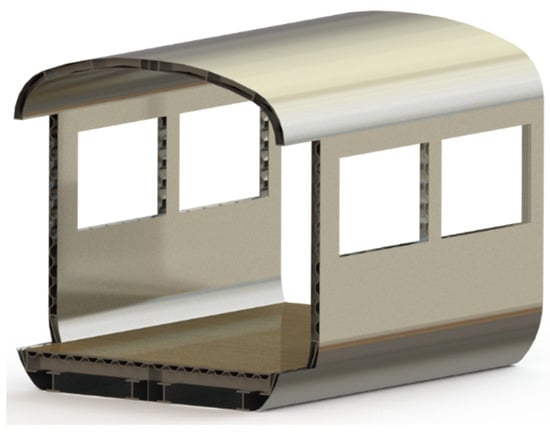
3.1. A Differential Structure of a Rail Vehicle Body
A differential structure of a passenger rail vehicle body has been utilized since the 1960s, and it still remains relevant due to its reparability and modular structure. Typically, it is produced from steel or aluminum. This approach involves joining multiple elements to create a self-supporting structure. Unlike earlier designs, which used a combination of timber and metal elements, modern differential construction utilizes steel with varying yield strengths, reaching up to 700 MPa, to enhance durability and load-bearing capacity. The key benefits include the use of standard profiles, ease of local reinforcement, and straightforward production techniques. However, the complexity of assembling numerous elements and the extensive welding requirements lead to increased production costs and the necessity for precision engineering to maintain structural integrity and resistance to fatigue.
The main advantages of the designed differential structure of a passenger rail vehicle body can be expressed as follows:
- Use of standard sheets and profiles simplifies its manufacturing;
- Ease of reparability, allowing damaged sections to be replaced independently;
- Local reinforcements can be added to increase structural strength in critical areas.
However, the designed differential structure of the wagon body also relates to certain disadvantages. They can be concluded as follows:
- High production costs due to extensive welding and additional finishing requirements;
- Outer surface irregularities that necessitate additional treatment to improve aerodynamics and aesthetics.
A differential structure of a passenger rail vehicle body and its cross-section is depicted in Figure 1.
Figure 1.
A differential structure of a passenger rail vehicle body.
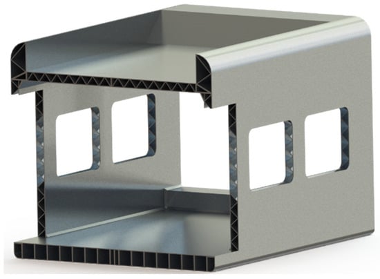
3.2. An Integral Aluminum Structure of a Rail Vehicle Body
An integral structure of a rail vehicle body features extruded aluminum profiles integrated into a single structural body. This approach to the design of a rail vehicle body structure offers reduced weight, corrosion resistance, and high structural stiffness. The manufacturing process involves precise extrusion and welding techniques, which require the use of robust jigs and automated welding systems to maintain consistency and prevent structural deformation. Despite these advantages, an integral aluminum structure design presents challenges in terms of reparability, because damaged sections cannot be easily replaced without affecting the overall integrity of the structure. In cases of major accidents, entire sections often require replacement, making maintenance both time-consuming and costly.
As in the case with the differential structure, the integral aluminum structure relates to advantages and disadvantages. The main advantages of the integral aluminum structure can be described as follows:
- Lower assembly costs due to reduced component count and an integrated structure;
- High corrosion resistance increases long-term durability in varying environmental conditions;
- A simplified installation of internal equipment due to built-in attachment points within extruded profiles.
However, the evaluated disadvantages can negatively affect the costs connected with its production and repair. Among others, the main disadvantages of the integral aluminum structure of a rail vehicle body can be described as follows:
- The high cost of extruded aluminum profiles increases initial investment requirements;
- Repair and replacement difficulties, as localized damage often necessitates the replacement of entire sections.
Figure 2 shows a three-dimensional model of an integral aluminum structure of a passenger rail vehicle body.
Figure 2.
An integral aluminum structure of a designed passenger wagon body.
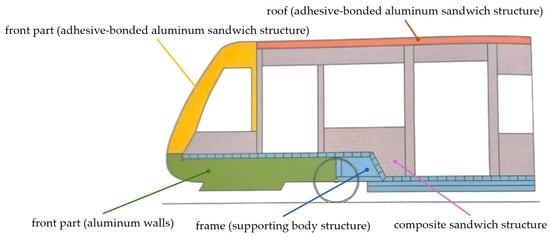
3.3. A Hybrid Structure of a Rail Vehicle Body
A hybrid structure of a rail vehicle body combines various materials to achieve a suitable balance between weight reduction and structural strength. Different materials are used for distinct components, such as composites for enclosures, aluminum for walls, and steel for load-bearing sections. This approach allows a strategic distribution of material properties, reducing overall mass while maintaining necessary strength in critical areas. The main challenge of the hybrid structure of a rail vehicle body is the complexity of joining different materials, as it requires advanced bonding techniques and consideration of differential thermal expansion properties to ensure long-term durability.
A combination of the differential and integral aluminum structure leads to the following advantages of the wagon structure:
- Reduced overall weight improves fuel efficiency and rail vehicle acceleration;
- Optimized material use for different structural elements allows for enhanced performance characteristics.
The disadvantages of the hybrid structure of a rail vehicle body are identified as follows:
- Complexity of joining different materials, requiring specialized adhesives, fasteners, and manufacturing techniques;
- Potential durability concerns due to different coefficients of thermal expansion among the materials used.
It should be explained that the improved acceleration mentioned above is achieved by the lower total weight of a rail vehicle, when the same power of a powertrain is considered.
A scheme of a hybrid structure of a passenger rail vehicle body with color-coded parts is depicted in Figure 3.
Figure 3.
A hybrid structure of a passenger rail vehicle body [49].
As described above, steel S235 as well as steel S355 and their modifications, and further, aluminum and its alloys, such as Al6061 and Al6005, are the most common materials used for a rail vehicle’s body structure production [50]. Currently, efforts in the production of lightweight structures require the application of other types of materials. These are mainly composite materials, including glass fibers, carbon fibers, aramid, and others [51]. The Škoda Transportation Inc. company [52] is known to use a hybrid structure in its products. These are mainly double-deck cars and double-deck trainsets.
An important part of the rail vehicle body is the load-bearing frame. It carries all loads arising under operational conditions, connects all components to one unit, retains structural parts of the rail vehicle in a proper position, and is a key component used to maintain the integrity of the body structure. In Section 5, three variants of rail vehicle body design are supplemented by three variants of a body frame. These frames are analyzed from the point of view of their strength.
4. Body Design of a Rail Vehicle
The superstructure design directly influences vehicle functionality, particularly in terms of accessibility, aerodynamics, and interior layout. Various enclosure designs have been analyzed in low-floor and high-floor configurations, with a focus on ensuring passenger comfort, maximizing the available space, and optimizing energy efficiency. Features such as bi-fold sliding doors, bonded windows, and integrated climate control systems contribute to operational efficiency and long-term usability.
4.1. A Door System and Accessibility
Bi-fold sliding doors facilitate passenger entry and exit while ensuring efficient space utilization. These doors operate by extending slightly from the sidewall before sliding parallel to the vehicle body, ensuring minimal intrusion into the passenger area. Their design considers thermal insulation and noise reduction, and safety requirements, door positioning, and the inclusion of easy-to-access activation buttons have been standardized to enhance accessibility and to accommodate passengers with reduced mobility.
Depending on a type of door, the following minimal dimensions must be maintained:
- The height must be at least 1950 mm for all doors;
- A minimal width of 650 mm must be set for single-leaf doors;
- A width of 1300 mm is usually set for double-leaf doors.
4.2. Window Technologies and Thermal Comfort
Windows in rail vehicles play a crucial role in noise insulation and temperature regulation. Modern designs incorporate bonded double-glazed windows, which improve durability, minimize condensation of water, and enhance structural stiffness. However, while these windows offer aesthetic and functional benefits, their replacement is more challenging compared to traditional rubber-mounted alternatives. The incorporation of frit patterns around window perimeters serves to distribute thermal stress and protect adhesives from ultraviolet degradation, extending the operational lifespan of the glazing system.
4.3. Air Conditioning and Passenger Comfort
Air-conditioning systems are essential for maintaining a comfortable passenger environment. Integrated air-conditioning units provide a consistent temperature distribution, with separate conditioning for the driver’s compartment to ensure the most suitable working conditions. A placement of air-conditioning units affects maintenance requirements, as roof-mounted systems generally experience lower dust accumulation compared to under-floor installations, which require more frequent filter replacements.
5. Variants of a Designed Rail Vehicle Body
Three specific rail vehicle body structures have been examined, each varying in floor configuration and structural layout. These designs demonstrate differing allocations of a space for seating passengers, bicycle storage, and accessibility features. Aerodynamic considerations have been incorporated into more recent models to enhance energy efficiency and reduce operational costs. Additionally, the structural stiffness of these enclosures has been optimized to minimize vibrations and improve crashworthiness.
Seats and Their Arrangement
Seats are one of the most important elements in a vehicle interior. Therefore, they are compared with requirements in terms of comfort, ergonomics, and accessories.
For regional vehicles, the best option seems to be to use a seating arrangement behind each other, the so-called aircraft seating.
The advantages of this seating arrangement are as follows:
- More privacy;
- The passenger has their own folding table, which is not shared with a seatmate;
- A better ratio of knee space comfort to seat pitch (better than a facing seat arrangement);
- A greater number of seats for a given surface area than a facing seat arrangement.
For seats on regional trains, there must be at least one 230 V socket per pair of seats.
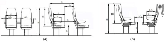
The seat pitch is determined by the UIC standard [53], which is often circumvented but has changed during its validity. For second class, the seat pitch was reduced from 850 mm to 800 mm, 760 mm, or 730 mm. The number of seats and thus also the seat pitch is determined by the customer. Figure 4 depicts the basic dimensions and distances of seats in a passenger rail vehicle body.
Figure 4.
Seating arrangements: (a) behind each other; (b) an opposite seating arrangement.
The marked dimensions and distances in Figure 4a are as follows: S—the distance between backrests, D—the distance between a backrest and a cushion, a—the length of a cushion, LA—the length of an armrest, K—the distance between the rear part of a backrest and the front part of the backrest of the following seat, h—the highest point of a cushion from the body floor, H1—the effective height of a backrest, H—the highest point of a backrest, d—the effective width of a backrest, ABr—the width of an armrest, AB1—the distance of two adjacent seats. In principle, the dimensions marked in Figure 4b are almost the same. However, in this case, dimension D indicates the distance between two seats facing each other.
6. Designs of a Passenger Wagon Body
Three variants of the enclosures are presented in this research. It should be noted that this is a design proposal based on a vehicle length of 16,500 mm, wheelbase of 9000 mm, width of 3000 mm, and height of 3500 mm. In this case, no consideration was given as to whether the body would meet the crash requirements [34,53,54,55,56]. A structural outline of the proposed vehicles was not checked in this study. However, three versions of the rail vehicle body frame as the main load-bearing structure were modelled and subsequently analyzed regarding their strength properties.
6.1. A Wagon Body Design, the First Variant
The first variant of the rail vehicle body design is shown in Figure 5a. This is a vehicle for a two-way operation. A counter-slip is implemented in the bumpers. It is possible to see them in Figure 5b.
Figure 5.
The 1st variant of the rail vehicle body design: (a) a side view; (b) a front view.
In this case, fixed windows with a hinged upper part have been fitted. It can be seen that the rail vehicle body is partially low-floor. In the low-floor part, there is a dedicated space for bicycle storage as well as space for passengers with reduced mobility and space for a stroller.
There is also a dedicated space for a toilet that is accessible for people with reduced mobility. There are seats for passengers in this area. The passengers’ seats and the driver’s position are located in the high-floor section, which is separated from the passenger compartment by partitions and doors. Bogies will be placed underneath the high-floor section. A space for vehicle equipment is reserved on the roof of the vehicle. When space conditions would permit, the internal combustion engine and traction generator would also be located on the roof of the vehicle. However, from a structural point of view, this would be a very difficult location, as the vibrations generated, primarily by the operation of the combustion engine, would be transmitted throughout a rail vehicle body structure, resulting in a significant reduction in the passengers’ ride comfort in the vehicle. These vibrations should be eliminated. The elimination of aggregated vibrations throughout the rail vehicle will be performed by means of rubber silentblocks. These components minimize amplitudes and absorb oscillations of components by their elasticity [57,58]. In special cases, hydraulic dampers to minimize oscillation frequencies will be applied between the rail vehicle body and bogies. Moreover, it is considered that components generating vibrations (a drivetrain system) will be mounted under the high floor.
6.2. A Design of the Wagon Body Frame, the First Variant
The study involved designing a passenger car frame. The method of contour superposition was used. The essence of this method is that the frame of an existing passenger car frame is projected onto a horizontal plane in the form of a rod system. Then, the internal force factors that arise in the rod system from the action of an external load are calculated. The frame execution profiles are selected based on the force factors found. Three frame execution options are considered.
The frame of a passenger car made according to the first variant is depicted in Figure 6. The frame rod system of the first variant frame is shown in Figure 7a. The calculation of internal force factors in the rod system was carried out for the case of its perception of a vertical load (Figure 7b). The value of the vertical load is taken to be equal to the value 26.5 tons, i.e., the same as in the prototype. The calculation was carried out in the software package “Lira-SAPR”. The system was secured at the support points on the bogies. The calculation results are shown in Figure 8a. The maximum value of the bending moment in the frame structure occurs in the support zones, and its value is 32.3 kN∙m. This bending moment has a negative value.
Figure 6.
A three-dimensional model of a passenger car frame—the first variant.
Figure 7.
The first variant of the passenger car body frame: (a) a rod system; (b) a calculation scheme.
Figure 8.
The first variant of the passenger car body frame: (a) a bending moment diagram of the frame (kN∙m); (b) a displacement diagram of the frame; the scale is 30:1.
Figure 8b shows the diagram of the frame displacements on an enlarged scale. That is, the maximum displacements occur in the end parts of the frame. This can be explained by the frame fastening scheme and its loading.
A selection of frame profiles was carried out based on the moment of resistance W. The following formula was used:
where M is the bending moment of the frame section; [σ] is the permissible stress of the frame structure material.
It is considered that the frame is made of 09G2S steel. The permissible stresses are 210 MPa for this steel. Then, the value of the moment of inertia is W = 153.8 cm3.
Analyzing the range of existing profiles for manufacturing the passenger car frame, it is proposed to use a 180 × 180 mm square tube with a wall thickness of 4.5 mm as a frame profile. The mass of 1 m of this tube is 24.39 kg.
The use of this profile can be justified not only by the manufacturability of the frame, but also by the fact that at subsequent stages of the calculation it is possible to consider the introduction of energy-absorbing material as a filler for such a tube. This will reduce the stresses in the frame under operational loading schemes.
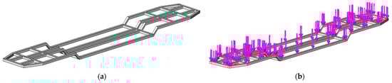
A spatial model of the first variant frame was created (Figure 9a) to study its strength. Calculations were carried out using the finite element method in the SolidWorks Simulation 2018 software package. In this case, the von Mises criterion was applied. This is justified by the fact that material of the frame structure is steel. It has isotropic properties.
Figure 9.
A frame of the passenger car body, the first variant: (a) a spatial model; (b) a calculation scheme.
A design scheme of the frame is shown in Figure 9b. It is considered that the structure is loaded by the vertical loads. These loads are marked by the vertical arrows (Figure 9b). The model is supported in those areas where the frame rests on the bogies (couplings of boundary conditions).
The finite element model is formed by tetrahedrons and contains 83,240 elements and 163,928 nodes. The finite element model of the first variant of the frame is depicted in Figure 10a, and the most loaded areas are depicted in Figure 10b. The maximum element size is 85 mm, and the minimum is 4.25 mm.
Figure 10.
(a) A finite element model of the first frame variant; (b) the most loaded areas of the 1st frame variant.
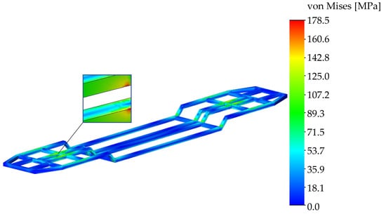
The calculation results showed that the maximum stresses occur in the central longitudinal beams (Figure 11), i.e., in the zones of their interaction with the center plates. The value of these stresses is 178.5 MPa (Figure 11).
Figure 11.
A distribution of stresses in the first frame variant.
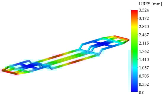
These stresses are 15% lower than the permissible ones. It is important to note that the frame structure will have greater stiffness in a real operation than in these calculations, because it is compacted from above by a floor covering with supporting elements. Therefore, the stresses in it will have lower values. The maximal deflections occur in the longitudinal beams of the frame, and they are 3.5 mm (Figure 12).
Figure 12.
Deflections in nodes of the first frame variant.
It should be noted that the weight of this frame is 4.1 tons, which is lower by almost 2% than the existing design.
6.3. A Wagon Body Design, the Second Variant
Figure 13 shows the second variant of a passenger rail vehicle body. This is also a low-floor vehicle. However, the proportion of the low floor would be considerably less, as the vehicle’s armament would be located under the floor in the high-floor section.
Figure 13.
The second variant of the rail vehicle body design: (a) a side view; (b) a front view.
The low-floor section has a dedicated space for bicycle storage, and, of course, a space for passengers with reduced mobility, and a space for one pushchair. There is also a dedicated space for a toilet as well as for passengers’ seats. The passengers’ seats and the driver’s station are located in the high-floor section, which is separated from the passenger compartment by partitions and doors. The engine with a traction generator would be housed in what is known as a railpack, which is essentially a structure with an engine mounted using rubber silentblocks. The design of the rail vehicle is embellished with a light strip that is placed on the edges of the front parts of the vehicle. The frontal surface is non-typical. A reinforced structure designed to preserve the survival space for a driver in the case of a collision is located behind the light strip. There is also a counter-slip mechanism behind the body of the light strip. The vehicle is capable of bi-directional operation. An air-conditioning unit is located at the bottom of the vehicle, which has the disadvantage of clogging the cabin filter more frequently compared to the location on the vehicle’s roof. The vehicle is fitted with large fixed glued windows, which have the disadvantage of being costly to replace when they are broken. However, these windows fulfil an aesthetic function, and they allow a better view for passengers. These windows also fulfil the required strength criteria.
6.4. A Design of the Wagon Body Frame, the Second Variant
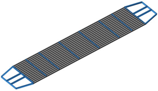
At the next stage of the study, the calculation of the vehicle frame formed by horizontal rods was carried out (Figure 14). A rod model of the frame was created (Figure 15a) in order to determine the internal force factors. A calculation scheme of the frame is shown in Figure 15b. The value of the vertical load is considered to be 24.8 tons. The frame fastening is identical to that used for the scheme in Figure 7.
Figure 14.
A three-dimensional model of a passenger car frame—the second variant.
Figure 15.
The second variant of the passenger car body: (a) a rod system; (b) a calculation scheme.
The calculation results are shown in Figure 16a. The maximum bending moment occurs in the areas where the structure is mounted on the bogies, and it is of 36.8 kN∙m. The frame deflection diagram is shown in Figure 16b. The maximal deflections occur in the cantilever parts of the frame. This is explained by the load diagram applied to it, as well as its fastening.
Figure 16.
The second variant of the passenger car body: (a) a bending moment diagram of the frame (kN∙m); (b) a deflection diagram of the frame; the scale is 30:1.
It is proposed to use square tubes with the dimensions of 180 × 180 mm and with a wall thickness of 4.5 mm as the profiles for the longitudinal and transverse beams, based on the obtained results. It is considered that intermediate longitudinal beams in the form of steel sheets with a height of 180 mm and a thickness of 4 mm will be created. Considering this fact, a spatial model of the frame is set up as is shown in Figure 17a.
Figure 17.
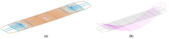
The frame of the passenger car body, the second variant: (a) a spatial model; (b) a calculation scheme.
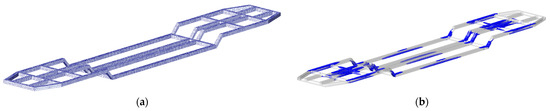
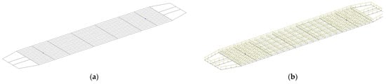
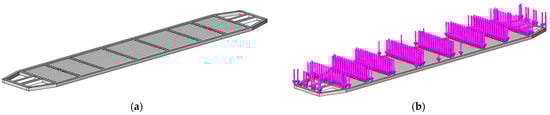
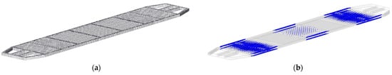
The load scheme of the second variant of the frame is shown in Figure 17b. The fastening scheme (i.e., boundary conditions) is identical to the previous design scheme of the frame. The finite element model of the frame includes 104,392 elements and 211,605 nodes (Figure 18a). The most loaded areas of the second variant of the body frame are depicted in Figure 18b.
Figure 18.
(a) A finite element model of the second frame variant; (b) the most loaded areas of the second frame variant.
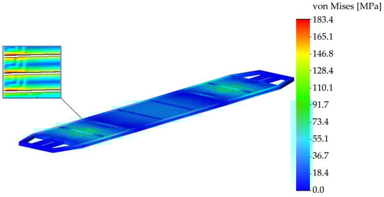
The calculation results are shown in Figure 19 and Figure 20. The most loaded zones of the frame are shown in Figure 20. These most loaded zones occur in locations of the second variant of the frame where the frame is supported on the bogies, as well as the central parts of the longitudinal beams.
Figure 19.
A distribution of stresses in the second frame variant.
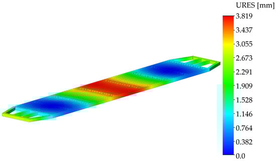
Figure 20.
Deflections in nodes of the second frame variant.
The maximum stresses occur in the areas of the frame where the frame rests on the bogies, and they amount to 183.4 MPa (Figure 19). These stresses are 12.7% lower than the permissible stresses. The maximum displacements occur in the central part of the frame, and they are of 3.8 mm (Figure 20). The mass of this frame design is 3.95 tons, which is lower by 1.6% than the mass of a prototype.
6.5. A Wagon Body Design, the Third Variant
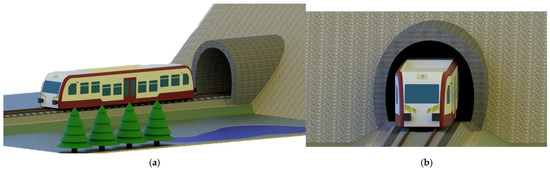
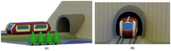
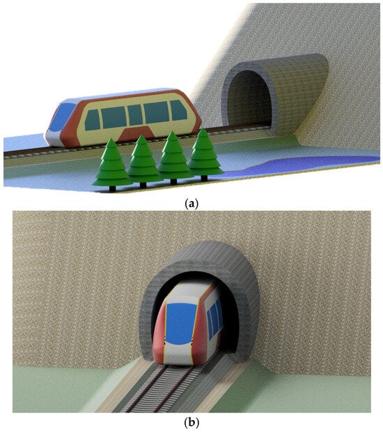
Figure 21 shows a study of the third variant of a passenger car. It is created with the aim of minimizing aerodynamic drag. The better aerodynamic properties allow it to have lower aerodynamic drag at higher running speeds, which will result in lower fuel consumption, together with lower operating costs.
Figure 21.
The third variant of the rail vehicle body design: (a) a side view; (b) a front view.
At the same time, better aerodynamics allows for the reduction of aerodynamic drag, together with better running properties, in a tunnel, reducing vehicle noise and vibration. The low-floor section has a space for bicycle storage as well as a space for passengers with reduced mobility and a space for a stroller and passengers’ seats. The high-floor section houses the passengers’ seats and the driver’s position, which is also separated from the passenger compartment by partitions and doors. There is no toilet in this variant due to the increase in the passenger capacity. There is an exception in this case, that the distance of the bogies has been moved by one meter for a total length of 10 m. This provides a higher proportion of a low-floor space. An internal combustion engine with a traction generator in a railpack would be located under the high floor. The remaining accessories would also be located under the high floor. The vehicle is capable of operating in both directions.
6.6. A Design of the Wagon Body Frame, the Third Variant
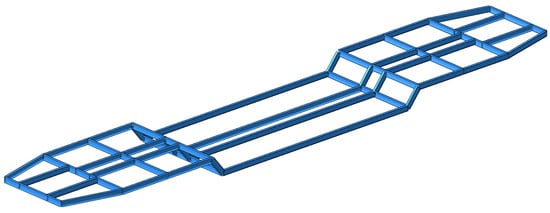
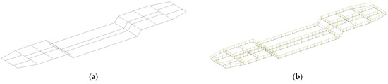
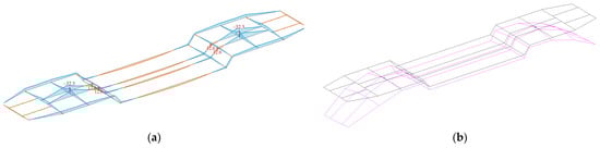
The calculation was also performed for the third variant of the frame. The frame design is identical to the second variant of the frame shown in Figure 17a. However, the vertical load acting on the third variant of the frame is 21.9 tons. Hence, the bending moment diagram has the form shown in Figure 22a. The maximum bending moment occurs in the areas where the structure rests on the bogies. Its value is 31.8 kN∙m (Figure 22b).
Figure 22.
The third variant of the passenger car frame: (a) a bending moment diagram of the frame (kN∙m); (b) the most loaded areas of the frame.
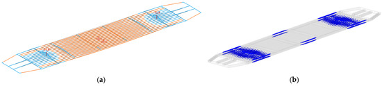
Square tubes with the dimensions of 180 × 180 mm and with a wall thickness of 4.5 mm are used as profiles for the longitudinal and transverse beams, considering the found value of the bending moment, i.e., as in the previous version of the frame design (the second frame variant). It is proposed to make intermediate longitudinal beams in the form of steel sheets with a height of 180 mm and a thickness of 3.2 mm. The corresponding calculations were carried out to analyze the strength of such a frame structure. The structure of the frame is similar to the frame variant shown in Figure 18a. The finite element model of the frame includes 102,187 elements and 203,455 nodes.
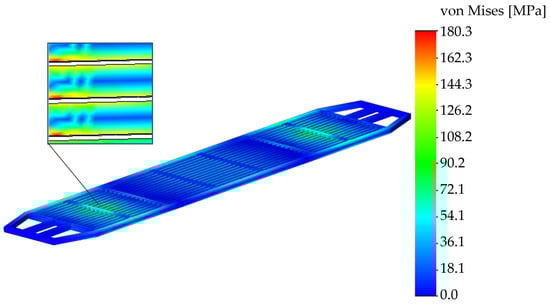
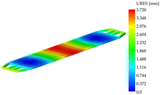
It was found that the maximum stresses occur in the areas where the frame is mounted on the bogies, as well as in the central parts of the longitudinal beams (Figure 22b). These stresses are equal to the value of 180.3 MPa (Figure 23), and they are 14% lower than the permissible values. The maximal deflections occur in the central part of the frame, and they are equal to the value of 3.7 mm (Figure 24). The weight of this frame structure (the third frame variant) is 3.88 tons. It is lower by 1.7% than the prototype.
Figure 23.
A distribution of stresses in the third frame variant.
Figure 24.
Deflections in nodes of the third frame variant.
7. An Interior Arrangement
Two interior designs were made for each variant, which are shown in figures below. There is also a table showing the number of seats and standing places. Four passengers per 1 m2 were considered for the calculation of standing places.
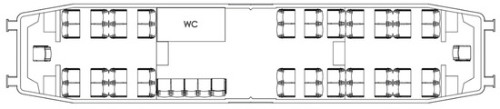
Figure 25 shows the design of an interior layout, No. 1, in the first variant of the rail vehicle body. There is a large toilet for passengers, including passengers with reduced mobility, at the boarding door. There is a trio of full-size seats opposite the lavatory. There are two folding seats next to them with a space for people with reduced mobility or a place for a stroller. There are also holders for putting away a bicycle. The seat track is 760 mm in a facing configuration and 380 mm in a rearward configuration. The shelves located above the seats can be used to store luggage. For heavy luggage, the space is reserved between the seats, which are facing each other, or in the space under the seats.
Figure 25.
The variant No. 1 of the interior arrangements.
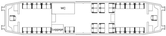
Figure 26 shows an interior layout, No. 1-1, also belonging to the first variant of the rail vehicle body design. The number of seats is reduced compared to the previous interior layout. However, the area for standing passengers has been considerably increased. The toilet is the same, but there is a rack for stowing heavy luggage instead of seats. A pair of folding seats with space for a pushchair, mobility-impaired passengers, and a bicycle rack is next to the rack. A space between the seats has been retained as in the previous interior layout.
Figure 26.
The interior arrangements of variant No. 1-1.
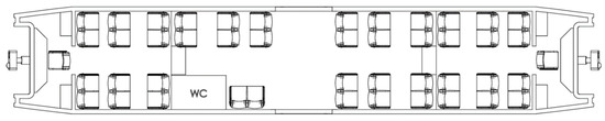
The interior layout No. 2, shown in Figure 27, is for the second variant of the rail vehicle body. The seat pitch is identical to the previous seat pitch. A toilet is located in the low-floor section, which is not accessible for wheelchair users due to dimensional reasons. A pair of folding seats with a space for a pushchair, wheelchair users, and a bicycle storage system is located next to the toilet. A storage shelf for luggage is located above the seats.
Figure 27.
The interior arrangements of variant No. 2.
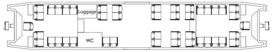
The conditions of variant No. 2-1, presented in Figure 28, are the same as in the previous design. The difference consists in the fact that the pair of seats opposite the toilet is not placed there, in favor of a luggage rack.
Figure 28.
The interior arrangements of variant No. 2-1.
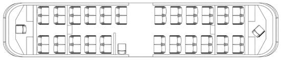
For the last variant, No. 3, of the enclosure, the layout was aimed at the highest possible passenger capacity, as is shown in Figure 29. For this reason, the toilet has been omitted, which can be evaluated as a discomfort for passengers. There is one folding seat at the boarding door, with space for a wheelchair, a carriage, and a bicycle stowage system. The seating arrangement is in airplane style. This means that there is an effort to maximize the seated passenger capacity. The area for standing passengers has been considerably reduced. The space for standing passengers is essentially just an aisle and a boarding area. In this case, shelves above the seats are used to store the luggage.
Figure 29.
The interior arrangements of variant No. 3.
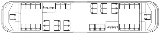
A different interior layout, No. 3-1, of the third variant of the rail vehicle body is shown in Figure 30. Compared to the first design (Figure 25 and Figure 27), the seating arrangement has changed considerably. A pair of luggage racks has been added. The number of seats has been considerably reduced, but the area for standing passengers has been increased. There is also a possibility that there would be one storage rack, and a small toilet would be fitted instead of the second one. However, this small toilet would not have a sufficient area for wheelchair users to enter. A comparison of the passengers’ capacity is presented in Table 1.
Figure 30.
The interior arrangements of variant No. 3-1.

Table 1.
Capacity of passengers in each variant.
8. Discussion of the Research
The results of the research can be concluded as a design proposal for a passenger rail vehicle body, which is intended to be used for modern passenger transportation, mainly in urban areas. Three different passenger rail vehicle body designs have been created, namely a differential, an integral, and a hybrid structure. Each of them has advantages and disadvantages, which are listed in Table 2.
Table 2.
A list of advantages and disadvantages of different passenger rail vehicle body designs.
The differential structure of a vehicle body is a traditional design, and it is used for bodies made of steel. A skeleton is covered by steel sheets, and these components are welded to each other. Relatively high production costs and difficult technology make it an outdated structure type. The integral structure of a rail vehicle body is much easier for manufacturing in comparison with the differential structure. Extruded profiles of the integrated structure do not need additional straightening, and the use of aluminum profiles improves its corrosion resistance. There is also a proposal to use a hybrid passenger rail vehicle structure. It combines the advantages of the differential and integral structure, in which composite materials are included. They improve the strength of the most exposed parts of the body, reduce the total weight of the structure, and contribute to long-term corrosion resistance of vehicle body parts.
Six variants of interior layouts of a vehicle body were created. These layouts differ in their internal arrangements, for which interior equipment was important. As can be concluded, the modern design of a rail vehicle also means an application of innovative production methods. The newest research has shown that 3D printing helps to produce vehicles with acceptable costs [59,60]. It can also be assumed that new production technologies can be applied in the production of newly designed railway vehicles [61,62,63]. As is stated in the research [64] and in other work [65], the structural integrity and life assessment of rail vehicles’ components are critical for the safety and challenges faced, including high production and processing costs, durability issues in harsh railway environments, and environmental impacts associated with alloy production. Research findings indicate that innovative alloys and advanced processing techniques, such as powder metallurgy, additive manufacturing, and surface treatment, significantly improve the applicability of titanium alloys in railway applications. Three-dimensional printing and additive manufacturing technologies are already used by the DB company and the Siemens Mobility company to manufacture spare parts of rail vehicles’ components, such as a gearbox or components for interiors [66,67]. Other leading global companies using additive technologies are SNCF, Renfe, CAF, OBB, Angle Trains, Wabtec, Pesa, Newag, and others. These companies have applied state-of-the-art production technologies, mainly during maintenance processes, and they have achieved strong time savings (over 80%), together with lower production costs. A list of rail vehicles’ components manufactured by means of additive technologies includes external parts of vehicles, such as air ducts, cable holders, housings, handrails, armrests, grab handles, seat-back tables, wheelset bearing covers, and others. Additionally, metal additive technologies are applied for manufacturing engine control chassis, sand pipes for the traction system of rail vehicles (i.e., locomotives), brake control panels, and similar applications [68]. It is important to note that the safety standards for all components must be considered [34,35,36].
Further, three variants of the passenger rail vehicle body have been created in 3D CAD software. These frames are formed by profile elements. Proper dimensions of the profile elements were found by means of a specialized software, Lira-SAPR. Subsequently, the designed frames were analyzed from the point of view of their strength. The finite element method was applied for the strength analyses. The results of the strength analyses of all three variants of the body frames showed that the maximal stresses identified in the structures did not exceed the values of the permissible stresses. The first variant of the body frame had a maximal stress of 178.5 MPa and a maximal deflection of 3.5 mm, and the total weight was reduced by 2%. In case of the second variant of the rail vehicle body frame, the maximal stress was 183.4 MPa, the maximal deflection was 3.8 mm, and the weight was lower by 1.6%. Finally, the third variant of the frame had a maximal stress of 180 MPa and a maximal deflection of 3.7 mm. The total weight was lower by 1.7%. As can be seen, the maximal stresses as well as the maximal displacements for all three variants of the rail vehicle body frames were very similar. The first variant of the body frame is the most suitable due to its having the lowest values of the observed quantities. Its reliability and the long-term operation of the vehicle can be assumed.
The future research in this area will be focused on the evaluation and assessment of the dynamic properties of the designed passenger rail vehicle. It is assumed that a bogie structural unit will also be created. Simulation analyses will be employed for these purposes. As current developments in the field of power sources are focused on using renewable and green energy sources, it is assumed that the designed passenger rail vehicle would be powered by an alternative source of power instead of a conventional powertrain. This would relate to the vehicle with an independent traction system. The latest research and scientific activities, together with the research activities of rail vehicle producers, involve the application of hydrogen as a power source [69,70,71,72]. Time will reveal which alternative source of power will be the best choice for modern railway passenger transport.
9. Conclusions
The choice of rail vehicle body design is a critical factor in optimizing performance, maintenance, and passenger comfort. A differential body structure offers robust repairability and an extensive use of standardized materials; an integral aluminum body structure provides lightweight efficiency and corrosion resistance; and a hybrid body structure strategically combines materials to balance performance and weight reduction. Future advances in materials science and manufacturing techniques, such as the increased use of composite materials and additive manufacturing technologies, will further influence the design of rail vehicles, with an emphasis on sustainability, reduced life cycle costs, and increased structural durability. Three passenger rail vehicle body variants were proposed using differential and integral structures, together with incorporating a high proportion of comfort features. The rail vehicle bodies were created based on the basic dimensions that need to be maintained. The main limit of the rail vehicle body was the need to maintain a low floor section, which is influenced by the wheelbase and the location of other vehicle components. The distance of the bogies was lengthened for the third variant of the rail vehicle body structure. This has a positive effect on the dimensions of the low-floor section. In addition to the passenger rail vehicle body design, three variants of body frames were created. These frames are the main load-bearing structure of the passenger rail vehicle body. Therefore, they have also been analyzed from the point of view of their strength. The strength analyses were performed by means of the finite element method. It was discovered that the designed body frames meet the strength criteria. The design of the seating layout has six variants, focusing on maximum carrying capacity and the presence or absence of a toilet, which affects the comfort of passengers, and different arrangements of luggage space.
Author Contributions
Conceptualization, M.B. (Martin Bučko), D.B., A.L. and D.B.; methodology, M.B. (Martin Bučko), D.B., M.B. (Miroslav Blatnický) and J.D.; software, M.B. (Martin Bučko), A.L., M.B. (Miroslav Blatnický) and M.P.; validation, D.B., M.B. (Miroslav Blatnický) and J.D.; formal analysis, A.L., J.D. and M.B. (Miroslav Blatnický); investigation, M.B. (Martin Bučko), D.B. and M.P.; resources, A.L., J.D. and M.B. (Miroslav Blatnický); data curation, M.B. (Martin Bučko), D.B., M.B. (Miroslav Blatnický) and M.P.; writing—original draft preparation, M.B. (Martin Bučko) and J.D.; writing—review and editing, D.B., A.L. and J.D.; visualization, M.B. (Martin Bučko), M.B. (Miroslav Blatnický) and M.P.; supervision, D.B., A.L. and J.D.; project administration, A.L. and J.D.; funding acquisition, A.L. and J.D. All authors have read and agreed to the published version of the manuscript.
Funding
This publication was supported by the Cultural and Educational Grant Agency of the Ministry of Education of the Slovak Republic for the project KEGA 031ŽU-4/2023: Development of key competencies of the graduates of the study program Vehicles and Engines. This research was also supported by the Slovak Research and Development Agency of the Ministry of Education, Science, Research and Sport of the Slovak Republic, VEGA 1/0308/24 “Research of dynamic properties of rail vehicle mechanical systems with flexible components when running on a track.” “Funded by the EU NextGenerationEU under the Recovery and Resilience Plan for Slovakia under the project No. 09I03-03-V01-00131”.
Institutional Review Board Statement
Not applicable.
Informed Consent Statement
Not applicable.
Data Availability Statement
The data is contained within the article.
Conflicts of Interest
The authors declare no conflicts of interest.
References
- Alic, D.; Miltenovic, A.; Banic, M.; Zafra, R.V. Numerical investigation of large vehicle aerodynamics under the influence of crosswind. Spectr. Mech. Eng. Oper. Res. 2025, 1, 13–23. [Google Scholar] [CrossRef]
- Liu, H.; Li, X.; Shi, Z.; Zhu, Y.; Luo, Y. Research on aerodynamic shape optimization of high-speed urban EMU with full tunnel. J. Railw. Sci. Eng. 2023, 20, 1180–1188. [Google Scholar]
- Mikhailov, E.; Semenov, S.; Sapronova, S.; Tkachenko, V. On the issue of wheel flange sliding along the rail. In Proceedings of the 11th International Conference Transbaltica, Vilnius, Lithuania, 2–3 May 2019. [Google Scholar]
- Lack, T.; Gerlici, J. The FASTSIM method modification to speed up the calculation of tangential contact stresses between wheel and rail. Manuf. Technol. 2013, 13, 486–492. [Google Scholar] [CrossRef]
- Mikhailov, E.; Gerlici, J.; Kliuiev, S.; Semenov, S.; Lack, T.; Kravchenko, K. Mechatronic system of control position of wheel pairs by railway vehicles in the rail track. In Proceedings of the 17th International Scientific Conference on Dynamics of Rigid and Deformable Bodies 2019, Usti nad Labem, Czech Republic, 9–11 October 2019. [Google Scholar]
- Semenov, S.; Mikhailov, E.; Dizo, J.; Blatnický, M. The research of running resistance of a railway wagon with various wheel designs. In Lecture Notes in Intelligent Transportation and Infrastructure, Proceedings of the TRANSBALTICA XII: Transportation Science and Technology, Vilnius, Lithuania, 16–17 September 2021; Springer: Berlin, Germany, 2021; pp. 110–119. [Google Scholar]
- Fischer, S. Investigation of the settlement behavior of ballasted railway tracks due to dynamic loading. Spectr. Mech. Eng. Oper. Res. 2025, 2, 24–46. [Google Scholar] [CrossRef]
- Bryk, K.; Urbański, P.; Gallas, D.; Tarnawski, P.; Michalak, P.; Stobnicki, P. Simulation analysis of an electric multiple unit vehicle energy consumption. In Proceedings of the SAE 2022 Powertrains, Fuels and Lubricants Conference and Exhibition, PFL 2022, Krakow, Poland, 6–8 September 2022. [Google Scholar]
- Olojede, O.A.; Folorunso, S.A.; Popoola, A.S.; Oladeji, P.B.; Akintifonbo, O.; Odeyemi, D.J. Passengers’ satisfaction with the Lagos shuttle train services, Lagos, Nigeria. Sci. J. Silesian Univ. Technology. Ser. Transp. 2023, 120, 215–231. [Google Scholar] [CrossRef]
- Akgun, N.; Campisi, T.; Sunar, M.T. Generalized ordered logit model with testing assumptions: A case study of using urban light rail in Bursa. Commun. Sci. Lett. Univ. Žilina 2024, 26, D38–D51. [Google Scholar] [CrossRef]
- Kučera, P.; Heřmánková, A. The use of automation in rail transport to ensure interchanges in regional passenger transport. Commun. Sci. Lett. Univ. Žilina 2024, 26, D82–D91. [Google Scholar] [CrossRef]
- Donohue, B.P. Review of passenger railroad emu and mu rolling stock in the US and Canada Part I, New York state region. In Proceedings of the 2024 Joint Rail Conference, JRC 2024, Columbia, SC, USA, 13–15 May 2024. [Google Scholar]
- Gerlici, J.; Lovska, A.; Kozáková, K. Research into the longitudinal loading of an improved load-bearing structure of a flat car for container transportation. Designs 2025, 9, 12. [Google Scholar] [CrossRef]
- Gerlici, J.; Lovska, A.; Pavliuchenkov, M. Study of the dynamics and strength of the detachable module for long cargoes under asymmetric loading diagrams. Appl. Sci. 2024, 14, 3211. [Google Scholar] [CrossRef]
- Stoica, M.; Cucu, L. Economic Analysis of a modular storage system designed for railway industry use. In Proceedings of the 1st International Conference on Innovation in Engineering, ICIE 2021, Guimarães, Portugal, 28–30 June 2021. [Google Scholar]
- Fischer, S.; Kocsis Szürke, S. Detection process of energy loss in electric railway vehicles. Facta Univ. Ser. Mech. Eng. 2023, 21, 81–99. [Google Scholar] [CrossRef]
- Meilus, L.; Maskeliūnaitė, L.; Sivilevičius, H. Economical comparison of passenger rail traction rolling stock alternatives. In TRANSBALTICA XV: Transportation Science and Technology, Proceedings of the 15th International Conference TRANSBALTICA, Vilnius, Lithuania, 19–20 September 2024; Springer: Cham, Switzerland, 2025; Pt F230, pp. 423–435. [Google Scholar]
- Sievi, A.; Brick, H.; Rüst, P. Structure-borne noise contributions on interior noise in terms of car design and vehicle type. In Noise and Vibration Mitigation for Rail Transportation Systems, Proceedings of the 13th International Workshop on Railway Noise, Ghent, Belgium, 16–20 September 2019; Springer: Cham, Switzerland, 2021; Volume 150, pp. 167–175. [Google Scholar]
- Tiwari, V.; Sharma, S.C.; Harsha, S.P. Ride comfort analysis of high-speed rail vehicle using laminated rubber isolator based secondary suspension. Veh. Syst. Dyn. 2023, 61, 2689–2715. [Google Scholar] [CrossRef]
- Palomares, E.; Morales, A.L.; Nieto, A.J.; Felix, M.; Chicharro, J.M.; Pintado, P. Is the standard ride comfort index an actual estimation of railway passenger comfort? Veh. Syst. Dyn. 2023, 61, 2811–2824. [Google Scholar] [CrossRef]
- Banić, M.; Pavlović, I.R.; Miltenović, A.; Simonović, M.; Mladenović, M.; Jovanović, D.; Rackov, M. Prediction of dynamic response of vibration isolated railway obstacle detection system. Acta Polytech. Hung. 2022, 19, 51–64. [Google Scholar] [CrossRef]
- Petrović, A.D.; Banić, M.; Simonović, M.; Stamenković, D.; Miltenović, A.; Adamović, G.; Rangelov, D. Integration of computer vision and convolutional neural networks in the system for detection of rail track and signals on the railway. Appl. Sci. 2022, 12, 6045. [Google Scholar] [CrossRef]
- Tomaschek, T.A.; Selmeczy, A.M. Mobility data for a safer and greener transport. Acta Tech. Jaur. 2023, 16, 129–142. [Google Scholar] [CrossRef]
- Rosin, C.; Sineau, M.; Regairaz, J.-P.; Cordoliani, T. Railway noise monitoring—A tool to analyse in detail the evolution of noise over time. In Proceedings of the 10th Convention of the European Acoustics Association, EAA 2023, Torino, Italy, 11–15 September 2023. [Google Scholar]
- Lovska, A.; Stanovska, I.; Nerubatskyi, V.; Hordiienko, D.; Zichenko, O.; Karpenko, N.; Semenenko, Y. Determining features of the stressed state of a passenger car frame with an energy-absorbing material in the girder beam. East.-Eur. J. Enterp. Technol. 2022, 5, 44–53. [Google Scholar]
- Zvolenský, P.; Leštinský, L.; Dungel, J.; Grencík, J. Evaluation of acoustic parameters of air conditioning of railway passenger cars. In Proceedings of the 14th International Scientific Conference on Sustainable, Modern and Safe Transport, TRANSCOM 2021, Virtual, Slovak Republic, 26–28 May 2021. [Google Scholar]
- Ďungel, J.; Zvolenský, P.; Grenčík, J.; Leštinský, L.; Krivda, J. Localization of increased noise at operating speed of a passenger wagon. Sustainability 2021, 13, 453. [Google Scholar] [CrossRef]
- Cernusek, P.; Skvaridlo, R. Curent and future projects of single deck units from Panter′s family. In Proceedings of the 26th International Conference Current Problems in Rail Vehicles (PRORAIL), Zilina, Slovak Republic, 20–23 September 2025. [Google Scholar]
- Kundrata, M.; Tízek, J. Curent status of non-traction Skoda trainsets. In Proceedings of the 26th International Conference Current Problems in Rail Vehicles (PRORAIL), Zilina, Slovak Republic, 20–23 September 2023. [Google Scholar]
- Sindel, R. Possibilities of use battery and hydrogen vehicles. In Proceedings of the 26th International Conference Current Problems in Rail Vehicles (PRORAIL), Zilina, Slovak Republic, 20–23 September 2023. [Google Scholar]
- Šťastniak, P.; Rakár, M.; Tízek, J. Design of a height-adjustable boarding system for a new double-deck railway vehicle. Acta Mech. Autom. 2023, 17, 45–51. [Google Scholar] [CrossRef]
- Trout, S.F. Passenger railcar production in North America: Rationalization and standardization. In Proceedings of the 2024 Joint Rail Conference, JRC 2024, Columbia, SC, USA, 13–15 May 2024. [Google Scholar]
- EN 45545-1:2013; Railway Applications—Fire Protection on Railway Vehicles—Part 1: General. European Committee for Standardization: Brussels, Belgium, 2013.
- EN 15227:2020; Railway Applications—Crashworthiness Requirements for Rail Vehicles. European Committee for Standardization: Brussels, Belgium, 2020.
- EN 12663-1:2024-02; Railway Applications—Structural Requirements of Railway Vehicle Bodies—Part 1: Locomotives and Passenger Rolling Stock (and Alternative Method for Freight Wagons). European Committee for Standardization: Brussels, Belgium, 2024.
- EN 45545-2:2020+A1:2023; Railway applications. Fire Protection on Railway Vehicles Requirements for Fire Behaviour of Materials and Components. European Committee for Standardization: Brussels, Belgium, 2023.
- Schmauder, N.; Malzacher, G.; Fritsche, M.; Burkat, M.; König, J.; Boese, B. High potential: Lightweight optimised structural design of car bodies for railway vehicles with alternative drive systems. Discov. Mech. Eng. 2024, 3, 10. [Google Scholar] [CrossRef]
- Ihme, J. Rail Vehicle Technology; Springer Fachmedien Wiesbaden GmbH, Part of Springer Nature: Wiesbaden, Germany, 2022. [Google Scholar]
- Liu, C.; Ma, K.; Zhu, T.; Ding, H.; Sun, M.; Wu, P. A New Car-Body Structure Design for High-Speed EMUs Based on the Topology Optimization Method. Appl. Sci. 2024, 14, 1074. [Google Scholar] [CrossRef]
- Cascino, A.; Meli, E.; Rindi, A. A strategy for lightweight designing of a railway vehicle car body including composite material and dynamic structural optimization. Railw. Eng. Sci. 2023, 31, 340–350. [Google Scholar] [CrossRef]
- Cascino, A.; Meli, E.; Rindi, A. Dynamic size optimization approach to support railway carbody lightweight design process. Proc. Inst. Mech. Eng. Part F J. Rail Rapid Transit 2022, 237, 871–881. [Google Scholar] [CrossRef]
- Ulbricht, A.; Zeidler, F.; Bilkenroth, F.; Soltysiak, S. Structural lightweight components for energy-efficient rail vehicles using high performance composite materials. Transp. Res. Procedia 2023, 72, 1685–1692. [Google Scholar] [CrossRef]
- Cascino, A.; Meli, E.; Rindi, A. Comparative Analysis and Dynamic Size Optimization of Aluminum and Carbon Fiber Thin-Walled Structures of a Railway Vehicle Car Body. Materials 2025, 18, 1501. [Google Scholar] [CrossRef] [PubMed]
- EN 13749:2011; Railway Applications—Wheelsets and Bogies—Method of Specifying the Structural Requirements of Bogie Frames. European Committee for Standardization: Brussels, Belgium, 2011.
- Srivastava, P.K.; Simant; Shukla, S. Topology Optimization: Weight Reduction of Indian Railway Freight Bogie Side Frame. Int. J. Mech. Eng. 2021, 6, 4374–4383. [Google Scholar]
- Cascino, A.; Meli, E.; Rindi, A. Development of a Design Procedure Combining Topological Optimization and a Multibody Environment: Application to a Tram Motor Bogie Frame. Vehicles 2024, 6, 1843–1856. [Google Scholar] [CrossRef]
- Cascino, A.; Meli, E.; Rindi, A. A New Strategy for Railway Bogie Frame Designing Combining Structural–Topological Optimization and Sensitivity Analysis. Vehicles 2024, 6, 651–665. [Google Scholar] [CrossRef]
- Ulbricht, A. Rail vehicle in CFRP-intensive design. Lightweight Des. Worldw. 2019, 12, 36–41. [Google Scholar] [CrossRef]
- Bučko, M. Study of a Motor Wagon for Regional Operation with Single-Axle Bogies. Master’s Thesis, University of Žilina, Žilina, Slovakia, 2024. [Google Scholar]
- Lutema, M.E.; Temesgen, K. A Review on Static Analysis of Aluminium Carbody Structure for Passenger Trains. Int. J. Eng. Appl. Sci. 2022, 9, 1–5. [Google Scholar]
- Mistry, P.; Johnson, M.; Galappaththi, U. Selection and ranking of rail vehicle components for optimal lightweighting using composite materials. Proc. Inst. Mech. Eng. Part F J. Rail Rapid Transit 2020, 235, 390–402. [Google Scholar] [CrossRef]
- 52UIC 567-2-4ed; Standard Z-Type Coaches Accepted for Running in International Traffic—Characteristics. Union Internationale des Chemins de fer: Paris, France, 1991.
- ERA. Safety Certification 2022; ERA: Lille, France, 2022. [Google Scholar]
- European Union Agency for Railways. TSI Directive EU 2016/767 on the Interoperability of the Rail System Within the European Union; Publications Office of the European Union: Luxembourg, 2016. [Google Scholar]
- Fanta, O.; Lopot, F.; Kubovy, P.; Jelen, K.; Hymarova, D.; Svoboda, M. Kinematic Analysis and Head Injury Criterion in a Pedestrian Collision with a Tram at the Speed of 10 and 20 km.h−1. Manuf. Technol. 2022, 22, 139–145. [Google Scholar] [CrossRef]
- Damjanović, M.; Stević, Ž.; Sranimirović, D.; Tanackov, I.; Marinković, D. Impact of the number of vehicles on traffic safety: Multiphase modeling. Facta Univ. Ser. Mech. Eng. 2022, 20, 177–197. [Google Scholar] [CrossRef]
- Wang, W.; Song, C.; Li, X. Finite element simulation analysis of static stiffness of bushing rubber mount. In Proceedings of the 3rd International Conference on Advanced Manufacturing Technology and Manufacturing Systems, ICAMTMS 2024, Changsha, China, 24–26 May 2024. [Google Scholar]
- Zeng, X.; Xu, J.; Wang, X.; Yang, X.; Yang, C. Working mechanisms and dynamic performances for a hydraulically damped bushing with an inertia track. Proc. Inst. Mech. Eng. Part D J. Automob. Eng. 2024, 238, 4338–4346. [Google Scholar] [CrossRef]
- Brodsky, J. Application of 3D print in the construction of rail vehicles. In Proceedings of the 26th International Conference Current Problems in Rail Vehicles (PRORAIL), Zilina, Slovak Republic, 20–23 September 2025. [Google Scholar]
- Szalai, S.; Herold, B.; Kurhan, D.; Németh, A.; Sysyn, M.; Fischer, S. Optimization of 3D printed rapid prototype deep drawing tools for automotive and railway sheet material testing. Infrastructures 2023, 8, 43. [Google Scholar] [CrossRef]
- Zrak, A.; Meško, J.; Moravec, J.; Nigrovic, R.; Kadáš, D. Contactless thermal bending of steel sheets. Manuf. Technol. 2016, 16, 309–313. [Google Scholar] [CrossRef]
- Moravec, J. Increase of the operating life of active parts of cold-moulding tools. Teh. Vjesn. 2017, 24, 143–146. [Google Scholar]
- Šutka, J.; Koňar, R.; Moravec, J.; Petričko, L. Arc welding renovation of permanent steel molds. Arch. Foundry Eng. 2021, 21, 35–40. [Google Scholar] [CrossRef]
- Zhang, Z.; Yang, B.; Xiao, S. Revolutionizing Rail Transportation: Unleashing Titanium Alloys for Enhanced Performance, Safety, and Sustainability. Chin. J. Mech. Eng. 2025, 38, 72. [Google Scholar] [CrossRef]
- Semdak, A.; Grabovic, A.; Semdak, S. Structural integrity and life assessment of railway and aeronautical components—Review of four case studies. Theor. Appl. Fract. Mech. 2025, 139, 105008. [Google Scholar]
- DB Use 3D Printing to Transform Train Maintenance. Available online: https://www.globalrailwayreview.com/news/144352/db-use-3d-printing-to-transform-train-maintenance/ (accessed on 21 June 2025).
- 3D Printing in the Railway Sector with Deutsche Bahn. Available online: https://www.railway-technology.com/features/3d-printing-in-the-railway-sector/ (accessed on 21 June 2025).
- The Benefits of 3D Printing in the Rail Industry. Available online: https://3dgence.com/3dnews/the-benefits-of-3d-printing-in-the-rail-industry/ (accessed on 23 June 2025).
- Fabri, G.; Ometto, A.; Li, H.; D’Ovidio, G. Redesign of a non-electrified urban railway line with hydrogen-fuelled trains. In Lecture Notes in Civil Engineering, Proceedings of the 10th International Conference on Civil Engineering, Nanchang, China, 24–25 December 2023; Springer: Heidelberg, Germany, 2024; Volume 526, pp. 640–648. [Google Scholar]
- Fischer, T.; Reinold, S.; Lichteberg, M.; Sahba, M.A. Farewell diesel: On the way to climate neutrality using alternative drives and fuels in rail passenger service and rail transport. Proc. Inst. Mech. Eng. Part F J. Rail Rapid Transit 2024, 238, 284–291. [Google Scholar] [CrossRef]
- Rahim Marjani, S.; Motaman, S.; Varasteh, H.; Yang, Z.; Clementson, J. Assessing hydrogen as an alternative fuel for rail transport—A case study. Sci. Rep. 2025, 15, 6449. [Google Scholar]
- Kocsis Szürke, S.; Kovács, G.; Sysyn, M.; Liu, J.; Fischer, S. Numerical optimization of battery heat management of electric vehicles. J. Appl. Comput. Mech. 2023, 9, 1076–1092. [Google Scholar]
Disclaimer/Publisher’s Note: The statements, opinions and data contained in all publications are solely those of the individual author(s) and contributor(s) and not of MDPI and/or the editor(s). MDPI and/or the editor(s) disclaim responsibility for any injury to people or property resulting from any ideas, methods, instructions or products referred to in the content. |
© 2025 by the authors. Licensee MDPI, Basel, Switzerland. This article is an open access article distributed under the terms and conditions of the Creative Commons Attribution (CC BY) license (https://creativecommons.org/licenses/by/4.0/).