Article

Monitoring and Mapping of Shallow Landslides in a Tropical Environment Using Persistent Scatterer Interferometry: A Case Study from the Western Ghats, India

by
Ambujendran Rajaneesh
1,
Natarajan Logesh
1,2,
Chakrapani Lekha Vishnu
1,3,
El Hachemi Bouali
4,
Thomas Oommen
3,
Vinayan Midhuna
5 and
Kochappi Sathyan Sajinkumar
1,3,*
1
Department of Geology, University of Kerala, Thiruvananthapuram 695581, India
2
Centre for Remote Sensing, Bharathidasan University, Tiruchirapalli 620023, India
3
Department of Geological & Mining Engineering & Sciences, Michigan Technological University, Houghton, MI 49931, USA
4
Department of Physical and Life Sciences, Nevada State College, Henderson, NV 89002, USA
5
Department of Applied Geology, The Gandhigram Rural Institute, Gandhigram 624302, India
*
Author to whom correspondence should be addressed.
Geomatics 2021, 1(1), 3-17; https://doi.org/10.3390/geomatics1010002
Submission received: 27 November 2020 / Revised: 19 December 2020 / Accepted: 20 December 2020 / Published: 29 December 2020
(This article belongs to the Special Issue Ground-Based, UAV, Airborne and Satellite SAR for Geosciences)

Abstract

:
Persistent Scatterer Interferometry (PSI) techniques are now well established and accepted for monitoring ground displacements. The presence of shallow-seated landslides, ubiquitous phenomena in the tropics, offers an opportunity to monitor and map these hazards using PSI at the regional scale. Thus, the Western Ghats of India, experiencing a tropical climate and in a topographically complex region of the world, provides an ideal study site to test the efficacy of landslide detection with PSI. The biggest challenge in using the PSI technique in tropical regions is the additional noise in data due to vegetation. In this study, we filtered these noises by utilizing the 95-percentile of the highest coherence data, which also reduced the redundancy of the PSI points. The study examined 12 landslides that occurred within one of the three temporal categories grouped as Group 1, Group 2, and Group 3, categorized in relation to PSI monitoring periods, which was also further classified into east- and west-facing landslides. The Synthetic Aperture Radar (SAR) data is in descending mode, and, therefore, the east-facing landslides are characterized by positive deformation velocity values, whereas the west-facing landslides have negative deformation values. Further, the landslide-prone areas, delineated using the conventional factor of safety (FS), were refined and mapped using PSI velocity values. The combination of PSI with the conventional FS approach helped to identify exclusive zones prone to landslides. The main aim of such an attempt is to identify critical areas in the unstable category in the map prepared using FS and prioritizing the mitigation measures, and to develop a road map for any developmental activities. The approach also helps to increase confidence in the susceptibility mapping and reduce false alarms.

1. Introduction

Landslides are natural hazards that pose severe social and economic consequences because they can cause widespread damage to life and property [1]. Landslide triggering mechanisms fall into three critical categories [2]: geological (e.g., seismic activity from other hazards like earthquakes or volcanoes), geomorphological (e.g., changes in slope features through surficial processes), and hydrological (e.g., precipitation, groundwater, or freeze/thaw) [3]. The latter, hydrological triggering mechanisms, are the most prevalent cause of landslides around the world, especially in tropical regions and areas that receive heavy precipitation [4,5,6,7]. Oversaturated, non-cohesive soils and variegated debris may come down-slope during or after heavy rainfall [8]. These landslides are typically shallow-seated, cover a small areal extent, and deposit thin layers of material [9,10].
The hilly terrain of the state of Kerala, a linear stretch of land with the Western Ghats running throughout its length, is a landslide-prone area. Landslides here are shallow-seated as the overburden thickness usually varies in the range of 1–5 m, with most of the region having less than 2 m overburden [11], and they rest unconformably on the Precambrian bedrock [12]. Thus, a detailed study of this hazard, using the latest technology, is inevitable. The best possible method of studying these cataclysmic phenomena is through remote sensing. Remote sensing allows spatial coverage at several orders of magnitudes, ranging from detailed examinations of individual assets to exploration across hundreds of square kilometers [13,14,15,16,17]. Being a region of intense rainfall and marred with clouds, microwave remote sensing seems to be the best possible data source for studying landslides in tropics. Thus, this study aims to monitor and map the shallow-seated landslides triggered during monsoon season, using a satellite-based Synthetic Aperture Radar (SAR) technique, the Persistent Scatterer Interferometric (PSI). PSI data modeling and procedures estimate deformation time series data and average displacement rates [18]. PSI is used to measure relatively small changes in ground deformation (mm-scale) between a reference radar image and all other images [19,20]. PSI has been successfully used in a variety of unstable slope cases [18,21,22,23,24,25,26,27,28]. This work intends to use successful applications of satellite-based radar techniques to explicitly include mapping and monitoring of shallow landslides triggered during the monsoon season in a tropical environment and combine the radar monitoring to refine traditional slope stability maps.

2. Study Area

The Western Ghats, a mountain range, and prominent escarpment paralleling the southwestern coast of India (Figure 1a) is a hotspot for hydrologically-triggered landslides [29]. About 8% (roughly 1400 km2) of the Western Ghats of Kerala is classified as a critical zone for mass movements [11,30].
The present study is concentrated in the Ernakulam, Idukki, and Kottayam districts of central Kerala (shown in Figure 1b) and lies between 9°40′ N to 10°20′ N latitude and 76°40′ E to 77°10′ E longitude covering an area of 2221 km2. The average annual rainfall is between 250 cm and 425 cm; the temperature varies between 21 °C to 29 °C. Landslides here are shallow-seated and relatively small, typically less than 2 m in depth [11] (Figure 1c). Rugged hills and deep valleys characterize this section of the Western Ghats. Holocene sediments and soils rest unconformably atop Precambrian bedrock composed of gneiss (e.g., biotite, hornblende–biotite, and more felsic granite gneiss), charnockite, granulite, and quartzite [31]. The stratigraphic column of the state is shown in Table 1. The contact between sediments and bedrock usually forms the landslide rupture surface.

3. Data and Methodology

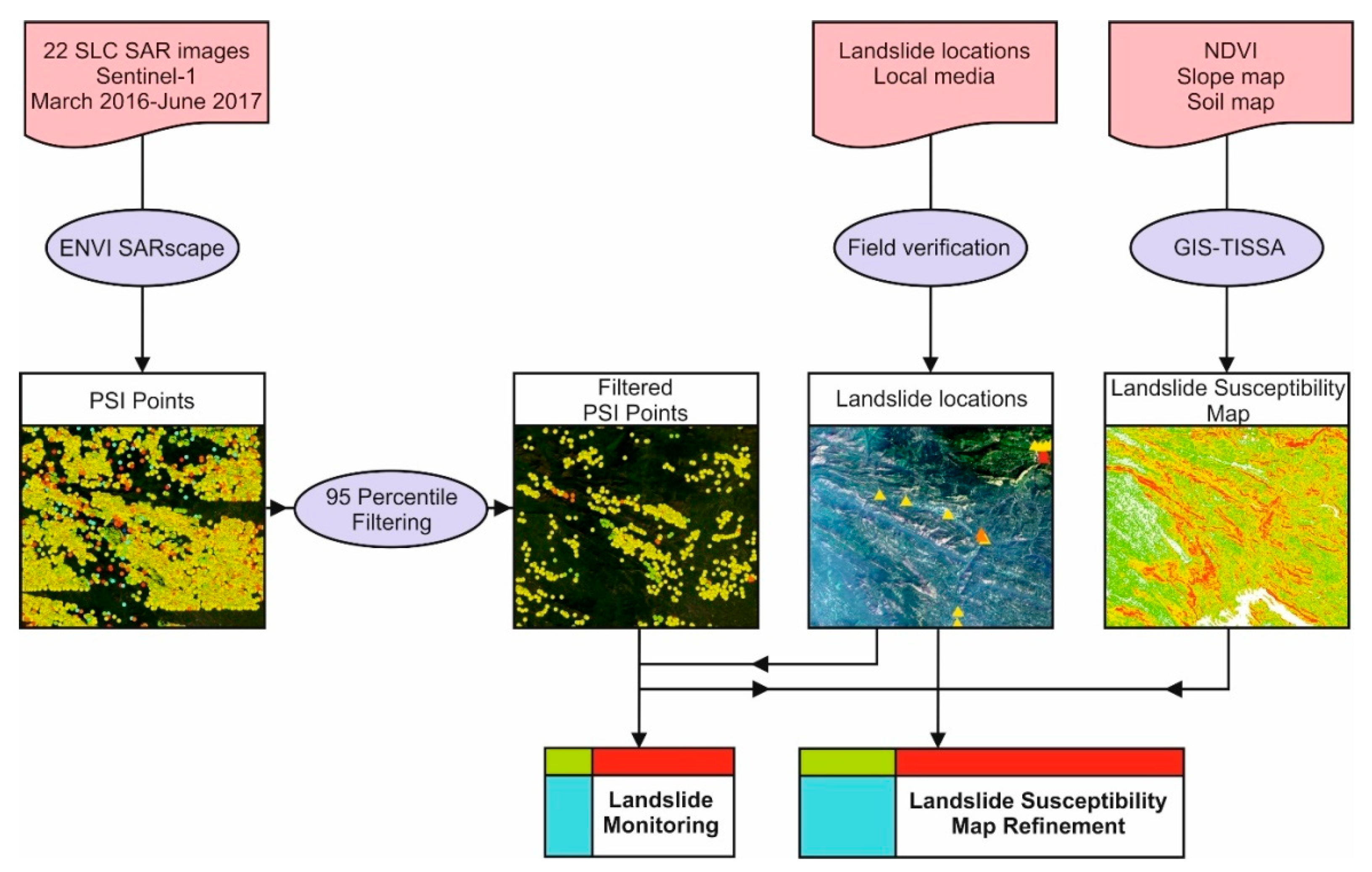
Twenty-two descending single look complex (SLC) synthetic aperture radar (SAR) images acquired between March 2016 and June 2017 from the Sentinel-1A satellite (Table 2), courtesy of the European Space Agency (ESA), were downloaded from the Alaska Satellite Facility at the University of Alaska Fairbanks [33]. Sentinel-1A acquires SAR images at an approximate wavelength of 5.6 cm (C-band) over an area with dimensions 250 by 180 km at a revisiting cycle of 12 days. The incidence angle for the Interferometric Wide Swath (IWS) mode ranges from 29.1 degrees to 46 degrees, with a central incidence angle of approximately 37.55 degrees. Sentinel-1A images were processed using the PSI technique to measure ground deformation rates with an accuracy up to 1 mm/yr [34] following the default approach provided with the ENVI SARscape software [19,20,35]. The methodology behind landslide mapping and monitoring is shown in Figure 2.

3.1. Selection of Landslide Location

Twelve different landslide locations were collated from various media sources, mostly newspaper articles, and verified through field studies. The details of these landslides are shown in Table 3. All these landslides were confined to roadcuts. These landslides were categorized into three groups based on activity periods that align with PSI data acquisition: Landslides that occurred before March 2016, i.e., representing landslide that occurred before the SAR data collection, are referred to as ‘Group 1’; between March 2016 and June 2017, i.e., landslides that occurred during the SAR data collection time-period, are referred to as ‘Group 2’, and after June 2017, i.e., landslides after the SAR data collection time-period, are referred to as ‘Group 3’ (Figure 3). Individual landslides were studied against the PSI deformation values. The dates of data were selected prior to the 2018 anomalous rainfall that occurred in Kerala which resulted in one of the biggest floods and 4726 landslides, so that more significant movements associated with this anomalous rainfall should not manifest in our results, thereby, any anomaly can be avoided.

3.2. Monitoring of Individual Landslides

These three categories of landslides were correlated with the temporal deformation of PSI points. These three groups were further subdivided into two based on the east-facing and west-facing slope. This classification is performed to account for the Line of Sight (LoS) of Sentinel-1A satellite that plays a vital role in the deformation direction measured using PSI. These Sentinel-1A images were acquired in descending mode. Thus, landslides can show up in PSI data in two ways:
  • Negative velocity values on west-facing slopes, indicating downward or westward (downslope) movement, and
  • Positive velocity values on east-facing slopes, indicating downward or eastward (downslope) movement.
This method will show good results for landslides with E–W oriented slopes (±45°) [36]. The east and west-facing slopes were determined using the 30 m spatial resolution Shuttle Radar Topographic Mission (SRTM) digital elevation model (DEM) downloaded from the United States Geological Survey (USGS) website [37].

3.3. Filtering of PSI Points

The PSI technique can produce a large number of points depending on the choice of a coherence threshold. Although all the points convey the same amount of information, they are affected differently by random noise and the strength of the signal being measured. To identify and isolate only the points that convey the maximum amount of information and avoid potential noise and artifacts (especially the influence of vegetation in the tropical region), we undertook a selection process looking for points with a high signal to noise ratio and signal quality utilizing the coherence value. For the filtering, we select only Persistent Scatterer (PS) points that have higher coherence than the 95-percentile.

3.4. Creation of Slope Stability Map

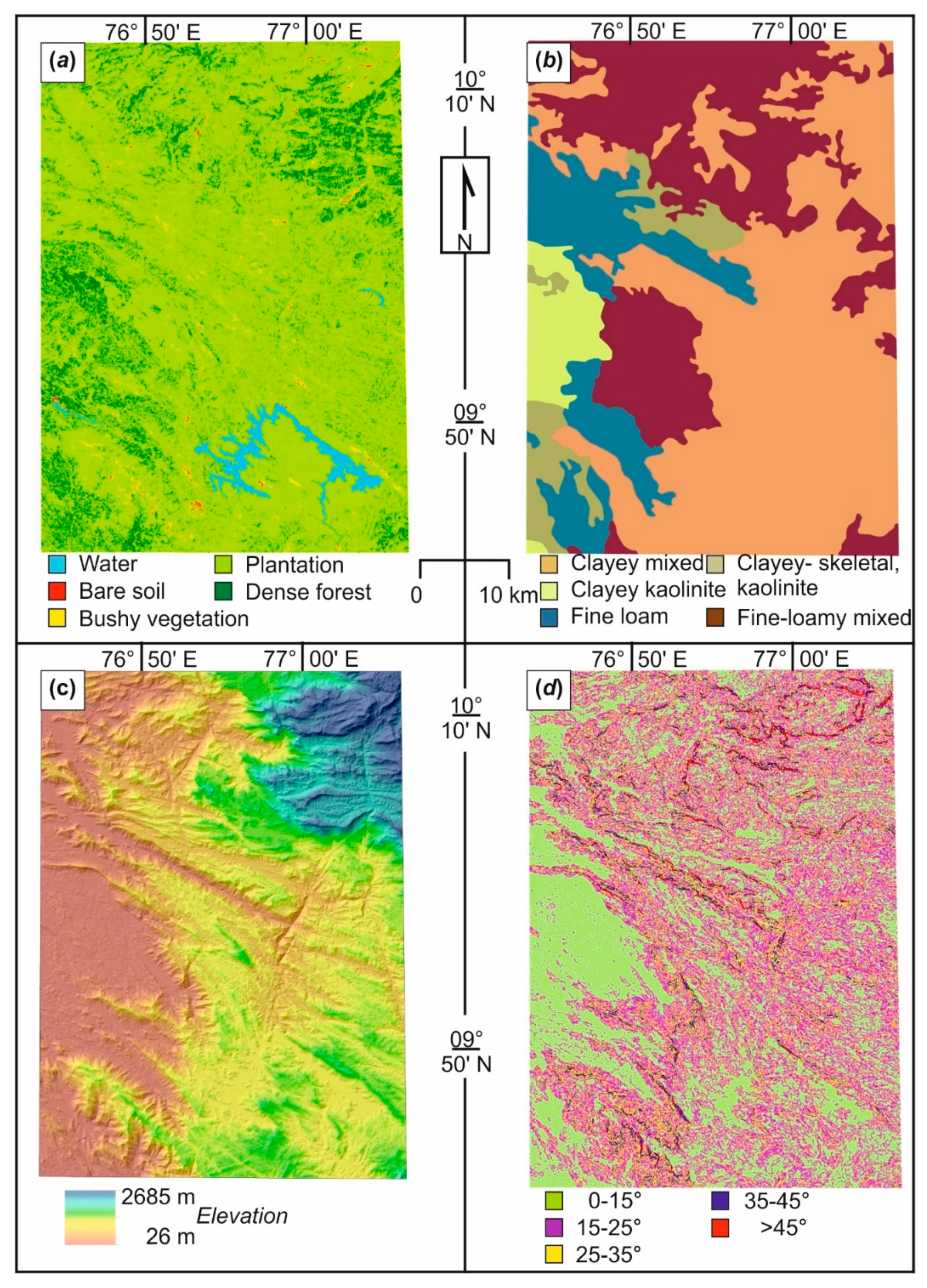
Geologic, hydrologic, and geomorphologic data, including the normalized difference vegetation index (NDVI), slope angle, groundwater level, and soil strength parameters, were used to create a landslide susceptibility map. NDVI was generated using the Near-Infrared (NIR) and Red bands of Landsat 8 [36]. The formula for NDVI generation is:
NDVI = ( NIR Red ) ( NIR + Red )
and was reclassified based on Holben [38]. The soil map was taken from the National Bureau of Soil Survey data [39], which used the Unified Soil Classification System (USCS). The slope map was prepared using SRTM data [40]. The slope map was classified based on the Bureau of Indian Standard [41]. All thematic maps used for the creation of landslide susceptibility map are shown in Figure 4. The spatial extent of the landslide susceptibility map was then reduced by a factor of safety (FS) analysis to identify and target landslide-prone slopes. An FS map was prepared based on input factors used in the Geographic Information System Tool for Infinite Slope Stability Analysis (GIS-TISSA) [42] and Probabilistic Infinite Slope Analysis model (PISA-m) [43]. The equation for calculating the FS is:
FS   =   c r + c s + [ q t + γ m D + ( γ sat γ w γ m ) H w D ] cos 2 β tan ϕ [ q t + γ m D + ( γ sat γ m ) H w D ] sin β cos β
where cr is root cohesive strength (pressure); cs is soil cohesive strength (pressure); qt is tree surcharge (pressure); γm is saturated unit weight of the soil (force/volume); γsat is moist unit weight of the soil (force/volume); D is soil thickness; Hw is pore pressure coefficient (0 ≤ Hw ≤ 1); β is the angle of topographical slope; φ is the angle of internal friction; In this study, we assumed a partially saturated soil condition (Hw = 0.5) for the slope stability analysis.

3.5. Refinement of Slope Stability Map

A slope aspect map of the study area was prepared, which was further edited as an east and west aspect map, by taking all pixels with values 0–180 as east and 180–360 as west. PSI points with positive values were extracted from eastern slopes, and PSI points with negative values were extracted from west-facing slopes. All PSI points belonging to a slope of 5 degrees or less were avoided as this area was deemed flat. A refinement matrix was created to refine the conventional FS map prepared using GIS-TISSA by taking into consideration the PS LoS velocities (VLoS).
Overlaying of these two derivatives, i.e., one prepared using GIS-TISSA and other using VLoS resulted in the combinations of different slope conditions. This final landslide-prone zone map includes three hazard classifications: unstable, critical, and stable.

4. Results

4.1. Monitoring Shallow Debris Flows

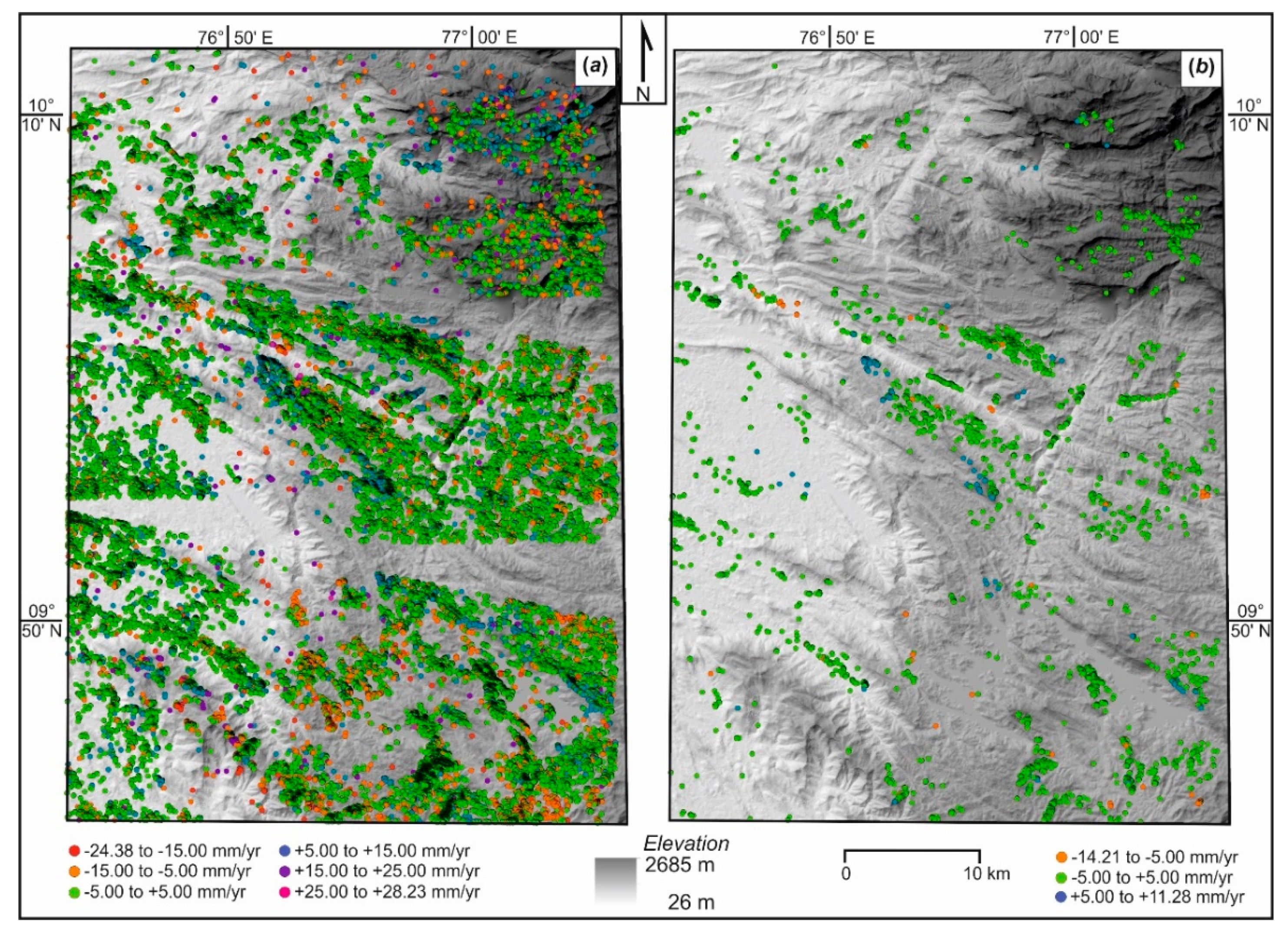
PSI results using the Sentinel-1A SLC SAR image are shown in Figure 5a. The small triangular cut-over portion is due to that fact that one Sentinel-1 image is composed of 27 smaller bursts. When such data is used for delineating the area of interest (AOI), AOI may overlap with multiple bursts. Thus, it is a pre-processing artifact. Figure 5a shows the VLoS (both positive and negative values). The PSI analysis provided 153,876 PS points, and each point yields average velocity values (mm/yr), incremental displacement values (mm) and total displacement values (mm). The velocity varies between −24.38 mm/yr to +28.22 mm/yr. 95-percentile coherence PS points were only selected for further analysis to avoid noise. The resulting PSI points were 9206 (Figure 5b). And these are the PSI points that were used in this study. The velocity of these points varies between −13.56 mm/yr to +11.28 mm/yr. The 12 landslide locations, collected from different sources and field verification (shown in Figure 1) were placed into three temporal groups: eight landslides in “Group 1”, two landslides in “Group 2”, and two landslides in “Group 3” and further classified into east and west-facing (Table 3).
PSI monitoring of landslides was done for these 12 landslides. Sentinel-1A on its descending mode characterizes the west-facing slope with negative velocity values, indicating down-slope or lateral movement to the west, and positive velocity values on east-facing slopes, indicating down-slope or lateral movement to the east [44,45,46]. Buffering was carried out as the landslides were demarcated based on local reports and hence may not represent landslide initiation points. Buffering was performed based on the run-out length of landslides, which is 101 m. The east-facing landslide having west-face slope in the buffer was removed and vice-versa, for getting more accurate results.
Out of the three different temporal periods, the Group 2 category shows the maximum deformation value (St Mary’s Orthodox Church with −35.67 mm) followed by Group 3 (Kamakshi village landslide with a deformation value of −28.03 mm) and Group 1 categories (NH-49 Salaf masjid landslide with −21.07 mm deformation). These three typical cases are shown in Figure 6. The rest of the temporal deformation graphs for other landslides are shown in Supplementary Material. All these landslides are west-facing. The maximum deformation recorded for the east-facing landslides is +10.11 mm/yr for Munnar–Gudaral Road landslide that belongs to Group 2. This was followed by +8.66 mm deformation for the Adimali–Rajakkad Road landslide that belongs to Group 3 category landslide. Group 1 has a maximum deformation of +8.53 mm, both for Painavu–Kattapana landslide and Thadiyampadu landslide. These deformations indicate that the maximum deformation is for the landslides that occurred during the time of PSI monitoring (Group-2), whereas the landslides that are going to happen in the future have smaller deformation compared to Group-2. It is also noted that sites that have experienced landslides in the past (Group-1) are also showing signs of deformation, which is indicative of reactivation and/or consolidation/settlement of landslides.

4.2. Mapping and Refining the Conventional FS Map

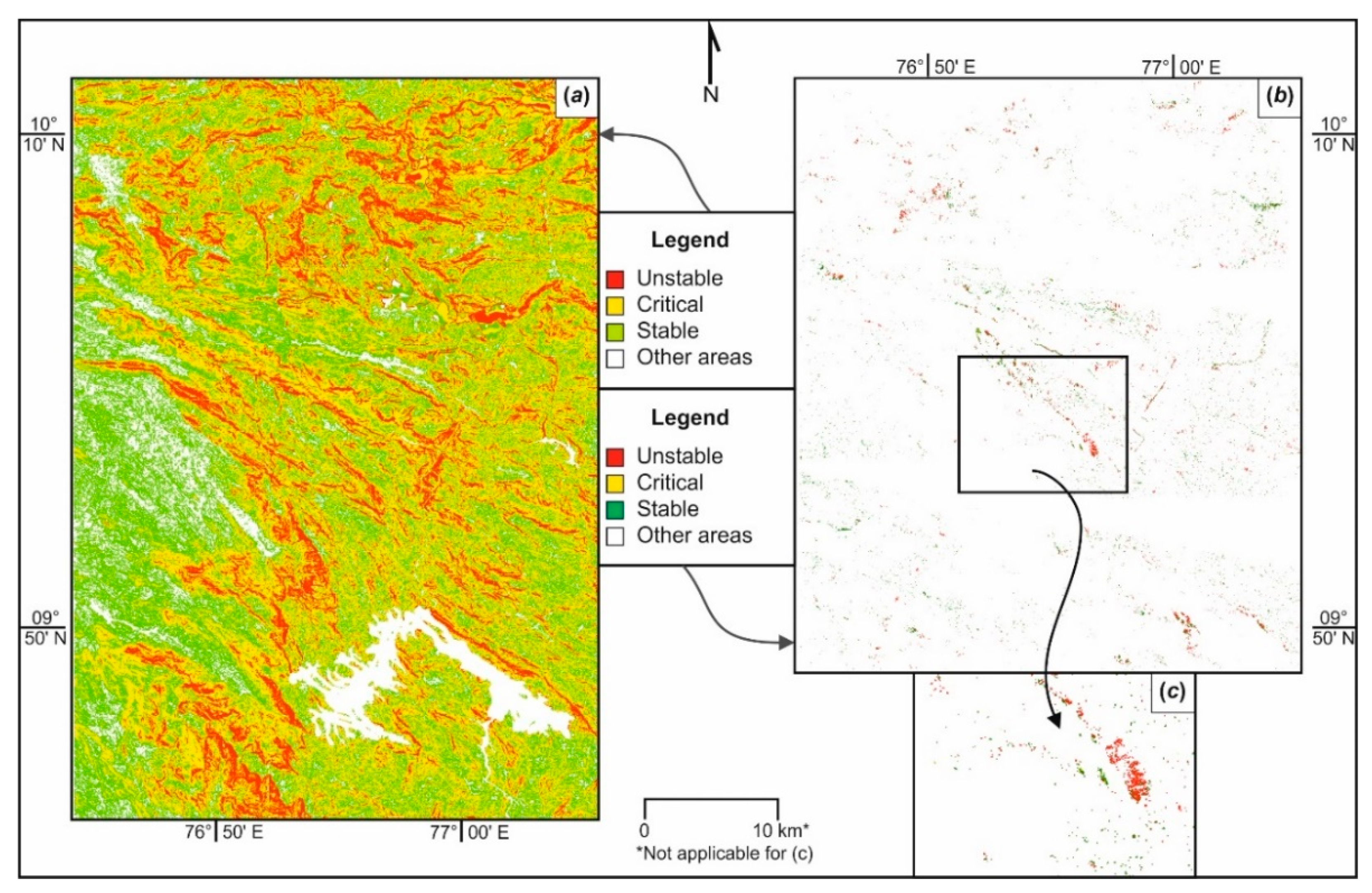
The conventional FS map prepared using GIS-TISSA (Figure 7a) was refined using PSI velocity values (Figure 7b,c). Since PSI measures the slant range displacement and velocities of ground points, landslide movements appear differently in the eastern and western slopes over any satellite orbital geometry (ascending or descending). Since all the images downloaded were of the descending mode, the landslides are observed as negative velocity points in the western slope and positive velocity points in the eastern slope. Thus, the PS points were divided on the basis of slope aspect as east and west. All points falling in the flat aspect were avoided as this area is physiographically plain and free from landslides. The rest of the points, after the 95-percentile filtering, were extracted. Upon extracting, the positive PS points in the eastern slope comprise 3852 points, and the negative PS points in the western slope amounted to 5023. It is to be noted that these numbers were generated after reducing the points on flat ground. The PS points in the east slope range from 0 to +11.28 mm/yr, whereas in the west slope, it spans from 0 to −23.03 mm/yr. This was divided into the equal class interval. The values between 0 and ±8 mm/yr are considered as low VLOS; velocity values between ±8 and ±16 mm/yr as medium VLOS and the rest as high VLOS. Thus, the eastern slopes do not have a high VLOS class. These points were used to refine the corresponding GIS-TISSA pixels in the eastern and western slopes using a conversion matrix (Figure 8a). Such a matrix was used by Ciampalini et al. [47]. Pixels in the unstable class were not changed. In the critical class, pixels coinciding with high-velocity PS points were moved to unstable class. Pixels coinciding with medium velocity were unchanged, while those that coincided with low velocity were moved to stable class. In the stable class, pixels coinciding with high-velocity PS points were moved to the critical class. At the same time, those coinciding with medium and low velocity was retained in the same class. After refining, it was found that there was a marked decrease in the percentage of pixels in the critical class (Figure 8b). Most pixels in the critical classes were deemed as stable, thereby reducing the number of false positives.

5. Discussion

The purpose of this study is to show the efficiency of PSI in monitoring and mapping shallow-seated landslides in tropical areas. Deformation caused by landslides, both local and regional scale, as well as both slow- or extremely slow-moving and fast-moving landslides can be studied by radar and can be evaluated using PSI [48]. In this study, 12 landslides, separated into three temporal categories based on PSI monitoring as Group 1, Group 2, and Group 3, which were further divided into east and west-facing landslides, were studied in detail to understand how PSI data can be utilized for studying shallow-seated landslides. The analyzed PSI data spanned from March 2016 through July 2017.
Landslides of these three periods also show characteristic deformation rates. This is because the monitoring period covers all the sequence of development of shallow-seated landslide viz. the monsoon season, the subsequent increase in pore-water pressure, and the final failure. The west-facing slopes showed the largest deformation values (e.g., St. Mary’s Orthodox Church landslide with a value of −35.67 mm), whereas the maximum for the east-facing landslides is +10.11 mm/yr for the Munnar–Gudaral Road landslide. Both belong to the Group 2 landslides. The second largest deformation values demonstrated category is Group 3 landslides. These deformations indicate that the maximum deformation is for the landslides that occurred during the time of PSI monitoring (Group 2), whereas the landslides that are going to happen in the future (Group 3) have smaller deformation compared to Group 2. It is also noted that sites that have experienced landslides in the past (Group 1) are also showing signs of deformation, which is indicative of reactivation and/or settlement/compaction of landslides. The West-facing Kamakshi village landslide with −28.03 mm and the east-facing Adimali–Rajakad Road landslide with +8.66 mm deformation belongs to Group 3. Lastly, in the category of Group 1 landslides, none of the developmental stages of the shallow-seated landslide were under surveillance, and hence the group was characterized by the least deformation value. NH-49 Salaf Masjid landslide with −21.07 mm deformation and +8.53 mm for Painavu landslide are in the Group 1 landslides. Bianchini et al. [48] and Cigna et al. [49] also used PSI data for describing the state of activity of landslides in Calabria Region, Italy. Similarly, Mateos et al. [50] used PSI as a measure to assess the damage caused by landslides in Granada, Spain.
An attempt to improve the existing landslide susceptibility map using PSI data was also attempted in this study. Accuracy of conventional landslide susceptibility maps needs improvement as it tends to have a large area of false positives and negatives. The method deployed to improve the accuracy, i.e., melding of GIS-TISSA derived landslide susceptibility map and PSI data, resulted in the refinement of the landslide susceptibility map. The ultimate result ended with a reduction in the critical category from 17 to 2 percentage points. This will help in efficient planning of disaster risk reduction activities.
Combining the PSI information with the slope stability model has significant practical implications. Traditionally, slope stability analysis is performed using physics-based [7] or statistical models [51]. Moreover, the models developed using these approaches are highly conservative, leading to several false positives. Because of the large false positives, the community often loses its confidence in these models and get desensitized to any early warning or risk predictions based on these models. Therefore, any opportunity to refine the slope stability model will enhance community confidence in risk estimations based on these models. The proposed approach that we have demonstrated in this study, combining PSI and the slope stability modeling, is a valuable step to achieve that goal. The combination of PSI with the stability model helped to refine the stability model output. The refined output (by eliminating false positives) also has significant economic implications as well. If the agency decides to monitor or mitigate the landslide risk at the critical location, then a refined output based on PSI and stability model would require fewer locations monitored or stabilized, which will provide cost savings.

6. Conclusions

This study is an attempt to monitor and map shallow-landslides set in a tropical set-up. The study resulted in the following conclusions:
  • The three types of temporal landslides pertaining to different periods of PSI analysis resulted in providing three distinct PSI velocity values. These refer to landslides that occurred before the analyzed time period, during PSI analysis, and after the analysis.
  • Traditional slope stability analysis methods often lead to significant false positives. The proposed approach combining PSI with traditional slope stability shows promise in reducing these false positives. The PSI derived velocity was used to refine the existing landslide susceptibility map. Such refinement will help to identify areas that require utmost priority in terms of monitoring or mitigation.
  • Developing countries like India will only have limited financial provisions for adopting management practices. The freely available radar data and the provisions of identifying areas requiring urgent management are able to be deciphered through studies like the one mentioned here.
  • Such an approach could also help the engineering community gain better community confidence as the slope stability model is more targeted and less susceptible to false positives.

Supplementary Materials

The following is available online at https://www.mdpi.com/2673-7418/1/1/2/s1. Supplementary material is PSI deformation plots for different landslide locations.

Author Contributions

Conceptualization, A.R. and K.S.S.; methodology, N.L. and C.L.V.; formal analysis, A.R., N.L. and C.L.V.; investigation, T.O. and V.M.; resources, E.H.B.; writing—original draft preparation, A.R., N.L. and C.L.V.; writing—review and editing, K.S.S. and T.O.; visualization, E.H.B. and V.M.; supervision, K.S.S. All authors have read and agreed to the published version of the manuscript.

Funding

No funding.

Institutional Review Board Statement

Not applicable.

Informed Consent Statement

Not applicable.

Data Availability Statement

Data will be shared based on request.

Acknowledgments

The authors thank the handling editor and anonymous reviewers for providing constructive remarks.

Conflicts of Interest

The authors declare no conflict of interest.

References

  1. Piciullo, L.; Calvello, M.; Cepeda, J.M. Territorial early warning systems for rainfall-induced landslides. Earth Sci. Rev. 2018, 179, 228–247. [Google Scholar] [CrossRef]
  2. Wieczorek, G.F. Landslides: Investigation and mitigation. In Landslides: Investigation and Mitigation, Special Report 247, Transportation Research Board, National Research Council; Turner, A.K., Schuster, R.L., Eds.; National Academy Press: Washington, DC, USA, 1996; pp. 76–90. [Google Scholar]
  3. Zamenian, H.; Koo, D.D. Tunnel asset management (TAM) program application for high risk structural components. J. Eng. Archit. 2014, 2, 1–12. [Google Scholar] [CrossRef] [Green Version]
  4. Martinović, K.; Gavin, K.; Reale, C.; Mangan, C. Rainfall thresholds as a landslide indicator for engineered slopes on the Irish Rail network. Geomorphology 2018, 306, 40–50. [Google Scholar] [CrossRef] [Green Version]
  5. Naidu, S.; Sajinkumar, K.S.; Oommen, T.; Anuja, V.J.; Samuel, R.A.; Muraleedharan, C. Early warning system for shallow landslides using rainfall threshold and slope stability analysis. Geosci. Front. 2018, 9, 1871–1882. [Google Scholar] [CrossRef]
  6. Rossi, M.; Kirschbaum, D.; Valigi, D.; Mondini, A.C.; Guzzetti, F. Comparison of Satellite Rainfall Estimates and Rain Gauge Measurements in Italy, and Impact on Landslide Modeling. Climate 2017, 5, 90. [Google Scholar] [CrossRef] [Green Version]
  7. Smith, D.M.; Oommen, T.; Bowman, L.J.; Gierke, J.S.; Vitton, J. Hazard assessment of rainfall-induced landslides: A case study of San Vicente volcano in central El Salvador. Nat. Hazards 2015, 75, 2291–2310. [Google Scholar] [CrossRef]
  8. Cruden, D.M.; Varnes, D.L. Landslide types and processes. In Landslides: Investigation and Mitigation, Special Report 247, Transportation Research Board, National Research Council; Turner, A.K., Schuster, R.L., Eds.; National Academy Press: Washington, DC, USA, 1996; pp. 36–75. [Google Scholar]
  9. Keaton, J.R.; De Graff, J.V. Surface observation and geologic mapping. In Landslides: Investigation and Mitigation, Special Report 247, Transportation Research Board, National Research Council; Turner, A.K., Schuster, R.L., Eds.; National Academy Press: Washington, DC, USA, 1996; pp. 178–230. [Google Scholar]
  10. Varnes, D.J. Slope movement types and processes. In Landslides: Analysis and Control, Special Report 176, Transportation Research Board, National Research Council; Schuster, R.L., Krizek, R.J., Eds.; National Academy Press: Washington, DC, USA, 1978; pp. 11–33. [Google Scholar]
  11. Thampi, P.K.; Mathai, J.; Sankar, G.; Sidharthan, S. Debris flow in Western Ghats-A regional evaluation. In Final Proceedings Tenth Kerala Science Congress; Kerala State Council for Science, Technology and Environment: Kozhikode, India, 1998; pp. 73–75. [Google Scholar]
  12. Sajinkumar, K.S.; Anbazhagan, S.; Rani, V.R.; Muraleedharan, C. A paradigm quantitative approach for a regional risk assessment and management in a few landslide prone hamlets along the windward slope of Western Ghats, India. Int. J. Disast. Risk Reduct. 2014, 7, 142–153. [Google Scholar] [CrossRef]
  13. Blaschke, T.; Lang, S.; Lorup, E.; Strobl, J.; Zeil, P. Object-oriented image processing in an integrated GIS/remote sensing environment and perspectives for environmental applications. Environ. Inf. Plan. Politics Public 2000, 2, 555–570. [Google Scholar]
  14. He, K.S.; Rocchini, D.; Neteler, M.; Nagendra, H. Benefits of hyperspectral remote sensing for tracking plant invasions. Divers. Distrib. 2011, 17, 381–392. [Google Scholar] [CrossRef]
  15. Li, X.; Yeh, A.G.O. Analyzing spatial restructuring of land use patterns in a fast growing region using remote sensing and GIS. Landscape Urban Plan. 2004, 69, 335–354. [Google Scholar] [CrossRef]
  16. Metternicht, G.; Hurni, L.; Gogu, R. Remote sensing of landslides: An analysis of the potential contribution to geo-spatial systems for hazard assessment in mountainous environments. Remote Sens. Environ. 2005, 98, 284–303. [Google Scholar] [CrossRef]
  17. Escobar-Wolf, R.; Oommen, T.; Brooks, C.N.; Dobson, R.J.; Ahlborn, T.M. Unmanned aerial vehicle (UAV)-based assessment of concrete bridge deck delamination using thermal and visible camera sensors: A preliminary analysis. Res. Nondestruct. Eval. 2018, 29, 183–198. [Google Scholar] [CrossRef]
  18. Devanthéry, N.; Crosetto, M.; Monserrat, O.; Cuevas-González, M.; Crippa, B. An Approach to Persistent Scatterer Interferometry. Remote Sens. 2014, 6, 6662–6679. [Google Scholar] [CrossRef] [Green Version]
  19. Ferretti, A.; Prati, C.; Rocca, F. Nonlinear subsidence rate estimation using permanent scatterers in differential SAR interferometry. IEEE Trans. Geosci. Remote Sens. 2000, 38, 2202–2212. [Google Scholar] [CrossRef] [Green Version]
  20. Ferretti, A.; Prati, C.; Rocca, F. Permanent scatterers in SAR interferometry. IEEE Trans. Geosci. Remote Sens. 2001, 39, 8–20. [Google Scholar] [CrossRef]
  21. Bouali, E.H.; Oommen, T.; Escobar-Wolf, R. Mapping of slow landslides on the Palos Verdes Peninsula using the California landslide inventory and persistent scatterer interferometry. Landslides 2018, 15, 439–452. [Google Scholar] [CrossRef]
  22. Casagli, N.; Frodella, W.; Morelli, S.; Tofani, V.; Ciampalini, A.; Intrieri, E.; Raspini, F.; Rossi, G.; Tanteri, L.; Lu, P. Spaceborne, UAV and ground-based remote sensing techniques for landslide mapping, monitoring and early warning. Geoenviron. Disasters 2017, 4, 1–23. [Google Scholar] [CrossRef]
  23. Cascini, L.; Peduto, D.; Pisciotta, G.; Arena, L.; Ferlisi, S.; Fornaro, G. The combination of DInSAR and facility damage data for the updating of slow-moving landslide inventory maps at medium scale. Nat. Hazards Earth Syst. Sci. 2013, 13, 1527–1549. [Google Scholar] [CrossRef]
  24. Gullà, G.; Peduto, L.; Antronico, L.; Fornaro, G. Geometric and kinematic characterization of landslides affecting urban areas: The Lungro case study (Calabria, Southern Italy). Landslides 2017, 14, 171–188. [Google Scholar] [CrossRef]
  25. Lu, P.; Catani, F.; Tofani, V.; Casagli, N. Quantitative hazard and risk assessment for slow-moving landslides from persistent scatterer interferometry. Landslides 2014, 11, 685–696. [Google Scholar] [CrossRef]
  26. Novellino, A.; Cigna, F.; Sowter, A.; Ramondini, M.; Calcaterra, D. Exploitation of the intermittent SBAS (ISBAS) algorithm with COSMO-SkyMed data for landslide mapping in north-western Sicily, Italy. Geomorphology 2017, 280, 153–166. [Google Scholar] [CrossRef]
  27. Schaefer, L.N.; Lu, Z.; Oommen, T. Dramatic volcanic instability revealed by InSAR. Geology 2015, 43, 743–746. [Google Scholar] [CrossRef] [Green Version]
  28. Schaefer, L.N.; Wang, T.; Escobar-Wolf, R.; Oommen, T.; Lu, Z.; Kim, J.; Lundgren, P.R.; Waite, G.P. Three-dimensional displacements of a large volcano flank movement during the May 2010 eruptions at Pacaya Volcano, Guatemala. Geophys. Res. Lett. 2017, 44, 135–142. [Google Scholar] [CrossRef] [Green Version]
  29. Sajinkumar, K.S. Geoinformatics in landslide risk assessment and management in parts of Western Ghats, Central Kerala, South India. Ph.D. Thesis, IIT Bombay, Mumbai, India, 2005, unpublished. [Google Scholar]
  30. Sajinkumar, K.S.; Oommen, T. Landslide Atlas of Kerala; Geological Society of India: Bangalore, India, 2020; p. 49. [Google Scholar]
  31. GSI. Geology and Mineral Resources of Kerala; Geological Survey of India: Thiruvananthapuram, India, 2005; p. 93. [Google Scholar]
  32. Nandakumaran, P.; Balakrishnan, K. Comparison of hydrochemical characteristics of shallow and depp aquifers in a hard rock terrain in Kerala, India. In Proceedings of the International Conference & Exhibition on Integrated Water, Waste Water and Isotope Hydrology, Bangalore, India, 25–27 July 2013. [Google Scholar]
  33. ASF: Alaska Satellite Facility Vertex: ASF’s Data Portal V3.04-54. Available online: https://vertex.daac.asf.alaska.edu/ (accessed on 8 September 2019).
  34. Crosetto, M.; Monserrat, O.; Cuevas-González, M.; Devanthéry, N.; Crippa, B. Persistent scatterer interferometry: A review. ISPRS J. Photogramm. Remote Sens. 2016, 115, 78–89. [Google Scholar] [CrossRef] [Green Version]
  35. Hooper, A.; Zebker, H.; Segall, P.; Kampes, B. A new method for measuring deformation on volcanoes and other natural terrains using InSAR persistent scatterers. Geophys. Res. Lett. 2004, 31, L23611. [Google Scholar] [CrossRef]
  36. Notti, D.; Herrera, G.; Bianchini, S.; Meisina, C.; Carlos, J.; Zicca, F. A methodology for improving landslide PSI data analysis. Int. J. Remote Sens. 2014, 35, 2186–2214. [Google Scholar] [CrossRef]
  37. USGS United States Geological Survey Earth Explorer. Available online: https://earthexplorer.usgs.gov/ (accessed on 8 September 2019).
  38. Holben, B.N. Characteristics of maximum-value composite images from temporal AVHRR data. Int. J. Remote Sens. 1986, 7, 1417–1434. [Google Scholar] [CrossRef]
  39. NBSS: National Bureau of Soil Survey. Soil Map of Kerala; National Bureau of Soil Science and Land Use Planning: Nagpur, India, 1996. [Google Scholar]
  40. JPL: Jet Propulsion Laboratory. Shuttle Radar Topography Mission, California Institute of Technology and the National Aeronautics and Space Administration. Available online: https://www2.jpl.nasa.gov/srtm/ (accessed on 3 July 2014).
  41. BIS: Bureau of Indian Standard. Indian Standard-Preparation of Landslide Hazard Zonation Maps in Mountainous Terrains-Guidelines; IS 14496 (Part 2); BIS: New Delhi, India, 1998; p. 20.
  42. Escobar-Wolf, R.; Sanders, J.; Vishnu, C.L.; Oommen, T.; Sajinkumar, K.S.A. GIS Tool for Infinite Slope Stability Analysis (GIS-TISSA). Geosci. Front. 2020. [Google Scholar] [CrossRef]
  43. Haneberg, W.C. PISA-m Map-based Probabilistic Infinite Slope Analysis: Version 1.0.1 User Manual [Updated March 2007]; Haneberg Geoscience: Seattle, WA, USA, 2007; p. 20. [Google Scholar]
  44. Stramondo, S.; Moro, M.; Tolomei, C.; Cinti, F.R.; Doumaz, F. InSAR surface displacement field and fault modelling for the 2003 Bam earthquake (southeastern Iran). J. Geodyn. 2005, 40, 347–353. [Google Scholar] [CrossRef]
  45. Lambiel, C.; Delaloye, R.; Strozzi, T.; Lugon, R.; Raetzo, H. ERS InSAR for assessing rock glacier activity. In Proceedings of the Ninth International Conference on Permafrost, Fairbanks, Alaska, 29 June–3 July 2008; Volume 1, pp. 1019–1025. [Google Scholar]
  46. Hu, J.; Li, ZW.; Ding, X.L.; Zhu, J.J.; Zhang, L.; Sun, Q. 3D coseismic displacement of 2010 Darfield, New Zealand earthquake estimated from multi-aperture InSAR and D-InSAR measurements. J. Geod. 2012, 86, 1029–1041. [Google Scholar] [CrossRef]
  47. Ciampalini, A.; Raspini, F.; Lagomarsino, D.; Catani, F.; Casagli, N. Landslide susceptibility map refinement using PSInSAR data. Remote Sens. Environ. 2016, 184, 302–315. [Google Scholar] [CrossRef]
  48. Bianchini, S.; Cigna, F.; Righini, G.; Proietti, C.; Casagli, N. Landslide HotSpot Mapping by means of Persistent Scatterer Interferometry. Environ. Earth Sci. 2012, 67, 1155–1172. [Google Scholar] [CrossRef]
  49. Cigna, F.; Bianchini, S.; Casagli, N. How to assess landslide activity and intensity with Persistent Scatterer Interferometry (PSI): The PSI-based matrix approach. Landslides 2013, 10, 267–283. [Google Scholar] [CrossRef] [Green Version]
  50. Mateos, R.M.; Azañón, J.M.; Roldán, F.J.; Notti, D.; Pérez-Peña, V.; Galve, J.P.; Pérez-García, J.L.; Colomo, C.M.; Gómez-López, J.M.; Montserrat, O.; et al. The combined use of PSInSAR and UAV photogrammetry techniques for the analysis of the kinematics of a coastal landslide affecting an urban area (SE Spain). Landslides 2017, 14, 743–754. [Google Scholar] [CrossRef]
  51. Oommen, T.; Cobin, P.F.; Gierke, J.S.; Sajinkumar, K.S. Significance of variable selection and scaling issues for probabilistic modeling of rainfall-induced landslide susceptibility. Spat. Inf. Res. 2018, 26, 21–31. [Google Scholar] [CrossRef]
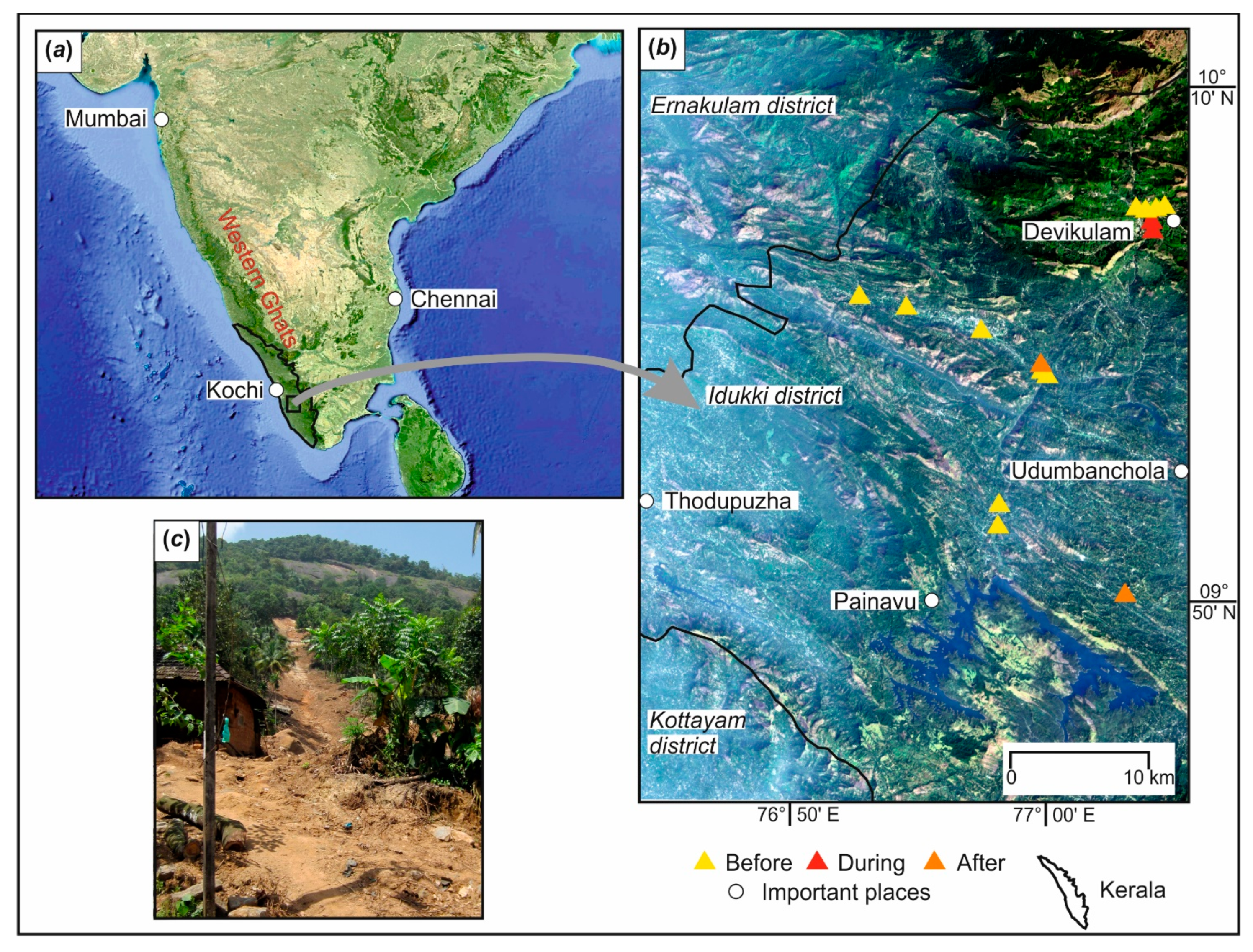
Figure 1. Location map of the study area: (a) with respect to South India (b) study area showing the location of landslides used in the present study (c) Field reconnaissance photo showing the ‘holotype’ shallow landslide occurring in the study area (Background image for (a,b): ArcGIS Earth).
Geomatics 01 00002 g001
Figure 2. Flow chart describing the methodology adopted in the study area.
Geomatics 01 00002 g002
Figure 3. Categorization of landslides in the study area based on Persistent Scatterer Interferometry (PSI) monitoring.
Geomatics 01 00002 g003
Figure 4. Data used for deriving landslide susceptibility map (a) normalized difference vegetation index (NDVI) map; (b) Soil map; (c) Elevation map draped over hillshade; (d) slope map.
Geomatics 01 00002 g004
Figure 5. PSI results using the Sentinel-1A SLC SAR image (Background image is Shuttle Radar Topographic Mission (SRTM) elevation map draped over hillshade) (a) Both positive and negative VLoS values; (b) Persistent Scatter (PS) points that have greater than 95-percentile coherence.
Geomatics 01 00002 g005
Figure 6. Deformation values of three typical landslides from Group 1, Group 2 and Group 3.
Geomatics 01 00002 g006
Figure 7. (a) Landslide susceptibility map prepared using Geographic Information System Tool for Infinite Slope Stability Analysis (GIS TISSA) (b) Refined landslide susceptibility map (c) Zoomed part of the refined landslide susceptibility map.
Geomatics 01 00002 g007
Figure 8. (a) Conversion matrix used for refining the conventional susceptibility map (b) Pie chart showing the changes in the stability classes prior and after refinement.
Geomatics 01 00002 g008
Table 1. Stratigraphic column for the state of Kerala (Source: Nandakumar and Balakrishnan [32]).
AgeFormationLithology
RecentAlluviumSand, clay, riverine alluvium etc.
Sub-recentLateriteDerived from crystalline and sedimentary rocks
TertiaryWarkalli
Quilon
Vaikom
Alappuzha
Sandstone, clays with lignite
Limestone, marl and clay
Sandstone with pebbles, clay and lignite Carbonaceous Clay and fine sand
UndatedIntrusivesDolerite, Gabbro, Granites, Quartzo-feldspathic veins
ArchaeanWayanad Group
Charnockites
Khondalites
Granitic gneiss, Schists etc.
Charnockites and associated rocks
Khondalite suite of rocks and its associates
Table 2. Dates of image acquisition of single look complex (SLC) synthetic aperture radar (SAR) images.
S.NoDate of Image AcquisitionS.NoDate of Image Acquisition
14 March 20161205 December 2016
215 May 20161329 December 2016
308 June 20161410 January 2017
414 July 20161511 March 2017
519 August 20161623 March 2017
612 September 20161704 April 2017
724 September 20161816 April 2017
806 October 20161928 April 2017
930 October 20162010 May 2017
1011 November 20162122 May 2017
1123 November 20162203 June 2017
Table 3. Landslide inventory of the study area.
S.NoLandslide LocationDirectionLat
N
Long
E
Date of OccurrenceDimension (m)Average PSI Velocity (mm/yr)
LWD
Before Monitoring
1NH-49 Salaf masjidWest10.03076.87905 August 2013550.5−4.6721
2NH-49 Machiplavu villageWest10.02376.91005 August 201310300.3−2.0795
3Painavu–Kattapana roadEast09.89376.97205 August 20131280.5−0.94653
4Adimali–Kirittodu roadEast10.00776.95905 August 201310101−1.6030
5Thadiyam paduEast09.88276.97004 August 20131051−0.0448
6Munnar Tea CountyWest10.08877.06524 June20137.58.51−4.9353
7Munnar MG colonyWest10.08877.07024 June 201316152−0.0091
8Munnar new colonyWest10.08977.07524 June2013450.4−0.5933
During Monitoring
9St. Mary’s orthodox church East10.08377.07028 June 20169152−0.1944
10Munnar–Gudaral roadEast10.08577.07028 June 20166151.5−1.9065
After Monitoring
11Adimali–Rajakad roadEast09.98576.99819 September 20171582−1.3890
12Kamakshi villageWest09.83577.05309 August 201775304−6.0173
Publisher’s Note: MDPI stays neutral with regard to jurisdictional claims in published maps and institutional affiliations.