Article

Nano-Silica-Modified Hydrophobic PDMS Encapsulation on CNT Thermoelectric Fibers for Waterproof Thermoelectric Textiles

Department of Light Chemical Engineering, School of Textiles Science and Engineering, Jiangnan University, Wuxi 214122, China
*
Authors to whom correspondence should be addressed.
Textiles 2025, 5(4), 52; https://doi.org/10.3390/textiles5040052
Submission received: 2 August 2025 / Revised: 4 October 2025 / Accepted: 14 October 2025 / Published: 22 October 2025

Abstract

Flexible and wearable thermoelectric devices can convert body waste heat into electricity, showing a new direction to solve the long-lasting issue of energy supply on portable devices. However, thermoelectric fibers are prone to short circuits and failure due to sweat stains and washing practices. Therefore, it is quite necessary to solve this problem to realize the practical thermoelectric device. PDMS, with its excellent insulation and flexibility, can effectively address short-circuit issues by encapsulating the surface of thermoelectric fibers. In this work, hydrophilic nano-silica (H-SiO2)-modified PDMS that insulates materials was prepared and coated on the surfaces of polyethyleneimine (PEI)- and hydrochloric acid (HCl)-treated dual-surface-modified thermoelectric fibers. The encapsulated fibers were then woven into spacer fabric to prepare thermoelectric textiles (TETs). After 50 water washing cycles, the fibers retained 97% of their conductivity, and the textiles continued to function normally underwater, indicating that the thermoelectric fibers are effectively protected under PDMS encapsulation.

1. Introduction

In the era of rapid development of the Internet of Things (IoT) and smart wearable technology, research into self-powered wearable systems has become increasingly in-depth, with thermoelectric fibers beginning to gain attention. Thermoelectric fibers can extract energy from temperature differences between the environment and the human body, providing a continuous and reliable power source for electronic devices. Additionally, they possess characteristics such as flexibility, lightweight design, and weavability, making them a popular choice for self-powered wearable devices [1,2,3,4,5,6,7]. Researchers have developed a variety of thermoelectric fibers using different fabrication methods. Among them, the most common approach is to coat thermoelectric materials onto conductive fibers via spraying or immersion techniques. Another important strategy involves directly spinning thermoelectric materials into fibers through methods such as melt spinning, wet spinning, or gel spinning. However, most thermoelectric fibers reported to date primarily focus on enhancing thermoelectric efficiency, with limited consideration of waterproof protection for real-world applications. Moreover, thermoelectric fibers fabricated by coating methods often suffer from delamination of the thermoelectric material layer after repeated washing, which significantly compromises their performance and durability [8,9]. Therefore, encapsulation protection for thermoelectric fibers is highly necessary.
CNTFs are widely employed in the fabrication of thermoelectric fibers owing to their exceptional electrical conductivity, flexibility, lightweight nature, and scalability. For example, Yu et al. designed PEI and Au NPs dual-surface modified CNTFs using carbon nanotube fibers [10]. We fabricated thermoelectric fibers using CNTFs and encapsulated them with polydimethylsiloxane (PDMS). PDMS is a highly elastic, hydrophobic, and electrically insulating organosiloxane with excellent biocompatibility and chemical stability, making it an ideal encapsulation material for thermoelectric fibers. However, high-concentration PDMS cannot be directly applied, as it tends to form bead-like aggregates on the fiber surface. To overcome this issue, PDMS must be diluted prior to coating. Hexane, a volatile solvent capable of dissolving PDMS, gradually evaporates during the curing process, enabling uniform adhesion of the PDMS layer onto the fibers [11,12,13,14,15,16]. Olivia Ojuroye used PDMS to encapsulate electronic textiles, which remained functional after 10 to 15 washes. This demonstrates that PDMS is a suitable encapsulation material for washable electronic textiles, offering sufficient strength and durability [17]. Isopropyl alcohol helps improve the surface tension of the solution, making the coating more uniform and stable, so a small amount of isopropyl alcohol is added to the solution [18,19].
In this work, CNTFs were dual-surface-modified with PEI and HCl and subsequently encapsulated with PDMS diluted in hexane and isopropyl alcohol. The encapsulated fibers were then sewn onto spacer fabrics to fabricate thermoelectric textiles. Performance tests demonstrated that the tensile strength of the encapsulated fibers increased to 76.68 MPa, with an elongation at break of 6.33%, both showing improvement compared to the unencapsulated fibers. The power factor of the encapsulated thermoelectric fibers was 4.14 μW, representing only a 3.8% decrease relative to the pre-encapsulation value. The fibers maintained normal operation underwater, and after 50 washing cycles, their electrical conductivity remained above 97% of the original value, reaching 1670.57 S/cm. When integrated into fabrics, the fibers withstood repeated bending, twisting, and folding without performance degradation. Moreover, because the encapsulation is applied to individual fibers prior to weaving rather than to the entire textile, the resulting structure exhibits significantly improved breathability compared to conventional single-layer encapsulation systems. This encapsulation strategy provides a reliable technical pathway for the long-term stable operation of wearable thermoelectric devices.

2. Experimental Section

2.1. Experimental Materials

Carbon nanotube fibers (CNTF) were prepared in-house [10,20]. Polyethyleneimine (PEI) was supplied by Shanghai Aladdin Biochemical Technology Co., Ltd., Shanghai, China. Aerogel silica, n-hexane, and isopropanol were all supplied by Shanghai Husi Co., Ltd., Shanghai, China. Ethanol was provided by Sinopharm Group Research Institute, China National Pharmaceutical Group Co., Ltd., Beijing 100050, China. Polydimethylsiloxane (PDMS) was purchased from Dow Chemical Company, Midland, Michigan, USA. Hydrochloric acid was purchased from Beijing Inno Chemical Technology Co., Ltd., Beijing, China.

2.2. Preparation of Gas-Phase Hydrophobic Nano-Silica and Investigation of PDMS Concentration

The native surface of gas-phase nano-silica (H-SiO2) contains a large number of hydrophilic Si–OH groups, which must be converted into hydrophobic groups for improved compatibility. Hydrophobic modification of gas-phase nano-silica was carried out using hexamethyldisilazane (HMDS), which reduces the surface energy and enhances compatibility with organic solvents.
First, 0.5 g of gas-phase SiO2 was dispersed in 50 mL of anhydrous hexane and sonicated for 10 min in an ice bath. HMDS was then added at a mass ratio of SiO2:HMDS = 1:2, and the reaction was performed under a nitrogen atmosphere. The mixture was refluxed at 70 °C for 6–8 h with magnetic stirring. The product was centrifuged at 8000 rpm for 10 min and washed three times with n-hexane. Finally, the sample was vacuum-dried at 60 °C for 2 h to obtain hydrophobic SiO2 (HB-SiO2).
Principle: ≡Si-OH + (CH3)3Si-NH-Si(CH3)3 → ≡Si-O-Si(CH3)3 + NH3
Additionally, PDMS was dissolved in hexane at a ratio of 1:20, and the hydrophobic nano-silica was incorporated into the PDMS to prepare a coating. The coating was applied onto a glass slide to evaluate hydrophobic performance.

2.3. Encapsulation of Thermoelectric Fibers

First, carbon nanotube fibers (CNTFs) were uniformly wound around a rectangular acrylic column measuring 5 mm × 5 mm × 10 cm (length × width × height), ensuring that the fibers were tightly wound without overlap. The ends of the fibers were secured with double-sided tape. A small amount of silver paste was applied at the contact points between the CNTFs and the edges of the acrylic column to facilitate subsequent differentiation between P-type and N-type carbon nanotubes.
For N-type doping, a 10 wt% polyethyleneimine (PEI) solution in ethanol was prepared and uniformly sprayed onto one side of the CNTFs on the acrylic column using a spray gun at a rate of 50 μL/cm. Non-sprayed areas were protected with tape and paper during the process. After spraying, the fibers were placed in a temperature-controlled oven at 60 °C for 5 min to ensure complete penetration and adhesion of the PEI solution to the fiber surface. The resulting PEI-doped CNTFs were designated as PEI/CNTFs.
For P-type doping, a hydrochloric acid (HCl) solution with a concentration of approximately 1 M was uniformly coated onto the opposite side of the PEI-coated fibers. Care was taken to ensure that the HCl coating was uniform and contrasted with the PEI layer to enhance the P-type doping effect. The treated fibers were then dried in a temperature-controlled oven at 60 °C for 5 min. The resulting HCl-doped CNTFs were designated as HCl/CNTFs.
After removing the P–N/CNTFs from the acrylic column, fiber encapsulation was performed. First, the encapsulation solution was prepared by mixing hexane with isopropyl alcohol at a volume ratio of 20:1 (hexane: isopropyl alcohol) until homogeneous. PDMS was then added to the solution at concentrations of 1, 2, 3, 4, and 5 wt% to prepare a series of coating solutions. The treated CNTFs were immersed in each solution for 5 min and then slowly withdrawn at a speed of 1 cm/s to ensure uniform coating of the PDMS layer. The fibers were subsequently dried in a temperature-controlled oven at 100 °C for 1 h, after which their mechanical properties were characterized to determine the optimal PDMS concentration. As shown in Figure 1, the process is illustrated schematically.
Next, 5 wt% of hydrophobically modified nano-SiO2 was incorporated into the PDMS solution. The previously encapsulated fibers were immersed in this solution for 5 min and then slowly withdrawn at 1 cm/s to achieve a uniform coating. The fibers were finally dried in a temperature-controlled oven at 100 °C.

2.4. Preparation of Thermal Electrical Components

The CNTFs, which had undergone multiple coating and curing processes, were carefully sewn onto a pre-prepared spacer fabric measuring 60 mm × 50 mm × 5 mm (length × width × height). The height of the spacer fabric was designed to match that of the P–N doped CNTFs, allowing the fibers to be well embedded within the fabric while exposing the undoped regions to the heat source, thereby forming π-type structures according to the fiber orientation. During sewing, care was taken to ensure that the fibers were arranged neatly and stably to prevent loosening.

2.5. Characterization and Performance Testing

The coatings and fibers were characterized using various techniques. The contact angle of the coatings deposited on glass slides was measured with a contact angle tester. The mechanical properties of CNTFs and encapsulated CNTFs were tested using a universal tensile testing machine (WDW-1, Jinan Hengsi Shengda Instrument Co., Ltd., Jinan, China), with test samples of 5 cm in length and a tensile speed of 10 mm/min. A Raman spectrometer (inVia Reflex, Renishaw, Wotton-under-Edge, Gloucestershire, UK)) was used to obtain Raman spectroscopy data at a wavelength of 785 nm. The crystal structure characteristics of the samples were analyzed using an X-ray diffractometer (D2 PHASER, Bruker AXS GmbH, Karlsruhe, Germany). A fully automatic TGA instrument was used to perform thermal gravimetric analysis (TG) on CNTF before and after treatment within a temperature range of 0 to 800 °C (TGA2, Mettler Toledo GmbH, Greifensee, Switzerland). Spectral data for nano-SiO2 powder samples were collected using a Fourier transform infrared spectrometer (FTIR). The conductivity σ (S cm−1) of CNTF was calculated using the formula σ = L/(R·S), where L is the sample length (cm), S is the cross-sectional area (cm2), and R is the resistance value measured at room temperature using a Keithley 6510 digital multimeter. The average of five measurements was used as the basis for data analysis. The Seebeck coefficient S (μV/°C) was calculated using a homemade device according to the formula S = −ΔV/ΔT, where ΔV was monitored by the Keithley 6510 digital multimeter, and ΔT was monitored using an infrared thermal imaging camera (DL700, Dali Technology Co., Ltd., Hangzhou, China) under 10 different thermal gradients to minimize experimental errors. Additionally, the fiber was sewn onto fabric and subjected to a wash resistance test according to AATCC 135 standards, followed by voltage measurement under temperature differences.
The experiment also used a Keithley 6510 digital multimeter to monitor the open-circuit voltage of the TET and a thermocouple to record the temperature difference between the upper and lower ends of the TET. An electrochemical workstation (CS150H, Wuhan Corrtest Instruments Corp., Ltd., Wuhan, China) was used to measure the U-I curve of the TET, and the power was calculated using the formula P = UI.

3. Results and Discussion

3.1. Coating Hydrophobicity and Fiber Mechanical Properties

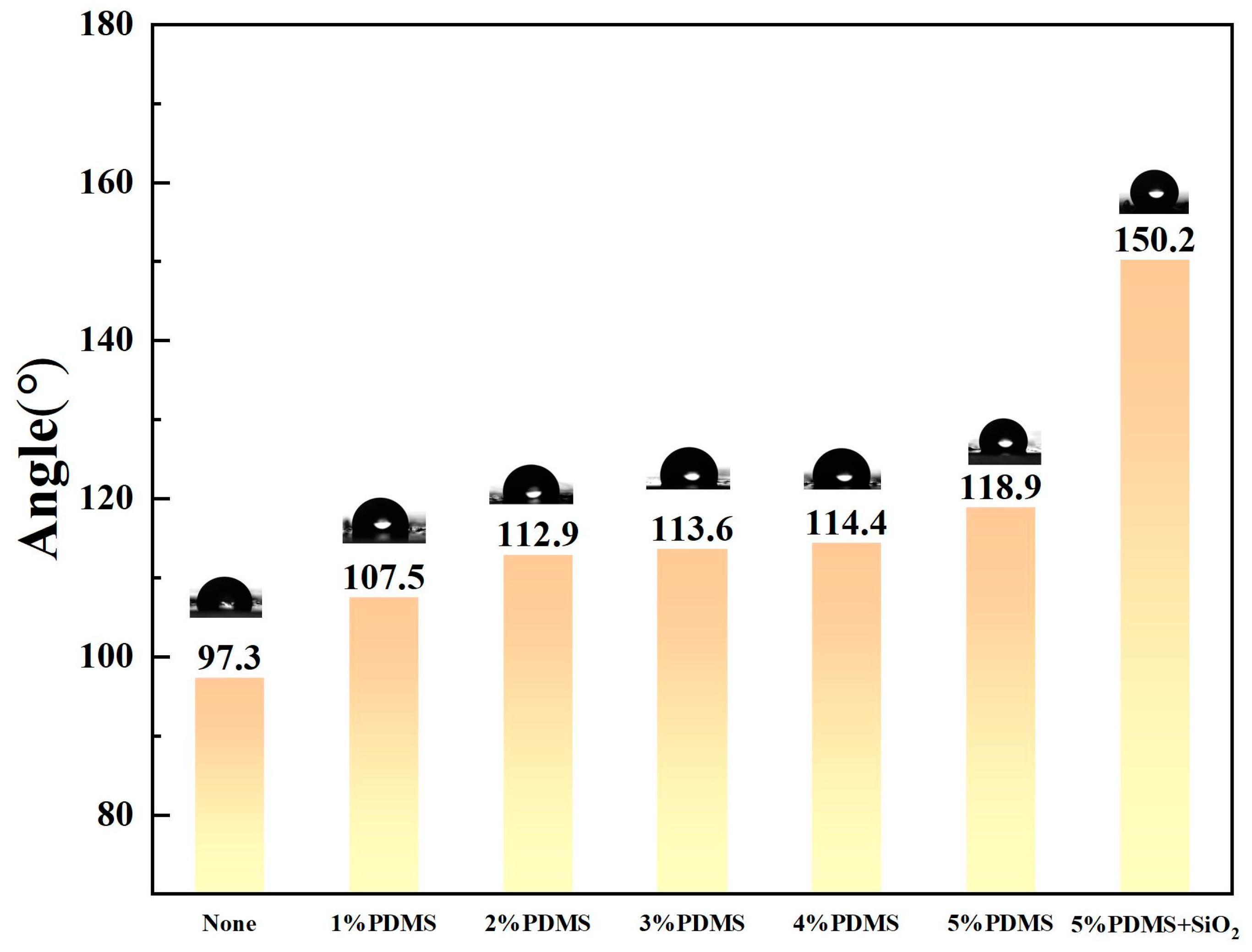
Figure 2 demonstrates that the PDMS coating markedly enhanced surface hydrophobicity, as evidenced by the substantial increase in the water contact angle from the initial state to 107.5–118.9°. Upon introducing hydrophobic nano-SiO2, the contact angle further increased to 150.2°, indicating a significant improvement in the coating’s hydrophobic performance.
Moreover, during the encapsulation of CNTF with PDMS at varying concentrations, high-concentration PDMS tended to aggregate and form droplets. To address this issue, hexane was used to dilute the PDMS, while isopropyl alcohol was added to increase the surface tension of the solution. The mechanical properties of the fibers before and after encapsulation served as the basis for optimizing the coating formulation. As shown in Figure 3, the mechanical performance was optimal at a PDMS concentration of 5%, with a fracture elongation of 6.33% and a tensile strength of 76.68 MPa. Therefore, in the experiment, a 5% PDMS solution was first applied and cured, followed by a second coating with 5% PDMS mixed with HB-SiO2.

3.2. Form and Structure

Morphological characterization and elemental distribution analysis of the samples were performed using scanning electron microscopy (SEM, including FESEM) and energy-dispersive spectroscopy (EDS). As illustrated in Figure 4a, untreated carbon nanotube fibers exhibited pronounced longitudinal grooves on their surfaces, whereas PEI doping adhered firmly to these regions. Figure 4b–i demonstrate that following treatment with PDMS or PDMS containing HB-SiO2, the surface grooves progressively diminished, resulting in smoother fiber surfaces. This confirms that PDMS effectively coated the fiber surface, filled structural defects, and consequently enhanced fracture strength. At higher magnification (Figure 4e,i), marked differences in surface morphology were observed between pure PDMS and HB-SiO2-containing PDMS coatings: the pure PDMS coating exhibited a relatively smooth surface (Figure 4e), whereas the HB-SiO2/PDMS coating displayed microscale protrusions (Figure 4i). Further magnification (Figure 4j–n) revealed that surface roughness varied with HB-SiO2 concentration. At 5 wt% HB-SiO2, the nanoparticles uniformly covered the fiber surface, forming micro-protrusions that generated a hierarchical roughness structure and enhanced the coating’s hydrophobicity. Post-encapsulation EDS mapping (Figure 4o,p) confirmed the uniform distribution of Si elements across the fiber surface. Quantitative elemental analysis indicated the composition of this region as C = 7%, O = 16%, and Si = 77%. Collectively, these SEM and EDS results verify effective PDMS adhesion and extensive incorporation of HB-SiO2 nanoparticles within the coating layer.
Additionally, Raman spectroscopy, XRD patterns, and Fourier transform infrared (FTIR) analysis were employed to further confirm that H-SiO2 was successfully modified into HB-SiO2 and that PDMS was effectively coated onto the CNTF surface (Figure 5a–c). FTIR analysis of SiO2 was first performed, with the upper curve representing treated SiO2 and the lower curve representing untreated SiO2 (Figure 5a). In the fingerprint region, the two spectra show similar profiles, exhibiting a strong absorption peak around 1100 cm−1, attributed to the asymmetric stretching vibration of Si–O–Si. A moderate peak at ~800 cm−1 corresponds to the symmetric stretching vibration of Si–O–Si, while a bending peak at ~460 cm−1 arises from the Si–O–Si bending vibration. However, in the functional group region, the untreated SiO2 shows a broad band at 3200–3500 cm−1 due to O–H stretching vibrations (from adsorbed water or Si–OH), which is absent in the treated sample. Instead, the treated SiO2 spectrum exhibits two weaker peaks at 2960 cm−1 and 2900 cm−1, corresponding to the asymmetric and symmetric stretching vibrations of –CH3 groups, respectively. These FTIR results confirm that hydroxyl groups on H-SiO2 were replaced by methyl groups, indicating the successful modification to HB-SiO2.
By comparing the Fourier transform infrared (FTIR) spectra of unmodified and modified nano-SiO2 (Figure 5a), we observed that in the fingerprint region (400–1500 cm−1), both the unmodified (lower curve) and modified (upper curve) nano-SiO2 exhibited similar characteristic peaks at 1100 cm−1 (Si–O–Si asymmetric stretching), 800 cm−1 (Si–O–Si symmetric stretching), and 460 cm−1 (Si–O–Si bending). In contrast, notable differences appeared in the functional group region (4000–1500 cm−1). Before modification, H-SiO2 showed a broad band at 3200–3500 cm−1, attributed to O–H stretching vibrations arising from surface hydroxyl groups or adsorbed water. After modification, this band disappeared, and new peaks at 2960 cm−1 and 2900 cm−1 emerged, corresponding to the asymmetric and symmetric stretching vibrations of –CH3 groups, respectively. These results indicate that hydroxyl groups were replaced by methyl groups during the hydrophobic modification process, confirming the successful transformation of H-SiO2 into HB-SiO2.
Figure 5b presents the Raman spectrum, where the first curve clearly exhibits the characteristic bands of carbon nanotubes: the D band at 1324 cm−1, the G band at 1573 cm−1, and the 2D band around 2700 cm−1. The D band corresponds to structural defects and disorder within the graphitic lattice, the G band arises from the in-plane vibration of sp2-bonded carbon atoms, and the 2D band is associated with the degree of graphitization and interlayer coupling [20]. In the third curve, distinct PDMS-related bands appear at 488 cm−1 and 2900–2960 cm−1, both at lower intensities than the characteristic peaks of the carbon nanotubes. The band at 488 cm−1 represents the symmetric bending vibration of the Si–O–Si bonds, while the peaks at 2900–2960 cm−1 are attributed to the rocking of methyl groups and C–H stretching vibrations, confirming the presence of Si–CH3 groups in PDMS. The second curve shows weak peaks in these two regions, further suggesting that PDMS is effectively adhered to the fiber surface. The fourth curve displays the XRD pattern of SiO2, in which no prominent diffraction peaks are observed.
Figure 5c presents the XRD patterns, where the third curve displays a weak peak around 2θ ≈ 12°. This feature arises because PDMS is a highly amorphous polymer lacking long-range ordered crystalline structures; therefore, its XRD pattern exhibits a broad hump rather than sharp diffraction peaks. The first curve corresponds to the XRD pattern of CNTF, showing a prominent (002) diffraction peak near 2θ ≈ 26° with high intensity and sharpness, indicating a high degree of graphitization and well-ordered crystalline structure of CNTs. A weaker peak at 2θ ≈ 43° corresponds to the (100) plane, reflecting the hexagonal lattice arrangement of carbon atoms within the graphite layers, while a very weak peak at 2θ ≈ 54° corresponds to the (004) plane. These peaks are observed in both CNTF and PDMS/CNTF; however, after PDMS coating, the (002), (100), and (004) peaks become significantly weakened, with the (004) peak nearly disappearing, while PDMS-related features remain evident at 2θ ≈ 12°. The fourth and fifth curves represent the XRD patterns of nano-SiO2 before and after modification, respectively, both showing no distinct diffraction peaks.

3.3. Thermocouple Performance

After measuring the resistance, length, and voltage generated at different temperatures for CNTFs doped with various thermoelectric materials, the conductivity and Seebeck coefficient of the fibers were calculated. As shown in Figure 6a,b, encapsulation has a minimal effect on the conductivity and Seebeck coefficient of the doped thermoelectric fibers. This is because, although carbon nanotube fibers inherently exhibit excellent conductivity, PDMS is applied only as a thin layer on the fiber surface, exerting negligible influence on the internal structure. Thermoelectric textiles (TETs) were fabricated by sewing P-type and N-type thermoelectric fibers into a spacer fabric in a Π-shaped configuration, as illustrated in Figure 5c, which effectively enhances device efficiency. The spacer fabric plays a critical role in improving TET performance by ensuring uniform heat distribution and reducing thermal conduction within the device. The thermoelectric textiles were subjected to water resistance testing according to the AATCC 135 standard. After 50 washing cycles, the conductivity remained stable, as shown in Figure 6d, with only slight decreases observed for fibers encapsulated with different dopants. The device demonstrated excellent flexibility under bending, twisting, and compression. To assess the actual performance of TET in water, the upper and lower surfaces of the thermoelectric device were tested under different temperatures, with output voltage and power measured at ΔT = 5 K to 25 K. The side in contact with air was the low-temperature end, while the side in contact with the heating platform was the high-temperature end. As the contact time increased, the temperature of the lower surface of the fabric gradually rose, with temperatures recorded using a thermocouple. The TET with 36 PN junctions achieved maximum output voltages of 26.5 mV and 132.3 mV at ΔT = 5 K and 25 K, respectively (Figure 6e), with corresponding maximum output powers of 0.17 μW and 4.14 μW (Figure 6e). The output voltage refers to the voltage measured at the output terminals of a thermoelectric device under different external load resistances. Its theoretical maximum value is the open-circuit voltage, which is the voltage measured when the output terminals are open-circuited (with infinite load resistance). The output power is the product of the output voltage and the output current, and its magnitude depends on the resistance value of the external load. When the output power reaches its maximum value, it is referred to as the maximum output power. We compared our device with others in terms of output voltage and output power (Figure 6f). Our thermoelectric device demonstrated outstanding performance, achieving a normalized open-circuit voltage of 5.29 mV·K−1 and a normalized power of 1.05 × 10⁻⁴ μW·K−2.

4. Conclusions

In summary, we prepared a PEI and HCl dual-surface-modified CNTF and encapsulated it with PDMS diluted with n-hexane and isopropanol. After encapsulation, we performed secondary encapsulation with HB-SiO2/PDMS to enhance the self-cleaning properties of the fibers. The encapsulated fibers were sewn onto spacer fabric to prepare thermoelectric textiles, and the mechanical and thermoelectric properties of the fibers and thermoelectric textiles before and after encapsulation were compared. The results showed that the tensile strength of the fibers increased to 76.68 MPa after encapsulation, with an elongation at a break value of 6.33%, representing an improvement over the pre-encapsulation values. The power factor of the encapsulated thermoelectric fiber was 4.14 μW, a decrease of only 3.8% compared to before encapsulation. The fiber could operate normally underwater, and after 50 washing cycles, the conductivity remained above 97% of the original value, reaching 1670.57 S/cm. When woven into fabric, it could withstand multiple bending, twisting, and folding operations. Since the encapsulation material is applied to the fiber before weaving rather than encapsulating the entire fiber, breathability is significantly superior to traditional single-layer encapsulation systems. This encapsulation scheme provides a reliable technical pathway for the long-term stable operation of wearable thermoelectric devices.

Author Contributions

Conceptualization, P.G. and D.L.; Methodology, B.Z., M.M., S.W. and H.C.; Validation, B.Z., D.L. and P.G.; Formal Analysis, B.Z.; Investigation, B.Z.; Resources, P.G. and D.L.; Data Curation, B.Z.; Writing—Original Draft Preparation, B.Z. and D.L.; Writing—Review and Editing, B.Z., D.L. and P.G.; Visualization, B.Z.; Supervision, D.L.; Project Administration, P.G. and D.L.; Funding Acquisition, P.G. and D.L. All authors have read and agreed to the published version of the manuscript.

Funding

Key Unveiling Project of Jiangxi Province: 20213AAE02017; Knowledge Transfer Project of Jiangsu Province: 202202641; Wuxi Health Commission Major Scientific Research Project: Z202418.

Institutional Review Board Statement

Not applicable.

Informed Consent Statement

Not applicable.

Data Availability Statement

The original contributions presented in the study are included in the article, further inquiries can be directed to the corresponding author.

Acknowledgments

This work was financially supported by the Key Unveiling Project of Jiangxi Province (20213AAE02017), the Knowledge Transfer Project of Jiangsu Province (no. 202202641), and the Wuxi Health Commission Major Scientific Research Project (Z202418).

Conflicts of Interest

The authors declare no conflicts of interest.

References

  1. Shen, Y.; Han, X.; Zhang, P.; Chen, X.; Yang, X.; Liu, D.; Yang, X.; Zheng, X.; Chen, H.; Zhang, K.; et al. Review on Fiber-Based Thermoelectrics: Materials, Devices, and Textiles. Adv. Fiber. Mater. 2023, 5, 1105–1140. [Google Scholar] [CrossRef]
  2. Liu, L.; Chen, J.; Liang, L.; Deng, L.; Chen, G. A PEDOT:PSS thermoelectric fiber generator. Nano Energy 2022, 102, 107678. [Google Scholar] [CrossRef]
  3. Kim, S.; Lim, S.; Jeong, M.H.; Kim, W.; Baik, S.; Suk, J.W. Flexible thermocouple using a thermoelectric graphene fiber with a seamless junction. J. Mater. Sci. Technol. 2024, 172, 15–22. [Google Scholar] [CrossRef]
  4. Xu, H.; Guo, Y.; Wu, B.; Hou, C.; Zhang, Q.; Li, Y.; Wang, H. Highly Integrable Thermoelectric Fiber. ACS Appl. Mater. Inter. 2020, 12, 33297–33304. [Google Scholar] [CrossRef]
  5. Yao, S.; Zhang, B.X.; Hu, S.; Zhu, H.X.; Hu, H.J.; Chen, K.L.; Li, D.W.; Gu, P. Phase-Separated Ductile Eutectogels with Excellent Environmental Durability and Antibacterial Features for Thermoelectric Response and Highly Sensitive Wearable Sensors. Chem. Mater. 2025, 37, 7064–7078. [Google Scholar] [CrossRef]
  6. Liu, Y.; Liu, P.; Jiang, Q.; Jiang, F.; Liu, J.; Liu, G.; Liu, C.; Du, Y.; Xu, J. Organic/inorganic hybrid for flexible thermoelectric fibers. Chem. Eng. J. 2021, 405, 126510. [Google Scholar] [CrossRef]
  7. Ding, T.; Chan, K.H.; Zhou, Y.; Wang, X.-Q.; Cheng, Y.; Li, T.; Ho, G.W. Scalable thermoelectric fibers for multifunctional textile-electronics. Nat. Commun. 2020, 11, 6006. [Google Scholar] [CrossRef] [PubMed]
  8. Qu, S.; Chen, Y.; Shi, W.; Wang, M.; Yao, Q.; Chen, L. Cotton-based wearable poly(3-hexylthiophene) electronic device for thermoelectric application with cross-plane temperature gradient. Thin Solid Film. 2018, 667, 59–63. [Google Scholar] [CrossRef]
  9. Lund, A.; Wu, Y.; Fenech-Salerno, B.; Torrisi, F.; Carmichael, T.B.; Müller, C. Conducting materials as building blocks for electronic textiles. MRS Bull. 2021, 46, 491–501. [Google Scholar] [CrossRef] [PubMed]
  10. Yu, L.; Liu, X.; Zhang, B.; Hu, H.; Chen, K.; Li, H.; Birch, D.; Chen, Y.; Qiu, H.; Gu, P. Phase-Transition-Promoted Thermoelectric Textiles Based on Twin Surface-Modified CNT Fibers. ACS Appl. Mater. Inter. 2024, 16, 18030–18039. [Google Scholar] [CrossRef]
  11. Qi, D.; Zhang, K.; Tian, G.; Jiang, B.; Huang, Y. Stretchable Electronics Based on PDMS Substrates. Adv. Mater. 2021, 33, 2003155. [Google Scholar] [CrossRef]
  12. Wolf, M.P.; Salieb-Beugelaar, G.B.; Hunziker, P. PDMS with designer functionalities—Properties, modifications strategies, and applications. Prog. Polym. Sci. 2018, 83, 97–134. [Google Scholar] [CrossRef]
  13. Shi, X.; Wei, H.; Zhou, W.; Soto Rodriguez, P.E.D.; Lin, C.; Wang, L.; Zhang, Z. Advanced strategies for marine antifouling based on nanomaterial-enhanced functional PDMS coatings. Nano Mater. Sci. 2024, 6, 375–395. [Google Scholar] [CrossRef]
  14. Wang, J.; Li, G.; Zhang, Z.; Huang, Q.; Niu, B.; Zhang, Y.; Long, D. Detailed insights of polydimethylsiloxane (PDMS) degradation mechanism via ReaxFF MD and experiments. Chem. Eng. J. 2024, 488, 150728. [Google Scholar] [CrossRef]
  15. Lee, H.J.; Kim, H.; Kim, T.S.; Kim, H.Y.; Mun, J.; Choi, G.; Jeong, H.E.; Yeo, J. Adhesive-free PDMS/PUA bilayer using selective photopolymerization for transparent, attachable, and wearable triboelectric nanogenerator. Nano Energy 2024, 121, 109274. [Google Scholar] [CrossRef]
  16. Bian, F.; Huang, R.; Li, X.; Hu, J.; Lin, S. Facile Construction of Chestnut-Like Structural Fireproof PDMS/Mxene@BN for Advanced Thermal Management and Electromagnetic Shielding Applications. Adv. Sci. 2024, 11, 2307482. [Google Scholar] [CrossRef] [PubMed]
  17. Ojuroye, O.; Torah, R.; Beeby, S. Modified PDMS packaging of sensory e-textile circuit microsystems for improved robustness with washing. Microsyst. Technol. 2022, 28, 1467–1484. [Google Scholar] [CrossRef]
  18. Viegas, I.M.A.; Rinnan, Å.; Andersen, S.I. Effect of Isopropanol on the Fluorescence of Crude Oil-in-Water Dispersions. Energy Fuels 2023, 37, 5757–5765. [Google Scholar] [CrossRef]
  19. Wei, L.; Yue, G.; Hongjian, P.; Hongying, C. Dispersion stability of titanium dioxide in aqueous isopropanol with polymer dispersant. J. Coat. Technol. Res. 2020, 17, 1083–1090. [Google Scholar] [CrossRef]
  20. Liu, X.; Yu, L.; Wang, S.; Cai, H.; Ran, X.; Xie, J.; Guo, Z.; Chen, K.; Li, H.; Gu, P. In-Situ Growth of Self-Reduction MXene/AuNP-Decorated CNT Yarns (CNTYs) for One-Dimensional Textile Heaters with Exceptional Electrothermal Performance. ACS Appl. Electron. Mater. 2025, 7, 303–312. [Google Scholar] [CrossRef]
  21. Hyland, M.; Hunter, H.; Liu, J.; Veety, E.; Vashaee, D. Wearable thermoelectric generators for human body heat harvesting. Appl. Energy 2016, 182, 518–524. [Google Scholar] [CrossRef]
  22. Jang, D.; Park, K.T.; Lee, S.-S.; Kim, H. Highly stretchable three-dimensional thermoelectric fabrics exploiting woven structure deformability and passivation-induced fiber elasticity. Nano Energy 2022, 97, 107143. [Google Scholar] [CrossRef]
  23. Park, K.T.; Lee, T.; Ko, Y.; Cho, Y.S.; Park, C.R.; Kim, H. High-Performance Thermoelectric Fabric Based on a Stitched Carbon Nanotube Fiber. ACS Appl. Mater. Inter. 2021, 13, 6257–6264. [Google Scholar] [CrossRef] [PubMed]
  24. Sun, T.; Zhou, B.; Zheng, Q.; Wang, L.; Jiang, W.; Snyder, G.J. Stretchable fabric generates electric power from woven thermoelectric fibers. Nat. Commun. 2020, 11, 572. [Google Scholar] [CrossRef] [PubMed]
  25. Elmoughni, H.M.; Menon, A.K.; Wolfe, R.M.W.; Yee, S.K. A Textile-Integrated Polymer Thermoelectric Generator for Body Heat Harvesting. Adv. Mater. Technol. 2019, 4, 1800708. [Google Scholar] [CrossRef]
  26. Lee, J.A.; Aliev, A.E.; Bykova, J.S.; de Andrade, M.J.; Kim, D.; Sim, H.J.; Lepró, X.; Zakhidov, A.A.; Lee, J.B.; Spinks, G.M.; et al. Woven-Yarn Thermoelectric Textiles. Adv. Mater. 2016, 28, 5038–5044. [Google Scholar] [CrossRef]
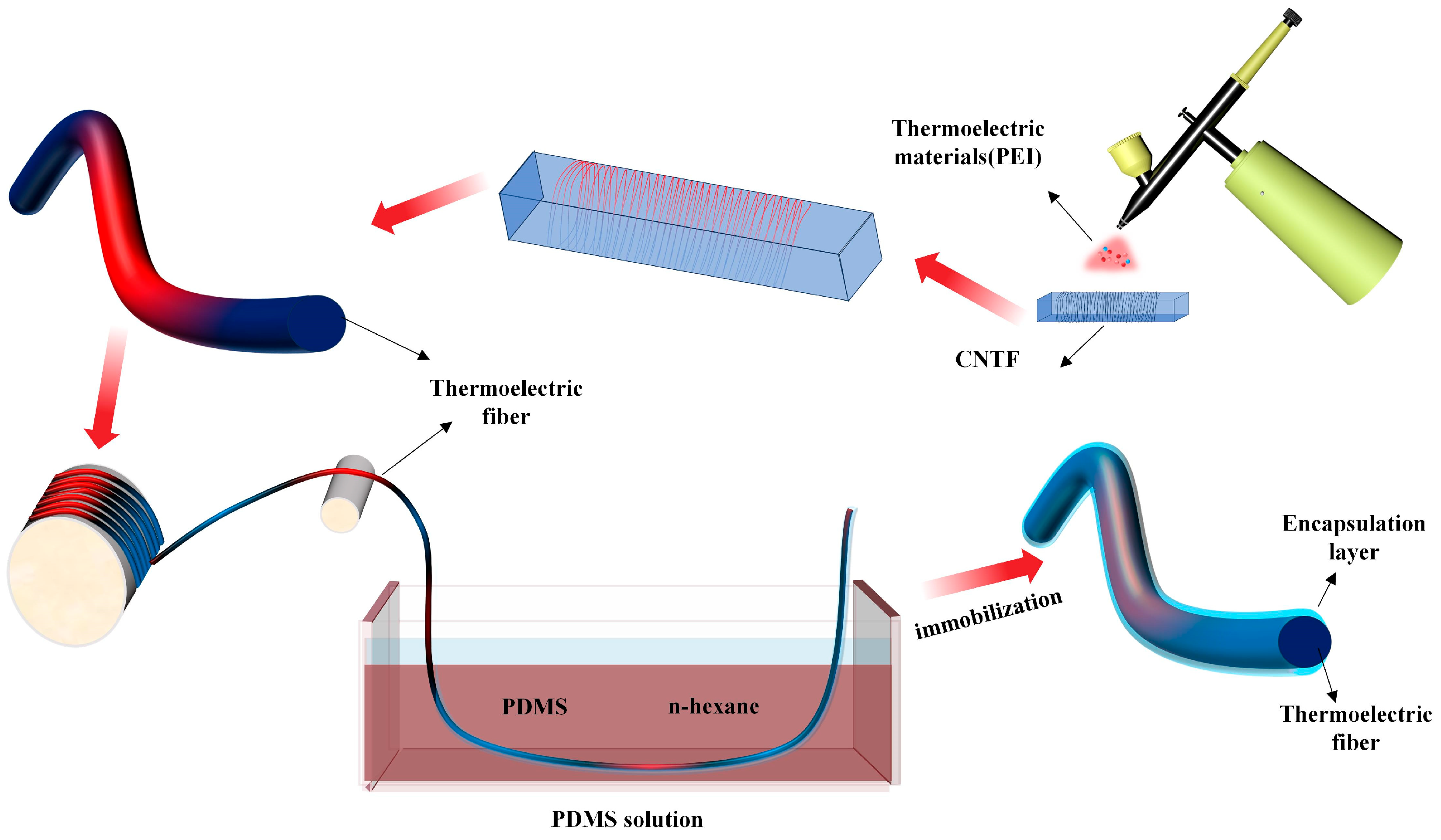
Figure 1. Schematic diagram of carbon nanotube fiber modification and encapsulation.
Textiles 05 00052 g001
Figure 2. Water contact angle of PDMS coatings of different concentrations and PDMS coatings modified with nano-SiO2.
Textiles 05 00052 g002
Figure 3. (a) Stress–strain curves of PDMS-encapsulated fibers with a large concentration gradient. (b) Stress–strain curves of PDMS-encapsulated fibers with a small concentration gradient.
Textiles 05 00052 g003
Figure 4. FESEM images of CNT fibers under different conditions: (a) pristine CNTs (scale bar: 100 μm); (be) after PDMS coating at various magnifications (scale bars: 100 μm, 30 μm, 15 μm, and 3 μm, respectively); (fj) after coating with PDMS containing 5 wt% HB-SiO2 at various magnifications (scale bars: 100 μm, 30 μm, 15 μm, 3 μm, and 1 μm, respectively); (kn) after coating with PDMS containing 4, 3, 2, and 1 wt% HB-SiO2, respectively (scale bar: 100 μm for all); (o) EDS image and (p) corresponding elemental composition of CNTF after secondary encapsulation with HB-SiO2-containing PDMS.
Textiles 05 00052 g004
Figure 5. (a) Fourier transform infrared spectra of hydrophilic SiO2 and hydrophobic SiO2. (b) Raman spectra of pristine carbon nanotube fibers, PDMS, PDMS-coated carbon nanotube fibers, and HB-SiO2. (c) XRD characterization of H-SiO2, HB-SiO2, pristine CNT, PDMS, and PDMS-coated carbon nanotube fibers.
Textiles 05 00052 g005
Figure 6. (a) Measurement of the conductivity of CNTF, HCl/CNTF, FeCl3/CNTF, PEI/CNTF, and OA/CNTF after encapsulation. (b) Measurement of the Seebeck coefficient of CNTF, HCl/CNTF, FeCl3/CNTF, PEI/CNTF, and OA/CNTF after encapsulation. (c) Schematic diagram of the thermoelectric device. (d) Conductivity and its change rate after washing cycles. (e) Relationship between TET output voltage and output power and temperature gradient. (f) Comparison Chart of Normalized Output Voltage and Output Power for This Fabric and Other Thermoelectric Fabrics [4,8,10,21,22,23,24,25,26].
Textiles 05 00052 g006
Disclaimer/Publisher’s Note: The statements, opinions and data contained in all publications are solely those of the individual author(s) and contributor(s) and not of MDPI and/or the editor(s). MDPI and/or the editor(s) disclaim responsibility for any injury to people or property resulting from any ideas, methods, instructions or products referred to in the content.