Abstract
Polyethylene terephthalate (PET) films were modified by direct fluorination using fluorine gas at room temperature and 660 torr for reaction times ranging from 10 min to 5 h. Some of the fluorinated samples were dried at 70 °C for 7 days. FT-IR and XPS analyses confirmed the successful incorporation of fluorine into the PET structure, with the formation of -CHF- and -CF2- groups. The degree of fluorination increased with the reaction time, but excessive reaction led to the formation and loss of CF4. Drying further decreased the fluorine content due to the continued CF4 formation. XRD revealed that fluorination increased the crystallinity of PET owing to increased polarity, whereas drying decreased the crystallinity owing to increased crosslinking. The DSC results showed an increase in the glass transition temperature (Tg) after fluorination and drying, which was attributed to increased polarity and crosslinking, respectively. The surface hydrophilicity of PET increased significantly with fluorination time, and the water contact angle decreased to as low as 3.35°. This was due to the introduction of polar fluorine atoms and the development of a rough and porous surface morphology, as observed by AFM. Interestingly, drying of the fluorinated samples led to an increase in the water contact angle, with a maximum of 85.95°, owing to increased crosslinking and particle formation on the surface. This study demonstrates a simple and effective method for controlling the hydrophilicity and hydrophobicity of PET surfaces via direct fluorination and drying.
1. Introduction
Polyester is an integral part of our daily lives. Among the types of polyester, polyethylene terephthalate (PET) is widely used in films, blow-molded bottles, containers, and packaging. Due to its advantages, PET firmly occupies the first place in the market [1,2,3]. Its preparation method is similar to that of other polyesters, which requires etherification/ester exchange, pre-condensation, and polycondensation [4]. In addition, PET is one of the most commonly used polymer materials in the healthcare field because of its biocompatibility, high uniformity, excellent mechanical strength, and corrosion resistance [5,6].
However, the low surface free energy of PET films remains a major impediment to their industrial use, leading to significantly poor adhesion and printability properties. Currently, a variety of surface modifications on PET have been studied, such as chemical etching [7,8], plasma immersion ion implantation [9,10], chemical vapor deposition [11,12], corona discharge [13,14], and ultraviolet (UV) light [15,16]. Compared with conventional chemical and physical methods, the fluorination of a polymer surface with fluorine gas is an effective chemical method for modifying and controlling the physicochemical properties of polymers. The introduction of low-polarity fluorine atoms can effectively change the hydrophilicity and hydrophobicity of PET surfaces. Luzinov et al. prepared a series of fluorine-containing oligomeric polyesters via polycondensation reactions and added them to PET films. As they easily migrate to the surface of the films, they significantly improve the waterproof and oil-repellent properties of the film edges [17]. Lee et al. used oxygen plasma to uniformly form nanostructures on the surface of the PET substrate and plasma–polymer–fluorocarbon was coated on the nanostructure surface by medium-frequency sputtering to obtain anti-reflective and superhydrophobic films. The results showed that the WCA of the composite films could be as high as 153°and the reflectivity could be as low as 4.2% [18]. Du et al. prepared novel nanostructures by depositing fluorocarbon polymer coatings on PET fibers by sputtering polytetrafluoroethylene. The newly constructed nanoscale network exhibited high hydrophobicity, with a WCA as high as 145° [19]. The direct use of fluorine-containing gases to introduce fluorine atoms into PET is also a research hotspot. Cheng et al. modified the PET surface using low-pressure CF4 plasma in a roll-to-roll, double-sided treatment system. The results showed that the surface properties of the two sides of the surface were different from each other. The WCA on one side was 7.56°, indicating hydrophilicity, whereas the WCA on the other side was 108.63°, indicating hydrophobicity [20]. Liu et al. prepared fluorinated PET at 30 °C for various durations using an F2/N2 mixture gas with a volume fraction of 12.5% F2. The study found that the surface chemistry and structure were significantly altered by the fluorination. The introduction of a large number of highly polar groups increased the surface hydrophilicity of fluorinated PET films compared to unmodified PET films, and this hydrophilicity increased significantly with longer fluorination time [21]. Kim et al. used F2 gas to modify the PET surface at 25 °C and different gas concentrations for 1 h to improve the adhesion between the polymer matrix and the metal plating films. The results showed that the adhesion strength of nickel increased owing to the increased roughness and hydrophilicity of the surface after fluorination [22]. However, the method of constructing the composite coating does not introduce fluorine atoms into the PET. After the fluorinated layer was peeled off, the hydrophobicity disappeared completely. This fails to fundamentally alter the properties of PET. In addition, the introduction of oligomeric segments and blending with PET require chemical synthesis, purification, and other steps that affect the performance of the product in subsequent applications. The operational steps are complex, and the yield remains uncertain. Fluorinated PET can be obtained by directly using fluorine gas, which is easy to operate, reacts rapidly, and has a high atom utilization rate. The surface states of the fluorinated layer can be controlled using both the fluorination conditions and the drying process. The polymer surface can be rendered hydrophobic or hydrophilic by a combination of fluorination and drying. This is the novelty and motivation of this study.
In this study, we attempted to modify the PET surface using F2 gas and explored the physical and chemical properties as well as the morphology of the surface at high concentrations of F2 gas and for different durations. In addition, this study dried some of the fluorinated samples to explore the effect of temperature on the fluorinated layers.
2. Materials and Methods
2.1. Surface Fluorination of PET
PET films (10 × 10 × 1.2 mm), obtained from TAKIRON Corporation (Tokyo, Japan), were washed with ethanol to remove organic residues from their surfaces. Fluorine gas (99.5%) was purchased from Daikin Industries, Ltd. (Osaka, Japan). The PET films were placed in a nickel reaction vessel (24 mm × 32 mm × 5 mm) and held at 25 °C under vacuum (0.1 Pa) for 24 h to eliminate impurities from the system. The fluorination apparatus was described in a previous paper by the current authors [23], which used a reaction temperature of 25 °C, a gas pressure of 660 torr, and reaction times of 10 min, 15 min, 30 min, 1 h, and 5 h. The samples were named FPET10min, FPET15min, FPET30min, FPET1h and FPET5h, respectively.
2.2. Drying of Fluorinated PET
After fluorination, the fluorinated samples were placed in a vacuum for 7 d at 70 °C. The dried samples were named PETdry, FPET10min-dry, FPET15min-dry, FPET30min-dry, FPET1h-dry and FPET5h-dry.
2.3. Material Characterization
The chemical compositions of all PET samples were determined using Fourier-transform infrared (FT-IR) absorption spectroscopy (Nicolet 6700; Thermo Electron Scientific, Waltham, MA, USA). The analysis was conducted in the transmittance mode at 500–4000 cm−1, from which 32 scans were acquired and air background removal was performed. The surface chemical states of all PET samples were determined using X-ray photoelectron spectroscopy (XPS; JPS-9010, JOEL, Tokyo, Japan). All binding energies were referenced to a carbon peak of 284.8 eV. The crystal structures of all PET samples were investigated using X-ray diffraction (X-ray diffraction; XRD-6100, SHIMADZU, Ltd., Kyoto, Japan). Differential scanning calorimetry (DSC) was conducted using a thermal analyzer (NETZSCH DSC 214 Polyma, Selb, Germany) to determine the glass transition temperature (Tg) of PET. The samples (15 mg) were initially heated from 30 to 200 °C at a heating rate of 2 °C·min−1 under an Ar atmosphere. TGA of the samples was performed using a TA Instruments (TG/DTA 7200, HITACHI, Tokyo, Japan). The samples (20 mg) were heated from 25 to 450 °C at a rate of 10 °C·min−1 under an Ar atmosphere. The surface topography was evaluated using atomic force microscopy (AFM; Nanoscope IIIa, Digital Instruments, Tokyo, Japan). Scanning was conducted in tapping mode within an area of 10 µm × 10 µm. The arithmetic mean surface roughness was determined from the AFM roughness profile. The water contact angle (WCA) of all PET samples was measured at 25 °C using the sessile drop method. A 10 µL water droplet was used in a telescopic goniometer with a magnification power of 23× and a protractor with a graduation of 1° (Krüss G10, Hamburg, Germany). Five measurements were acquired at different surface locations on each sample to determine the average value (±2°).
3. Results and Discussion
3.1. Effects of Fluorination and Drying on the Surface Composition and Structure
Figure 1 shows the FT-IR spectra of the (a) fluorinated and (b) dried samples. The stretching vibrations of -CH2- at 2928 cm−1 and -CH- at 2853 cm−1 in the spectra of the fluorinated and dried samples were both weakened. The -COX of the acid halide peak appeared at 1770 cm−1, which was -COF. The -C=C- bending vibration peak on the substituted benzene appears at 1620 cm−1, which is the substitution of fluorine on the benzene of -CHF-. The -CF2- stretching vibration peak appears at 1244 cm−1 [24,25]. This indicates that the PET was partially fluorinated. At short reaction times, the peak intensities of -CH2- and -CH- were significantly weakened, whereas those of -COF and -CF2- were significantly enhanced. In contrast, at a longer reaction time, the peak intensities of -CH2- and -CH- were slightly weakened, and -COF and -CF2- were enhanced. This is because the fluorine radicals do not overreact at low reaction times, resulting in the substitution of hydrogen atoms to form -CHF- and -CF2-. However, due to the excessive reaction of fluorine radicals during long fluorination times, the -CHF- and -CF2- groups were converted into CF4, which expresses the carbon atoms on the skeleton combining with fluorine and forming CF4 as well as overflowing from the sample surface. Therefore, a difference in the peak intensity was observed between the two reaction times.

Figure 1.
FT-IR spectra of (a) fluorinated and (b) dried samples.
For the dried samples (b), the peaks did not change significantly, indicating that heating did not change the groups after fluorination. However, the intensities of all peaks decreased. This may be because the reaction occurred after heating, and CF4 continued to be formed and overflowed from the surface, causing the peak intensity to decrease further.
As shown in Figure 2, the untreated PET sample shows a strong C-C peak at 284.8 eV, which decreases after fluorination and drying. The C-C bonds were converted into C=O (287.9 eV), -CHF- (289.5 eV), and -CF2- (291.5 eV) in the fluorinated samples [26]. During fluorination, the samples with shorter fluorination times exhibited stronger intensities of peaks for -CHF- and -CF2- than the samples with longer fluorination times. With an increase in the reaction time, the intensities of the peaks for -CHF- and -CF2- decreased continuously [20]. This result is consistent with that of FT-IR spectra. This further indicates that, in the early stage of the reaction, fluorine radicals replace hydrogen to form -CHF- and -CF2-groups. In the later stage (more than 1 h), excessive reaction caused CF4 gasification from the surface. The XPS spectrum shows that the peak intensities of -CHF- and -CF2- decrease with increasing fluorination time. As shown in Figure 3, the intensities of the F 1s peaks were similar to those of the C 1s peaks. Below 30 min of fluorination, the fluorination proceeded with increasing duration. However, at a 1 h fluorination time, the intensity of the F 1s peaks decreased drastically.
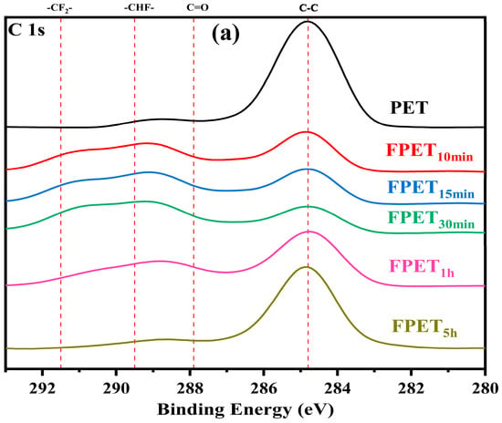

Figure 2.
XPS spectra (C 1s) of (a) fluorinated and (b) dried samples.


Figure 3.
XPS spectra (F 1s) of (a) fluorinated and (b) dried samples.
For all dried samples, the peak intensities of -CHF- and -CF2- decreased, and the -CF2- peak of samples with longer fluorination times disappeared, as shown in Figure 2. The fluorine content on the surface of the samples decreased after drying, as shown in Figure 3. These results were consistent with the FT-IR spectra after drying. Heating triggered a reaction and continued to form CF4, overflowing from the sample surface, thereby reducing the fluorine concentration of all the samples.
The XPS results (C 1s and F 1s) show that the fluorinated peaks can be maintained in samples with shorter fluorination times without CF4 gasification. The drying process can cause the fluorinated peaks to decrease because fluorination may proceed and reach CF4 gasification [27].
XRD analysis is useful for comparing the crystallinities of the samples. The XRD analysis of all samples revealed a prominent broad peak at 20.43°, which was assigned to PET [28]. As shown in Figure 4a, all fluorinated samples exhibited higher peaks than untreated PET. This is because fluorine atoms increase the polarity of PET and crystallinity of the film surface. However, when the samples were heated, the crystallization peaks of all the fluorinated samples decreased. In particular, the crystallization peaks of the dried samples with shorter fluorination times were lower than those of the samples with longer fluorination times. Heating the fluorinated samples may increase the crosslinking density of the surface owing to decreased crystallization. Because the fluoride layer formed on the fluorinated samples is also drastically affected by the fluorination time, the effects of heating on the crystallinity of the fluorinated samples depend on the fluorination conditions.
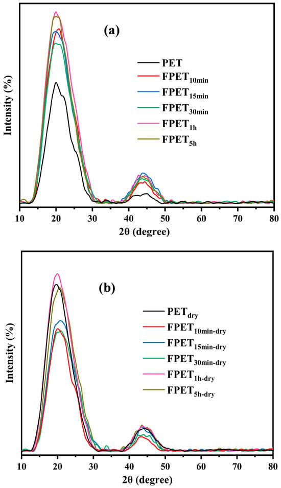
Figure 4.
XRD patterns of (a) fluorinated and (b) dried samples.
In summary, the characteristic peaks of fluoride in all fluorinated and dried samples were detected using FT-IR and XPS analyses. The reaction process is that fluorine radicals first replace hydrogen to form the polar group (-CHF- and -CF2-), and then, owing to excessive reaction, fluorine radicals continue to replace hydrogen to form CF4 gasification from the sample surface.
Therefore, the content of the polar groups (-CHF- and -CF2-) in the low-reaction-time samples was higher than that in the high-reaction-time samples. After drying, as the temperature increased, fluorination proceeded on the surface, and CF4 gasification occurred, which further reduced the fluorine content. XRD analysis revealed that the crystallinities of the samples exhibited opposite trends after fluorination and drying. The former is dominated by polarity, whereas the latter is controlled by the degree of surface crosslinking of the polymer.
3.2. Effects of Fluorination and Drying on Thermodynamic Properties
Figure 5 shows the DSC results for (a) fluorinated and (b) dried samples. Among the fluorination samples, the Tg values of both FPET10min and FPET15min were almost 68 °C, which was higher than those of the untreated and other fluorinated samples. This may be due to the formation of more fluoride (-CHF- and -CF2-) groups on the sample surface. This is because the fluoride layer on the surface can stably exist within 15 min of the fluorination. However, the Tg of the samples with longer fluorination times decreased and became similar to that of the untreated sample. A longer fluorination time caused the CF4 gasification of in the fluoride layer on the surface. In the case of the FPET30min samples, many fluoride bonds may have caused a stronger repulsive reaction between the fluoride bonds. This decreased the Tg compared with that of the FPET10min and FPET15min samples.

Figure 5.
DSC results of (a) fluorinated and (b) dried samples.
After drying, the Tg values of all fluorinated samples increased. In particular, the Tg of samples with shorter fluorination times could be increased to 72 °C, whereas the Tg of samples with longer fluorination times was 68 °C. When PET is heated, the molecular chains are close together. The fluorine atoms on the chain segments form hydrogen bonds with the hydrogen atoms of other chains. This increases the crosslinked density of PET, as well as the Tg. The amplitude of improvement increased with increasing fluorine content.
Figure 6 shows the TGA curves of the (a) fluorinated and (b) dried samples, respectively. The TGA curves of all the samples did not change after fluorination and drying. This indicates that the fluorination was performed only on the surface of the PET. Therefore, the internal structures of the fluorinated and dried samples may be similar to those of untreated PET. The thermal stability of the fluorinated and dried samples did not change significantly compared to that of the untreated sample.
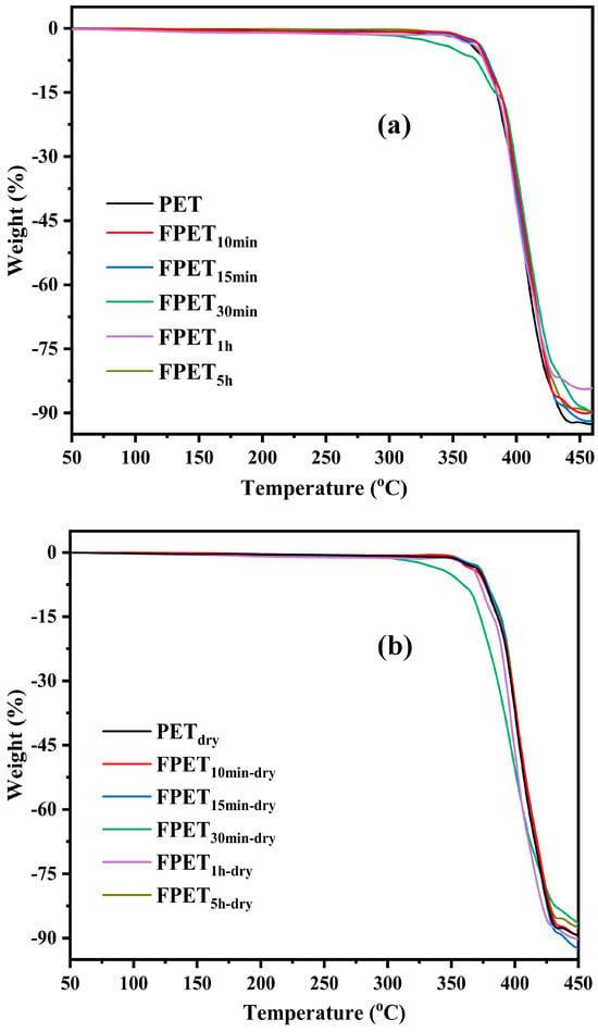
Figure 6.
TGA curves of (a) fluorinated and (b) dried samples.
3.3. Effects of Fluorination and Drying on the Surface Properties and Morphology
The water contact angle (WCA) can be measured to determine whether the film surface is hydrophilic or hydrophobic. Figure 7a shows the WCA of the untreated and fluorinated PET samples. For the untreated PET film, the WCA was 78.69°. However, after fluorination, the WCA of all the fluorinated samples decreased. In addition, the longer the reaction time, the lower was the WCA. In particular, the WCA of the FPET5h sample decreased drastically to 3.35°, and it exhibited superhydrophilicity. Figure 7b shows the WCA results for the dried samples after fluorination. Consequently, the WCA increased significantly after the samples were dried. Among them, FPET15min-dry reached 86° on a nearly hydrophobic surface. This may be attributed to the reduction of the hydrophilic fluoride layer after drying, as shown in the XPS results (Figure 2 and Figure 3).
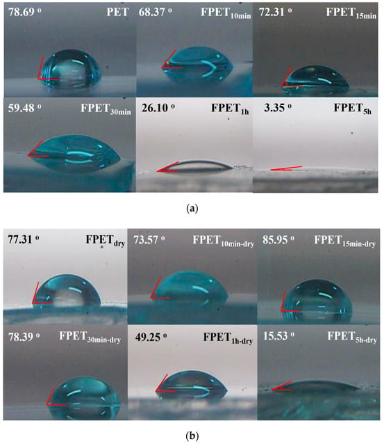
Figure 7.
(a) WCA results for untreated and fluorinated samples; (b) WCA results of the dried samples after fluorination.
When the fluorination reaction begins, the introduced fluorine atoms increase the surface polarity. This indicates a good affinity for water as a polar solvent. Simultaneously, as the reaction time increased, the degree of fluorination increased, and CF4 gasification from the sample surface was observed. This CF4 gasification causes a rough and porous surface that affects the degree of water infiltration. After drying, the surface chains of the samples were close to each other, and the reaction was initiated at elevated temperatures. The results showed that polar molecules increased the crosslinking density through hydrogen bonding between chains, thereby increasing the WCA. However, because PET contains hydrophilic ester groups, the crosslinked density is insufficient to convert the surface into hydrophobicity compared to ester groups. Therefore, the WCA was less than 90°.
AFM measurements were useful for observing the surface changes to confirm the effect of fluorination and drying on the surface roughness of the PET samples. Figure 8a,b show the AFM images of the fluorinated and dried samples, respectively. The FPET10min and FPET15min samples did not change significantly compared to the untreated samples. However, the surface roughness of the samples fluorinated for more than 30 min increased significantly. This may be due to the CF4 gasification on the surface during fluorination. In particular, the roughness (Ra) of FPET5h was 13.7 nm, which is four times higher than that of untreated PET. The increased surface roughness strongly affects the wettability of water, as shown in Figure 7a. Although the roughness of the samples fluorinated for more than 30 min of fluorination time was not significantly different, the WCA was significantly different. This may be due to the different surface states of the samples. After more than 30 min of fluorination, the -CHF- and -CF2- on the surface gradually changed into hydrophobic -CF3 bonds with CF4 gasification. In the case of fluorination times exceeding 1 h, almost all -CF3 bonds were converted into CF4 gasification, and new -CHF- and -CF2-bonds were formed on the surface in the reaction with F2 gas. After heating, the surface roughness (Ra) of all dried samples increased. In particular, the surface roughness (Ra) of the dried samples with fluorination times greater than 30 min increased significantly. This may be due to CF4 gasification from the fluoride layer formed on the surface. Because the drying process was carried out in vacuum, the surface after CF4 release cannot have any formation of new polar groups (-CHF- and -CF2-). This may have caused the WCA values to be higher than those of the fluorinated samples, as shown in Figure 7a. In addition, the increase in the density of crosslinks after drying will be another reason.
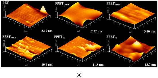

Figure 8.
(a) AFM images of untreated and fluorinated samples; (b) AFM images of the dried samples after fluorination.
As shown in Figure 9, the hydrophilicity of the PET surface gradually increased with an increase in the fluorination time, and the roughness also increased with the fluorination time. For the fluorinated samples (■), the water contact angle (WCA) decreased with increasing roughness of the PET surface, as shown in Figure 9. The relationship between the WCA and surface roughness was the same as that of the dried samples after fluorination. This may be explained by the wetting behavior of the liquid on the Wenzel model surfaces [29,30].
where θew is the apparent contact angle on the rough surface, and r is the roughness factor. On a Wenzel surface, the liquid fills the grooves on the hydrophilic surface with a contact angle of less than 90°, and the contact angle decreases with increasing roughness. Hence, it was concluded that the surface of the fluorinated PET followed the Wenzel model.
cosθew = r cosθe
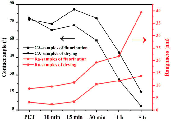
Figure 9.
Changes in the contact angle and roughness of different fluorination times and drying.
To obtain a more intuitive understanding of the fluorinated layer on the sample surface, thickness tests were performed simultaneously on the fluorinated and dried surfaces. The thickness of the fluorinated film was measured using a thin-film measurement system (F20-UV, Filmetrics, CA, USA), where the spectral range was 380–1050 nm, the reference was BK7, the measurement spot diameter was ~ 1.5 mm, the sampling time was ~250 ms, and the light source was halogen. The refractive index was n = 1.5, and each sample was tested three times. Figure 10 shows the thicknesses of the two groups of samples at different reaction times. The black and red curves represent the samples after fluorination and drying, respectively. The figure shows that regardless of whether the sample was fluorinated or dried, the surface fluoride layer first increased and then decreased in thickness. Moreover, the thickest layer appeared in the samples after 30 min. This is because as the reaction time increased, C-F and CF2 were continuously generated on the surface and reached a maximum at 30 min. The maximum fluoride thickness was approximately 1800 nm. When the reaction time continued to increase, excess fluorine gas generated CF4 and overflowed from the reactor surface. To measure the layer thickness using an F20-UV Filmetrics, the film surface should be kept in good light transparency. However, some fluoride layers had slightly opaque surfaces owing to increased surface roughness. This may affect the data. Further investigation is required to acquire accurate thickness data for the fluoride layer.
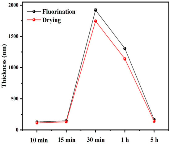
Figure 10.
Thickness of the fluoride layer of fluorinated and dried samples.
4. Conclusions
This study investigated the effects of direct fluorination using fluorine gas and subsequent drying on the surface properties and morphology of polyethylene terephthalate (PET) films. The PET films were fluorinated at room temperature and 660 torr for 10 min to 5 h, and some samples were further dried at 70°C for 7 d. Fourier-transform infrared (FT-IR) and X-ray photoelectron spectroscopy (XPS) analyses confirmed the incorporation of fluorine and the formation of -CHF- and -CF2- groups, with the degree of fluorination increasing with the reaction time. Excessive reactions led to CF4 formation and loss, and drying caused a further decrease in fluorine content. Fluorination increased the crystallinity of PET owing to increased polarity, whereas drying decreased the crystallinity due to increased crosslinking. The glass transition temperature increased after fluorination and drying, which was attributed to the increased polarity and crosslinking, respectively. The surface hydrophilicity of PET significantly increased with fluorination time, with the water contact angle decreasing to 3.35° owing to the introduction of polar fluorinated atoms and the development of a rough, porous surface morphology. Drying of the fluorinated samples led to an increase in the water contact angle, with a maximum of 85.95°, owing to increased crosslinking and particle formation on the surface. This study provides a novel approach for constructing controllable hydrophilic and hydrophobic surfaces using fluorination and drying, as shown in Figure 11. Hydrophilic PET surfaces are useful for dyeing and metal plating in composite applications. Furthermore, the hydrophobic surface combined with PET’s excellent chemical resistance can be used as a versatile waterproofing material.
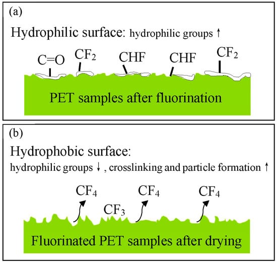
Figure 11.
Schematic of the PET surface after (a) fluorination and (b) drying.
Author Contributions
Z.H. performed the surface fluorination of all samples and wrote the manuscript. J.-H.K. conducted the XPS analysis of all samples and contributed to the writing of the manuscript. S.Y. performed FTIR analysis of all samples. The manuscript was written through the contributions of all authors. All authors have read and agreed to the published version of the manuscript.
Funding
This study received no external funding support.
Data Availability Statement
Data from this study may be obtained by contacting the corresponding author via email.
Conflicts of Interest
The authors declare no conflicts of interest.
References
- Welle, F. Twenty years of PET bottle to bottle recycling—An overview. Resour. Conserv. Recycl. 2011, 55, 865–875. [Google Scholar] [CrossRef]
- Archibald, A.T.; Parrish, D.D. A brief guidance on Polyethylene terephthalate. J. Ind. Environ. Chem. 2021, 5, 1–2. [Google Scholar]
- Ravindranath, K.; Mashelkar, R.A. Polyethylene terephthalate—I. Chemistry, thermodynamics and transport properties. Chem. Eng. Sci. 1986, 41, 2197–2214. [Google Scholar] [CrossRef]
- Ahmad, A.F.; Razali, A.R.; Razelan, I.S.M. Utilization of polyethylene terephthalate (PET) in asphalt pavement: A review. IOP Conf. Ser. Mater. Sci. Eng. 2017, 203, 012004. [Google Scholar] [CrossRef]
- Grumezescu, A.M.; Stoica, A.E.; Dima-Balcescu, M.S.; Chircov, C.; Gharbia, S.; Balta, C.; Rosu, M.; Herman, H.; Holban, A.M.; Ficai, A.; et al. Electrospun Polyethylene Terephthalate Nanofibers Loaded with Silver Nanoparticles: Novel Approach in Anti-Infective Therapy. J. Clin. Med. 2019, 8, 1039. [Google Scholar] [CrossRef]
- Gramada Pintilie, A.M.; Stoica Oprea, A.E.; Niculescu, A.G.; Birca, A.C.; Vasile, B.S.; Holban, A.M.; Mihaiescu, T.; Serban, A.I.; Ciceu, A.; Balta, C.; et al. Zinc Oxide-Loaded Recycled PET Nanofibers for Applications in Healthcare and Biomedical Devices. Polymers 2024, 17, 45. [Google Scholar] [CrossRef]
- Yang, L.; Chen, J.; Guo, Y.; Zhang, Z. Surface modification of a biomedical polyethylene terephthalate (PET) by air plasma. Appl. Surf. Sci. 2009, 255, 4446–4451. [Google Scholar] [CrossRef]
- Inagaki, N.; Narushim, K.; Tuchida, N.; Miyazaki, K. Surface characterization of plasma-modified poly(ethylene terephthalate) film surfaces. J. Polym. Sci. Part B Polym. Phys. 2004, 42, 3727–3740. [Google Scholar] [CrossRef]
- Ueda, M.; Kostov, K.G.; Beloto, A.F.; Leite, N.F.; Grigorov, K.G. Surface modification of polyethylene terephthalate by plasma immersion ion implantation. Surf. Coat. Technol. 2004, 186, 295–298. [Google Scholar] [CrossRef]
- Wang, J.; Huang, N.; Pan, C.J.; Kwok, S.C.H.; Yang, P.; Leng, Y.X.; Chen, J.Y.; Sun, H.; Wan, G.J.; Liu, Z.Y.; et al. Bacterial repellence from polyethylene terephthalate surface modified by acetylene plasma immersion ion implantation–deposition. Surf. Coat. Technol. 2004, 186, 299–304. [Google Scholar] [CrossRef]
- Kim, E.-Y.; Kong, J.-S.; An, S.-K.; Kim, H.-D. Surface modification of polymers and improvement of the adhesion between evaporated copper metal film and a polymer. I. Chemical modification of PET. J. Adhes. Sci. Technol. 2000, 14, 1119–1130. [Google Scholar] [CrossRef]
- Mostafavi, A.H.; Mishra, A.K.; Gallucci, F.; Kim, J.H.; Ulbricht, M.; Coclite, A.M.; Hosseini, S.S. Advances in surface modification and functionalization for tailoring the characteristics of thin films and membranes via chemical vapor deposition techniques. J. Appl. Polym. Sci. 2023, 140, e53720. [Google Scholar] [CrossRef]
- Flores, O.; Campillo, B.; Castillo, F.; Martínez, H.; Colín, J. Surface modification of polyethylene terephthalate (PET) by corona discharge plasma. J. Nucl. Phys. Mater. Sci. Radiat. Appl. 2021, 8, 129–134. [Google Scholar] [CrossRef]
- O’Hare, L.A.; Smith, J.A.; Leadley, S.R.; Parbhoo, B.; Goodwin, A.J.; Watts, J.F. Surface physico-chemistry of corona-discharge-treated poly(ethylene terephthalate) film. Surf. Interface Anal. 2002, 33, 617–625. [Google Scholar] [CrossRef]
- Gao, S.L.; Häßler, R.; Mäder, E.; Bahners, T.; Opwis, K.; Schollmeyer, E. Photochemical surface modification of PET by excimer UV lamp irradiation. Appl. Phys. B 2005, 81, 681–690. [Google Scholar] [CrossRef]
- Zhu, Z.; Kelley, M.J. Poly(ethylene terephthalate) surface modification by deep UV (172 nm) irradiation. Appl. Surf. Sci. 2004, 236, 416–425. [Google Scholar] [CrossRef]
- Demir, T.; Wei, L.; Nitta, N.; Yushin, G.; Brown, P.J.; Luzinov, I. Toward a Long-Chain Perfluoroalkyl Replacement: Water and Oil Repellency of Polyethylene Terephthalate (PET) Films Modified with Perfluoropolyether-Based Polyesters. ACS Appl. Mater. Interfaces 2017, 9, 24318–24330. [Google Scholar] [CrossRef] [PubMed]
- Cho, E.; Kim, M.; Park, J.S.; Lee, S.J. Plasma-Polymer-Fluorocarbon Thin Film Coated Nanostructured-Polyethylene Terephthalate Surface with Highly Durable Superhydrophobic and Antireflective Properties. Polymers 2020, 12, 1026. [Google Scholar] [CrossRef]
- Du, W.; Di, J. Sputter-deposited nanostructure of polymeric fluorocarbon coatings on polyethylene terephthalate fiber. Surf. Coat. Technol. 2007, 201, 5498–5501. [Google Scholar] [CrossRef]
- Cheng, T.-S.; Lin, H.-T.; Chuang, M.-J. Surface fluorination of polyethylene terephthalate films with RF plasma. Mater. Lett. 2004, 58, 650–653. [Google Scholar] [CrossRef]
- Liu, Y.; Chen, Q.; Du, X.; Li, L.; Li, P. Surface modification of polyethylene terephthalate films by direct fluorination. AIP Adv. 2018, 8, 125333. [Google Scholar] [CrossRef]
- Kim, J.-H.; Namie, M.; Yonezawa, S. Enhanced adhesion between polyethylene terephthalate and metal film by surface fluorination. Compos. Commun. 2018, 10, 205–208. [Google Scholar] [CrossRef]
- Kim, J.-H.; Umeda, H.; Ohe, M.; Yonezawa, S.; Takashima, M. Preparation of Pure LiPF6 Using Fluorine Gas at Room Temperature. Chem. Lett. 2011, 40, 360–361. [Google Scholar] [CrossRef]
- Chen, Z.; Hay, J.N.; Jenkins, M.J. FTIR spectroscopic analysis of poly(ethylene terephthalate) on crystallization. Eur. Polym. J. 2012, 48, 1586–1610. [Google Scholar] [CrossRef]
- Patterson, D.; Ward, I.M. The assignment of the carboxyl and hydroxyl absorptions in the infra-red spectrum of polyethylene terephthalate. Trans. Faraday Soc. 1957, 53, 291–294. [Google Scholar] [CrossRef]
- Kim, J.-H.; Mishina, T.; Namie, M.; Nishimura, F.; Yonezawa, S. Effects of surface fluorination on the dyeing of polycarbonate (PC) resin. J. Coat. Technol. Res. 2021, 19, 617–624. [Google Scholar] [CrossRef]
- He, T.; Wang, Y.; Jiang, Y.; Liu, Y.; Wang, X.; Luo, L.; Liu, X. Fluorination-generated uninterrupted gradient-refractive index on commercial flexible substrates for high broadband and omnidirectional transmittance. Appl. Surf. Sci. 2019, 489, 494–503. [Google Scholar] [CrossRef]
- Zhong, Z.K.; Zheng, S.X.; Mi, Y.L. High-pressure DSC study of thermal transitions of a poly(ethylene terephthalate)/carbon dioxide system. Polymer 1999, 40, 3829–3834. [Google Scholar] [CrossRef]
- Bell, M.S.; Borhan, A. A Volume-Corrected Wenzel Model. ACS Omega 2020, 5, 8875–8884. [Google Scholar] [CrossRef]
- Han, T.-Y.; Shr, J.-F.; Wu, C.-F.; Hsieh, C.-T. A modified Wenzel model for hydrophobic behavior of nanostructured surfaces. Thin Solid. Film. 2007, 515, 4666–4669. [Google Scholar] [CrossRef]
Disclaimer/Publisher’s Note: The statements, opinions and data contained in all publications are solely those of the individual author(s) and contributor(s) and not of MDPI and/or the editor(s). MDPI and/or the editor(s) disclaim responsibility for any injury to people or property resulting from any ideas, methods, instructions or products referred to in the content. |
© 2025 by the authors. Licensee MDPI, Basel, Switzerland. This article is an open access article distributed under the terms and conditions of the Creative Commons Attribution (CC BY) license (https://creativecommons.org/licenses/by/4.0/).