Stress–Strain Relationship of Rubberized Geopolymer Concrete with Slag and Fly Ash


Abstract
1. Introduction
2. Experimental Program
2.1. Materials
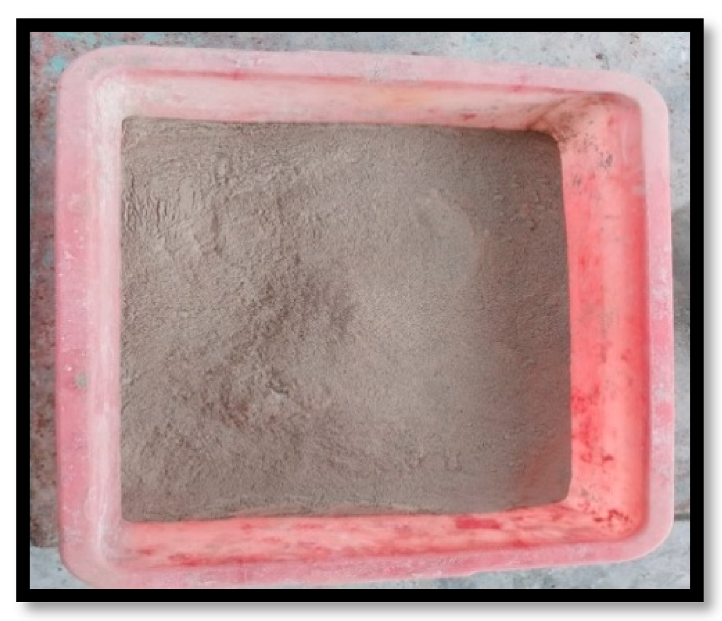
2.1.1. Binders
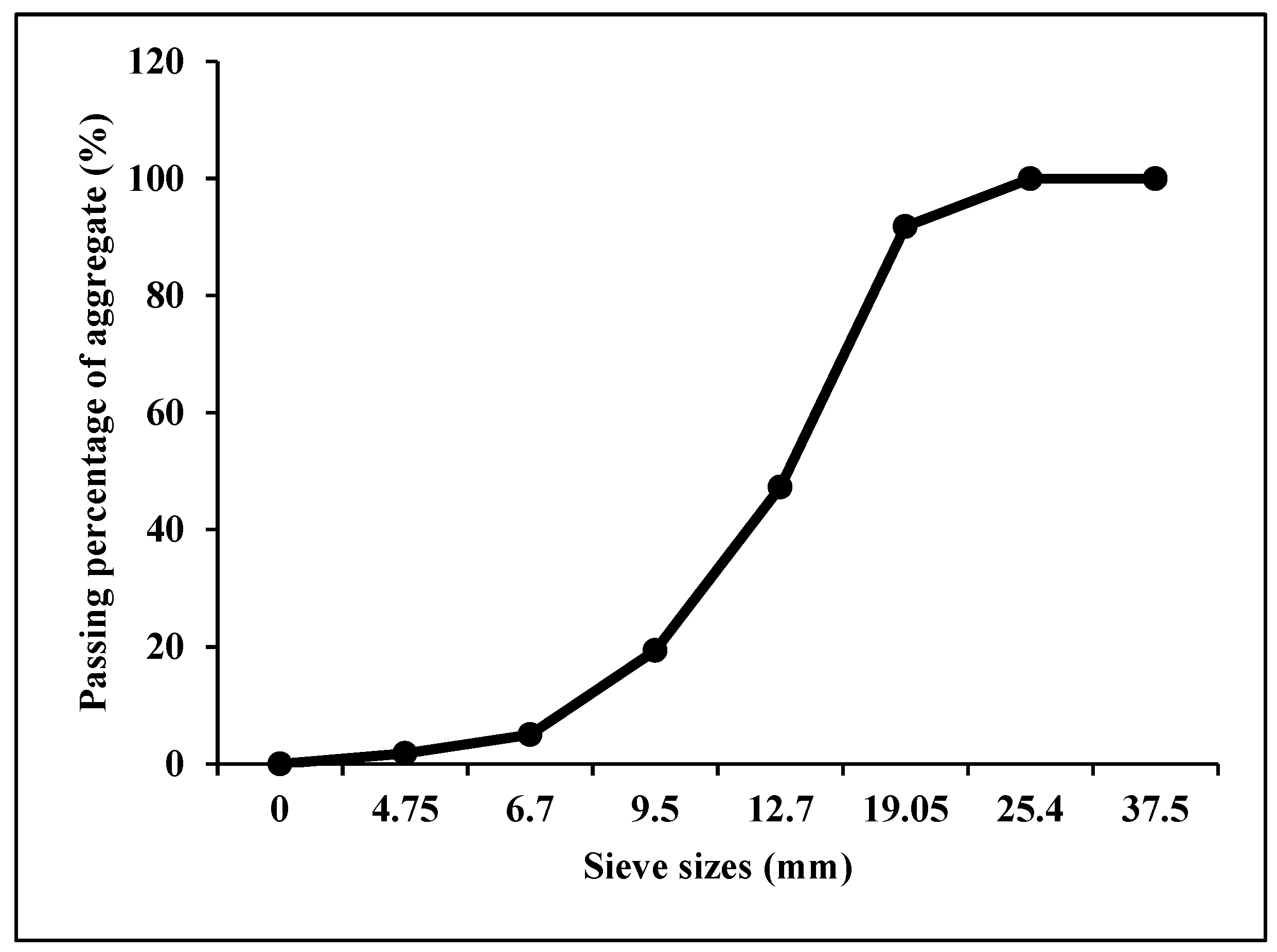
2.1.2. Aggregates
2.1.3. Alkaline Activator Solution (AAS)
2.1.4. Crumb Rubber Fine Aggregate
2.1.5. Superplasticizer
2.2. Concrete Preparation
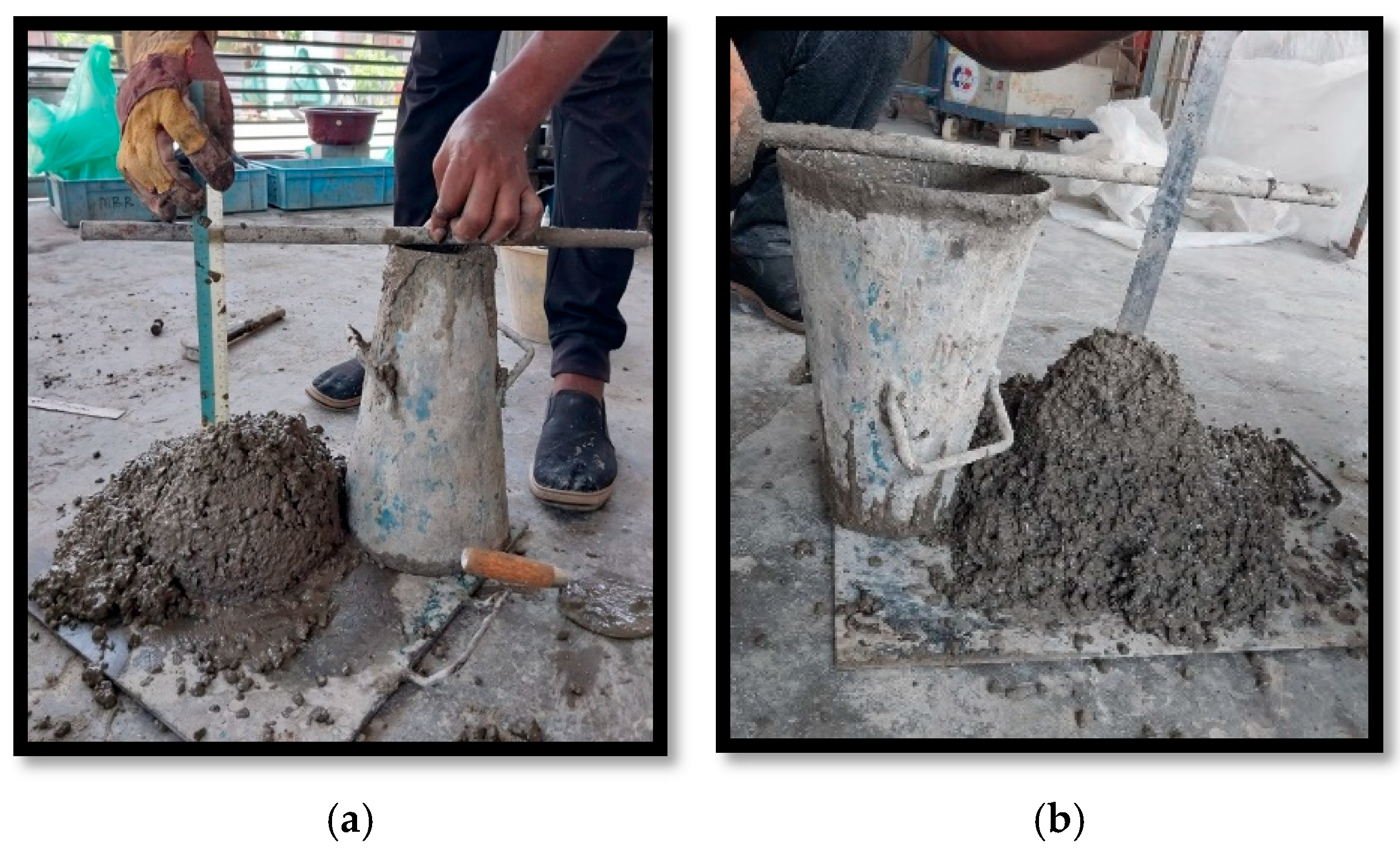
2.3. Slump Test
2.4. Compressive Strength Test
2.5. Modulus of Elasticity Test
3. Experimental Results and Discussions
3.1. Initial Setting Time of RuGPC
3.2. Workability
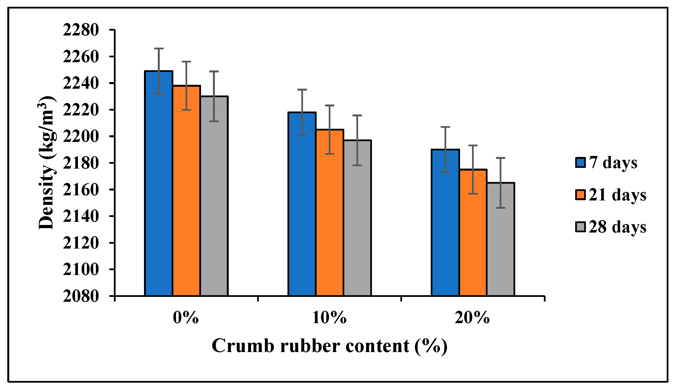
3.3. Density
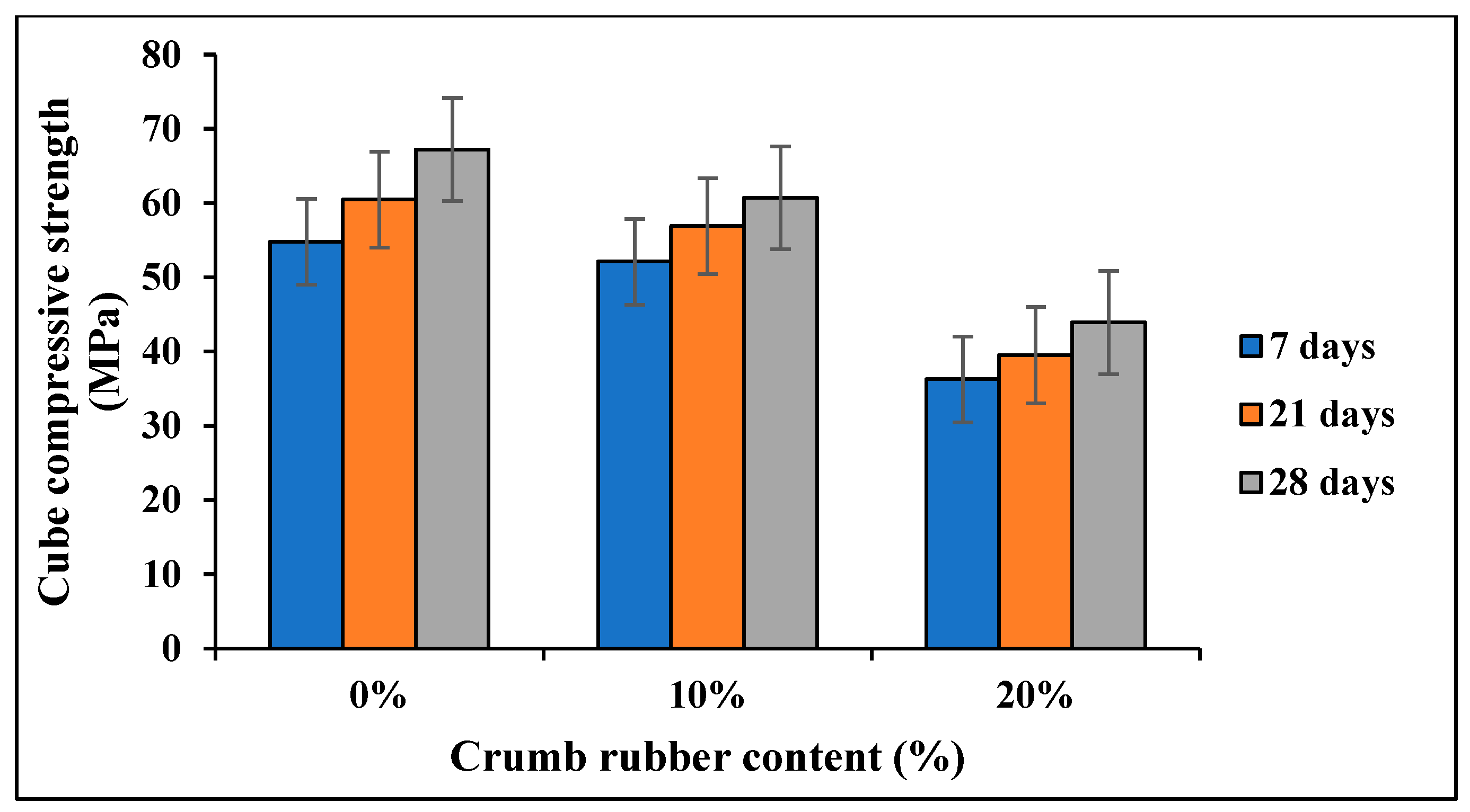
3.4. Cube Compressive Strength
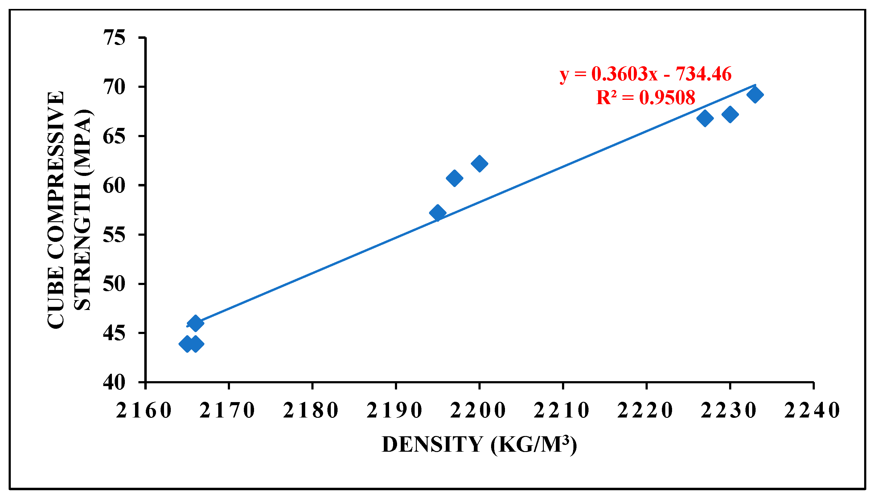
Correlation Between Density and 28-Day Cube Compressive Strength
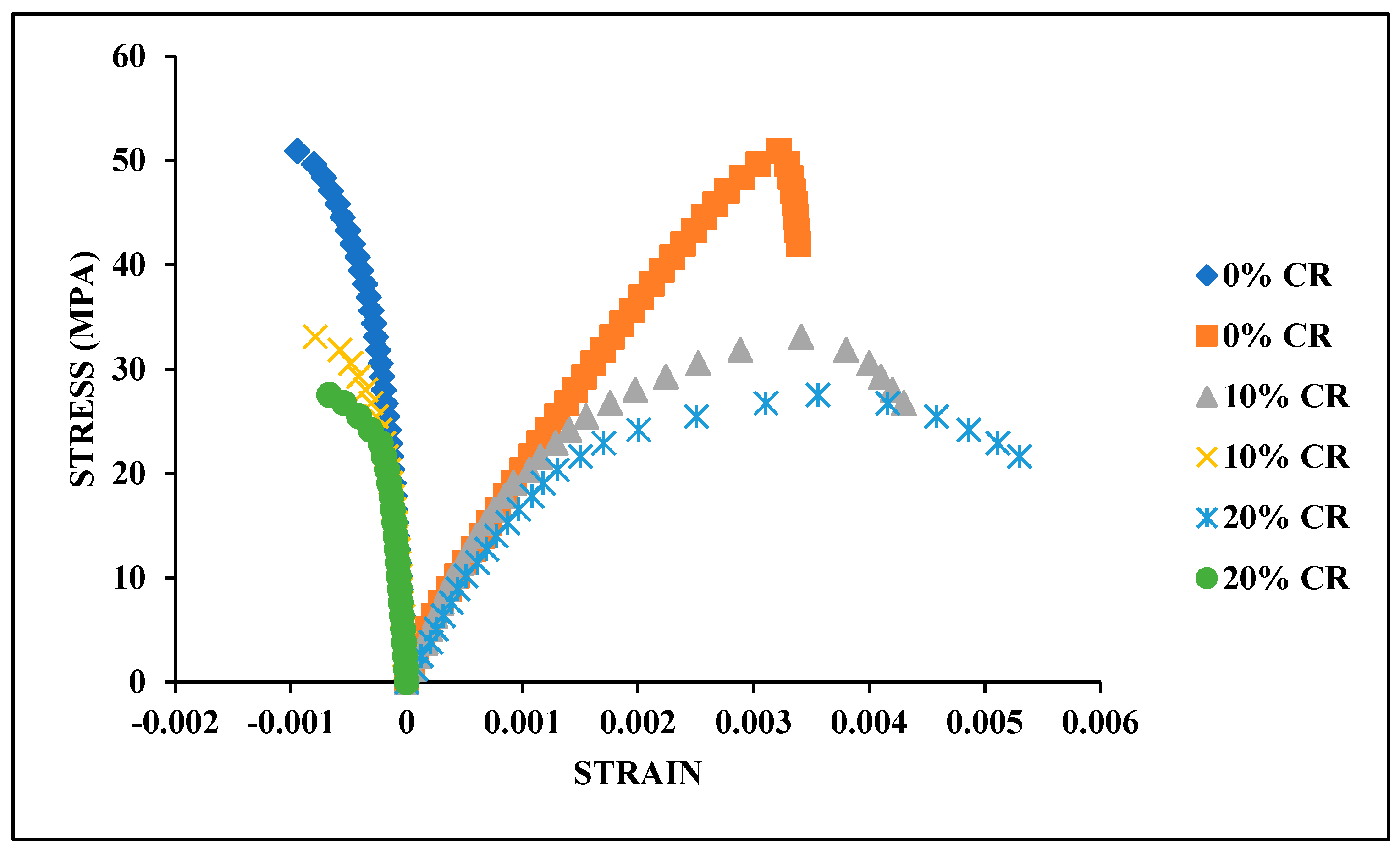
3.5. Stress–Strain Relationship
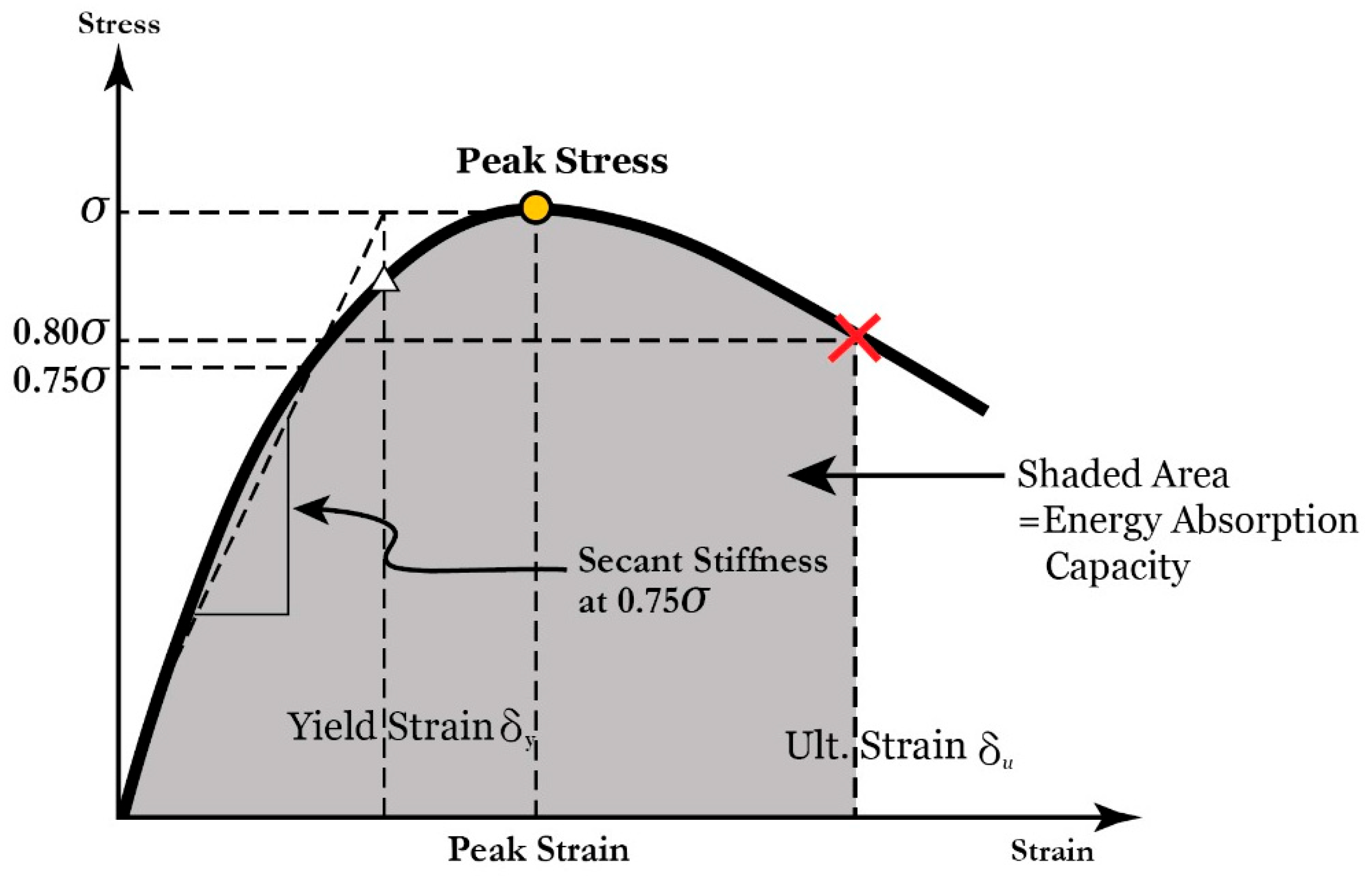
3.5.1. Peak Stress
3.5.2. Correlation Between the Cube and Cylinder Compressive Strength
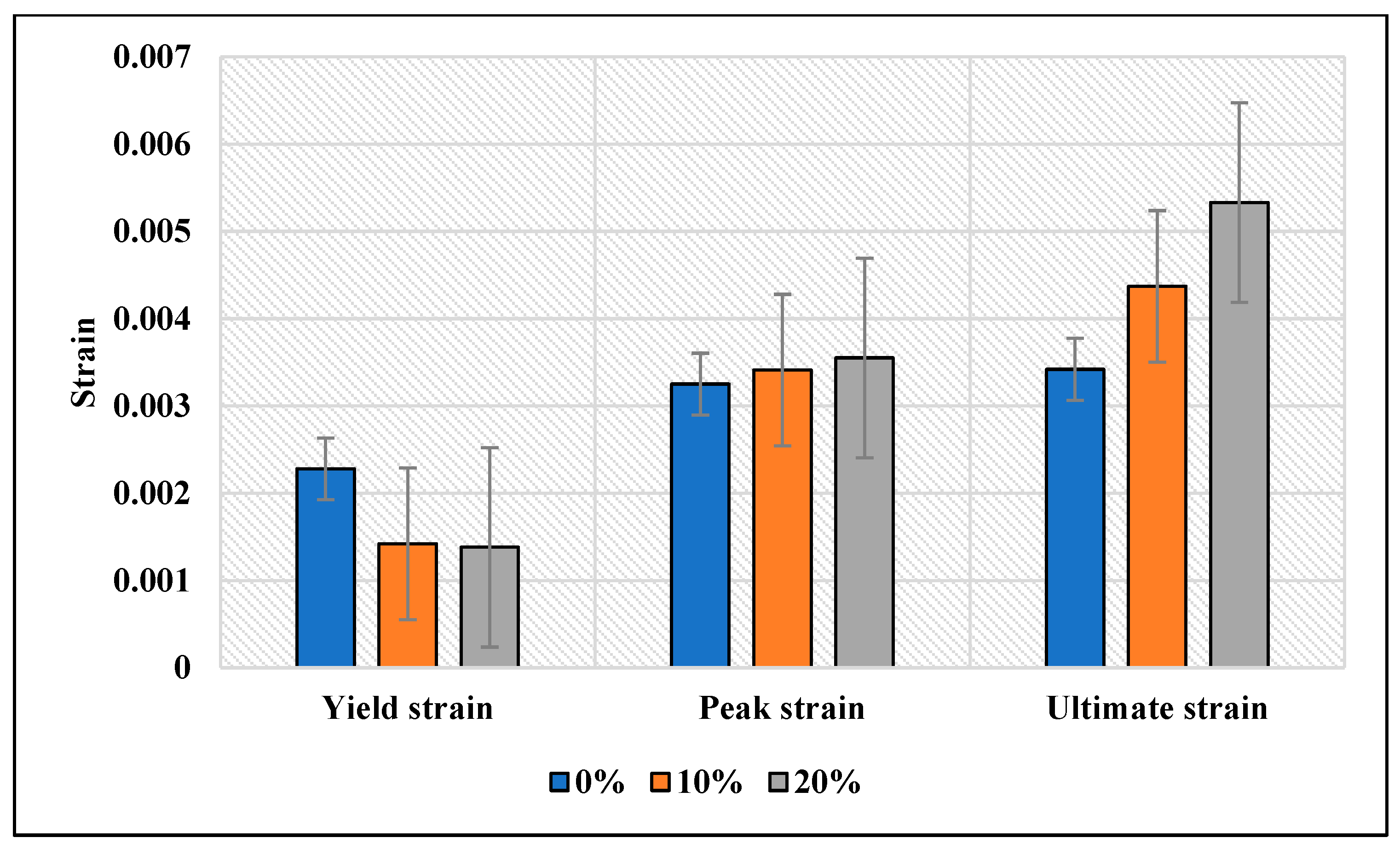
3.5.3. Strain Values
3.5.4. Modulus of Elasticity
3.5.5. Poisson’s Ratio
3.5.6. Toughness/Energy Absorption
3.5.7. Ductility Index
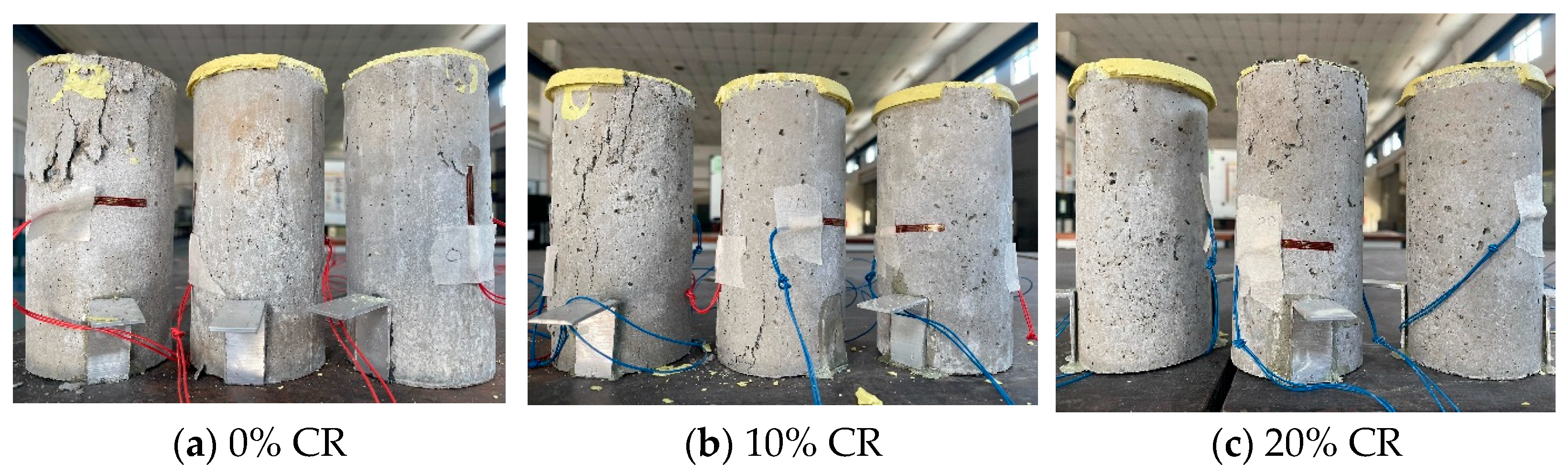
3.6. Failure Mode
4. Correlation with Standard Codes
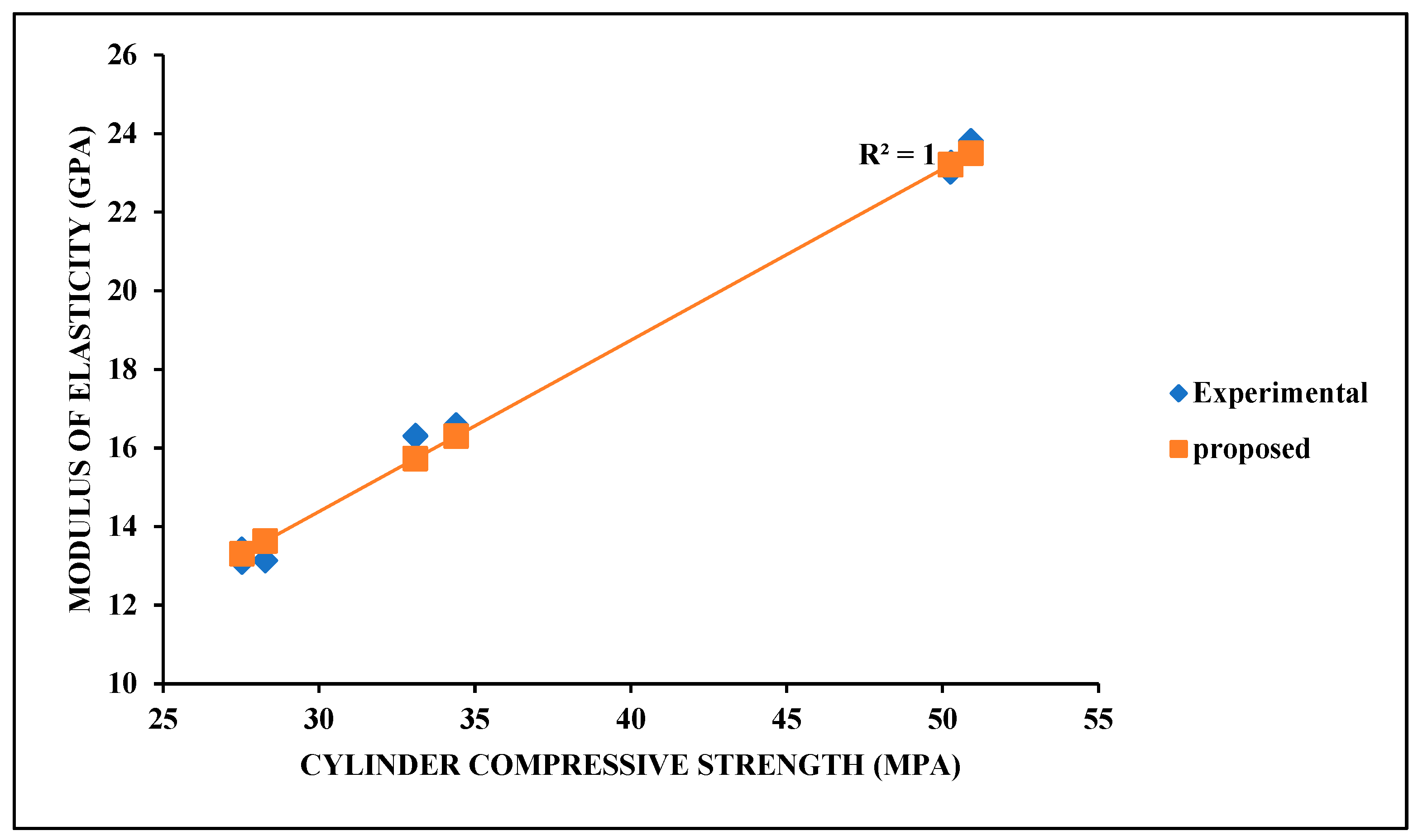
4.1. Modulus of Elasticity (MoE)
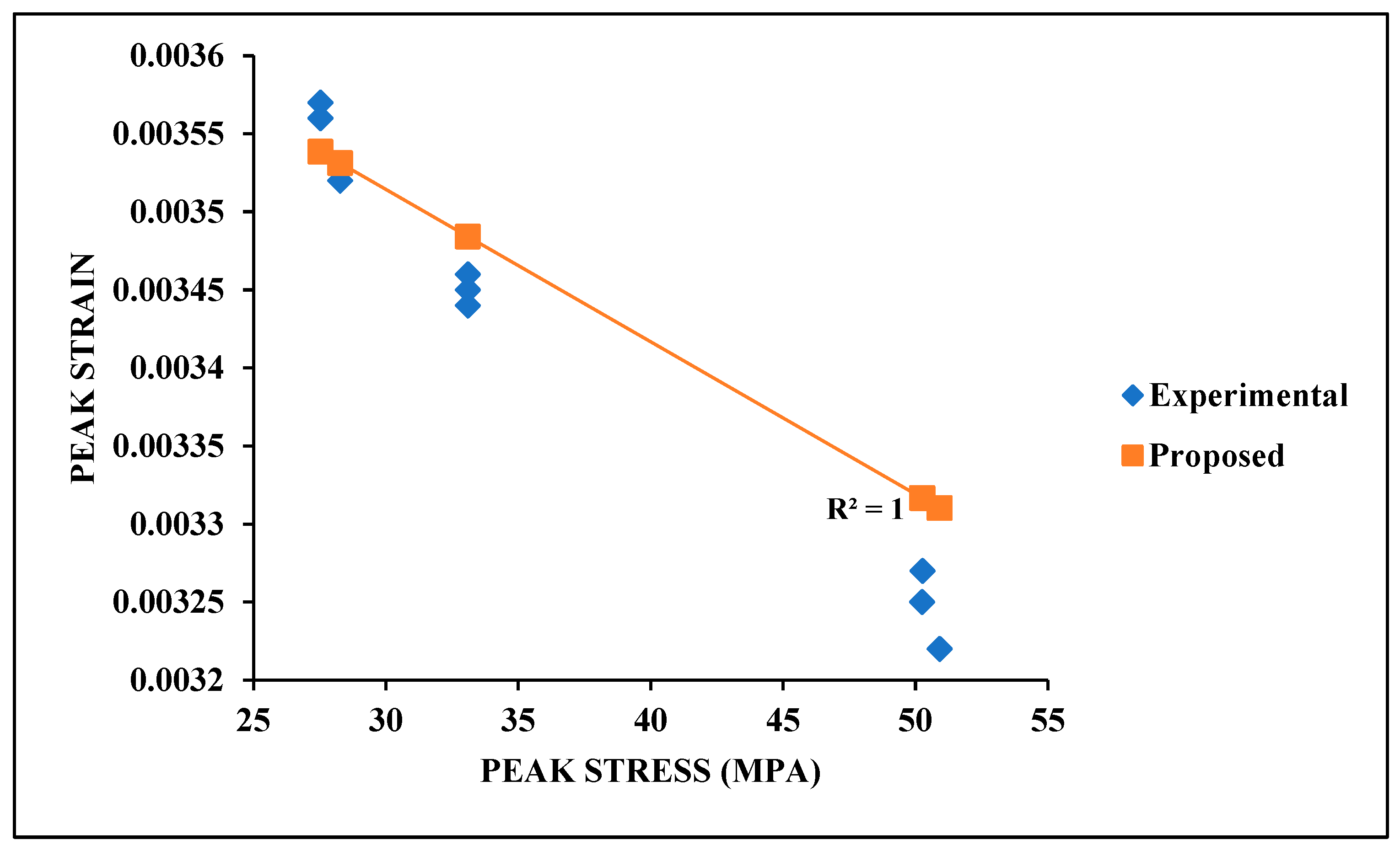
4.2. Peak Strain

| No. | Practical Results | Noushini et al. [149] | Hardjito et al. [97] | ||
|---|---|---|---|---|---|
| CS | MoE | Strain | Exp/Num | Exp/Num | |
| C001 | 50.265 | 23.265 | 0.0033 | 1.60 | 1.29 |
| C002 | 50.248 | 23.036 | 0.00328 | 1.59 | 1.28 |
| C003 | 50.910 | 23.818 | 0.00322 | 1.58 | 1.25 |
| C101 | 33.096 | 16.314 | 0.00346 | 1.32 | 1.57 |
| C102 | 33.089 | 16.581 | 0.00345 | 1.32 | 1.56 |
| C103 | 33.082 | 16.314 | 0.00344 | 1.32 | 1.56 |
| C201 | 27.274 | 13.422 | 0.00357 | 1.26 | 1.72 |
| C202 | 28.273 | 13.141 | 0.00352 | 1.26 | 1.68 |
| C203 | 27.252 | 13.11 | 0.00356 | 1.26 | 1.71 |
| AVG | - | - | 1.39 | 1.51 | |
| S. D | - | - | - | 0.15 | 0.19 |
| COV | - | - | - | 11.01 | 12.64 |
5. Proposed Models
5.1. Cube Compressive Strength
5.2. Modulus of Elasticity
5.3. Peak Strain
6. Conclusions
- The standard deviation between the experimental and numerical results of the modulus of elasticity proposed by this investigation, Noushini et al. (FA-GPC), and Hassan et al. (FA-GPC) was 0.14, 0.15, and 0.16, while that of the peak strain with respect to the peak stress was 0.08, 0.15, and 0.19. The average modulus of elasticity of metakalin-based GPC was 1.19, while that of FA-based RuGPC was 0.9 when predicted with the proposed experimental model. This implies that there is a strong correlation between the stress–strain parameters of RuGPC made with GGBFS/FA, FA, and Metakaolin.
- The peak strain and ultimate strain increased by 8.56% and 55.84%, respectively, when the percentage of CR was raised to 20%, which shows that rubberized geopolymer concrete has higher deformability characteristics. This quality of rubberized geopolymer concrete was confirmed when the Poisson’s ratio, toughness, and ductility index increased by 30.34%, 22.4%, and 156.67%. This makes rubberized geopolymer concrete very suitable for areas prone to vibration.
- The concrete slump, density, compressive strength, peak stress, and modulus of elasticity of RuGPC reduced by 8.33%, 2.91%, 34.67%, 44.97%, and 43.42%, respectively, at 20% addition of CR replacement compared to the control specimen. This implies that the use of rubber aggregate negatively affects concrete workability and load-bearing capacity.
- Numerical models were proposed for the cube compressive strength, modulus of elasticity, and peak strain of RuGPC at different percentages of crumb rubber. The findings demonstrate that the model’s predictions fit the experimental data quite well. The model’s calculated results, with R2 values of 0.9508, 0.9935, and 0.9762, show a high degree of consistency with the experimental data. Formulas proposed by Hassan et al. and Noushini et al. can also predict the modulus of elasticity of rubberized geopolymer concrete with a high degree of accuracy.
- The failure mode of geopolymer concrete with rubber aggregates showed fewer cracks, confirming the theory that rubber positively affects the energy absorption capacity and toughness of concrete. However, it reduces the workability and mechanical characteristics of concrete. It is paramount to balance the percentage of rubber in concrete with improved rubber pre-treatment to enable rubberized geopolymer concrete to attain the required workability and mechanical qualities while imposing its dominance in energy dissipation and toughness.
- The results show that rubberized geopolymer concrete can be used for the construction of structural elements subjected to lateral impact and where high energy absorption is required, e.g., columns in underground car parks and underneath bridges prone to vehicular collision, airport pavements, etc.
Author Contributions
Funding
Data Availability Statement
Acknowledgments
Conflicts of Interest
References
- Pourmohammadimojaveri, S. High Performance Rubber Concrete. Ph.D. Thesis, Sydney University, Sydney, Australia, 2019. [Google Scholar]
- Thomas, B.S.; Gupta, R.C.; Kalla, P.; Cseteneyi, L. Strength, abrasion and permeation characteristics of cement concrete containing discarded rubber fine aggregates. Constr. Build. Mater. 2014, 59, 204–212. [Google Scholar] [CrossRef]
- Yadav, J.S.; Tiwari, S.K. The impact of end-of-life tires on the mechanical properties of fine-grained soil: A Review. Environ. Dev. Sustain. 2019, 21, 485–568. [Google Scholar] [CrossRef]
- Sodupe-Ortega, E.; Fraile-Garcia, E.; Ferreiro-Cabello, J.; Sanz-Garcia, A. Evaluation of crumb rubber as aggregate for automated manufacturing of rubberized long hollow blocks and bricks. Constr. Build. Mater. 2016, 106, 305–316. [Google Scholar] [CrossRef]
- Rigotti, D.; Dorigato, A. Novel uses of recycled rubber in civil applications. Adv. Ind. Eng. Polym. Res. 2022, 5, 214–233. [Google Scholar] [CrossRef]
- Zhang, B.; Feng, Y.; Xie, J.; Lai, D.; Yu, T.; Huang, D. Rubberized geopolymer concrete: Dependence of mechanical properties and freeze-thaw resistance on replacement ratio of crumb rubber. Constr. Build. Mater. 2021, 310, 125248. [Google Scholar] [CrossRef]
- Ullah, H.; Iqbal, M.; Khan, K.; Jamal, A.; Nawaz, A.; Khan, N.; Jalal, F.E.; Almaliki, A.H.; Hussein, E.E. Experimental investigation of the stress–strain behavior and strength characterization of rubberized reinforced concrete. Materials 2022, 15, 730. [Google Scholar] [CrossRef]
- Jokar, F.; Khorram, M.; Karimi, G.; Hataf, N. Experimental investigation of mechanical properties of crumbed rubber concrete containing natural zeolite. Constr. Build. Mater. 2019, 208, 651–658. [Google Scholar] [CrossRef]
- He, S.; Jiang, Z.; Chen, H.; Chen, Z.; Ding, J.; Deng, H.; Mosallam, A.S. Mechanical properties, durability, and structural applications of rubber concrete: A state-of-the-art-review. Sustainability 2023, 15, 8541. [Google Scholar] [CrossRef]
- Han, Y.; Lv, Z.; Bai, Y.; Han, G.; Li, D. Experimental Study on the Mechanical Properties of Crumb Rubber Concrete after Elevated Temperature. Polymers 2023, 15, 3102. [Google Scholar] [CrossRef]
- Youssf, O.; Mills, J.E.; Benn, T.; Zhuge, Y.; Ma, X.; Roychand, R.; Gravina, R. Development of crumb rubber concrete for practical application in the residential construction sector—Design and processing. Constr. Build. Mater. 2020, 260, 119813. [Google Scholar] [CrossRef]
- Khaloo, A.R.; Dehestani, M.; Rahmatabadi, P. Mechanical properties of concrete containing a high volume of tire–rubber particles. Waste Manag. 2008, 28, 2472–2482. [Google Scholar] [CrossRef] [PubMed]
- Pacheco-Torgal, F.; Ding, Y.; Jalali, S. Properties and durability of concrete containing polymeric wastes (tyre rubber and polyethylene terephthalate bottles): An overview. Constr. Build. Mater. 2012, 30, 714–724. [Google Scholar] [CrossRef]
- Abd-Elaal, E.-S.; Araby, S.; Mills, J.E.; Youssf, O.; Roychand, R.; Ma, X.; Zhuge, Y.; Gravina, R.J. Novel approach to improve crumb rubber concrete strength using thermal treatment. Constr. Build. Mater. 2019, 229, 116901. [Google Scholar] [CrossRef]
- Chylík, R.; Trtík, T.; Fládr, J.; Bílý, P. Mechanical properties and durability of crumb rubber concrete. IOP Conf. Ser. Mater. Sci. Eng. 2017, 236, 012093. [Google Scholar] [CrossRef]
- Ganjian, E.; Khorami, M.; Maghsoudi, A.A. Scrap-tyre-rubber replacement for aggregate and filler in concrete. Constr. Build. Mater. 2009, 23, 1828–1836. [Google Scholar] [CrossRef]
- Pham, T.M.; Lim, Y.Y.; Malekzadeh, M. Effect of pre-treatment methods of crumb rubber on strength, permeability and acid attack resistance of rubberised geopolymer concrete. J. Build. Eng. 2021, 41, 102448. [Google Scholar]
- Dong, M.; Elchalakani, M.; Karrech, A.; Yang, B. Strength and durability of geopolymer concrete with high volume rubber replacement. Constr. Build. Mater. 2021, 274, 121783. [Google Scholar] [CrossRef]
- Shahzad, K.; Zhao, Z. Experimental study of NaOH pretreated crumb rubber as substitute of fine aggregate in concrete. Constr. Build. Mater. 2022, 358, 129448. [Google Scholar] [CrossRef]
- Rajagopal, M.R.; Bhavya, M.; Kumari, G.J. Study on the impact of pre-treatment method and admixture on the mechanical and durability properties of crumb rubber concrete. AIP Conf. Proc. 2024, 3010, 020010. [Google Scholar]
- Najim, K.B.; Hall, M.R. Crumb rubber aggregate coatings/pre-treatments and their effects on interfacial bonding, air entrapment and fracture toughness in self-compacting rubberised concrete (SCRC). Mater. Struct. 2013, 46, 2029–2043. [Google Scholar] [CrossRef]
- Raghavan, D.; Huynh, H.; Ferraris, C.F. Workability, mechanical properties, and chemical stability of a recycled tyre rubber-filled cementitious composite. J. Mater. Sci. 1998, 33, 1745–1752. [Google Scholar] [CrossRef]
- Lv, J.; Zhou, T.; Du, Q.; Wu, H. Effects of rubber particles on mechanical properties of lightweight aggregate concrete. Constr. Build. Mater. 2015, 91, 145–149. [Google Scholar] [CrossRef]
- Xie, J.-H.; Guo, Y.-C.; Liu, L.-S.; Xie, Z.-H. Compressive and flexural behaviours of a new steel-fibre-reinforced recycled aggregate concrete with crumb rubber. Constr. Build. Mater. 2015, 79, 263–272. [Google Scholar] [CrossRef]
- Li, L.; Ruan, S.; Zeng, L. Mechanical properties and constitutive equations of concrete containing a low volume of tire rubber particles. Constr. Build. Mater. 2014, 70, 291–308. [Google Scholar] [CrossRef]
- Zheng, L.; Huo, X.S.; Yuan, Y. Experimental investigation on dynamic properties of rubberized concrete. Constr. Build. Mater. 2008, 22, 939–947. [Google Scholar] [CrossRef]
- Luhar, S.; Chaudhary, S.; Luhar, I. Development of rubberized geopolymer concrete: Strength and durability studies. Constr. Build. Mater. 2019, 204, 740–753. [Google Scholar] [CrossRef]
- Prachasaree, W.; Limkatanyu, S.; Hawa, A.; Samakrattakit, A. Development of equivalent stress block parameters for fly-ash-based geopolymer concrete. Arab. J. Sci. Eng. 2014, 39, 8549–8558. [Google Scholar] [CrossRef]
- Hassan, K.; Ibrahim, M.I.; Shill, S.K.; Al-Deen, S. Mechanical Properties of Rubberised Geopolymer Concrete. Materials 2024, 17, 1031. [Google Scholar] [CrossRef]
- Hognestad, E. Study of Combined Bending and Axial Load in Reinforced Concrete Members; University of Illinois: Champaign, IL, USA, 1951; Engineering Experiment Station, Bulletin no. 399. [Google Scholar]
- Thomas, R.J.; Peethamparan, S. Alkali-activated concrete: Engineering properties and stress–strain behavior. Constr. Build. Mater. 2015, 93, 49–56. [Google Scholar] [CrossRef]
- Davidovits, J. False values on CO2 emission for geopolymer cement/concrete published in scientific papers. Tech. Pap. 2015, 24, 1–9. [Google Scholar]
- Shill, S.K.; Al-Deen, S.; Ashraf, M.; Hutchison, W. Resistance of fly ash based geopolymer mortar to both chemicals and high thermal cycles simultaneously. Constr. Build. Mater. 2020, 239, 117886. [Google Scholar] [CrossRef]
- Vora, P.R.; Dave, U.V. Parametric studies on compressive strength of geopolymer concrete. Procedia Eng. 2013, 51, 210–219. [Google Scholar] [CrossRef]
- Giri, Y.G.A.L.P.; Mohammed, B.S.; Liew, M.S.; Zawawi, N.A.W.A.; Abdulkadir, I.; Singh, P.; Ravindran, G. Mechanical and Microstructural Properties of Rubberized Geopolymer Concrete: Modeling and Optimization. Buildings 2023, 13, 2021. [Google Scholar] [CrossRef]
- Moghaddam, S.C.; Madandoust, R.; Jamshidi, M.; Nikbin, I.M. Mechanical properties of fly ash-based geopolymer concrete with crumb rubber and steel fiber under ambient and sulfuric acid conditions. Constr. Build. Mater. 2021, 281, 122571. [Google Scholar] [CrossRef]
- ASTM C136-06; Standard Test Method for Sieve Analysis of Fine and Coarse Aggregates. American Society for Testing and Materials: Philadelphia, PA, USA, 2006.
- ASTM C33/C33M-18; Standard Specification for Concrete Aggregates. American Society for Testing and Materials: Philadelphia, PA, USA, 2003.
- ASTM C494; Standard Specification for Chemical Admixtures for Concrete. American Society for Testing and Materials: Philadelphia, PA, USA, 2013. Available online: www.concrete.org (accessed on 15 August 2024).
- Pavithra, P.; Reddy, M.S.; Dinakar, P.; Rao, B.H.; Satpathy, B.; Mohanty, A. A mix design procedure for geopolymer concrete with fly ash. J. Clean. Prod. 2016, 133, 117–125. [Google Scholar] [CrossRef]
- EN 206-1; Part 1: Method of Specifying and Guidiance for Specifier. CEN European Committee for Standardization: Brussels, Belgium, 2006.
- EN 12350-2: 2009; Testing Fresh Concrete. Slump-Test. British Standards: London, UK, 2009.
- EN 12390-4; Testing Hardened Concrete, Compressive Strength, Specification for Testing Machines. British Standards: London, UK, 2025.
- Narayanan, R.S. Concise Eurocode 2: For the Design of In-Situ Concrete Framed Buildings to BS EN 1992-1-1: 2004 and Its UK National Annex: 2005; A Cement and Concrete Industry Publication MPA; The Concrete Centre: London, UK, 2006. [Google Scholar]
- Chindaprasirt, P.; Ridtirud, C. High calcium fly ash geopolymer containing natural rubber latex as additive. GEOMATE J. 2020, 18, 124–129. [Google Scholar] [CrossRef]
- Arunkumar, K.; Muthukannan, M.; Kumar, A.S.; Ganesh, A.C. Mitigation of waste rubber tire and waste wood ash by the production of rubberized low calcium waste wood ash based geopolymer concrete and influence of waste rubber fibre in setting properties and mechanical behavior. Environ. Res. 2021, 194, 110661. [Google Scholar] [CrossRef]
- Azunna, S.U.; Aziz, F.N.A.B.A.; Al-Ghazali, N.A.; Rashid, R.S.; Bakar, N.A. Review on the mechanical properties of rubberized geopolymer concrete. Clean. Mater. 2024, 11, 100225. [Google Scholar] [CrossRef]
- Elzeadani, M.; Bompa, D.; Elghazouli, A. Preparation and properties of rubberised geopolymer concrete: A review. Constr. Build. Mater. 2021, 313, 125504. [Google Scholar] [CrossRef]
- Luhar, S.; Luhar, I.; Nicolaides, D.; Gupta, R. Durability performance evaluation of rubberized geopolymer concrete. Sustainability 2021, 13, 5969. [Google Scholar] [CrossRef]
- Puligilla, S.; Chen, X.; Mondal, P. Understanding the role of silicate concentration on the early-age reaction kinetics of a calcium containing geopolymeric binder. Constr. Build. Mater. 2018, 191, 206–215. [Google Scholar] [CrossRef]
- Criado, M.; Fernández-Jiménez, A.; Palomo, A. Alkali activation of fly ash: Effect of the SiO2/Na2O ratio: Part I: FTIR study. Microporous Mesoporous Mater. 2007, 106, 180–191. [Google Scholar] [CrossRef]
- Sanyin, Z.; Qijun, Y.; Fei, Q.; Jiaqi, H.; Suhong, Y.; Ziyun, W.; Guobang, G. Setting and strength characteristics of alkali-activated carbonatite cementitious materials with ground slag replacement. J. Wuhan Univ. Technol. Sci. Ed. 2006, 21, 125–128. [Google Scholar] [CrossRef]
- Su, D.-Y.; Pang, J.-Y.; Han, C.-Y.; Huang, J.-Y.; Hu, X.-Y.; Shi, W. Influence of basalt/polypropylene fiber on permeability and uniaxial compressive properties of waste tire rubberized concrete. Materials 2023, 16, 481. [Google Scholar] [CrossRef]
- Abdelaleem, A.; Moawad, M.; El-Emam, H.; Salim, H.; Sallam, H. Long term behavior of rubberized concrete under static and dynamic loads. Case Stud. Constr. Mater. 2024, 20, e03087. [Google Scholar] [CrossRef]
- Fadiel, A.A.M.; Abu-Lebdeh, T.; Munteanu, I.S.; Niculae, E.; Petrescu, F.I.T. Mechanical Properties of Rubberized Concrete at Elevated Temperatures. J. Compos. Sci. 2023, 7, 283. [Google Scholar] [CrossRef]
- Raffoul, S.; Garcia, R.; Pilakoutas, K.; Guadagnini, M.; Medina, N.F. Optimisation of rubberised concrete with high rubber content: An experimental investigation. Constr. Build. Mater. 2016, 124, 391–404. [Google Scholar] [CrossRef]
- Uygunoğlu, T.; Topçu, I.B. The role of scrap rubber particles on the drying shrinkage and mechanical properties of self-consolidating mortars. Constr. Build. Mater. 2010, 24, 1141–1150. [Google Scholar] [CrossRef]
- Guo, S.; Dai, Q.; Si, R.; Sun, X.; Lu, C. Evaluation of properties and performance of rubber-modified concrete for recycling of waste scrap tire. J. Clean. Prod. 2017, 148, 681–689. [Google Scholar] [CrossRef]
- AbdelAleem, B.H.; Ismail, M.K.; Hassan, A.A. The combined effect of crumb rubber and synthetic fibers on impact resistance of self-consolidating concrete. Constr. Build. Mater. 2018, 162, 816–829. [Google Scholar] [CrossRef]
- Siddique, R.; Naik, T.R. Properties of concrete containing scrap-tire rubber—An overview. Waste Manag. 2004, 24, 563–569. [Google Scholar] [CrossRef] [PubMed]
- Mhaya, A.M.; Shahidan, S.; Goel, A.; Huseien, G.F. Effect of metakaolin content and shape design on strength performance of lightweight rubberized geopolymer mortars incorporated slag-waste glass powders. Constr. Build. Mater. 2024, 432, 136500. [Google Scholar] [CrossRef]
- Adebayo, I.W.; Long, G.; Tang, Z.; Ghone, M.O.; Zaland, S.; Garba, M.J.; Yang, K.; Akhunzada, K.; Oluwasina, U.A. Effect of crumb rubber and polyethylene fiber on the strength and toughness of fly ash/slag-based geo-polymer concrete. Constr. Build. Mater. 2024, 455, 139133. [Google Scholar] [CrossRef]
- Aslani, F.; Ma, G.; Wan, D.L.Y.; Le, V.X.T. Experimental investigation into rubber granules and their effects on the fresh and hardened properties of self-compacting concrete. J. Clean. Prod. 2018, 172, 1835–1847. [Google Scholar] [CrossRef]
- Al-Fasih, M.Y.M.; Huseien, G.F.; bin Ibrahim, I.S.; Sam, A.R.M.; Algaifi, H.A.; Alyousef, R. Synthesis of rubberized alkali-activated concrete: Experimental and numerical evaluation. Constr. Build. Mater. 2021, 303, 124526. [Google Scholar] [CrossRef]
- Taha, M.R.; El-Dieb, A.; Abd El-Wahab, M. Fracture toughness of concrete incorporating rubber tire particles. In International Conference on Performance of Construction Materials: A New Era of Building, Proceedings of the International Conference on Performance of Construction Materials in the New Millennium (ICPCM), Cairo, Egypt, 18–20 February 2003; Elmaarefa: Cairo, Egypt, 2003; pp. 18–20. [Google Scholar]
- Fallah, S.; Nematzadeh, M. Mechanical properties and durability of high-strength concrete containing macro-polymeric and polypropylene fibers with nano-silica and silica fume. Constr. Build. Mater. 2017, 132, 170–187. [Google Scholar] [CrossRef]
- Manimaran, A.; Somasundaram, M.; Ravichandran, P.T. Experimental study on partial replacement of coarse aggregate by bamboo and fine aggregate by quarry dust in concrete. Int. J. Civ. Eng. Technol. 2017, 8, 1019–1027. [Google Scholar]
- Patil, S.; Vaidya, R.; Math, V. Effect of curing compounds on strength and durability of concrete mixes. Int. Res. J. Eng. Technol. (IRJET) 2016, 3, 2874–2879. [Google Scholar]
- Ephraim, M.E.; ThankGod, O.; Ezekwem, G.O. Performance Evaluation of Laterite Rock Concrete in Aggressive Environment. Am. J. Eng. Res. (AJER) 2018, 7, 93–101. [Google Scholar]
- Gornale, A.; Quadri, S.I.; Quadri, S.M.; Ali, S.M.A.; Hussaini, S.S. Strength aspects of glass fibre reinforced concrete. Int. J. Sci. Eng. Res. 2012, 3, 1–5. [Google Scholar]
- Okoye, F.; Durgaprasad, J.; Singh, N. Effect of silica fume on the mechanical properties of fly ash based-geopolymer concrete. Ceram. Int. 2016, 42, 3000–3006. [Google Scholar] [CrossRef]
- Qureshi, M.; Li, J.; Wu, C.; Sheng, D. Mechanical strength of rubberized concrete: Effects of rubber particle size, content, and waste fibre reinforcement. Constr. Build. Mater. 2024, 444, 137868. [Google Scholar] [CrossRef]
- Mansourghanaei, M.; Biklaryan, M.; Mardookhpour, A. Durability and mechanical properties of granulated blast furnace slag based geopolymer concrete containing polyolefin fibers and nano silica. KSCE J. Civ. Eng. 2024, 28, 209–219. [Google Scholar] [CrossRef]
- Raheem, A.A.; Soyingbe, A.A.; Emenike, A.J. Effect of curing methods on density and compressive strength of concrete. Int. J. Appl. Sci. Technol. 2013, 3, 55–64. [Google Scholar]
- Yahya, Z.; Abdullah, M.M.A.B.; Ramli, S.N.H.; Minciuna, M.G.; Razak, R.A. Durability of Fly Ash Based Geopolymer Concrete Infilled with Rubber Crumb in Seawater Exposure. IOP Conf. Ser. Mater. Sci. Eng. 2018, 374, 012069. [Google Scholar] [CrossRef]
- Opara, H.E.; Eziefula, U.G.; Eziefula, B.I. Comparison of physical and mechanical properties of river sand concrete with quarry dust concrete. Sel. Sci. Pap. J. Civ. Eng. 2018, 13, 127–134. [Google Scholar] [CrossRef]
- Azmi, A.A.; Abdullah, M.M.A.B.; Ghazali, C.M.R.; Ahmad, R.; Musa, L.; Rou, L.S. The Effect of Different Crumb Rubber Loading on the Properties of Fly Ash-Based Geopolymer Concrete. IOP Conf. Ser. Mater. Sci. Eng. 2019, 551, 012079. [Google Scholar] [CrossRef]
- Al Obeidy, N.F.; Khalil, W.I. Properties of modified metakaolin-based geopolymer concrete with crumbed rubber waste from damaged car tires. Res. Eng. Struct. Mater. 2024, 10, 209–231. [Google Scholar] [CrossRef]
- Lu, S.; Yang, J.; Wang, J.; Huang, L.; Wang, L. Behavior of steel tubed rubberized geopolymer concrete columns under axial compression: Experimental study and analytical modeling. Eng. Struct. 2024, 302, 117389. [Google Scholar] [CrossRef]
- Yang, G.; Chen, X.; Xu, J. Molecular dynamics simulation of interfacial mechanical properties of crumb rubber concrete. Constr. Build. Mater. 2024, 438, 137336. [Google Scholar] [CrossRef]
- Zhao, J.; Xie, J.; Wu, J.; Zhao, C.; Zhang, B. Workability, compressive strength, and microstructures of one-part rubberized geopolymer mortar. J. Build. Eng. 2023, 68, 106088. [Google Scholar] [CrossRef]
- Kuang, F.; Long, Z.; Kuang, D.; Guo, R.; Sun, J. Experimental study on high temperatures performance of rubberized geo-polymer mortar. J. Build. Eng. 2023, 76, 107091. [Google Scholar] [CrossRef]
- Roychand, R.; Gravina, R.J.; Zhuge, Y.; Ma, X.; Youssf, O.; Mills, J.E. A comprehensive review on the mechanical properties of waste tire rubber concrete. Constr. Build. Mater. 2020, 237, 117651. [Google Scholar] [CrossRef]
- Reda Taha, M.M.; El-Dieb, A.S.; Abd El-Wahab, M.A.; Abdel-Hameed, M.E. Mechanical, fracture, and microstructural investigations of rubber concrete. J. Mater. Civ. Eng. 2008, 20, 640–649. [Google Scholar] [CrossRef]
- Güneyisi, E.; Gesoğlu, M.; Özturan, T. Properties of rubberized concretes containing silica fume. Cem. Concr. Res. 2004, 34, 2309–2317. [Google Scholar] [CrossRef]
- Yasser, N.; Abdelrahman, A.; Kohail, M.; Moustafa, A. Experimental investigation of durability properties of rubberized concrete. Ain Shams Eng. J. 2023, 14, 102111. [Google Scholar] [CrossRef]
- Liang, K.X.; Wang, Q.C.; Zhang, K.; Zhang, R.L.; Cui, X.N.; Wang, B.Z. Effect of pore structure of air-entrained concrete on strength and impermeability at low temperature (3 °C) condition. Bull. Chin. Ceram. Soc. 2018, 37, 6. [Google Scholar]
- Lü, Q.; Qiu, Q.; Zheng, J.; Wang, J.; Zeng, Q. Fractal dimension of concrete incorporating silica fume and its correlations to pore structure, strength and permeability. Constr. Build. Mater. 2019, 228, 116986. [Google Scholar] [CrossRef]
- Alaneme, G.U.; Olonade, K.A.; Esenogho, E.; Lawan, M.M. Proposed simplified methodological approach for designing geopolymer concrete mixtures. Sci. Rep. 2024, 14, 15191. [Google Scholar] [CrossRef]
- Manzoor, T.; Bhat, J.A.; Shah, A.H. Advancements in geopolymer concrete: A state-of-the-art analysis of its mechanical and durability features. Iran. J. Sci. Technol. Trans. Civ. Eng. 2024, 48, 1777–1816. [Google Scholar] [CrossRef]
- Kanagaraj, B.; Kiran, T.; N, A.; Al Jabri, K.; S, J. Development and strength assessment of eco-friendly geopolymer concrete made with natural and recycled aggregates. Constr. Innov. 2023, 23, 524–545. [Google Scholar] [CrossRef]
- Azunna, S.U.; Aziz, F.N.A.A.; Abu Bakar, N.; Nasir, N.A.M. Mechanical properties of concrete with coconut shell as partial replacement of aggregates. IOP Conf. Ser. Mater. Sci. Eng. 2018, 431, 032001. [Google Scholar] [CrossRef]
- Azunna, S.U. Compressive strength of concrete with palm kernel shell as a partial replacement for coarse aggregate. SN Appl. Sci. 2019, 1, 342. [Google Scholar] [CrossRef]
- Azunna, S.U.; Aziz, F.N.A.A.; Cun, P.M.; Elhibir, M.M.O. Characterization of lightweight cement concrete with partial replacement of coconut shell fine aggregate. SN Appl. Sci. 2019, 1, 649. [Google Scholar] [CrossRef]
- Wang, J.; Guo, Z.; Yuan, Q.; Zhang, P.; Fang, H. Effects of ages on the ITZ microstructure of crumb rubber concrete. Constr. Build. Mater. 2020, 254, 119329. [Google Scholar] [CrossRef]
- Wallah, S.E.; Rangan, B.V. Low-Calcium Fly Ash-Based Geopolymer Concrete: Long-Term Properties; Faculty of Engineering, Curtin University of Technology: Perth, Australia, 2006. [Google Scholar]
- Wallah, S.E.; Hardjito, D.; Wallah, S.E.; Sumajouw, D.M.J.; Rangan, B.V. Introducing Fly Ash-Based Geopolymer Concrete: Manufacture and Engineering Properties. 2005. Available online: https://www.researchgate.net/publication/43649846 (accessed on 17 August 2024).
- Luhar, S. Fly Ash and Slag Based Geopolymer Concrete: Experimental Facts; LAP Lambert Academic Publishing: Saarbrücken, Germany, 2016. [Google Scholar]
- Lin, J.-X.; Liu, R.-A.; Liu, L.-Y.; Zhuo, K.-Y.; Chen, Z.-B.; Guo, Y.-C. High-strength and high-toughness alkali-activated composite materials: Optimizing mechanical properties through synergistic utilization of steel slag, ground granulated blast furnace slag, and fly ash. Constr. Build. Mater. 2024, 422, 135811. [Google Scholar] [CrossRef]
- Shen, Q.; Liu, J.; Li, Z.; Huang, S.; Wang, L.; Li, J.; Wu, X.; Song, W.; Li, L. Study on the early structural strength of a hardened GGBFS-based plugging slurry activated by alkali. Constr. Build. Mater. 2024, 433, 136586. [Google Scholar] [CrossRef]
- Sundararaj, J.B.; Rajkumar, P.R.K. Effects of multiple precursors on strength, durability, and microstructural properties of ambiently cured geopolymer concrete. Constr. Build. Mater. 2024, 442, 137538. [Google Scholar]
- Pradhan, J.; Panda, S.; Dwibedy, S.; Pradhan, P.; Panigrahi, S.K. Production of durable high-strength self-compacting geopolymer concrete with GGBFS as a precursor. J. Mater. Cycles Waste Manag. 2024, 26, 529–551. [Google Scholar] [CrossRef]
- Oinam, Y.; Yonis, A.; Bae, Y.; Lee, C.; Pyo, S. Effect of curing temperature on hydration characteristics of GGBFS-based cementless high-strength concrete. J. Build. Eng. 2024, 96, 110514. [Google Scholar] [CrossRef]
- Elyamany, H.E.; Elmoaty, A.E.M.A.; Diab, A.R.A. Properties of slag geopolymer concrete modified with fly ash and silica fume. Can. J. Civ. Eng. 2022, 49, 183–191. [Google Scholar] [CrossRef]
- Özkılıç, Y.O.; Çelik, A.I.; Tunç, U.; Karalar, M.; Deifalla, A.; Alomayri, T.; Althoey, F. The use of crushed recycled glass for alkali activated fly ash based geopolymer concrete and prediction of its capacity. J. Mater. Res. Technol. 2023, 24, 8267–8281. [Google Scholar] [CrossRef]
- Amin, M.; Elsakhawy, Y.; Abu el-Hassan, K.; Abdelsalam, B.A. Behavior evaluation of sustainable high strength geopolymer concrete based on fly ash, metakaolin, and slag. Case Stud. Constr. Mater. 2022, 16, e00976. [Google Scholar] [CrossRef]
- Hamed, Y.R.; Elshikh, M.M.Y.; Elshami, A.A.; Matthana, M.H.; Youssf, O. Mechanical properties of fly ash and silica fume based geopolymer concrete made with magnetized water activator. Constr. Build. Mater. 2024, 411, 134376. [Google Scholar] [CrossRef]
- Singh, R.P.; Vanapalli, K.R.; Jadda, K.; Mohanty, B. Durability assessment of fly ash, GGBS, and silica fume based geo-polymer concrete with recycled aggregates against acid and sulfate attack. J. Build. Eng. 2024, 82, 108354. [Google Scholar] [CrossRef]
- Vijaya Rangan, B. Mix design and production of fly ash based geopolymer concrete. Indian Concr. J. 2008, 82, 7–15. [Google Scholar]
- Sarkaz, A.M.H.; Danish, A.; Memiş, S.; Yaprak, H.; Gencel, O.; Ozbakkaloglu, T. Performance assessment and economic and ecological analysis of carbon-negative recycled crumb rubber-based geopolymers. J. Clean. Prod. 2024, 434, 139842. [Google Scholar] [CrossRef]
- Alobeidy, N.F.; Khalil, W.I. Mechanical Properties of Modified Metakaolin-Based Geopolymer Concrete Containing Tires Rubber Waste and Reinforced with Recycled Steel Fibers. Tikrit J. Eng. Sci. (TJES) 2024, 31, 43–59. [Google Scholar] [CrossRef]
- Iqbal, H.W.; Hamcumpai, K.; Nuaklong, P.; Jongvivatsakul, P.; Likitlersuang, S.; Pothisiri, T.; Chintanapakdee, C.; Wijeyewickrema, A.C. Enhancing fire resistance in geopolymer concrete containing crumb rubber with graphene nanoplatelets. Constr. Build. Mater. 2024, 426, 136115. [Google Scholar] [CrossRef]
- Moghaddam, S.C.; Madandoust, R.; Jamshidi, M.; Nikbin, I.M. Evaluation of Geopolymer Concrete Based on Fly Ash Containing Steel Fibers and Rubber Crumbs Using Cement as a Partial Substitute for Fly Ash. J. Civ. Eng. Res. 2024, 6, 22–31. [Google Scholar] [CrossRef]
- Wang, X.; Cheng, C.; Wang, D. Effect of rice husk ash on mechanical properties of rubber doped geopolymer recycled concrete. Case Stud. Constr. Mater. 2024, 20, e03406. [Google Scholar] [CrossRef]
- Ferreira, R.A.d.R.; Gratão, L.S.; Motta, L.A.d.C. Evaluation and optimization of the replacement of fine aggregate by waste tire rubber in geopolymer mortar with metakaolin. Mech. Compos. Mater. 2024, 59, 1223–1238. [Google Scholar] [CrossRef]
- Zhu, Z.; Zhou, M.; Wang, B.; Xu, X. Enhancing permeability and mechanical properties of rubber cement-based materials through surface modification of waste tire rubber powder. Constr. Build. Mater. 2024, 425, 136098. [Google Scholar] [CrossRef]
- Mohana, R.; Bharathi, S. Eggshell catalysed rubber aggregates for the sustainable green mortar constructions. Constr. Build. Mater. 2024, 420, 135475. [Google Scholar] [CrossRef]
- Li, C.; Chi, S.; Sun, Y.; Zhong, J. Enhancing the interfacial properties of recycled rubber aggregate mortars through surface modifications with graphene oxide coating. Constr. Build. Mater. 2024, 449, 138338. [Google Scholar] [CrossRef]
- Choudary, Y.S.; Singh, K.; Babu, T.S.; Deepthi, G. Impact on Mechanical and Durable Properties of Rubber and Copper Slag-based Geo-polymer Mortar using Various Sodium Hydroxide Molarities and Proportions of Alkali Activator Solutions. J. Min. Environ. 2023, 14, 853–870. [Google Scholar]
- Pham, T.M.; Liu, J.; Tran, P.; Pang, V.-L.; Shi, F.; Chen, W.; Hao, H.; Tran, T.M. Dynamic compressive properties of lightweight rubberized geopolymer concrete. Constr. Build. Mater. 2020, 265, 120753. [Google Scholar] [CrossRef]
- BS 8110-1: 1997; Structural Use of Concrete, Code of Practice for Design and Construction. British Standards: London, UK, 1997.
- Yeluri, S.C.; Singh, K.; Babu, T.R.; Garikapati, D. Durability properties of rubber aggregates based geopolymer concrete- a review. Mater. Today: Proc. 2023, 93, 327–334. [Google Scholar] [CrossRef]
- Al-Sodani, K.A.A. Mix design, mechanical properties and durability of the rubberized geopolymer concrete: A review. Case Stud. Constr. Mater. 2022, 17, e01480. [Google Scholar] [CrossRef]
- ACI 318-19; Building Code Requirements for Structural Concrete. ACI: Farmington Hills, MI, USA, 2019.
- Aly, A.M.; El-Feky, M.; Kohail, M.; Nasr, E.-S.A. Performance of geopolymer concrete containing recycled rubber. Constr. Build. Mater. 2019, 207, 136–144. [Google Scholar] [CrossRef]
- Youssf, O.; Elchalakani, M.; Hassanli, R.; Roychand, R.; Zhuge, Y.; Gravina, R.J.; Mills, J.E. Mechanical performance and durability of geopolymer lightweight rubber concrete. J. Build. Eng. 2022, 45, 103608. [Google Scholar] [CrossRef]
- EN 12504-1; Testing Concrete in Structures. Part 1. Cored Specimens: Taking, Examining and Testing in Compression. British Standards Institution: London, UK, 2000.
- Kumari, R. Review paper based on the relation between the strength of concrete cubes and cylinders. Int. J. Eng. Res. Appl. 2015, 5, 52–54. [Google Scholar]
- Padmakar, M.; Barhmaiah, B.; Priyanka, M.L. Characteristic compressive strength of a geo polymer concrete. Mater. Today Proc. 2021, 37, 2219–2222. [Google Scholar] [CrossRef]
- Yolcu, A.; Karakoç, M.B.; Ekinci, E.; Özcan, A.; Sağır, M.A. Effect of binder dosage and the use of waste rubber fiber on the mechanical and durability performance of geopolymer concrete. J. Build. Eng. 2022, 61, 105162. [Google Scholar] [CrossRef]
- Gill, P.; Jangra, P.; Roychand, R.; Saberian, M.; Li, J. Effects of various additives on the crumb rubber integrated geopolymer concrete. Clean. Mater. 2023, 8, 100181. [Google Scholar] [CrossRef]
- ACI 318-08; Building Code Requirements for Structural Concrete (and Commentary: An ACI Standard). American Concrete Institute: Farmington Hills, MI, USA, 2008.
- Youssf, O.; Mills, J.E.; Elchalakani, M.; Alanazi, F.; Yosri, A.M. Geopolymer Concrete with Lightweight Fine Aggregate: Material Performance and Structural Application. Polymers 2022, 15, 171. [Google Scholar] [CrossRef]
- Aleem, M.A.U.; Siddique, M.S.; Farooq, S.H.; Usman, M.; Ahsan, M.H.; Hussain, M.; Hanif, A. Axial compressive behavior of concrete incorporating crumb rubber pretreated with waste quarry dust. J. Build. Eng. 2022, 59, 105086. [Google Scholar] [CrossRef]
- Abdo, A.; El-Sisi, A.; El Sayed, S.; Hassan, H.; Ahmed, S. Properties and stress-strain curve of rubberized concrete cast with uncoated or pre-coated rubber with cement/waste materials. Case Stud. Constr. Mater. 2024, 20, e03226. [Google Scholar] [CrossRef]
- Hamidi, F.; Valizadeh, A.; Aslani, F. The effect of scoria, perlite and crumb rubber aggregates on the fresh and mechanical properties of geopolymer concrete. Structures 2022, 38, 895–909. [Google Scholar] [CrossRef]
- Alaloul, W.S.; Musarat, M.A.; Tayeh, B.A.; Sivalingam, S.; Rosli, M.F.B.; Haruna, S.; Khan, M.I. Mechanical and deformation properties of rubberized engineered cementitious composite (ECC). Case Stud. Constr. Mater. 2020, 13, e00385. [Google Scholar] [CrossRef]
- ASTM C469/C469M-22; Test Method for Static Modulus of Elasticity and Poissons Ratio of Concrete in Compression. ASTM International: West Conshohocken, PA, USA, 2022. [CrossRef]
- Neville, A.M. Properties of Concrete, Volume 4; Longman: London, UK, 1995. [Google Scholar]
- Khan, M.; Cao, M.; Ali, M. Effect of basalt fibers on mechanical properties of calcium carbonate whisker-steel fiber reinforced concrete. Constr. Build. Mater. 2018, 192, 742–753. [Google Scholar] [CrossRef]
- Eisa, A.S.; Elshazli, M.T.; Nawar, M.T. Experimental investigation on the effect of using crumb rubber and steel fibers on the structural behavior of reinforced concrete beams. Constr. Build. Mater. 2020, 252, 119078. [Google Scholar] [CrossRef]
- Du, T.; Yang, Y.; Cao, H.; Si, N.; Kordestani, H.; Sktani, Z.D.I.; Arab, A.; Zhang, C. Rubberized Concrete: Effect of the Rubber Size and Content on Static and Dynamic Behavior. Buildings 2024, 14, 1541. [Google Scholar] [CrossRef]
- Bu, C.; Zhu, D.; Liu, L.; Lu, X.; Sun, Y.; Yu, L.; OuYang, Y.; Cao, X.; Wang, F. Research progress on rubber concrete properties: A review. J. Rubber Res. 2022, 25, 105–125. [Google Scholar] [CrossRef]
- Dong, M.; Elchalakani, M.; Karrech, A. Development of high strength one-part geopolymer mortar using sodium metasilicate. Constr. Build. Mater. 2020, 236, 117611. [Google Scholar] [CrossRef]
- Tran, T.T.; Pham, T.M.; Hao, H. Rectangular Stress-block Parameters for Fly-ash and Slag Based Geopolymer Concrete. Structures 2019, 19, 143–155. [Google Scholar] [CrossRef]
- Gupta, T.; Tiwari, A.; Siddique, S.; Sharma, R.K.; Chaudhary, S. Response assessment under dynamic loading and micro-structural investigations of rubberized concrete. J. Mater. Civ. Eng. 2017, 29, 04017062. [Google Scholar] [CrossRef]
- ACI 363R-10; Report on High Strength Concrete. American Concrete Institute: Farmington Hills, MI, USA, 2010.
- EN 1992-1-1; Eurocode 2: Design of Concrete Structures—Part 1-1: General Rules and Rules for Buildings. British Standard Institution: London, UK, 2004.
- Noushini, A.; Aslani, F.; Castel, A.; Gilbert, R.I.; Uy, B.; Foster, S. Compressive stress-strain model for low-calcium fly ash-based geopolymer and heat-cured Portland cement concrete. Cem. Concr. Compos. 2016, 73, 136–146. [Google Scholar] [CrossRef]
- ASTM C39/C39M; Standard Test Method for Compressive Strength of Cylindrical Concrete Specimens 1. ASTM International: West Coshohocken, PA, USA, 2005.
- ASTM C39/C39M; Standard Test Method for Compressive Strength of Cylindrical Concrete Specimens. ASTM International: West Coshohocken, PA, USA, 2021.
- Popovics, S. A numerical approach to the complete stress-strain curve of concrete. Cem. Concr. Res. 1973, 3, 583–599. [Google Scholar] [CrossRef]
- fib—Federation Internationale du Beton. fib Model Code for Concrete Structures 2010; John Wiley & Sons: Berlin, Germany, 2013. [Google Scholar]
- Sarker, P.K. Analysis of geopolymer concrete columns. Mater. Struct. 2009, 42, 715–724. [Google Scholar] [CrossRef]
- Xie, J.; Wang, J.; Rao, R.; Wang, C.; Fang, C. Effects of combined usage of GGBS and fly ash on workability and mechanical properties of alkali activated geopolymer concrete with recycled aggregate. Compos. Part B Eng. 2019, 164, 179–190. [Google Scholar] [CrossRef]
- Huang, X.; Pang, J.; Liu, G.; Chen, Y. The influence of equal amplitude high stress repeated loading on the mechanical and deformation characteristics of rubber concrete. Constr. Build. Mater. 2021, 266, 121135. [Google Scholar] [CrossRef]
- Xu, J.; Niu, X.; Yao, Z. Mechanical properties and acoustic emission data analyses of crumb rubber concrete under biaxial compression stress states. Constr. Build. Mater. 2021, 298, 123778. [Google Scholar] [CrossRef]
- Iqbal, H.W.; Hamcumpai, K.; Nuaklong, P.; Jongvivatsakul, P.; Likitlersuang, S.; Chintanapakdee, C.; Wijeyewickrema, A.C. Effect of graphene nanoplatelets on engineering properties of fly ash-based geopolymer concrete containing crumb rubber and its optimization using response surface methodology. J. Build. Eng. 2023, 75, 107024. [Google Scholar] [CrossRef]
- Abd-Elaty, M.A.A.; Ghazy, M.F.; Khalifa, O.H. Mechanical and thermal properties of fibrous rubberized geopolymer mortar. Constr. Build. Mater. 2022, 354, 129192. [Google Scholar] [CrossRef]
- Fadiel, A.A.M.; Mohammed, N.S.; Abu-Lebdeh, T.; Munteanu, I.S.; Niculae, E.; Petrescu, F.I.T. A Comprehensive Evaluation of the Mechanical Properties of Rubberized Concrete. J. Compos. Sci. 2023, 7, 129. [Google Scholar] [CrossRef]
- Alsaif, A.S.; Albidah, A.S. Compressive and flexural characteristics of geopolymer rubberized concrete reinforced with recycled tires steel fibers. Mater. Today Proc. 2022, 65, 1230–1236. [Google Scholar] [CrossRef]
- Alsaif, A.; Albidah, A.; Abadel, A.; Abbas, H.; Al-Salloum, Y. Development of metakaolin-based geopolymer rubberized concrete: Fresh and hardened properties. Arch. Civ. Mech. Eng. 2022, 22, 144. [Google Scholar] [CrossRef]
- Albidah, A.; Alsaif, A.; Abadel, A.; Abbas, H.; Al-Salloum, Y. Role of recycled vehicle tires quantity and size on the properties of metakaolin-based geopolymer rubberized concrete. J. Mater. Res. Technol. 2022, 18, 2593–2607. [Google Scholar] [CrossRef]
- Abd-Elaty, M.A.A.; Ghazy, M.F.; Khalifa, O.H. Mechanical and Impact Properties of Fibrous Rubberized Geopolymer Concrete. MEJ Mansoura Eng. J. 2023, 48, 5. [Google Scholar] [CrossRef]


| Oxide/Property | FA (%) | GGBFS (%) |
|---|---|---|
| CaO | 6.57 | 41.7 |
| SiO2 | 62.4 | 33.45 |
| Fe2O3 | 9.17 | 0.31 |
| Al2O3 | 15.3 | 13.46 |
| K2O | 1.49 | 0.29 |
| MgO | 0.77 | 5.99 |
| SO3 | 0.65 | 2.74 |
| P2O5 | 1.23 | - |
| TiO2 | 1.32 | 0.84 |
| MnO | 0.77 | - |
| Na2O | 0.39 | 0.16 |
| Mn2O3 | - | 0.40 |
| Loss on Ignition % | 1.25 | - |
| Blaine Fineness (m2/kg) | 290 | - |
| Specific Gravity | 2.4 | 2.8 |
| Fineness (m2/kg) | 425 | 395 |
| Chemical Composition | |||
|---|---|---|---|
| Na2SO3 | NaOH | ||
| Constituent | (%) | Constituent | (%) |
| Na2O | 15.90 | Carbonate | 2 × 100 |
| SiO2 | 31.40 | CL | 1 × 10⁻² |
| H2O | 52.70 | SO2 | 5 × 10⁻² |
| * | * | Pb | 1 × 10⁻³ |
| * | * | Fe | 1 × 10⁻³ |
| * | * | K | 1 × 10⁻¹ |
| * | * | Zn | 2 × 10⁻² |
| Physical Property | |||
| Appearance | Liquid (Gel) | Appearance | Pellets |
| Color | Light yellow liquid (gel) | Color | White |
| Boiling point | 102 °C for 40% aqueous solution | Boiling Point | 102 °C for 40% aqueous solution |
| Molecular Weight | 122.06324 g/mol | Molecular Weight | 39.997 g/mol |
| Specific Gravity | 1.7 | Specific Gravity | 1.5 |
| Property | Concentration |
|---|---|
| Color | Brown liquid |
| pH | 5.6 |
| CL content | No CL |
| Density | 1.8 g/cm3 |
| Specific Gravity | 1.2 @ 22 °C + 2.2 °C |
| Alkali Content | Typically less than 53 g. Na2O equivalent/liter of admixture |
| Strength (MPa) | AAS/Bc | Binder Content (Kg/m3) | AAS (Kg/m3) | CA (Kg/m3) | FA (Kg/m3) | Water/GPS | SP (Kg/m3) | Extra Water (Kg/m3) | ||
|---|---|---|---|---|---|---|---|---|---|---|
| FA | GGBFS | NaOH | Na2SiO3 | |||||||
| 40 | 0.20 | 200 | 300 | 80 | 120 | 1114.86 | 470.58 | 0.2 | 15 | 110 |
| % Rep. F. A | Conc. Vol. (m3) | Binder Content (kg) | Alkaline Solution (kg) | C.A (kg) | F.A (kg) | SP (kg) | Extra Water (kg) | |||
|---|---|---|---|---|---|---|---|---|---|---|
| Fly Ash | GGBFS | NaOH | Na2SO3 | C.A | F. A | CR | ||||
| 0% | 0.0132 | 2.641 | 3.961 | 1.056 | 1.585 | 14.721 | 6.214 | - | 0.20 | 1.452 |
| 10% | 0.0132 | 2.641 | 3.961 | 1.056 | 1.585 | 14.721 | 5.592 | 0.621 | 0.20 | 1.452 |
| 20% | 0.0132 | 2.641 | 3.961 | 1.056 | 1.585 | 14.721 | 4.971 | 1.242 | 0.20 | 1.452 |
| CR (%) | No. | Peak Stress (MPa) | Yield Strain | Peak Strain | Ultimate Strain | MoE | Poisson’s Ratio | Toughness (N.m/m3) | Ductility Index |
|---|---|---|---|---|---|---|---|---|---|
| C001 | 50.265 | 0.00230 | 0.00330 | 0.00356 | 23.265 | 0.146 | 10.21 | 1.55 | |
| 0% | C002 | 50.248 | 0.00225 | 0.00328 | 0.00332 | 23.036 | 0.145 | 10.01 | 1.48 |
| C003 | 50.910 | 0.00229 | 0.00322 | 0.00339 | 23.818 | 0.145 | 10.07 | 1.48 | |
| AVG | - | 50.474 | 0.00228 | 0.00327 | 0.00342 | 23.373 | 0.145 | 10.10 | 1.50 |
| C101 | 33.096 | 0.00143 | 0.00346 | 0.00450 | 16.314 | 0.156 | 11.39 | 3.07 | |
| 10% | C102 | 33.089 | 0.00143 | 0.00345 | 0.00432 | 16.581 | 0.152 | 10.67 | 3.02 |
| C103 | 33.082 | 0.00141 | 0.00344 | 0.00430 | 16.314 | 0.152 | 10.69 | 3.04 | |
| AVG | - | 33.089 | 0.00142 | 0.00345 | 0.00437 | 16.403 | 0.153 | 10.92 | 3.04 |
| C201 | 27.274 | 0.00138 | 0.00357 | 0.00542 | 13.422 | 0.199 | 13.71 | 3.93 | |
| 20% | C202 | 28.273 | 0.00139 | 0.00352 | 0.00526 | 13.141 | 0.167 | 11.86 | 3.78 |
| C203 | 27.252 | 0.00136 | 0.00356 | 0.00531 | 13.110 | 0.201 | 11.54 | 3.85 | |
| AVG | - | 27.775 | 0.00138 | 0.00355 | 0.00533 | 13.224 | 0.189 | 12.37 | 3.85 |
| No. | CS | EXP. MoE | ACI 318-19 | ACI 363R-10 | BS EN 19-1-1 | EC2 | Noushini et al. [149] | Hassan et al. [29] |
|---|---|---|---|---|---|---|---|---|
| C001 | 50.27 | 23.27 | 0.73 | 0.80 | 0.65 | 0.81 | 1.06 | 0.99 |
| C002 | 50.25 | 23.04 | 0.72 | 0.79 | 0.64 | 0.80 | 1.05 | 0.98 |
| C003 | 50.91 | 23.82 | 0.74 | 0.81 | 0.66 | 0.82 | 1.07 | 1.00 |
| C101 | 33.10 | 16.31 | 0.63 | 0.65 | 0.51 | 0.64 | 1.04 | 1.05 |
| C102 | 33.09 | 16.58 | 0.63 | 0.65 | 0.51 | 0.65 | 1.06 | 1.07 |
| C103 | 33.08 | 16.31 | 0.63 | 0.65 | 0.51 | 0.64 | 1.04 | 1.05 |
| C201 | 27.27 | 13.42 | 0.57 | 0.57 | 0.44 | 0.55 | 1.02 | 1.05 |
| C202 | 28.27 | 13.14 | 0.55 | 0.56 | 0.42 | 0.53 | 0.96 | 0.99 |
| C203 | 27.25 | 13.11 | 0.55 | 0.56 | 0.43 | 0.54 | 0.99 | 1.02 |
| AVG | - | - | 0.64 | 0.67 | 0.53 | 0.66 | 1.03 | 1.02 |
| S. D | - | - | 0.08 | 0.10 | 0.10 | 0.12 | 0.03 | 0.03 |
| COV | - | - | 11.85 | 15.24 | 18.62 | 17.77 | 3.38 | 3.20 |
| Ref. | Conc. Type | Desc. | CR (%) | Density | Exp. CS | Num. CS | Exp/Num |
|---|---|---|---|---|---|---|---|
| Fine aggregate replacement | |||||||
| 0 | 2230 | 67.50 | 66.30 | 1.02 | |||
| Experimental | NaOH | 10 | 2200 | 60.70 | 55.34 | 1.10 | |
| 20 | 2165 | 43.90 | 43.35 | 1.01 | |||
| Saloni et al. [17] | GPC | No treatment | 0 | 2380 | 62.60 | 117.00 | 0.54 |
| 10 | 2250 | 53.20 | 72.47 | 0.73 | |||
| 20 | 2195 | 46.50 | 53.62 | 0.87 | |||
| water | 10 | 2260 | 54.50 | 75.89 | 0.72 | ||
| 20 | 2210 | 47.70 | 58.76 | 0.81 | |||
| NaOH | 10 | 2250 | 57.60 | 72.47 | 0.79 | ||
| 20 | 2200 | 54.60 | 55.34 | 0.99 | |||
| Cement | 10 | 2300 | 55.70 | 89.59 | 0.62 | ||
| 20 | 2230 | 49.60 | 65.61 | 0.76 | |||
| UFC | 10 | 2290 | 58.20 | 86.17 | 0.68 | ||
| 20 | 2220 | 54.60 | 62.19 | 0.88 | |||
| Azmi et al. [77] | GPC | R.T | 0 | 2230 | 65.00 | 65.61 | 0.99 |
| 5 | 2120 | 33.00 | 27.93 | 1.18 | |||
| 10 | 2103 | 28.00 | 22.11 | 1.27 | |||
| Metwally et al. [159] | GPC | 0 | 2240 | 51.33 | 69.04 | 0.74 | |
| 0–1 | 10 | 2180 | 41.60 | 48.49 | 0.86 | ||
| 20 | 2090 | 35.55 | 17.65 | 2.01 | |||
| 30 | 2080 | 28.80 | 14.23 | 2.02 | |||
| 1–4 | 10 | 2180 | 44.61 | 48.49 | 0.92 | ||
| 20 | 2110 | 34.29 | 24.50 | 1.40 | |||
| 30 | 2040 | 28.06 | 0.52 | 53.46 | |||
| 4 | 10 | 2190 | 44.34 | 51.91 | 0.85 | ||
| 20 | 2130 | 35.84 | 31.36 | 1.14 | |||
| 30 | 2020 | 28.71 | -6.33 | -4.54 | |||
| 1–4 | 10 | 2190 | 43.82 | 51.91 | 0.84 | ||
| 20 | 2120 | 36.78 | 27.93 | 1.32 | |||
| 30 | 2010 | 28.87 | -9.75 | -2.96 | |||
| Hassan et al. [29] | GPC | 0 | 0 | 2160 | 41.91 | 41.63 | 1.01 |
| NaOH | 5 | 2150 | 35.09 | 38.21 | 0.92 | ||
| 15 | 2120 | 33.20 | 27.93 | 1.19 | |||
| 25 | 2110 | 31.08 | 24.50 | 1.27 | |||
| No treatment | 5 | 2140 | 33.53 | 34.78 | 0.96 | ||
| 15 | 2130 | 29.78 | 31.36 | 0.95 | |||
| 25 | 2120 | 27.72 | 27.93 | 0.99 | |||
| Fadiel et al. [160] | NC | C40 | 0 | 2340 | 39.00 | 103.30 | 0.38 |
| 5 | 2265 | 32.00 | 77.60 | 0.41 | |||
| 10 | 2230 | 30.00 | 65.61 | 0.46 | |||
| 15 | 2215 | 29.50 | 60.48 | 0.49 | |||
| 20 | 2180 | 29.00 | 48.49 | 0.60 | |||
| Nouran et al. [86] | NC | C60 | 0 | 2539 | 57.37 | 171.47 | 0.33 |
| 10 | 2439 | 52.29 | 137.21 | 0.38 | |||
| 15 | 2390 | 42.44 | 120.43 | 0.35 | |||
| 20 | 2302 | 40.64 | 90.28 | 0.45 | |||
| C40 | 0 | 2401 | 36.44 | 124.19 | 0.29 | ||
| 10 | 2307 | 33.87 | 91.99 | 0.37 | |||
| 15 | 2257 | 27.03 | 74.86 | 0.36 | |||
| 20 | 2190 | 25.59 | 51.91 | 0.49 | |||
| Coarse aggregate replacement | |||||||
| Hassan et al. [29] | GPC | NaOH | 5 | 2150 | 20.41 | 38.21 | 0.53 |
| 15 | 2145 | 19.15 | 36.50 | 0.52 | |||
| 25 | 2135 | 18.72 | 33.07 | 0.57 | |||
| No treatment | 5 | 2155 | 19.10 | 39.92 | 0.48 | ||
| 15 | 2140 | 17.19 | 34.78 | 0.49 | |||
| 25 | 2130 | 16.55 | 31.36 | 0.53 | |||
| REF | CR | CS | MoE | Proposed | Noushini et al. [149] | Hassan et al. [29] |
|---|---|---|---|---|---|---|
| Experimental | 0.00 | 50.27 | 23.27 | 1.00 | 1.06 | 0.99 |
| 0.00 | 50.25 | 23.04 | 0.99 | 1.05 | 0.98 | |
| 0.00 | 50.91 | 23.82 | 1.01 | 1.07 | 1.00 | |
| 10.00 | 33.10 | 16.31 | 1.04 | 1.04 | 1.05 | |
| 10.00 | 33.09 | 16.58 | 1.05 | 1.06 | 1.07 | |
| 10.00 | 33.08 | 16.31 | 1.04 | 1.04 | 1.05 | |
| 20.00 | 27.27 | 13.42 | 1.02 | 1.02 | 1.05 | |
| 20.00 | 28.27 | 13.14 | 0.96 | 0.96 | 0.99 | |
| 20.00 | 27.25 | 13.11 | 0.99 | 0.99 | 1.02 | |
| Metwally et al. [159] | 0.00 | 51.00 | 24.40 | 1.04 | 1.10 | 1.03 |
| RA10 | 41.60 | 20.70 | 1.06 | 1.09 | 1.06 | |
| RA20 | 35.55 | 17.30 | 1.03 | 1.04 | 1.04 | |
| RA30 | 28.80 | 14.60 | 1.05 | 1.05 | 1.08 | |
| RB10 | 44.61 | 22.60 | 1.09 | 1.13 | 1.08 | |
| RB20 | 34.29 | 18.20 | 1.12 | 1.12 | 1.13 | |
| RB30 | 28.06 | 15.30 | 1.13 | 1.13 | 1.16 | |
| RC10 | 44.34 | 22.10 | 1.07 | 1.11 | 1.07 | |
| RC20 | 35.84 | 18.70 | 1.10 | 1.11 | 1.11 | |
| RC30 | 28.71 | 15.40 | 1.11 | 1.11 | 1.14 | |
| RD10 | 43.82 | 21.80 | 1.07 | 1.10 | 1.06 | |
| RD20 | 36.78 | 19.20 | 1.11 | 1.12 | 1.12 | |
| RD30 | 28.87 | 16.90 | 1.22 | 1.21 | 1.25 | |
| Hassan et al. [29] | 0.00 | 54.00 | 31.50 | 1.27 | 1.36 | 1.25 |
| 10.00 | 48.33 | 28.70 | 1.28 | 1.34 | 1.27 | |
| 20.00 | 40.00 | 24.20 | 1.29 | 1.32 | 1.29 | |
| Alsaif et al. [161] | N.M | 38.00 | 20.70 | 1.16 | 1.17 | 1.16 |
| N.M | 16.40 | 15.10 | 1.78 | 1.97 | 1.94 | |
| Alsaif et al. [162] | 0.00 | 45.90 | 21.00 | 0.99 | 1.02 | 0.98 |
| 10.00 | 39.00 | 20.70 | 1.13 | 1.15 | 1.13 | |
| 20.00 | 37.70 | 18.00 | 1.01 | 1.03 | 1.02 | |
| 30.00 | 36.70 | 17.30 | 1.00 | 1.01 | 1.01 | |
| 40.00 | 28.70 | 14.90 | 1.08 | 1.08 | 1.11 | |
| 50.00 | 16.90 | 11.80 | 1.36 | 1.48 | 1.47 | |
| Saloni et al. [17] | 0.00 | 62.61 | 25.32 | 0.89 | 0.98 | 0.87 |
| 10.00 | 53.22 | 23.34 | 0.95 | 1.02 | 0.94 | |
| 20.00 | 46.50 | 21.82 | 1.01 | 1.05 | 1.00 | |
| 30.00 | 39.91 | 20.22 | 1.08 | 1.10 | 1.08 | |
| 10.00 | 54.47 | 23.62 | 0.94 | 1.01 | 0.93 | |
| 20.00 | 47.74 | 22.11 | 1.00 | 1.05 | 0.99 | |
| 30.00 | 43.59 | 21.13 | 1.04 | 1.07 | 1.04 | |
| 10.00 | 57.60 | 24.29 | 0.92 | 1.00 | 0.90 | |
| 20.00 | 54.56 | 23.64 | 0.94 | 1.01 | 0.93 | |
| 30.00 | 46.05 | 21.71 | 1.02 | 1.06 | 1.01 | |
| 10.00 | 55.72 | 23.89 | 0.93 | 1.00 | 0.92 | |
| 20.00 | 49.60 | 22.54 | 0.98 | 1.03 | 0.97 | |
| 30.00 | 48.82 | 21.42 | 0.95 | 1.00 | 0.94 | |
| 10.00 | 58.23 | 24.43 | 0.92 | 0.99 | 0.90 | |
| 20.00 | 54.56 | 23.70 | 0.94 | 1.01 | 0.93 | |
| 30.00 | 45.43 | 21.57 | 1.02 | 1.06 | 1.02 | |
| Iqbal et al. [158] | 0.00 | 59.00 | 34.00 | 1.26 | 1.37 | 1.24 |
| 10.00 | 49.00 | 26.00 | 1.15 | 1.20 | 1.14 | |
| 20.00 | 40.00 | 20.00 | 1.07 | 1.09 | 1.07 | |
| 30.00 | 28.00 | 14.00 | 1.04 | 1.03 | 1.06 | |
| Albidah et al. [163] | 0.00 | 45.90 | 21.00 | 0.99 | 1.02 | 0.98 |
| 20.00 | 33.50 | 18.70 | 1.18 | 1.18 | 1.19 | |
| 40.00 | 21.10 | 15.50 | 1.47 | 1.51 | 1.56 | |
| Metwally et al. [164] | 0.00 | 58.70 | 29.30 | 1.09 | 1.19 | 1.07 |
| 3.00 | 58.10 | 28.30 | 1.06 | 1.15 | 1.04 | |
| 6.00 | 53.30 | 27.40 | 1.12 | 1.19 | 1.10 | |
| 9.00 | 51.50 | 26.40 | 1.11 | 1.18 | 1.10 | |
| Noushini et al. [149] | SAC | 41.70 | 19.30 | 0.99 | 1.01 | 0.99 |
| HC-1 | 27.40 | 13.50 | 1.02 | 1.02 | 1.05 | |
| HC-2 | 37.80 | 16.60 | 0.93 | 0.94 | 0.94 | |
| HC-3 | 45.60 | 20.30 | 0.96 | 0.99 | 0.95 | |
| HC-4 | 50.00 | 22.90 | 0.99 | 1.04 | 0.98 | |
| HC-5 | 44.80 | 20.40 | 0.98 | 1.01 | 0.97 | |
| HC-6 | 53.90 | 22.80 | 0.92 | 0.98 | 0.91 | |
| HC-7 | 60.00 | 24.40 | 0.89 | 0.97 | 0.87 | |
| HC-8 | 62.30 | 25.90 | 0.91 | 1.00 | 0.89 | |
| HC-9 | 52.20 | 23.90 | 0.99 | 1.06 | 0.98 | |
| HC-10 | 58.60 | 23.90 | 0.89 | 0.97 | 0.87 | |
| HC-11 | 59.80 | 25.10 | 0.92 | 1.00 | 0.90 | |
| HC-12 | 60.70 | 25.80 | 0.93 | 1.02 | 0.91 | |
| AVG | 1.06 | 1.10 | 1.06 | |||
| SD | 0.14 | 0.15 | 0.16 | |||
| COV | 13.47 | 13.98 | 15.47 |
| Ref | CR | Practical Results | Proposed | Noushini et al. [149] | Hardjito et al. [97] | ||
|---|---|---|---|---|---|---|---|
| PS | MoE | Strain | Exp/Num | Exp/Num | Exp/Num | ||
| Experimental | 0 | 50.265 | 23.265 | 0.00330 | 1.00 | 1.60 | 1.29 |
| 0 | 50.248 | 23.036 | 0.00328 | 0.99 | 1.59 | 1.28 | |
| 0 | 50.910 | 23.818 | 0.00322 | 0.97 | 1.58 | 1.25 | |
| 10 | 33.096 | 16.314 | 0.00346 | 0.99 | 1.32 | 1.57 | |
| 10 | 33.089 | 16.581 | 0.00345 | 0.99 | 1.32 | 1.56 | |
| 10 | 33.082 | 16.314 | 0.00344 | 0.99 | 1.32 | 1.56 | |
| 20 | 27.274 | 13.422 | 0.00357 | 1.01 | 1.26 | 1.72 | |
| 20 | 28.273 | 13.141 | 0.00352 | 1.00 | 1.26 | 1.68 | |
| 20 | 27.252 | 13.110 | 0.00356 | 1.01 | 1.26 | 1.71 | |
| Hassan et al. [29] | 0 | 41.910 | 18.40 | 0.00333 | 0.98 | 1.45 | 1.39 |
| 5 | 35.090 | 19.09 | 0.00299 | 0.86 | 1.18 | 1.33 | |
| 15 | 33.200 | 17.24 | 0.00305 | 0.88 | 1.17 | 1.38 | |
| 5 | 33.530 | 17.84 | 0.00363 | 1.04 | 1.40 | 1.64 | |
| Alsaif et al. [161] | 0 | 38.000 | 20.70 | 0.00285 | 0.83 | 1.17 | 1.23 |
| Alsaif et al. [162] | 0 | 45.900 | 21.00 | 0.00320 | 0.95 | 1.47 | 1.29 |
| 10 | 39.700 | 20.70 | 0.00280 | 0.82 | 1.18 | 1.19 | |
| 20 | 37.700 | 18.00 | 0.00330 | 0.96 | 1.35 | 1.43 | |
| 30 | 36.600 | 17.30 | 0.00275 | 0.80 | 1.11 | 1.21 | |
| Iqbal et al. [158] | 0 | 59.000 | 34.00 | 0.00289 | 0.89 | 1.57 | 1.05 |
| 10 | 49.000 | 26.00 | 0.00300 | 0.90 | 1.43 | 1.18 | |
| 20 | 40.000 | 28.00 | 0.00285 | 0.83 | 1.20 | 1.21 | |
| Albidah et al. [163] | 0 | 45.900 | 21.00 | 0.00330 | 0.98 | 1.51 | 1.33 |
| 20 | 33.500 | 18.70 | 0.00264 | 0.76 | 1.02 | 1.19 | |
| Zhang et al. [6] | 0 | 39.400 | 12.80 | 0.00600 | 1.75 | 2.51 | 2.56 |
| 5 | 43.800 | 19.40 | 0.00500 | 1.48 | 2.23 | 2.05 | |
| 10 | 46.900 | 19.60 | 0.00495 | 1.48 | 2.30 | 1.98 | |
| 15 | 42.300 | 18.00 | 0.00350 | 1.03 | 1.53 | 1.46 | |
| 20 | 38.800 | 14.10 | 0.00450 | 1.31 | 1.87 | 1.93 | |
| AVG | 1.24 | 1.79 | 1.81 | ||||
| S. D | 0.08 | 0.15 | 0.19 | ||||
| COV | 6.54 | 8.56 | 10.55 | ||||
Disclaimer/Publisher’s Note: The statements, opinions and data contained in all publications are solely those of the individual author(s) and contributor(s) and not of MDPI and/or the editor(s). MDPI and/or the editor(s) disclaim responsibility for any injury to people or property resulting from any ideas, methods, instructions or products referred to in the content. |
© 2025 by the authors. Licensee MDPI, Basel, Switzerland. This article is an open access article distributed under the terms and conditions of the Creative Commons Attribution (CC BY) license (https://creativecommons.org/licenses/by/4.0/).
Share and Cite
Azunna, S.U.; Aziz, F.N.A.A.; Rashid, R.S.M.; Mahsum, E.B. Stress–Strain Relationship of Rubberized Geopolymer Concrete with Slag and Fly Ash. Constr. Mater. 2025, 5, 42. https://doi.org/10.3390/constrmater5030042
Azunna SU, Aziz FNAA, Rashid RSM, Mahsum EB. Stress–Strain Relationship of Rubberized Geopolymer Concrete with Slag and Fly Ash. Construction Materials. 2025; 5(3):42. https://doi.org/10.3390/constrmater5030042
Chicago/Turabian StyleAzunna, Sunday U., Farah N. A. A. Aziz, Raizal S. M. Rashid, and Ernaleza B. Mahsum. 2025. "Stress–Strain Relationship of Rubberized Geopolymer Concrete with Slag and Fly Ash" Construction Materials 5, no. 3: 42. https://doi.org/10.3390/constrmater5030042
APA StyleAzunna, S. U., Aziz, F. N. A. A., Rashid, R. S. M., & Mahsum, E. B. (2025). Stress–Strain Relationship of Rubberized Geopolymer Concrete with Slag and Fly Ash. Construction Materials, 5(3), 42. https://doi.org/10.3390/constrmater5030042