Concrete/Steel Bond in Reinforced Concrete Structures Subjected to Dynamic Loadings: Basis of New Numerical Model


Abstract
1. Introduction
2. PSEC Model and Concrete/Steel Bond Model in Statics
- Each linear volume element is assumed to represent a heterogeneous material volume. The level of heterogeneity is defined as the ratio between the element’s volume and that of the largest aggregate in the concrete.
- The mechanical behavior of each element is volume-dependent, with elementary mechanical properties randomly assigned across the computational mesh. These properties follow spatially uncorrelated random fields, causing the statistical characteristics to vary from one element to another, depending on the heterogeneity ratio.
- Macrocrack propagation is modeled as the result of the coalescence of randomly generated elementary voids—each corresponding to the disappearance of a volume element.
- Elementary cracking is represented through the stress–strain relationship. The dissipative process (i.e., crack propagation within a finite element) begins when the major principal stress at a specific Gauss point (located at the center of the element) reaches the material’s tensile strength, ft. Dissipation progresses according to the positive component of the strain projected in the direction of the major principal stress, nσ. Once the total energy available in the element is fully dissipated (i.e., when the damage variable D reaches 1), the element is considered cracked, and its stiffness matrix is set to zero, effectively creating a void. This prevents stress-locking effects.
- A crack (modeled as a void) is only considered to exist once D = 1. Before this threshold is reached, the energy dissipation within the element is not directly linked to any physical microcracking. Therefore, crack opening can only be assessed once the damage variable reaches 1. The crack opening is determined by projecting the element’s displacement in the direction of nc.
- Crack reclosure is not explicitly handled. The model assumes that the dissipative process does not affect the element’s stiffness under compression. Consequently, if a crack recloses, the stiffness in compression is fully restored, while the tensile strength ft is reduced to zero.
- Linear volume elements are used in the numerical model. This choice is motivated by the goal of applying the semi-explicit approach to large-scale structures, where reducing computation time is crucial. Linear elements are preferred over more complex quadratic ones for their simplicity and efficiency.
- The energy required to initiate and propagate a macrocrack can, on average, be regarded as a material-specific parameter, determined only by the concrete type.
- Because of the material’s inherent heterogeneity—more prominent at the finite element scale—the dissipated energy displays a degree of randomness. This variability is directly related to the size of the loaded volume, which may or may not include obstacles to crack propagation.
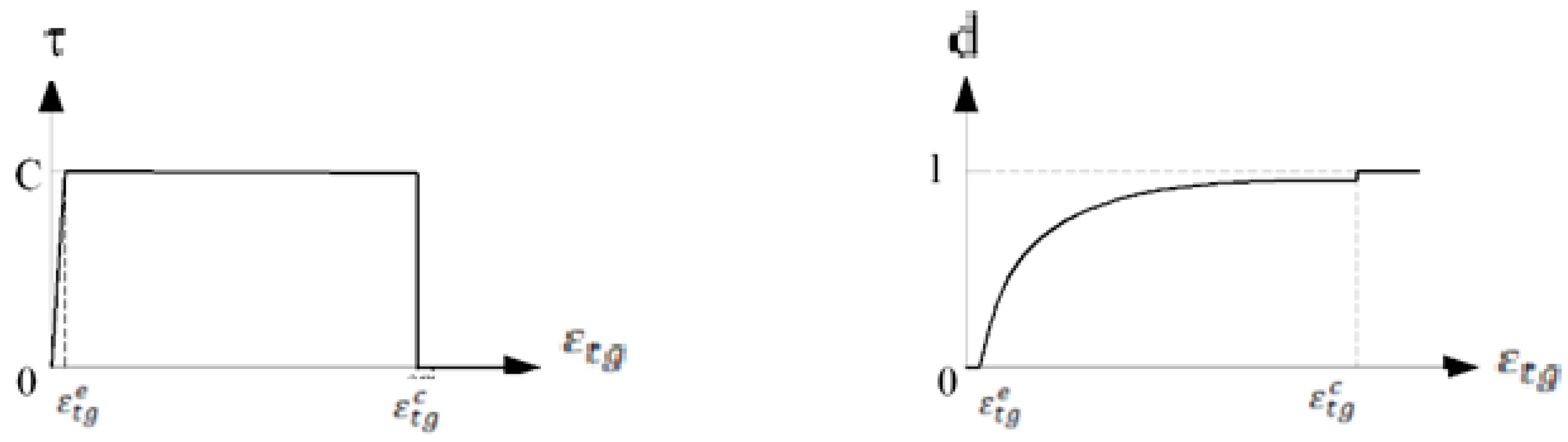
- To simulate local failure at the steel–concrete interface when shear-induced cracking leads to a loss of adhesion.
- To represent sliding between the concrete and the rebar prior to complete interface failure.
- To account for local friction between concrete and steel following interface failure.
- A single layer of volume elements is used to represent the bond zone between the two materials.
- Two types of mechanical behavior are considered for these elements: one corresponding to macrocrack propagation (Mode I) through the rebar, and the other to the bond behavior (shear response) at the interface.
- Each volume element is assigned to only one type of behavior. That is, a given element either simulates the propagation of a macrocrack through the rebar or models the bonding behavior between concrete and steel.
- If only one of the two failure criteria is satisfied within the element, it will be assigned accordingly—as either a tension or shear element—for the remainder of the simulation.
- If both criteria are satisfied, the element will follow the mode (tension or shear) associated with the greater margin between the applied stress (tensile or shear) and its corresponding strength (ft or C), and this behavior will remain fixed throughout the simulation.
3. Determination of the Mechanical Parameter Values Related to the Shear Behavior of the Bond Elements
- Experimental data available: Experimental results from tie-beam tests involving the same concrete and reinforcement in the structure being analyzed are available. This is the ideal case as it allows for direct calibration.
- No experimental data available: In the absence of physical test results, the inverse method can still be performed using numerical tie-beam simulations. In this case, validated local modeling is employed to replicate the test virtually, using the following approach:
- ○
- The rebar is modeled with its actual ribbed geometry.
- ○
- The cracking process in the surrounding concrete is simulated using the probabilistic semi-explicit cracking model (see Section 2). A highly refined mesh is applied around the rebar—at the scale of the ribs—to capture the detailed cracking, sliding, and friction behavior. This numerical technique has already proven successful in prior studies [25].
- The macroscopic behavior of the tie-beam—particularly the load–displacement curve (i.e., the relative displacement between the rebar and concrete at one end)—is not sufficient by itself to identify a unique set of values for the maximum shear stress (C) and the tangential critical strain (εtgc). Additional criteria, such as the number of macrocracks observed in the numerical simulation, must also be considered to refine the calibration.
- The identified values of C and εtgc are dependent on the size of the volume elements. Therefore, it is essential to use the same element size in the simulation of the reinforced concrete structure as was used in the inverse identification process.
4. PSEC Model and Concrete/Steel Bond Model in Dynamics
5. Conclusions and Perspective
Funding
Data Availability Statement
Conflicts of Interest
References
- Sharabi, M.N. Numerical modeling of reinforced concrete bond. Nucl. Eng. Des. 1986, 91, 207–216. [Google Scholar] [CrossRef]
- Désir, M.; Romdhane, M.R.B.; Ulm, F.-J.; Fairbairn, E.M.R. Steel–concrete interface: Revisiting constitutive and numerical modeling. Comput. Struct. 1999, 71, 489–503. [Google Scholar] [CrossRef]
- Cox, J.V.; Guo, J. Implementation of a plasticity bond model for reinforced concrete. Comput. Struct. 2000, 77, 65–82. [Google Scholar]
- Willam, K.; Rhee, I.; Shing, B. Interface damage model for thermomechanical degradation of heterogeneous materials. Comput. Fail. Mech. 2004, 30–32, 3327–3350. [Google Scholar] [CrossRef]
- Lowes, L.N.; Moehle, J.P.; Goxindjee, S. Concrete-steel bond model for using in finite element modeling of reinforced concrete structures. ACI Struct. J. 2004, 101, 501–511. [Google Scholar]
- Ragueneau, F.; Dominguez, N.; Ibrahimbegovic, A. Thermodynamics-based interface model for cohesive brittle materials: Application to bond slip in RC structures. Comput. Methods Appl. Mech. Engrg. 2006, 195, 7249–7263. [Google Scholar] [CrossRef]
- Brisotto Dde, S.; Bittencourt, E.; d’ ABesse, V.M.R. Simulating bond failure in reinforced concrete by a plastic model. Comput. Struct. 2012, 106–107, 81–90. [Google Scholar] [CrossRef]
- Filho, F.M.A.; El Debs, M.K.; El Debs, A.L.H.C. Numerical approach of the bond stress behavior of steel bars embedded in self-compacting concrete and in ordinary concrete using beam models. Rev. IBRACOM Estru. Mater. 2013, 6, 499–512. [Google Scholar] [CrossRef]
- Jason, L.; Torre-Casanova, A.; Davenne, L.; Pinelli, X. Cracking behavior of reinforced concrete beams: Experiment and simulations on the numerical influence of the steel-concrete bond. Int. J. Fract. 2013, 180, 243–260. [Google Scholar] [CrossRef]
- CMeaud, B.; Jurkiewiez, E. Ferrier, Steel–concrete bonding connection: An experimental study and non-linear finite element analysis. Int. J. Adhes. Adhes. 2014, 54, 131–142. [Google Scholar]
- Miranda, M.P.; Morsch, I.B.; de Brisotto, D.S.; Bittencourt, E.; Carvalho, E.P. Steel-concrete bond behavior: An experimental and numerical study. Constr. Build. Mater. 2021, 271, 121918. [Google Scholar] [CrossRef]
- Liu, H.; Chen, W.; Guo, R.; Liao, W.; Du, X. Theoretical and numerical study on the bond behavior between reinforcing steel and concrete. J. Build. Eng. 2024, 90, 109398. [Google Scholar] [CrossRef]
- Rossi, P.; Wu, X. Probabilistic model for material behavior analysis and appraisement of concrete structures. Mag. Concr. Res. 1992, 44, 271–280. [Google Scholar] [CrossRef]
- Rossi, P. Basis of A New Numerical Model of the Concrete/Steel Bond in Reinforced Concrete Structures. Cem. Based Compos. 2023, 1, 5839. [Google Scholar] [CrossRef]
- Rita, M. Implementation of a Macroscopic Probabilistic Model of Cracking Concrete Using Parallelization Strategies. Ph.D. Dissertation, Universidade Federal do Rio de Janeiro, Rio de Janeiro, Brazil, 2022. [Google Scholar]
- Rita, M.; Rossi, P.; Fairbairn, E.; Ribeiro, F. Determination of the Probabilistic Properties of the Critical Fracture Energy of Concrete Integrating Scale Effect Aspects. Appl. Sci. 2024, 14, 462. [Google Scholar] [CrossRef]
- Lemaitre, J.; Chaboche, J.-L. Mechanics of Solid Materials; University of Cambridge: Cambridge, UK, 1990. [Google Scholar]
- Fichant, S.; La Borderie, C.; Pijaudier-Cabot, G. Isotropic and anisotropic descriptions of damage in concrete structures, isotropic and anisotropic descriptions of damage in concrete structures. Mech. Cohesive-Frict. Mater. 1999, 4, 339–359. [Google Scholar] [CrossRef]
- Jirasek, M. Modeling of localized damage and fracture in quasi-brittle materials. In Continuous and Discontinuous Modelling of Cohesive-Frictional Materials; Springer: Berlin/Heidelberg, Germany, 2001; pp. 17–29. [Google Scholar]
- Jirasek, M. Non-local damage mechanics with application to concrete. Rev. Française Génie Civ. 2004, 8, 683–707. [Google Scholar] [CrossRef]
- Zhang, W.; Cai, Y. Basis of Isotropic Damage Mechanics. In Continuum Damage Mechanics and Numerical Applications, Advanced Topics in Science and Technology in China; Springer: Berlin/Heidelberg, Germany, 2010. [Google Scholar]
- Rots, J.; Nauta, P.; Kuster, G.; Blaauwendraad, J. Smeared crack approach and fracture localization in concrete. Heron 1985, 30, 48. [Google Scholar]
- Jirasek, M.; Zimmermann, T. Rotating crack model with transition to scalar damage. J. Eng. Mecchanics 1998, 124, 277–284. [Google Scholar] [CrossRef]
- Irwin, G. Linear fracture mechanics, fracture transition, and fracture control. Eng. Fract. Mech. 1968, 1, 241–257. [Google Scholar] [CrossRef]
- Phan, T.S.; Rossi, P.; Tailhan, J.-L. Numerical modeling of the concrete/rebar bond in a reinforced concrete structural element: A multi-scale approach. In Cement and Concrete Composites; 2015; pp. 1–9. [Google Scholar] [CrossRef]
- Costa, G.; Rossi, P.; Rita, M.; Fairbairn, E.; Ribeiro, F. Use of a Semi-Explicit Probabilistic Numerical Model for Concrete Cracking: From Static to Dynamics Loadings. Appl. Sci. 2024, 14, 10643. [Google Scholar] [CrossRef]
- Rossi, P. A physical phenomenon which can explain the mechanical behaviour of concrete under high strain rates. Mater. Struct. 1991, 24, 422–424. [Google Scholar] [CrossRef]
- Ozbolt, J.; Sharma, A.; Reinhardt, H.-W. Dynamics fracture of concrete–compact tension specimen. Int. J. Solids Struct. 2011, 48, 1534–1543. [Google Scholar] [CrossRef]
- Cusatis, G. Strain-rate effects on concrete behavior. Int. J. Impact Eng. 2011, 38, 162–170. [Google Scholar] [CrossRef]
- Ozbolt, J.; Riedel, W. Modelling the response of concrete structures from strain rate effects to shock induced loading. In Understanding the Tensile Properties of Concrete; Elsevier: Amsterdam, The Netherlands, 2013; pp. 295–340. [Google Scholar]
- Ozbolt, J.; Bosnjak, J.; Sola, E. Dynamic fracture of concrete compact tension specimen: Experimental and numerical study. Int. J. Solids Struct. 2013, 50, 4270–4278. [Google Scholar] [CrossRef]
- Ozbolt, J.; Bede, N.; Sharma, A.; Mayer, U. Dynamic fracture of concrete l-specimen: Experimental and numerical study. Eng. Fract. Mech. 2015, 148, 27–41. [Google Scholar] [CrossRef]
- Lee, S.; Kim, K.-M.; Park, J.; Cho, J.-Y. Pure rate effect on the concrete compressive strength in the split hopkinson pressure bar test. Int. J. Impact Eng. 2018, 113, 191–202. [Google Scholar] [CrossRef]
- Peng, Y.; Wang, Q.; Ying, L.; Kamel, M.M.; Peng, H. Numerical simulation of dynamic mechanical properties of concrete under uniaxial compression. Materials 2019, 12, 643. [Google Scholar] [CrossRef]

Disclaimer/Publisher’s Note: The statements, opinions and data contained in all publications are solely those of the individual author(s) and contributor(s) and not of MDPI and/or the editor(s). MDPI and/or the editor(s) disclaim responsibility for any injury to people or property resulting from any ideas, methods, instructions or products referred to in the content. |
© 2025 by the author. Licensee MDPI, Basel, Switzerland. This article is an open access article distributed under the terms and conditions of the Creative Commons Attribution (CC BY) license (https://creativecommons.org/licenses/by/4.0/).
Share and Cite
Rossi, P. Concrete/Steel Bond in Reinforced Concrete Structures Subjected to Dynamic Loadings: Basis of New Numerical Model. Constr. Mater. 2025, 5, 32. https://doi.org/10.3390/constrmater5020032
Rossi P. Concrete/Steel Bond in Reinforced Concrete Structures Subjected to Dynamic Loadings: Basis of New Numerical Model. Construction Materials. 2025; 5(2):32. https://doi.org/10.3390/constrmater5020032
Chicago/Turabian StyleRossi, Pierre. 2025. "Concrete/Steel Bond in Reinforced Concrete Structures Subjected to Dynamic Loadings: Basis of New Numerical Model" Construction Materials 5, no. 2: 32. https://doi.org/10.3390/constrmater5020032
APA StyleRossi, P. (2025). Concrete/Steel Bond in Reinforced Concrete Structures Subjected to Dynamic Loadings: Basis of New Numerical Model. Construction Materials, 5(2), 32. https://doi.org/10.3390/constrmater5020032