Article

Corrosion Effects on Bond Degradation and Cracking Patterns in Lapped Spliced Joints of Reinforced Concrete

by
Amged O. Abdelatif
1,*,
Sara E. Onsa
1,
Aya E. Ahmed
1,†,
Eiman A. Abdelraouf
1,†,
Razan M. Abdalgader
1,†,
Mohamed I. Ibrahim
1,† and
Joško Ožbolt
2
1
Civil Engineering Department, Faculty of Engineering, University of Khartoum, Khartoum P.O. Box 321, Sudan
2
Institute of Construction Materials, University of Stuttgart, 70569 Stuttgart, Germany
*
Author to whom correspondence should be addressed.
These authors contributed equally to this work.
Constr. Mater. 2025, 5(1), 8; https://doi.org/10.3390/constrmater5010008
Submission received: 20 December 2024 / Revised: 22 January 2025 / Accepted: 23 January 2025 / Published: 2 February 2025

Abstract

:
This research study aims to enhance the understanding of corrosion behaviour in lapped spliced joints within reinforced concrete structures. Specifically, the effect of corrosion on bond degradation and crack formation is investigated. Accelerated corrosion tests were conducted on two sets of semi-cylindrical samples and half-beam blocks. By applying a constant voltage, the current-time relationship during the corrosion process was obtained. Subsequently, the samples were subjected to pull-out testing to assess their bond strength. Three primary modes of bond failure were observed: pull-out, splitting, or a combination of both. Notably, the results demonstrate that the reduction in bond strength is directly related to the corrosion level, considering factors such as mass loss, section loss, and diameter reduction. Furthermore, a strong correlation exists between corrosion-induced cracks and the weakening of bond strength. These findings align with existing research and enrich the experimental data in the current corrosion database for lap splice joints in reinforced concrete structures.

1. Introduction

The corrosion of reinforcing steel is a significant factor contributing to the deterioration of reinforced concrete structures. This corrosion leads to an unexpected reduction in serviceability, often occurring earlier than anticipated [1]. The corrosive process reduces the cross-sectional area and the load-bearing capacity of reinforcing steel bars, thereby weakening the structural integrity of the construction [2,3]. When steel corrodes, the resulting corrosion products occupy a larger volume than the original steel. This volumetric expansion exerts tensile stresses on the surrounding concrete, potentially causing cracking and spalling of the concrete cover. Consequently, this can lead to a loss of structural bond between the reinforcement and concrete [4,5,6,7,8,9,10]. In the early stages of corrosion, the increase in the rebar’s cross-sectional area can enhance the frictional component of the bond between steel and concrete. However, as corrosion progresses, it can lead to the development of longitudinal cracking, which in turn reduces bond strength [4]. As corrosion continues, the height of the rebar’s ribs decreases, and the formation of corrosion products leads to disengagement between the ribs and concrete, reducing the effective bearing area of the rib [4].
While extensive research has investigated corrosion in reinforced concrete (RC) structures, particularly concerning single and multiple rebars, a notable gap exists in the literature regarding the specific impact of corrosion at lapped splice joints [11,12,13]. This is despite the prevalence of lap splices as a common connection method in RC construction and their susceptibility to bond degradation when exposed to corrosive environments [12,13,14,15,16,17,18,19]. Existing studies on corrosion at lapped splice joints demonstrate that corrosion significantly reduces the cross-sectional area of steel reinforcement, leading to a decrease in load-carrying capacity and a deterioration of the bond between the steel and concrete [12,13,14,17,19]. This bond degradation manifests as concrete cracking and spalling due to the expansive forces of corrosion products, leading to a transition from ductile to brittle failure modes [11,13,20]. Furthermore, research indicates a considerable reduction in bond strength at lap splices due to corrosion, with a 2.5% corrosion level causing a reduction between 15% and 25% and a small percentage of diameter loss in reinforcement causing an 80% reduction in bond [11]. The concrete cover-to-bar diameter ratio also influences bond degradation, and while transverse reinforcement such as stirrups can improve bond strength, its effectiveness can decrease with increased concrete cover [12,18,21]. The electrochemical nature of corrosion results in rust formation, which further deteriorates the bond and the presence of short lap splices exacerbates this by not allowing stresses in longitudinal bars to reach the yield strength [17,22]. Moreover, the combination of corrosion and fatigue loading can considerably diminish the fatigue life of lap-spliced joints [18]. While some studies have examined the structural capacity of RC elements, there is a need for further research that focuses on the non-mechanical behavior and mechanics of bond degradation due to corrosion [11,13].
Therefore, this study aimed to experimentally assess the corrosion at lap splice joints and its consequences, particularly the crack pattern and degradation of bond strength. This research contributes valuable data for validating numerical models, ultimately enhancing the durability and safety of RC structures in corrosive environments [19,23]. Unique contributions include experimental data on the current-time relationship during corrosion, modes of bond failure, the correlation between corrosion-induced cracks and bond strength reduction, and a newly experimental setup for testing bond degradation in lapped splice joints, enriching the experimental database for lap splice joints in RC structures.

2. Experimental Methodology

This study employed an experimental approach to investigate the effects of corrosion on lapped splice joints in reinforced concrete (RC) structures, focusing on crack patterns and bond degradation. An accelerated corrosion technique, using an impressed voltage, was implemented to simulate corrosive conditions. This method is popular and widely accepted by researchers for simulating corrosion in concrete [3,24].

2.1. Materials

Controlled concrete mix, targeting a compressive strength of 25 MPa, was prepared using a water-cement ratio of 0.63. The mix design comprised 1089 kg/m³ coarse aggregate, 703 kg/m³ fine aggregate, and 258 kg/m³ Ordinary Portland Cement (OPC). Sodium chloride (NaCl) was incorporated into the mix at a concentration equivalent to 10% of the cement weight (25.8 kg/m³), to facilitate the acceleration of the corrosion process [23]. Reinforcing steel bars Gr. 460 with diameters of 12 mm, 16 mm, 20 mm, and 25 mm were utilized.

2.2. Specimen Preparation

Two distinct types of specimens were fabricated for this study: half-beam block samples and semi-cylinder samples (Table 1). The designation “K” stands for blocks and “C” stands for cylinders, followed by the rebar diameter and then the concrete cover. For example, “K-12-20” indicates a block specimen with a 12 mm diameter rebar and a 20 mm concrete cover, while “C-16-30” indicates a cylinder specimen with a 16 mm diameter rebar and a 30 mm concrete cover. All specimens were tested after a minimum curing period of 28 days, Table 1.

2.2.1. Block Samples

Based on literature [11,13], two variations, designated K-16-20 and K-20-30 (Figure 1), were cast with different reinforcing bar diameters (16 mm and 20 mm) and therefore different c/d ratios. These 200 × 200 × 150 mm blocks, as shown in Figure 1, simulated real-world conditions with lapped rebar at the bottom corners.

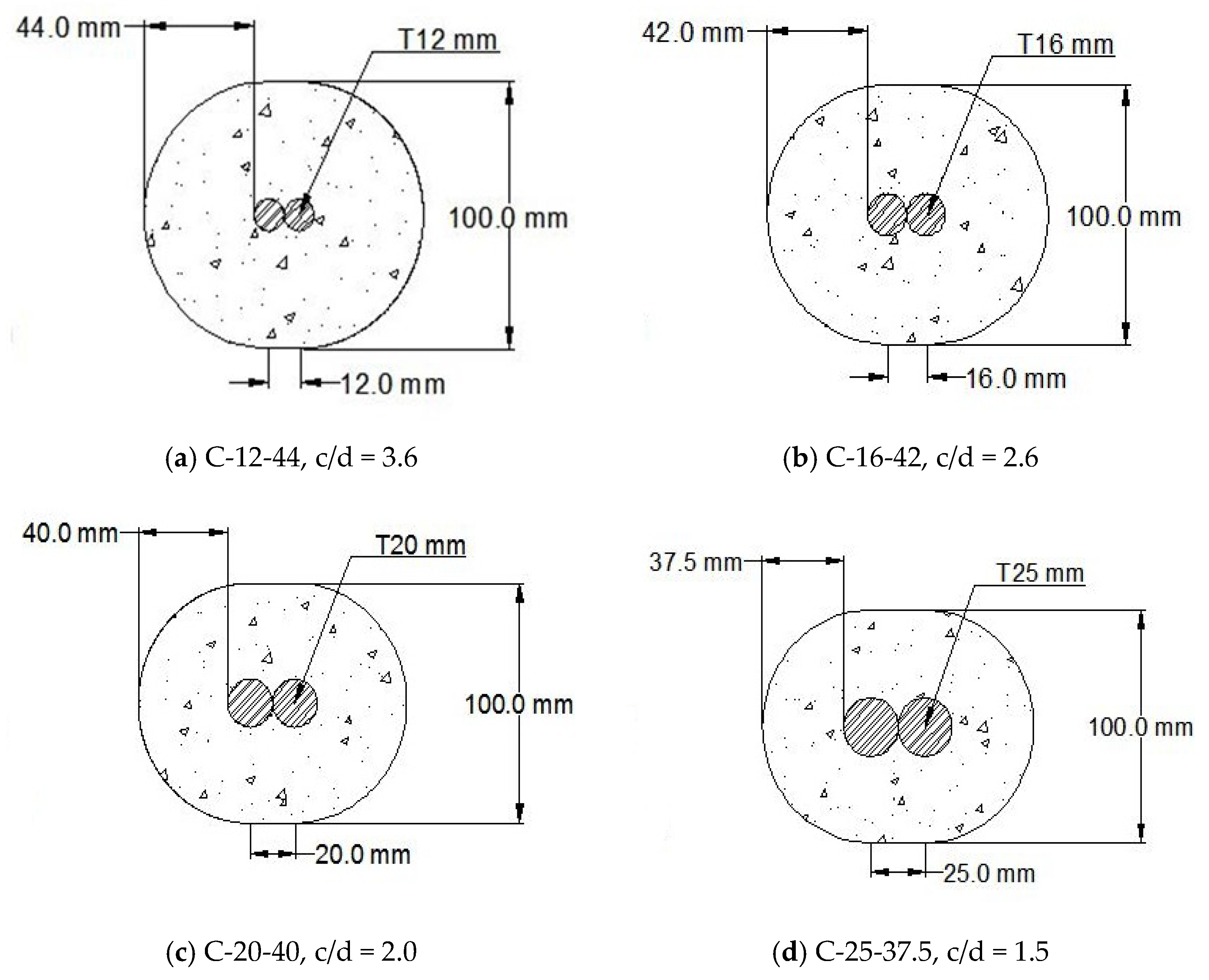
2.2.2. Semi-Cylinder Samples

Four variations, designated C-12-44, C-16-42, C-20-40, and C-25-37.5 (Figure 2), were cast with varying concrete cover-to-rebar diameter (c/d) ratios. The semi-cylinder samples were designed to provide a uniform concrete cover. Moulds were formed by separating two halves of a cylinder by a distance equivalent to the diameter of the steel rebar. Each 200 mm long semi-cylinder contained two centrally placed steel reinforcing bars with a 200 mm lap length. For the purposes of assessing bond degradation, samples type C-12-44 with a 110 mm lap length were prepared into two Groups A and B, with extended parts of steel rebar to facilitate gripping in the pull-out machine.

2.3. Accelerated Corrosion Test

A 12-volt DC power supply is used to accelerate the electrochemical reactions that cause steel corrosion using the impressed voltage technique [23], while a 10% NaCl solution is used as an aggressive electrolyte to speed up the depassivation of steel by increasing the concentration of chloride ions [19]. These values are chosen for their practicality and ability to induce relatively quick and measurable corrosion, even though they may not fully represent natural corrosion conditions [14,25,26,27].
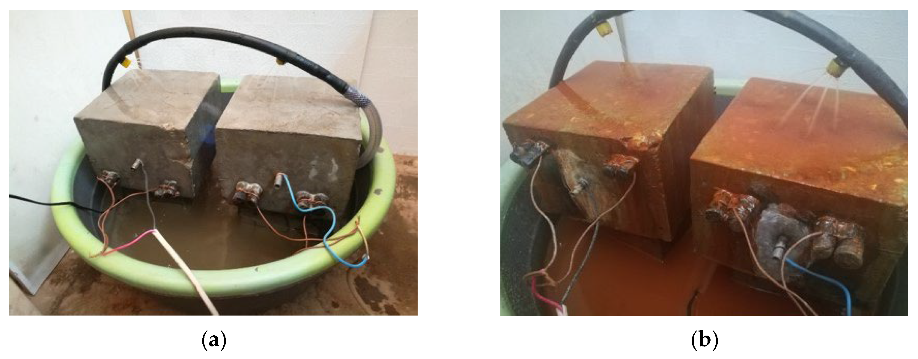
  • Half-Beam Block Samples: For the half-beam block samples, the electrolyte was delivered through a hose and sprinkled onto the block surfaces (Figure 3). A centrally located stainless-steel tube acted as the cathode.
  • Semi-Cylinder Samples: The semi-cylinder samples were immersed in the electrolyte for the crack pattern test (Figure 4a), while the samples used for the bond pull-out test employed the sprinkling method due to the extension of the steel rebar on both sides for the sake of gripping in the pull-out machine. A stainless-steel mesh was wrapped around the sample surface to serve as the cathode (Figure 4b).
It is worth mentioning that sprinkling water on the concrete was found to be more effective in expediting the test, as it facilitated better penetration of both water and oxygen.

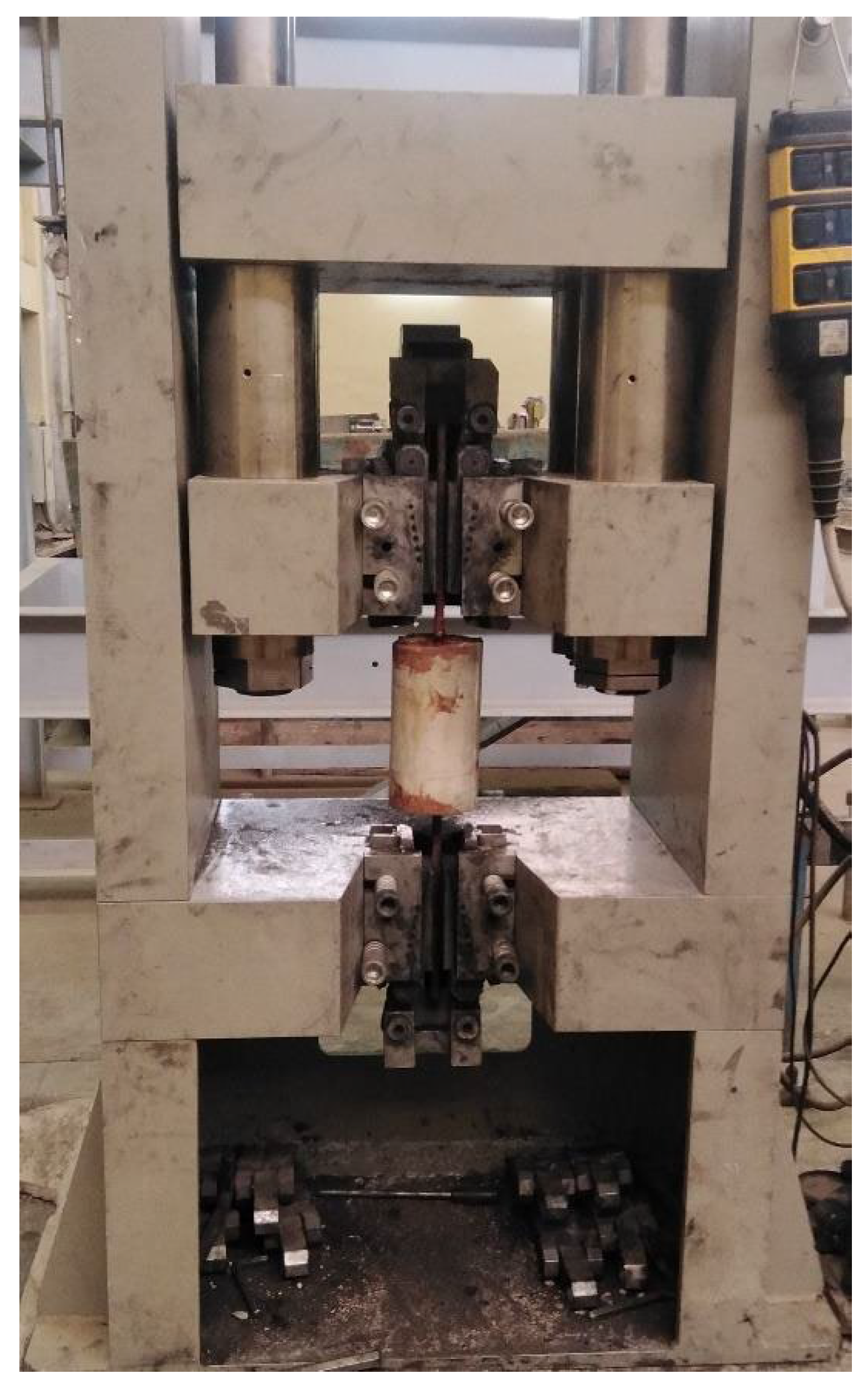
2.4. Bond Degradation Test (Pull-Out Test)

Pull-out tests are commonly used to assess the bond between reinforcing steel and concrete [28,29,30]. These tests involve embedding a steel rebar in a concrete block and applying a tensile force to pull the bar out, while measuring the force and slip [31]. Pull-out tests are popular due to their simplicity and ease with which parameters like concrete cover, bar diameter, and development length can be altered [16]. These tests provide valuable data about the bond-slip relationship and how corrosion affects it [16,17,32,33]. In this study, the pull-out tests were performed exclusively on the semi-cylinder type C-12-44 specimens using two distinct groups of samples. The first group, referred to as Group A, consisted of four samples. However, due to the unforeseen circumstances of the COVID-19 lockdown, the samples were unintentionally left for a period of five months before testing. This extended period offered new insights into the long-term effects of corrosion on the samples. Consequently, a new set of five samples, referred to as Group B, was cast for testing.
The test samples were then subjected to an accelerated corrosion for durations of 8, 12, 16, 18, 24, 48, 72, and 100 h before pull-out test (refer to Table 2). The current in the corrosion cell was acquired at regular intervals, and time-current curves were extracted to represent different corrosion levels.
The bond degradation was assessed using a pull-out test. Each sample was positioned on the universal tensile machine, manufactured by Controls Group (as illustrated in Figure 5), which facilitated the pulling out of the spliced bars from one another. The test was conducted under a constant tensile stress rate of 2 N/mm², and load-slip readings were meticulously recorded for each sample. This data was then used to establish the bond-slip relationships. This rigorous methodology ensured the accuracy and reliability of the results obtained in this study.

3. Results and Discussions

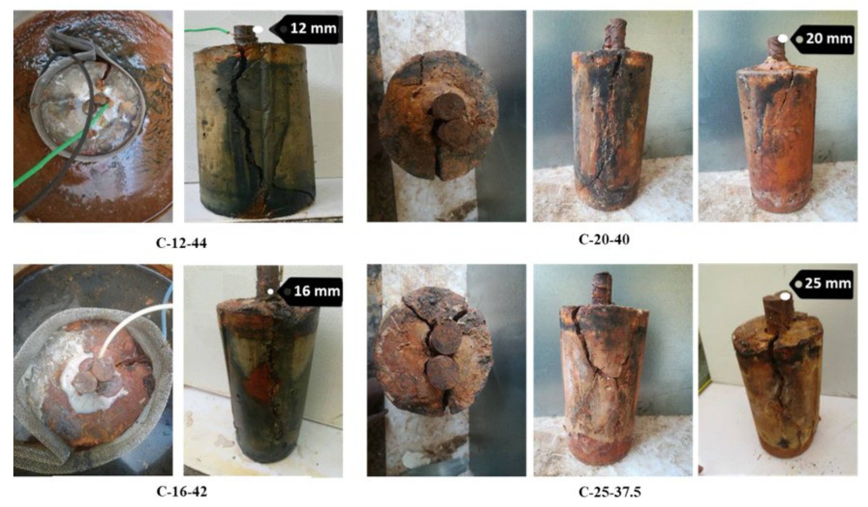
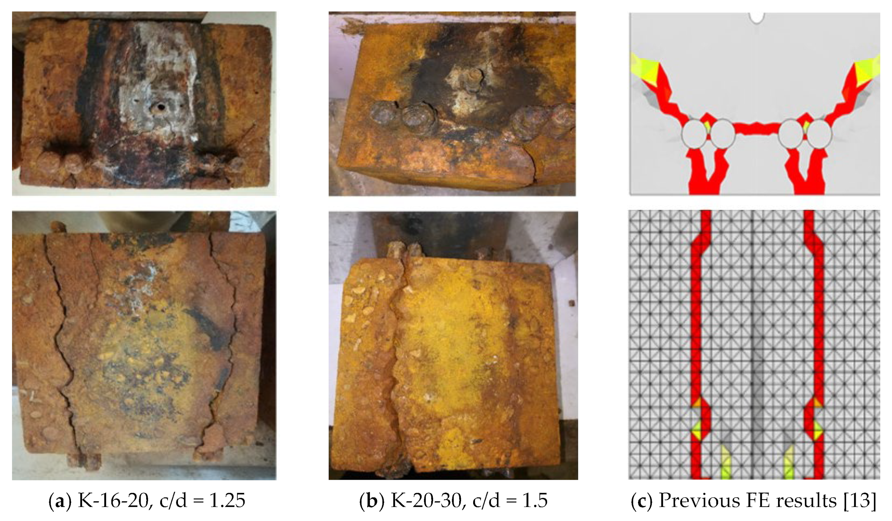
3.1. Crack Pattern at Lap Splice Joints

The initial appearance of cracks was observed after 3, 9, 21, and 16 days for the samples C-12-44, C-16-42, C-20-40, and C-25-37.5, respectively. Notably, samples with a smaller cover to diameter (c/d) ratio required a longer duration to exhibit cracking, excluding the final semi-cylinder.
In all instances, the initiation of cracks was at the top surface of the concrete cylinder, subsequently propagating parallel to the steel bars, as depicted in Figure 6. The formation of longitudinal cracks was prominent along the short face (i.e., the left and right face in Figure 2). This can be attributed to the higher accumulation of rust products along the top and bottom surfaces (refer to Figure 2) compared to the sides. This accumulation exerts pressure at the interface between the steel and concrete [8], leading to the formation of longitudinal cracks. As the rust products increase, the pressure on the sides may induce additional cracks on the top surface, as observed in the C-25-37.5 sample. Generally, samples with a smaller cover (lower c/d ratio) exhibited more severe cracking compared to other samples, supporting previous findings that the severity of cracks is dependent on the concrete cover [4].
In the case of block samples, the cracks were longitudinal, running parallel to the steel bars. Over time, these cracks widened, and additional cracks emerged between the bars and around the stainless-steel tube (see Figure 7). The crack pattern in this sample, characterized as face splitting, bears similarity to those reported in previous tests on full-scale beams with lap splice joints [34] and closely aligns with numerical results from existing literature [13].
The experiment was halted after 544 h of voltage application. The onset of cracking was noted after 370 h and 315 h for the samples K-16-20 and K-20-30, respectively. A significant advantage of the block sample is the visibility of the crack between steel bars (i.e., in the cross-section), a feature not possible with full-scale beams.

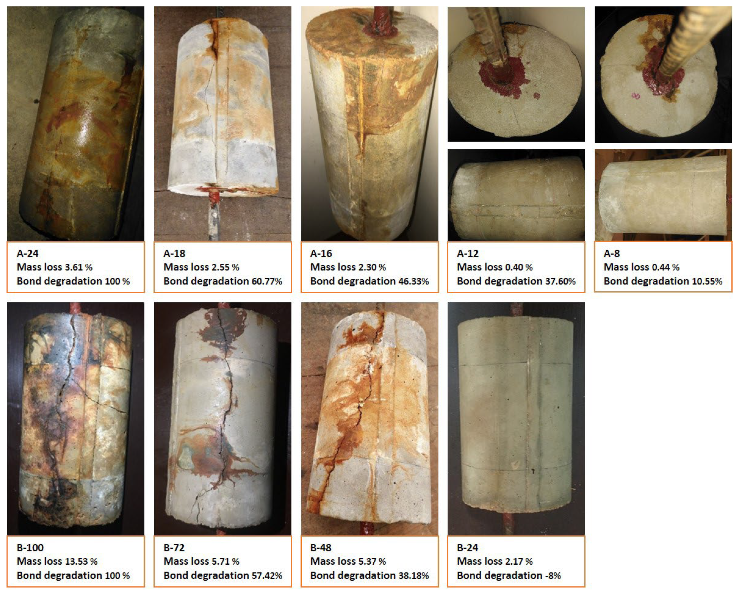
3.2. Bond Degradation at Lap Splice Joints

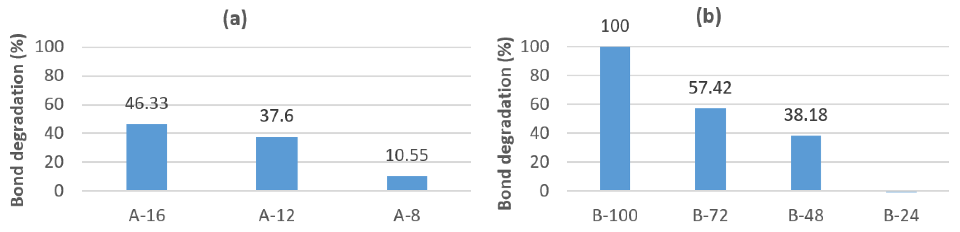
3.2.1. Accelerated Corrosion Test Results

The time-current relationship for both Group (A) and Group (B) of samples, designated as C-12-44, is depicted in Figure 8. As the corrosion process initiates, the corrosion products gradually infiltrate the concrete pores, leading to a decrease in current values due to an increase in resistivity. Subsequently, the resistivity diminishes further as cracks form—a consequence of the volumetric expansion of corrosion products. As these cracks widen, the current values begin to rise.
The experimental results were analysed using Faraday’s Law [28], expressed by Equations (1)–(3).
m = Q w a n F
C t = m m i × 100
i c o r r = Q T A
where:
m = mass loss (in grams) of corroded reinforcement
m i = mass of original metal
Q = the total charge passed, calculated by getting the area under the curve of current-time relationship
w a = atomic molar mass (55.847 g/mol for Fe)
n = number of electrons transferred per iron atom = 2
F = Faraday’s constant (96,487 C/mol)
Ct = The percentage of mass loss of the corroded reinforcement
T = Total time duration
A = original area of the bar
i c o r r = corrosion current density which is the ratio between the original surface area of steel bar to the average current, it is measured in (A/cm2).
In Table 3, calculations for mass loss, section loss, and the reduction in bar diameter due to corrosion are presented, assuming uniform corrosion (with a steel density of 0.008 gm/mm³). Importantly, the applied corrosion current density falls within the ranges reported in the existing literature [35]. Additionally, Figure 9 illustrates the percentage of mass loss attributed to corrosion at different time intervals for both Group A and Group B.

3.2.2. Pull-Out Test Results

The bond-slip relationships for both groups, as derived from the pull-out test, are depicted in Figure 10. This illustration reveals a rapid degradation of bond strength in Group A compared to Group B, which was subjected to natural corrosion for an period exceeding five months.
For instance, the B-24 sample exhibits a marginally superior bond strength than the control semi-cylinder B-0, registering at 108%. This increase can be attributed to the enhancement of bond strength by the early corrosion product [4].
The failure mode of the bond in the semi-cylinders was determined to be either a pull-out, splitting, or a combination of both, as shown in Figure 11. Table 4 and Figure 12 provides a summary of the bond strength degradation in each group of lapped splice joint semi-cylinders. It is of important to note that both semi-cylinders A-24 and B-100 experienced failure due to severe corrosion cracking prior to the execution of the pull-out test. This observation underscores the detrimental impact of prolonged corrosion on the structural integrity.

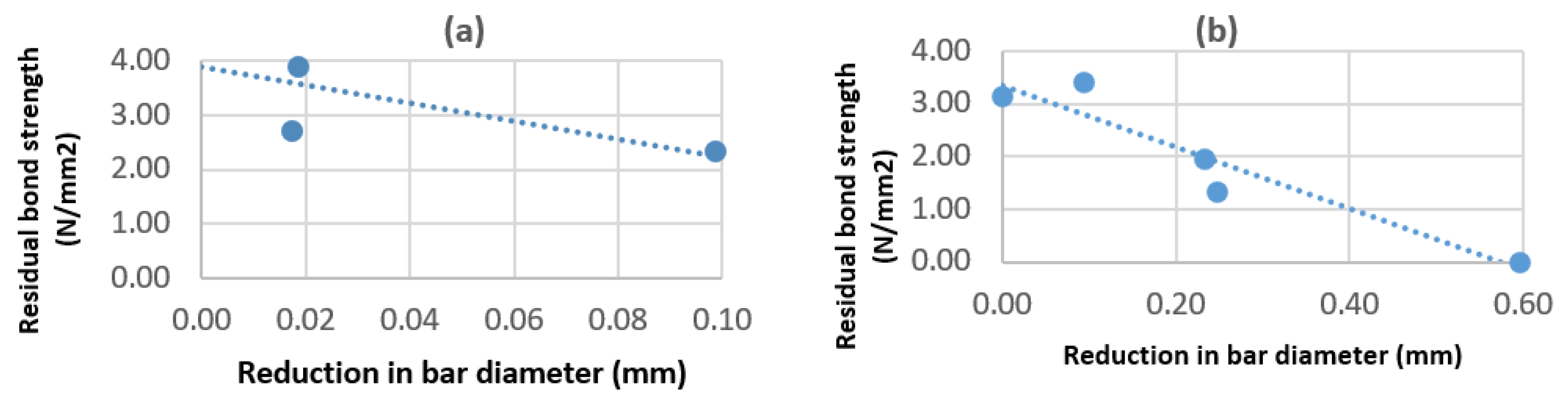
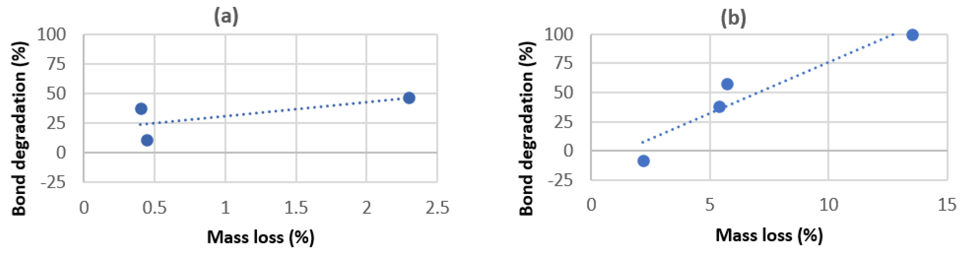
3.2.3. Correlation Between Bond Reduction and Bar Diameter, Mass Loss, and Corrosion Cracks

The evaluation of residual bond strength is initially conducted in relation to the reduction in bar diameter, Figure 13. The figures indicate a direct proportionality between the reduction in bond strength and the reduction in bar diameter which also corresponds to section loss.
Subsequently, in Figure 14, a comparative analysis of bond strength across different samples is presented, considering their mass loss. As anticipated, the bond strength exhibits a reduction corresponding to an increase in mass loss, indicative of the corrosion level. The reduction factor was found to adhere to the format 1 α C t , which is consistent with previous literature [20]. In this study, the value of α was ranging from 22 for Group-A to 7.5 for Group-B, as compared to an empirical value of 10 reported by Shihata [20]. The discrepancy in these findings can be attributed to the differences in the experimental conditions between the experiments.
Lastly, the examination of test samples reveals a correlation between corrosion cracks (observed just prior to the pull-out testing), mass loss, and bond degradation, as depicted in Figure 15. It is evident that the severity of cracks is directly associated with the reduction in bond capacity between steel and concrete, as would be expected. This underscores the critical role of corrosion in compromising the bond integrity within the steel-concrete interface.

4. Conclusions

This study presents a comprehensive experimental evaluation of corrosion at lap splice joints in concrete structures using a novel testing setup for semi-cylinders and half-beam blocks with lapped reinforcement. The samples underwent accelerated corrosion tests to analyze crack patterns and bond degradation over time.
The crack patterns observed in block samples are consistent with those reported in existing experimental and numerical studies. In semi-cylinder samples, cracks initiated from the center and propagated toward the short surface.
Bond degradation was assessed through pull-out tests on two groups of semi-cylinder samples subjected to different levels of corrosion. The results highlight the time-current and bond-slip relationships for the samples, alongside the corresponding bond strength degradation. A significant correlation was found between bond degradation and factors such as mass loss, reduction in bar diameter, and corrosion-induced cracks. The predominant modes of bond failure were pull-out, splitting, or a combination of both.
This research significantly enriches the experimental database on corrosion at lap splice joints in concrete. The findings are valuable for validating advanced numerical models and may inspire further numerical and experimental studies in this field. Additionally, such studies could result in a deep understanding that leads to practical recommendations for enhancing the durability of concrete structures.

Author Contributions

Experimental design, methodology, supervision, writing the final draft, A.O.A.; Writing and conducting the experiments on the crack pattern on block samples, S.E.O.; writing and conducting the experiments on the crack pattern on semi-cylinders samples in addition to the bond degradation on both semi-cylinders and blocks samples, A.E.A., E.A.A., R.M.A. and M.I.I.; Conceptualization, reviewing and editing, J.O. All authors have read and agreed to the published version of the manuscript.

Funding

This research received no external funding.

Data Availability Statement

The original contributions presented in the study are included in the article, further inquiries can be directed to the corresponding author.

Conflicts of Interest

The authors declare no conflicts of interest.

References

  1. Broomfield, J.P. Corrosion of Steel in Concrete: Understanding, Investigation and Repair; CRC Press: Boca Raton, FL, USA, 2023. [Google Scholar]
  2. Du, Y.G.; Chan, A.H.C. Residual capacity of corroded reinforcing bars. Mag. Concr. Res. 2005, 57, 13. [Google Scholar] [CrossRef]
  3. FIB. Bond of Reinforcement in Concrete: State-of-Art Report; International Federation for Structural Concrete: Lausanne, Switzerland, 2000. [Google Scholar]
  4. Capozucca, R. Damage to Reinforced Concrete Due to Reinforcement Corrosion. Constr. Build. Mater. 1995, 9, 295–303. [Google Scholar] [CrossRef]
  5. Mancini, G.; Tondolo, F. Effect of bond degradation due to corrosion—A literature survey. Struct. Concr. 2014, 15, 408–418. [Google Scholar] [CrossRef]
  6. Pan, T. Continuous damage of concrete structures due to reinforcement corrosion: A micromechanical and multi-physics based analysis. J. Build. Eng. 2024, 95, 110139. [Google Scholar] [CrossRef]
  7. Szweda, Z.; Skórkowski, A.; Konečný, P. The Influence of Corrosion Processes on the Degradation of Concrete Cover. Materials 2024, 17, 1398. [Google Scholar] [CrossRef]
  8. Abdelatif, A.O.; Ožbolt, J. Omara A Stress distribution in thick-walled cylinder due to non-uniform radial pressure on the example of reinforcement corrosion in concrete. Mater. Corros. 2020, 71, 1660–1666. [Google Scholar] [CrossRef]
  9. Almusallam, A.A. Effect of degree of corrosion on the properties of reinforcing steel bars. Constr. Build. Mater. 2001, 15, 361–368. [Google Scholar] [CrossRef]
  10. Almusallam, A.A.; Al-Gahtani, A.S.; Aziz, A.R.; Rasheeduzzafar. Effect of reinforcement corrosion on bond strength. Constr. Build. Mater. 1996, 10, 123–129. [Google Scholar] [CrossRef]
  11. Shihata, A. Corroded tension lap-spliced rc beams with frp wraps. In Proceedings of the 6th International Conference on FRP Composites in Civil Engineering, Rome, Italy, 13–15 June 2012. [Google Scholar]
  12. Moodi, Y.; Sohrabi, M.R.; Mousavi, S.R. Effects of stirrups in spliced region on the bond strength of corroded splices in reinforced concrete (RC) beams. Constr. Build. Mater. 2020, 230, 116873. [Google Scholar] [CrossRef]
  13. Abdelatif, A.O.; Ožbolt, J.; Gambarelli, S. 3D finite element modelling of corrosion of lap splice joints in concrete. Constr. Build. Mater. 2018, 169, 124–131. [Google Scholar] [CrossRef]
  14. Mahlawe, A.E. Effect of Corrosion of Lap-Spliced Steel Reinforcement on the Flexural Strength of Reinforced Concrete Beams. Ph.D. Thesis, University of the Witwatersrand, Johannesburg, South Africa, 2020. [Google Scholar]
  15. Karkarna, Y.M. Investigations Into the Ductility of Lap Joints in Low Strength Reinforced Concrete Beams. Ph.D. Thesis, University of West London, London, UK, 2023. [Google Scholar]
  16. Fayed, S.; Mansour, W.; Tawfik, T.A.; Sabol, P.; Katunský, D. Techniques Used for Bond Strengthening of Sub-Standard Splices in Concrete: A Review Study. Processes 2023, 11, 1119. [Google Scholar] [CrossRef]
  17. Zhang, Y.; DesRoches, R.; Tien, I. Impact of corrosion on risk assessment of shear-critical and short lap-spliced bridges. Eng. Struct. 2019, 189, 260–271. [Google Scholar] [CrossRef]
  18. Thajuddeen, H.L.; Karthik, M.M. Fatigue bond life of reinforced concrete beams with low reinforcement corrosion. In Proceedings of the International Structural Engineering and Construction, Nha Trang, Vietnam, 22–24 March 2024. [Google Scholar]
  19. Onsa, S.E.; Abdelatif, A.O. Accelerated Corrosion Tests on Lapped Spliced Joints in Concrete. In Proceedings of the International Conference on Civil Infrastructure and Construction (CIC 2020), Qatar Univesrity Press, Doha, Qatar, 2–5 February 2020; pp. 846–851. [Google Scholar]
  20. Shihata, A. Effect of Corrosion on Bond Strength of Tension Lap-Splices. Saudi J. Civ. Eng. 2022, 6, 154–165. [Google Scholar] [CrossRef]
  21. Moodi, Y.; Sohrabi, M.R.; Mousavi, S.R. Corrosion effect of the main rebar and stirrups on the bond strength of RC beams. Structures 2021, 32, 1444–1454. [Google Scholar] [CrossRef]
  22. Sotoud, S.; Aboutaha, R.S. Flexural Strength of Corroded Lap Spliced RC Bridge Column Section. In Proceedings of the Structures Congress, Boston, MA, USA, 3–5 April 2014; pp. 303–312. [Google Scholar] [CrossRef]
  23. Sola, E.; Ožbolt, J.; Balabanic, G. Modelling Corrosion of Steel Reinforcement in Concrete: Natural vs. Accelerated Corrosion. In Proceedings of the 9th International Conference on Fracture Mechanics of Concrete and Concrete Structures, Berkeley, CA, USA, 29 May–1 June 2016. [Google Scholar]
  24. Lundgren, K. Effect of corrosion on the bond between steel and concrete: An overview. Mag. Concr. Res. 2007, 59, 447–461. [Google Scholar] [CrossRef]
  25. Malumbela, G.; Moyo, P.; Alexander, M. A step towards standardising accelerated corrosion tests on laboratory reinforced concrete specimens. J. South Afr. Inst. Civ. Eng. J. Van Die Suid-Afr. Inst. Van Siviele Ingenieurswese 2012, 54, 78–85. [Google Scholar]
  26. Austin, S.A.; Lyons, R.; Ing, M.J. Electrochemical behavior of steel-reinforced concrete during accelerated corrosion testing. Corrosion 2004, 60, 203–212. [Google Scholar] [CrossRef]
  27. Ahmad, S. Techniques for inducing accelerated corrosion of steel in concrete. Arab J. Sci. Eng. 2009, 34, 95. [Google Scholar]
  28. Benito, E.K.; Madlangbayan, M.S.; Tabucal, N.M.; Sundo, M.B.; Velasco, P.P. Corrosion Damage Measurement on Reinforced Concrete by Impressed Voltage Technique and Gravimetric Method. Int. J. GEOMATE 2017, 13, 198–205. [Google Scholar] [CrossRef]
  29. Nader Sadeghi, A.S. Pull-out Test for Studying Bond Strength in Corrosion Affected Reinforced Concrete Structures. Otto-Graf-J. 2019, 18, 259–272. [Google Scholar]
  30. Abdelatif, A.O.; Owen, J.S.; Hussein, M.F.M. A novel test method for tendon re-anchorage in bonded post tensioned concrete using ESPI full field measurement. Mater. Struct. 2020, 53, 59. [Google Scholar] [CrossRef]
  31. Fang, C.; Lundgren, K.; Chen, L.; Zhu, C. Corrosion influence on bond in reinforced concrete. Cem. Concr. Res. 2004, 34, 2159–2167. [Google Scholar] [CrossRef]
  32. Ralejs, T. Lapped Tensile Reinforcement Splices. J. Struct. Div. 1982, 108, 283–301. [Google Scholar] [CrossRef]
  33. Tastani, S.P.; Brokalaki, E.; Pantazopoulou, S.J. State of Bond along Lap Splices. J. Struct. Eng. 2015, 141, 04015007. [Google Scholar] [CrossRef]
  34. Shihata, A. CFRP Strengthening of RC Beams with Corroded Lap Spliced Steel Bars. Master’s Thesis, UWSpace University of Waterloo, Waterloo, ON, Canada, 2011. [Google Scholar]
  35. Maaddawy, T.A.; El Soudki, K.A. Effectiveness of Impressed Current Technique to Simulate Corrosion of Steel Effectiveness of Impressed Current Technique to Simulate Corrosion of Steel Reinforcement in Concrete. J. Mater. Civ. Eng. 2014, 1561, 41–47. [Google Scholar] [CrossRef]
Figure 1. Block Sample Geometry − Length = 200 mm.
Constrmater 05 00008 g001
Figure 2. Semi-cylinder samples Geometry − Length = 200 mm.
Constrmater 05 00008 g002
Figure 3. Blocks sample, crack pattern test setup of sprinkling from the: (a) top; (b) bottom.
Constrmater 05 00008 g003
Figure 4. Semi-cylinders samples, crack pattern test setup: (a) Immersed; (b) Sprinkled.
Constrmater 05 00008 g004
Figure 5. Pull-out test setup.
Constrmater 05 00008 g005
Figure 6. Crack pattern in semi-cylinder samples.
Constrmater 05 00008 g006
Figure 7. Crack pattern in blocks samples in comparison to previous numerical results [13].
Constrmater 05 00008 g007
Figure 8. Time-current relationship for: (a) Group A; (b) Group B.
Constrmater 05 00008 g008
Figure 9. Mass loss (%) in different samples of: (a) Group A; (b) Group B.
Constrmater 05 00008 g009
Figure 10. Bond-slip relation for: (a) Group A; (b) Group B.
Constrmater 05 00008 g010
Figure 11. Typical failure mode under pull-out test from side and top view.
Constrmater 05 00008 g011
Figure 12. Degradation of bond strength (%) in: (a) Group A; (b) Group B.
Constrmater 05 00008 g012
Figure 13. Residual bond strength vs. reduction in bar diameter in: (a) Group A; (b) Group B.
Constrmater 05 00008 g013
Figure 14. Bond degradation vs. mass loss in: (a) Group A; (b) Group B.
Constrmater 05 00008 g014
Figure 15. Corrosion cracks vs. mass loss vs. Bond degradation in Group A and Group B.
Constrmater 05 00008 g015
Table 1. Test Matrix.
TestSample TypeNo. of SamplesBar Diameter (mm)Lap LengthStel ExtensionTest AfterTest Procedure
Crack PatternBlock216Full sample length (200 mm)No28 daysVisual Inspection
25
Simi-cylinder412Full sample length (200 mmNo28 daysVisual Inspection
16
20
25
Bond degradationSimi-cylinder (Type A)612110 mmYes5 monthsPull-out test
Simi-cylinder (Type B)512100 mmYes28 daysPull-out test
Table 2. Duration of the accelerated corrosion before pull-out test (type C-12-44).
GroupGroup AGroup B
Sample IDA-0
(Control)
A-8A-12A-16A-18A-24B-0
(Control)
B-24B-48B-72B-100
Test duration (hours)08121618240244872100
Table 3. Samples’ current density, mass loss, reduction in bar diameter, and section loss.
GroupSample IDCurrent Density (A/cm2)Mass Loss (gm)Mass Loss (%)Reduction in Bar Diameter (mm)Diameter Reduction (%)Section Loss (%)
Group AA-0
(Control)
-0000.00%0.00%
A-160.1224.62.30.0988090.82%1.64%
A-120.02850.810.40.0173400.14%0.29%
A-80.0470.870.440.0186250.16%0.31%
Group BB-0
(Control)
-0000.00%0.00%
B-1000.22627.1513.530.5955664.96%9.68%
B-720.13311.455.710.2474882.06%4.08%
B-480.18710.85.370.2332991.94%3.85%
B-240.1514.352.170.0934180.78%1.55%
Table 4. Summary of bond strength in different samples.
GroupSample
ID
Bond Strength
(N/mm2)
Degradation in
Bond Strength
(N/mm2)
Degradation in
Bond Strength
(%)
Group AA-0
(Control)
4.360.000.00
A-162.342.0246.33
A-122.721.6437.60
A-83.900.4610.55
Group BB-0
(Control)
3.150.000.00
B-1000.003.15100.00
B-721.341.8157.42
B-481.951.2038.18
B-243.40−0.25−8.00
Disclaimer/Publisher’s Note: The statements, opinions and data contained in all publications are solely those of the individual author(s) and contributor(s) and not of MDPI and/or the editor(s). MDPI and/or the editor(s) disclaim responsibility for any injury to people or property resulting from any ideas, methods, instructions or products referred to in the content.

