1. Introduction
Older infrastructure in regions of high seismicity is vulnerable. This is due to aging, exposure to aggressive conditions, and outdated construction methods that do not meet modern seismic standards. Concerns about these assets arise when sudden failures are observed either under service loads or after earthquake damage. A substantial number of buildings (about two-thirds of the available assets in the developed world), especially those constructed before the 1980s, are at risk because they do not meet modern standards, having been left behind after capacity design methods replaced the older working stress design philosophies. Environmental factors, such as corrosion that causes bar section loss, further weaken structures by reducing their stiffness and deformation capacity. At the same time, the combined effects of reinforcement embrittlement and reduced stirrup effectiveness combine to lower the deformation capacity of complete members, whereas localized occurrences of longitudinal bar buckling are encouraged by cover delamination [
1]. Therefore, compliance with any given performance limit state becomes progressively more uncertain with increasing exposure time. Although this issue concerns structures with poor-quality concrete and/or insufficient cover, it can also be seen in newer structures, such as bridge piers, where exposure to de-icing salts is an alternative cause of degradation, leading to the same result [
2].
The need for prevention, upgrading, and rehabilitation of vulnerable infrastructure has been the driving force for the exploration of new and innovative retrofitting concepts and methods. Emerging materials with properties that were unfathomable just a couple of decades ago offer several alternatives for this pressing problem. In this context, fiber-reinforced UHPC materials are exceptionally durable because of the extremely low capillary porosity that they possess. This property reduces dramatically their permeability, rendering the attainment of extended service lives of infrastructure assets of 100 years or more a viable design goal [
3]. The remarkably high strength of UHPC in compression and the strain-resilient behavior of the material in tension also offer innovative opportunities for retrofitting. A versatile method that has attracted great interest among researchers is the use of UHPC in the plastic hinge regions of structural members. This is implemented either as replacement of the core concrete or in the form of external jackets around the critical region. The latter method is applied with prior cover replacement or it is directly added as jacket layers and prefabricated tubes [
4,
5,
6,
7]. Previous research has shown that any retrofit for lateral loads may be classified either as a global or as a local intervention, depending on the effects that it has on the dynamic properties of the structure [
7,
8]. Global interventions affect the distribution of stiffness (and strength) throughout the structure. More specifically, they affect the shape of the natural mode of vibration and reduce the associated fundamental period. In this manner, the intensity of lateral load demands is attenuated, while a better distribution of these demands is achieved, also mitigating damage localization. Traditional reinforced concrete jackets fall under this category [
9]. At the other end of the retrofit spectrum are the so-called local interventions, which effectively mitigate only premature failures and increase the drift capacity of the retrofitted component to meet the ductility demands. FRP jacketing in the form of transverse wraps is a typical example of such retrofitting schemes [
10,
11,
12,
13,
14,
15]. Tension-hardening UHPC materials (TH-UHPC) function in a comparable manner—the jacket is mobilized in tension in the transverse direction, passively confining the encased structural component in response to the expansion of the core concrete. Because of the sustained tensile strength of TH-UHPC up to a significant post-cracking tensile strain, jackets enable the confinement of the encased concrete even when applied in relatively thin layers—similar to jackets comprising textile-reinforced mortars (TRMs) [
16]. Therefore, they do not impart significant changes to the cross-sectional geometries. However, when placed in a manner such that they also contribute to the sectional equilibrium of the component, they offer a moderate increase in strength and therefore in stiffness [
17]. Moreover, it has been shown that jackets on corroded columns result in a superior load capacity, ductility, and cracking [
1,
7,
8,
18,
19]. Considering these findings, UHPC jackets are classified as a local intervention with moderate global effects, while also providing the durability of UHPC and effective bonding with the encased concrete.
A few studies in the literature have illustrated, through experiments, the efficacy of UHPC as a retrofit method to enhance the lateral load resistance and drift capacity of columns with insufficient reinforcement details, particularly when used in the critical regions of such members (e.g., in the plastic hinge regions of columns under lateral sway, in lap splice regions, and in members with inadequate shear reinforcement). However, although these studies provide evidence that detailing inadequacies can be mitigated with the help of UHPC jackets, no established detailing procedures exist to guide the retrofit, such as to relate the strength increase effected by the jacket with its geometric and material properties (e.g., the required jacket thickness and the UHPC material’s compressive and tensile strength and strain capacity).
In the present study, this knowledge gap is addressed using a two-stage approach. First, the experimental data available from investigations into the lateral load resistance of columns and piers after jacketing with UHPC materials are assembled into a database and evaluated collectively in order to identify the role of the most important parameters of the retrofit in the reported performance. Next, the mechanistic problem is defined, first by formulating the stress–strain behavior of confined concrete based on experimental work and subsequently by establishing the equilibrium of the flexural, shear, and lap splice mechanisms of the resistance of confined columns. Detailing approaches are outlined for three different retrofitting arrangements of UHPC jackets on laterally loaded columns. In deriving strength expressions for the retrofitted members, the UHPC’s contribution is quantified in terms of the most important material and geometric parameters of the jacket. Performance criteria at minimal damage or damage limitation (DL), repairable damage (RD), and life safety (LS) are proposed, consistently with the Canadian Bridge Design Code (CSA-S6 2018) [
20]. The performance of these arrangements and their effectiveness in enhancing the performance indicators of bridge piers are evaluated through a comparative assessment of application examples.
2. Review of Experimental Studies on Columns with UHPC Jackets
The typical UHPC material is reinforced by micro-steel fibers with a diameter of around 0.2 mm–0.3 mm and fiber lengths in the range of 13 to 20 mm, at volume ratios that range between 1.0% and 3.0%. The available standards require different values for the minimum compressive strength,
, of UHPC; for example, SIA 2052:2016 [
21], CSA-S6 Annex 8-19 [
20], and FHWA [
22] classify concrete as UHPC when
is at least 120 MPa; NF EN 206/CN:2014 [
23] requires a minimum
130 MPa, whereas, according to Resplendino and Toutlemonde [
24], AFNOR NF P18-470/P18-71 [
25], and ACI 239R-18 [
3], at least
150 MPa is required for the material to be classified as UHPC. Similarly, a minimum tensile strength of
= 4.9 MPa is required for UHPC materials. The corresponding modulus of elasticity is over 40 GPa [
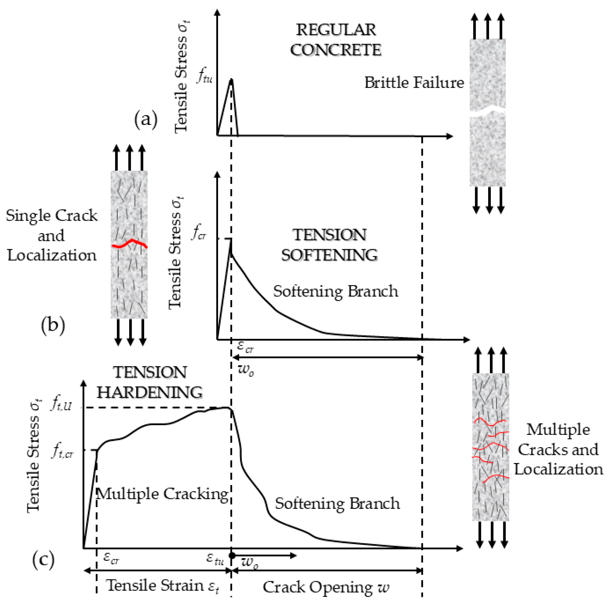
26]. However, the high tensile strength and the ability of the material to sustain significant post-cracking strength over a large range of tensile strain beyond cracking are the most attractive attributes of this material.
Figure 1 shows the stress–strain response in tension of UHPC compared to regular concrete. Depending on the fiber content, the stress–strain response after cracking may be either gradually softening in tension (TS-UHPC), marked by the localization of strain (
Figure 1b), or tension hardening (TH-UHPC) [
27]. In the latter case, the extensive post-cracking strain capacity (in the range of 0.2% or more, i.e., more than tenfold the cracking strain) is a result of the smeared distribution of multiple fine cracks (
Figure 1c). In the figure, the strain axis of TH-UHPC is offset to the left so that the onset of localization lines up between the three cases.
Several experimental studies on the performance of UHPC jackets have been reported since 2010. The most studied parameters are the specimen cross-section, scale, degree of detailing, and aspect ratio. Concerning the cross-section, most studies have investigated rectangular [
29,
30,
31,
32,
33,
34,
35,
36] and circular cross-sections [
6,
37,
38,
39,
40,
41,
42], while there are also studies on hollow cross-sections [
43,
44]. The most common specimen scale is 1:2 [
33,
34,
35,
36,
37,
39,
45], with 1:1 [
31,
38,
46] and 1:4 [
6,
42,
44] also prevalent. Fewer studies have been performed on scaled specimens with scaling from prototype dimensions at 1:5 [
40] and 1:6 [
41]. Regarding the degree of detailing, it is noted that, depending on the category of UHPC (TS or TH), transverse reinforcement may have been added inside the jacket or eliminated on account of the strain-hardening property of the jacket. Where material characterization in tension indicated a TS-UHPC response (usually for fiber content of less than 1.5%), reinforcing grids were often used to reinforce the jackets [
4,
6,
34,
45]. In the remaining discussion, this additional reinforcement amount is defined by the area ratio of the horizontal bar area
, through the jacket thickness
, over the horizontal bar spacing,
:
. Depending on the reinforcing arrangement of TS-UHPC jackets, the post-yielding range may be limited by local jacket failure [
7]. In the case of TH-UHPC jackets, several tests have been reported where no additional transverse or longitudinal reinforcement was added. These jackets have been shown to be particularly effective in mitigating shear failures and in enhancing the development capacity and ductility of lap-spliced connections above the column–footing interface [
6,
7,
31,
37,
47].
The principal functions of UHPC jackets when applied in the critical regions of columns are (a) the confinement of the encased member owing to the sustained tensile strength that hinders the lateral dilation of the encased core, which enhances the shear strength of the encased member and the lap splice development capacity of the bars anchored within the jacketed region, and (b) the development of normal (i.e., longitudinal) stresses in the member cross-section that enhance the flexural and shear strength of the component. It has also been shown that, in the case of TH-UHPC jackets with thicknesses greater than 30 mm, the plastic hinge zone may be relocated outside the jacket on account of the increased shear demand [
48]. In the retrofitting of structures to perform under lateral loads, this intervention may be used either for strengthening or for the repair of damaged components (caused by either previous loading or corrosion damage) [
4,
6,
33,
34,
35,
38,
40,
41,
44,
45,
46,
49]. Since UHPC demonstrates high tensile strength, small jacket thicknesses (less than one tenth of the section dimension) may be used. As an alternative strategy, the section in the plastic hinge region may be completely replaced [
30,
37].
UHPC cover has been shown to significantly enhance the bond strength of reinforcements embedded in this material—the bond strength is in the order of 1.3
, leading to very small required development lengths for the encased longitudinal bars, in the range of 8–10
, where
is the developed bar diameter and
is the compressive strength of UHPC [
50,
51,
52,
53,
54,
55]. However, an undesirable side effect of this enhanced strength is the extreme localization of the bar strain at crack locations or cold joints. Under large lateral displacement reversals, this effect may expedite the rupture of the bar at locations of maximum strain demand (e.g., at the column–footing connection). To moderate the bond stress and enable strain penetration over an adequate length beyond the critical section, researchers have proposed various alternatives that mitigate strain localization, such as bond breakers [
8,
47,
48], turned bars [
41], and Ni-Ti shape memory alloy (SMA) bars [
29].
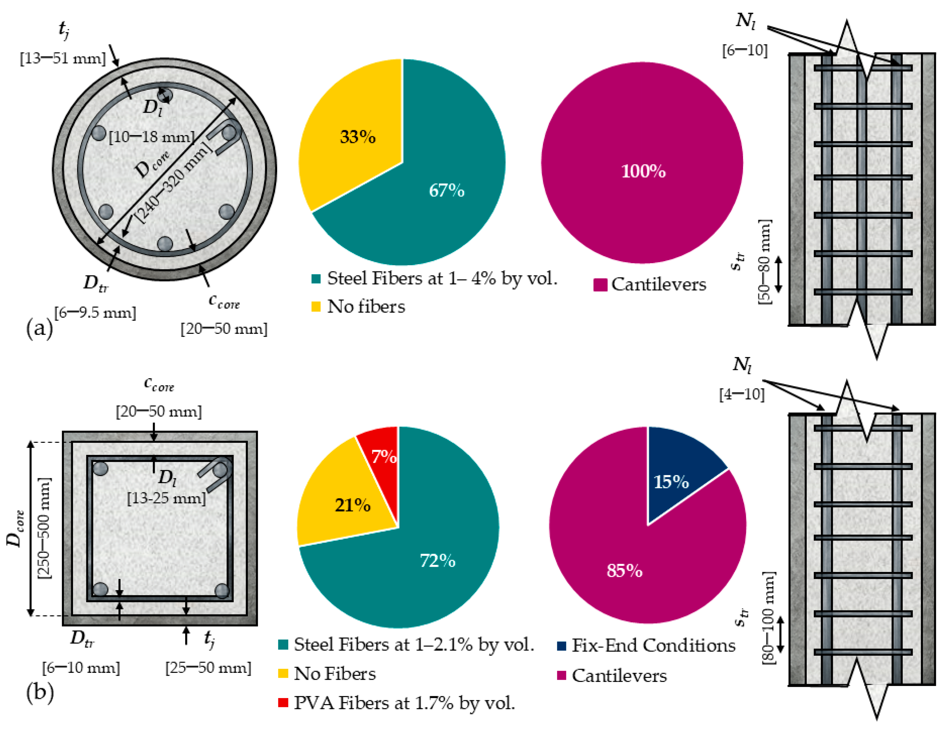
To derive detailing procedures for retrofitting regarding the lateral load resistance of columns using UHPC jacketing, a database with experimental results from circular and rectangular cross-section columns has been assembled [
17]. This database consists of a total of 80 specimens, of which 21 had a circular cross-section (denoted as C-specimens) and the remaining 59 had a rectangular cross-section (denoted as R-specimens).
Figure 2 summarizes the key details of the two groups of specimens.
For the C-specimens found in the experimental literature, only brass-coated straight steel fibers were used, with a length of 13 mm, diameter of 0.2 mm, and Young’s modulus of 200 GPa. The experimental database for R-specimens includes cases with PVA or hybrid combinations of synthetic fibers besides steel fibers.
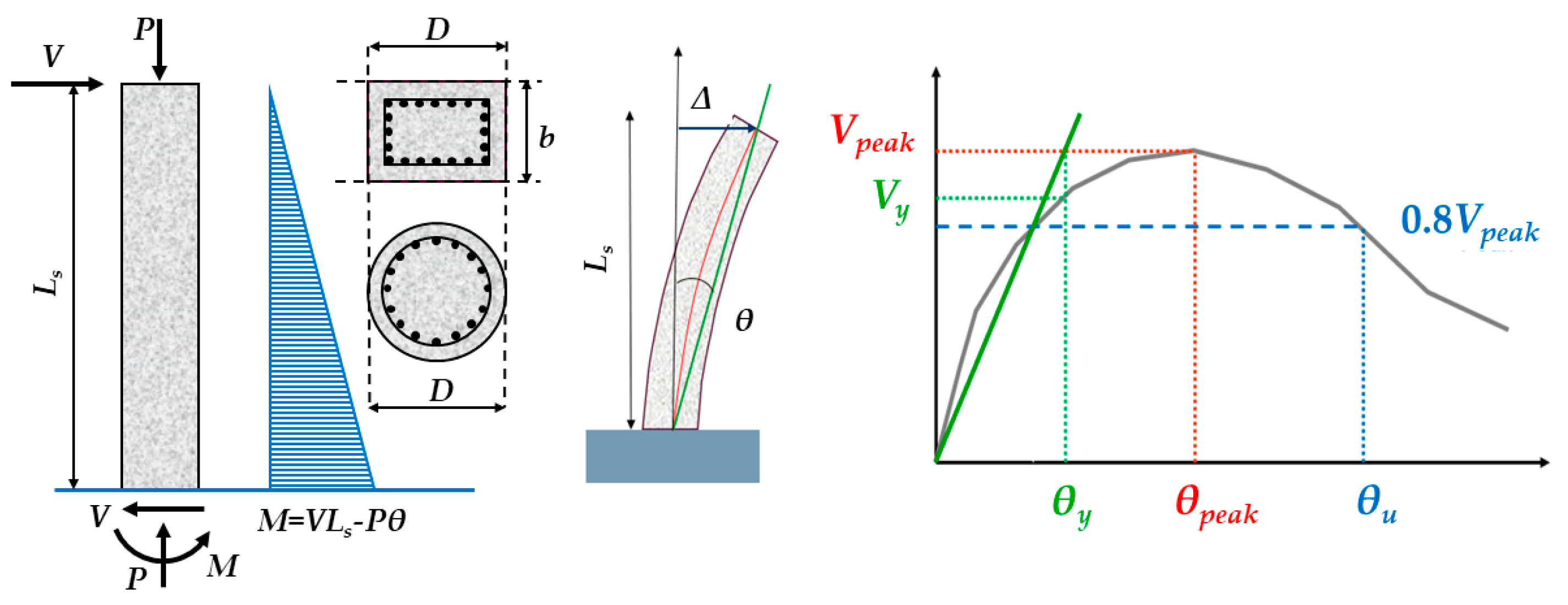
The drift capacity and strength increase achieved over the nominal flexural strength of the columns as quantified through tests of the columns in pristine conditions before jacketing are used in this study (using member response analysis [
56]) for specimens of either of the two cross-section types, in order to gauge the effectiveness of the retrofit. Load and drift ratio values at milestone points in the response curves were collected, as shown in
Figure 3. The drift ratio
was defined as the lateral displacement
Δ divided by the shear span,
, of each column experiment. The shear span for C- and R-specimens was in the range of 1400–1800 and 450–5800 mm, respectively.
To obtain an unambiguous definition of the response at the ultimate limit state, the lateral drift capacity at the post-peak point in the envelope that corresponds to 80% of the maximum lateral load (at a lateral load post-peak reduction of 20% of the strength) was used. Another important parameter was the aspect ratio,
, calculated as the ratio of the shear span (
) divided by the diameter of the C-specimen or by the depth of the R-specimen cross-section (
). Where yielding values were not reported by the researchers, notional yielding was assigned at the point defined by the intersection of the radial green line at 80% of the envelope with a horizontal line drawn at peak load (
Figure 3) (the coordinates of this point were the lateral drift and corresponding strength, considered to identify the notional yielding point).
3. Alternative Arrangements of UHPC Jacketing Systems
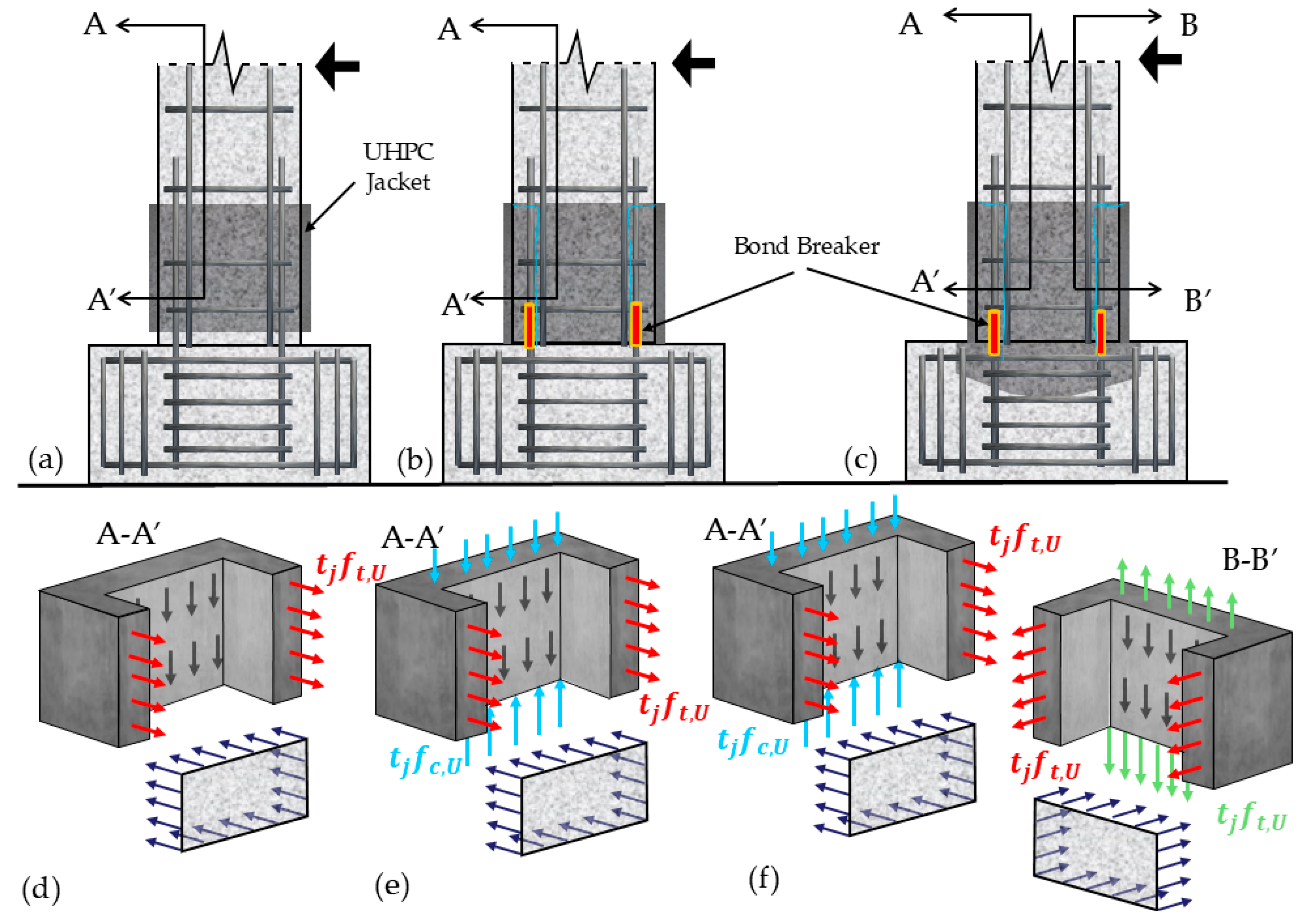
The application of UHPC jackets in the retrofitting of piers may be implemented using three different alternative arrangements, organized in order of the increasing extent of invasiveness and efficiency of intervention, as depicted in
Figure 4: (i) jacketing in the plastic hinge zone but allowing a non-contact gap between the jacket and footing (
Figure 4a); (ii) jacketing directly on the pier, thereby forming a cold joint connection between the existing concrete (footing) and the jacket (
Figure 4b); and (iii) the penetration of the jacket into the footing (
Figure 4c). In all three arrangements, the UHPC jacket exerts some confining pressure on the encased concrete member.
In the first case, the UHPC jacket provides only confinement to the encased concrete (
Figure 4d), with the gap between the jacket and footing enabling minimal tension strain spreading in the longitudinal encased reinforcement, firstly within the gap length, but also strain penetration in the adjacent regions above and below the gap. The objective in this case is to prevent the localization of the strain of the bars in tension, thereby mitigating the risk of early bar rupture. In the cold joint arrangement (
Figure 4b), besides the confinement, the jacket participates in the compressive zone and therefore in the sectional equilibrium of the critical section (
Figure 4e). In the last arrangement (
Figure 4c), with the extension of the jacket into the footing, the jacket participates in sectional equilibrium by developing normal stress in both the compression and tension regions of the critical section (
Figure 4e,f). This arrangement aims to decrease the permanent damage at the column–footing connection owing to strain localization at the critical section, which would also lead to extensive strain penetration in the upper part of the bars inside the footing [
6,
39,
40,
42,
47]. In the cases depicted in
Figure 4b,c, it is recommended that bond breakers be introduced at the lower end of the jacket (at the connection with the footing) to enable strain penetration in the longitudinal bars to extend over an adequate length and to prevent local bar fracture [
7,
8].
4. A Model Interpreting the Role of the TH-UHPC Jacket
Similarly to conventional jackets, the material placed on the lateral surface of a jacketed reinforced concrete member is engaged in actions that are supported by the confining pressure exerted on the encased core. The peak magnitude of this pressure,
, is calculated as in all cases of jacketing, as described by the equilibrium model depicted in
Figure 5. It has been shown that the clamping action provided by the confining jacket pressure enhances the frictional bond between the jacket and the encased core, which represents the shear flow at the interface between the two materials and is described by Equation (1) [
9].
where
is the cohesion and
is the angle of internal friction. Interfacial tests between UHPC and plain concrete have shown
to be around 62° [
8]. The coefficient of friction is
.
The shear flow that develops at the interface between the jacket and the encased member is responsible for the monolithic action of the jacketed part of the member and, thus, for the engagement of the jacket in the sectional equilibrium. The weakest section of the retrofitted member is at the gap or at the cold joint formed between the jacket and footing, where the longitudinal normal stresses in the jacket are either zero (
Figure 4a,d) or can only be developed under bearing, i.e., only in the compressed part of the cold joint (
Figure 4b,e). In the case of the extended jacket into the footing, the longitudinal tensile (
) and compressive stresses (
) that develop in the jacket walls participate in the flexural action of the critical section, as depicted in
Figure 4c,e for the compression part and
Figure 4f for the tension part of the critical section.
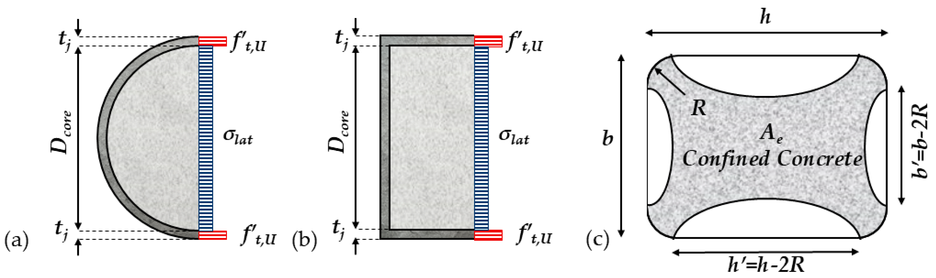
4.1. Confining Pressure, Strength, and Deformation Capacity of Encased Concrete
The simplest model describing the confining action of a UHPC jacket is used here to estimate the average lateral confining pressure
(
Figure 5 and Equation (2)), where
is the jacket thickness,
is the tensile strength of the jacketing material, and
is the yield strength of any horizontal reinforcement added in the jacket at an area ratio
and bar spacing
(
Thus, as in the case of FRP wrapping, the confining pressure exerted by UHPC jackets,
, is proportional to the thickness
and the maximum hoop stress available in the jacket, i.e., the material tensile strength,
, and inversely proportional to the section size,
. In the context of the present work,
could denote the cracking stress (conservatively),
, or could be taken to be equal to a fixed fraction of the peak tensile strength,
, (e.g.,
, where
is the fiber orientation factor and
is the material safety factor, proposed to be taken equal to 0.75 for UHPC materials [
20]). The parameter
(Equation (3)) denotes the confinement effectiveness provided by the UHPC jacket, including any embedded transverse reinforcement—theoretically, this coefficient stands for the fraction of the encased area that may be assumed to sustain uniform confining pressure. The confinement effectiveness,
, for a circular cross-section is 1; for rectangular cross-sections,
has been shown to take a similar form to what is proposed for other external jacket layers (see
Figure 5c) [
7,
18,
57]:
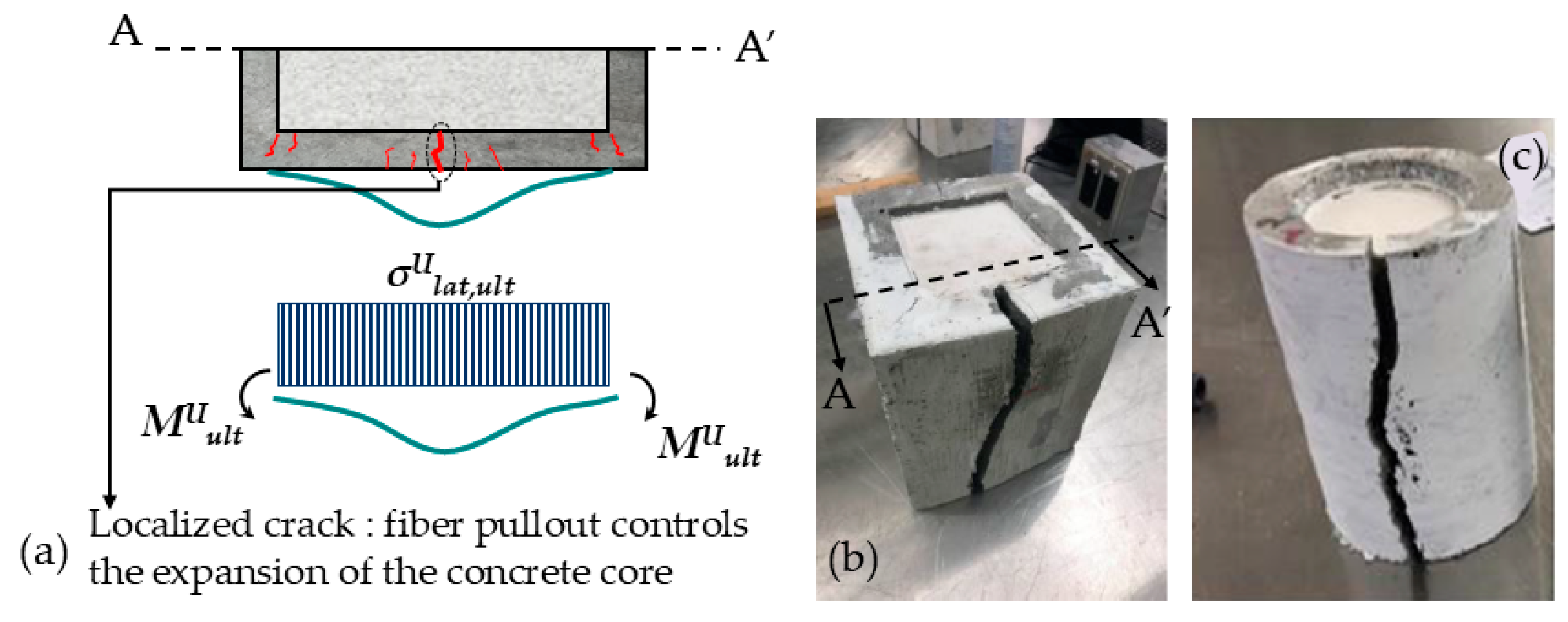
The above interpretation of the role of UHPC jacketing as a confining device overlooks the significant flexural stiffness of the jacket layer against lateral outward bending. This flexural stiffness is engaged by the outward pressure exerted by the dilating encased concrete as it approaches failure (
Figure 6a).
Experimental evidence regarding TH-UHPC-encased cylindrical and prismatic short columns has shown that while the strength increase is marginal—consistent with the passive nature of the exerted confinement—the relative deformation capacity increase is extensive, and it is actually more evident in rectangular rather than in circular sections. To address this effect, Tsiotsias [
48] proposed different confinement factors for the peak compressive strength
and ultimate deformation capacity
of TH-UHPC-encased concrete as per the following expressions (Equations (4) and (5)):
where
In Equation (5),
is the total normalized lateral pressure, which includes contributions from the UHPC material and any other form of transverse reinforcement either pre-existing in the member or added in the jacket (In Equation (6)).
is the volumetric ratio of the pre-existing transverse steel reinforcement in the column,
is the confinement effectiveness, and
is the yield strength of the transverse steel reinforcement):
The values for the
and
coefficients were calibrated by Tsiotsias [
48] against the experimental results as follows:
and
. To model the complete uniaxial compressive stress–strain response of encased concrete, a stress–strain model routinely used for conventional concrete, such as the Hognestad parabola [
58], is used to describe the ascending part of the response up to the point with coordinates
that corresponds to the peak strength of plain concrete (Equation (7)). (The reason for this is to ensure that confined concrete has at least the same initial stiffness as unconfined concrete). Thus,
A linear segment is used to model the response from a point with coordinates
up to the peak strength of the TH-UHPC confined concrete, with coordinates (
), where the strain
at the attainment of the confined strength
is given by [
59,
60] Equation (8):
Therefore, for this segment, the expression of the stress–strain model of confined concrete is described by Equation (9):
The stress model includes a plateau at constant strength equal to
up to the attainment of the ultimate strain
(which is determined from Equation (4) considering that, for conventional concrete,
). To model the post-peak response, a descending branch is assumed, which corresponds to the degrading response of the jacket in tension after the localization of failure along a vertical crack, which is the usual manner by which jackets fail (see
Figure 6b,c). Tsiotsias [
48] recommended a linear decay to a residual (constant) stress of
at a strain that is 3 (for prisms) to 4 (for circular sections) times the value of
but not less than
.
4.2. Stress–Strain Relationships of UHPC in Tension and Compression
In light of the UHPC jacketing retrofit arrangements outlined in
Figure 4, the derivation of recommendations for the dimensioning of the retrofitting of bridge piers using TH-UHPC jackets requires the use of descriptive models of the constitutive behavior of TH-UHPC subjected to tension and compression. The stress–strain models used in this study are adopted from [
57], while the actual response of TH-UHPC in tension is depicted in
Figure 7a. Meanwhile, for design purposes, the hardening stage is neglected, as shown in
Figure 7b [
20]. The randomness of the fiber orientation is particularly relevant in large-scale members and is accounted for through the reduction factor
. The compression model (
Figure 7c) is a simplified version of an analytical model that was established after using a large experimental database on uniaxial compression tests available in the literature. The ascending branch is defined through a linear relationship between stress and strain in compression up to a strain not exceeding the value of
0.003. The usable compressive strength of UHPC is taken to be equal to
, where the material safety factor is taken to be equal to 0.75 [
44]. The maximum usable strain at the extreme concrete compression fiber cannot exceed 0.004, so as to mitigate the risk of abrupt UHPC cover compressive failure, since this occurrence would eliminate the significant force resultant from the sectional equilibrium with excessive damage due to redistribution. As shown in
Figure 7c, a plateau is defined up to this strain magnitude, which is owing to the reduced effective compressive strength of the UHPC material (if taken to the actual peak and not the 75% value, this plateau would not be visible). It is noted that, based on a collective evaluation of the reported strain at compressive failure of TH-UHPC, the value of 0.004 is the upper limit for the strain at the onset of post-peak strength degradation [
57]. Beyond the peak, residual strength equal to 0.25 is assumed.
5. Comparison of Performance of Possible UHPC Jacket Retrofit Arrangements
To illustrate the implications of the nuances in the retrofit details depicted in
Figure 4, the sensitivity of the response of a typical bridge pier column is considered in this section as a case study. The pier model has a circular cross-section with diameter
= 1.2 m and a total height of 9.0 m; under lateral sway, the pier develops double curvature, with a shear span
= 4.5 m. The calculated monotonic moment curvature responses of the critical section are plotted in
Figure 8a and
Figure 9a; these are obtained using layered section analysis and the constitutive models depicted in
Figure 7. Next, the theoretical lateral force–lateral drift ratios are obtained after the integration of the curvature distributions using virtual work; the calculated results are plotted in
Figure 8b and
Figure 9b for two different axial load ratios,
0.1 and 0.2. The details of the analysis are as follows:
= 25 MPa, longitudinal reinforcement ratio
ρ = 1.6% including 30 M bars,
= 400 MPa steel, and lapped above the base over a length equal to 30
; the transverse hoop volumetric ratio is taken as 0.5% (10 M hoop bar at 180 mm spacing); axial load stress
= 2.5 MPa and 5 MPa. A 100 mm TH-UHPC jacket is used (ratio
= 0.085), having
= 150 MPa, with
= 11 MPa and tensile strain at the onset of crack localization
= 0.002. Note that, on account of the specimen size, a mild reduction from a 100% horizontal fiber alignment coefficient is assumed,
= 75% (i.e., min (
). For the sake of comparison, all material factors
are taken equal to 1 in the present analysis.
Figure 8 and
Figure 9 illustrate the moment–curvature and corresponding lateral load–displacement curves for an axial load ratio
of 0.1 and 0.2, respectively.
The results of the analyses illustrate that there are practically negligible differences in the theoretical flexural responses of the original (labeled as
NJ) and the jacketed column corresponding to the retrofitting scheme in
Figure 4a (lateral confinement only). One reason for the small effect on the flexural strength is the relatively low axial load ratio acting on the pier, whose strength is therefore controlled by tension reinforcement yielding. However, low axial loads are representative of bridge pier loading conditions (this is owing to the large sizes of piers relative to the overburden gravity loads of the deck and the fraction of live loads considered in the lateral load combination); however, the small impact of the retrofit shown in
Figure 4a is also due to the weak effect that passive confining pressures have on the strength. Considerably more important is the effect of the jacketing in terms of mitigating failures (i) due to web shear and (ii) along the lap splices and (iii) preventing the buckling of the longitudinal compression reinforcement; these are essential for the theoretically extensive nonlinear range of the response to be possible.
It is also observed that there is practically no difference in the flexural response in the retrofitting cases in
Figure 4b,c, although both represent a 33% increase in flexural strength over the
NJ and
Figure 4a cases. The similarity in the results of these two analyses suggests that, on account of the low axial load ratio, the extreme part of the jacketed cross-section within the tension zone of the circular section exceeds its tensile strain capacity,
= 0.002, before the attainment of the flexural strength of the cross-section. Therefore, for the large-sized pier sections examined here, the flexural strength increase is primarily dominated by the compressed part of the jacketed section, and the performance limit states need to be linked to the maximum compression strain attainable with a controlled degree of damage by the UHPC jacket. A similar response is observed in the case of the axial load ratio
0.2 (
Figure 9). The main differences between the
and
cases are that the increased axial load decreases the ductility of the
NJ column as expected, whereas the flexural enhancement observed in the retrofitting arrangements in the cases in
Figure 4b,c are greater than that in the case in
Figure 4a.
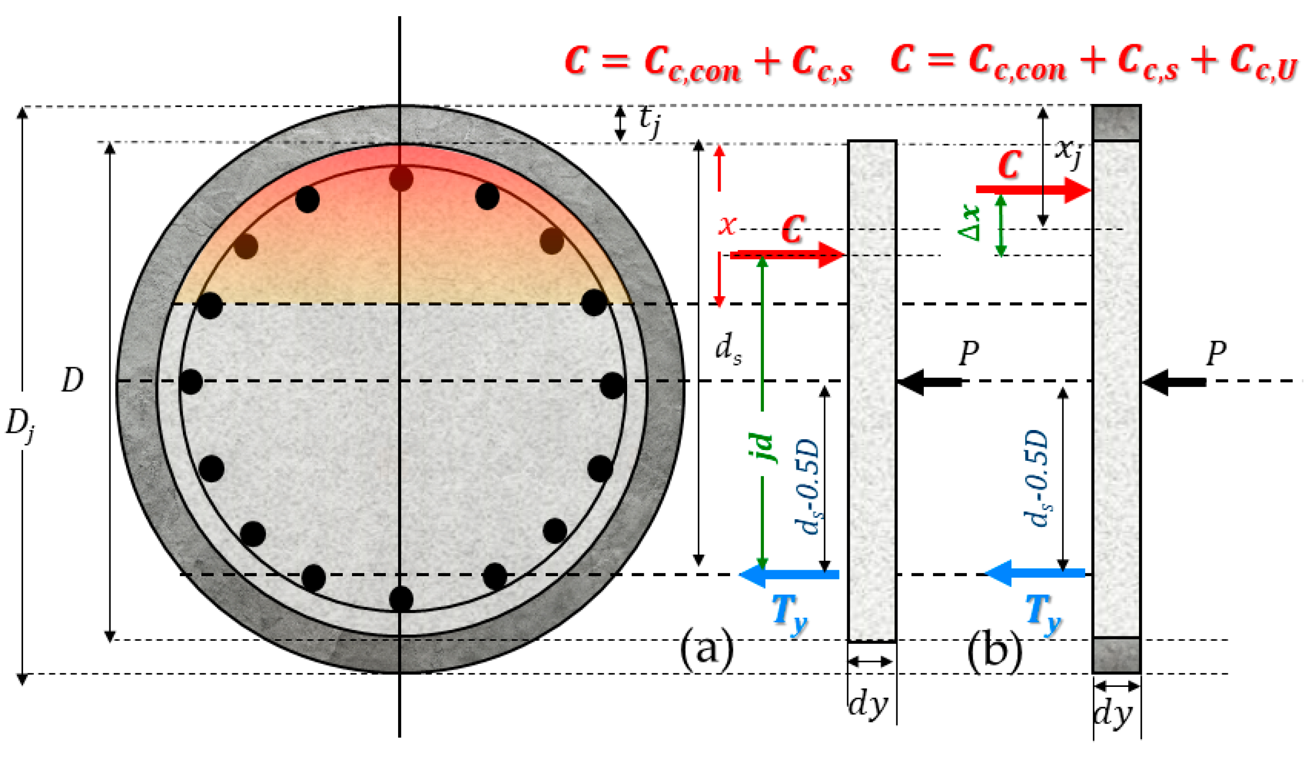
5.1. Contribution of UHPC Jackets to Flexural, Shear, and Lap Splice Strength
5.1.1. Flexural Strength Increase: Rectangular Cross-Section
For cases where the jacket participates in the equilibrium of the normal stress resultants of the cross-section (i.e., by means of the longitudinal stress resultants in the cross-sections in
Figure 4b,c), a conservative expression to assess the flexural strength increase is derived. The derivations (Equations (10) and (11)) below consider the equilibrium of the axial forces before and after the application of jacketing.
where
is the axial load in the cross-section,
is the resultant force in the tension reinforcement,
is the resultant force in the compression reinforcement, and
is the force developing in the compression zone of the concrete; these are replaced by a single compressive resultant,
, which is assumed to act at the centroid of the compression zone,
. The flexural moment strength is determined by establishing the equilibrium of the moments about the centroid of the cross section:
where
is the total height of the cross-section and
is the distance to the centroid of the tension reinforcement.
A similar approach is followed in establishing the equilibrium of the normal forces and moments in the jacketed cross-section after jacketing, as prescribed by Equation (12):
The terms
and
are the resultant normal tension and compression forces developing in the jacket’s extreme tension and compression zones, respectively, and
represents the tension forces that develop in the side part of the jacket that lies below the neutral axis. The moments about the centroid of the cross-section are obtained according to Equation (13) (
is the depth of the compression zone of the jacketed section):
where
is the distance from the point of application of
to the centroid of the cross-section (see
Figure 10). The flexural strength increase is obtained from the difference
, where the terms
and
are calculated from Equations (11b) and (13), respectively. For rectangular cross-sections, the following simplifying assumptions are made in order to obtain a versatile equation: (a) the depth of the compression zone of the jacketed section
is equal to the jacket thickness
and (b) the contribution of the side jackets to the flexural strength increase (term
) may be neglected because the point of application of the resultant is close to the mid-height of the cross-section and thus
is insignificant. Substituting for
and
, the flexural strength increase of a rectangular section with a uniform jacket thickness,
, on its perimeter is estimated as per Equation (14):
5.1.2. Flexural Strength Increase: Circular Cross-Section
For circular sections, the above simplifications are not straightforward. The depth of the compression zone is needed, while the position of the UHPC force developing in the tension zone of the jacket cannot be postulated in a consistent practical manner. To estimate the flexural strength increase provided by the jacket in this case, the stage when the reinforcement is strain hardening to strains beyond the onset of tension localization of the jacket material is considered (this is determined by analyzing circular cross-sections with low axial load ratios or containing a longitudinal reinforcement that is less than
so as to ensure that the tensile strains that develop in the tension zone exceed the nominal tensile strain capacity of the jacket (which is in the order of 0.002)). After the localization of the UHPC jacket layer in tension, the terms in Equation (12) become
(as depicted in
Figure 11). Considering that the term on the right-hand side remains approximately unaltered after the tension failure of the jacket, it is concluded that the compression stress resultant,
, is also approximately constant; therefore, the flexural strength increase is owing to the change in the position of the stress resultant from the centroid, due to the change in the depth of the compression zone after jacketing.
To check this assumption, the depth of the compression zone (normalized with the diameter
of the original cross-section) is examined for the pier example in
Figure 12 for two different values of the axial load ratio
(=
= 0.1 and 0.2); the abscissa in the figure is the total longitudinal reinforcement ratio. Again, a layered section analysis was conducted to obtain the depth of the compression zone and the position of the compression force resultant in the jacketed cross-section, using the material constitutive models described in the above. For the selected jacket material properties and jacket geometry considered in this case study, it was observed that the original depth of the neutral axis was in the range of 0.27
to 0.33
for
ν = 0.1 and from 0.36
to 0.4
for
= 0.2, whereas the addition of the jacket reduced the depth of the compression zone by 0.15
for
= 0.1 to 0.2
for
= 0.2. This reduction in the compressive zone depth,
leads to an equal increase in the lever arm of the resultant compressive force
to the centroid of the cross-section. The jacketed section’s flexural moment resistance is thus obtained from Equation (15):
where
is the flexural moment strength increase effected by the jacket;
is the flexural strength of the original cross-section, and
where
is the initial lever arm of the unstrengthened cross-section (≈0.75
). The term
is obtained from Equation (15c) using the flexural strength of the unretrofitted member,
:
Upon substitution in Equation (15b), the following simplified approximation for the flexural strength increase,
, that results from the addition of the jacket is calculated for the axial load ratio and jacket properties considered:
In the above equation, stands for the distance of the tension reinforcement from the extreme compression fiber of the jacketed cross-section. Equation (15d) corresponds to the increase in the lateral load flexural resistance of the pier equal to ; note that the increased shear demand in the region above the end of the jacketed section needs to be checked against the available shear strength of the original member.
5.1.3. Shear Strength Increase with the Addition of the UHPC Jacket
For low axial load ratios, the nominal shear strength of the original cross-section,
, is calculated as the sum of the concrete contribution
and the contribution of transverse steel
. For low axial loads, the additional contribution of the axial load is neglected; thus, according to CSA-S3 2019 [
20,
61] and Equation (16a),
where
, and
Av is the area of a single layer of transverse reinforcement intersecting with a crack inclined with respect to the longitudinal axis at an angle
and spaced in the longitudinal direction at spacing
s. In this simplified method of calculation, the parameters
and
are taken equal to 0.18 and 35° (
For circular section piers, the following expression has been proposed by Ang et al. [
62]:
In Equation (16b),
s is the hoop spacing and
is the hoop bar area (a single hoop);
is the effective depth of the shear resisting part of the cross-section (taken in approximation as 0.8
); and
is the angle of diagonal cracks with respect to the longitudinal axis (see
Figure 13). Ang et al. [
62] recommended taking
for a spirally reinforced circular section (note that the difference in the value of
used in the rectangular and the circular section approaches has a negligible effect on the value of
. Based on the collective experimental evidence [
17,
63], it has been observed that the web shear strength increase resulting from jacket addition mitigates the likelihood of shear failure, even after the above flexural strength increase. Equation (16c) is used to determine the enhancement in the shear strength contributed by the jacket, where
is the design tensile strength of the material, which is taken to be equal to min (
;
is the external diameter of the jacketed section; and
for rectangular and
for circular sections:
After jacketing, shear failure may be considered to be mitigated provided that
by a significant margin (in designing members for lateral load resistance using conventional concrete, 40% shear overstrength is recommended, i.e., the shear strength is required to be 1.4 times the flexural shear demand, on account of the degradation of concrete’s shear resistance upon cyclic loading (ASCE-SEI 41/2023 [
64]; for columns, the user is directed to ACI 318-19 [
65], Chapter 21, Section 21.2.4.1). However, a less conservative factor may be enabled in the future as more experimental results are collected from UHPC-jacketed columns, since the degradation is significantly mitigated when using UHPC materials.
5.1.4. Lap Splice Strength Increase with the Addition of the UHPC Jacket
The lateral pressure provided by the cover and the hoops crossing the development length of the lap splices provide the essential clamping action that enables the development of the reinforcing bars; the frictional model expression [
66,
67] has been used in the past to quantify the bar development capacity, as prescribed in Equation (17):
The frictional coefficient
for ultimate load applications is usually taken as
; moreover, the clamping contribution provided by the cover is eliminated upon splitting failure, which occurs after bar yielding; therefore, it is usually neglected. In the example considered, Equation (14) results in a maximum developed force of
of about 75% of the yielding strength of the bar; therefore, the vertical dashed line on the left of the moment curvature diagrams in
Figure 8a and
Figure 9a represents the limit of lap splice failure for the circular pier studied. Thus, the benefit of the jacketing option depicted in
Figure 4a is that it enables bar yielding and the development of a significant part of the inelastic range of response in the moment–curvature diagram beyond the limiting boundary shown in the plot. The revised expression after accounting for the jacket contribution is given by Equation (18):
where
is the lateral confining pressure provided by the jacket (Equation (2)) and
is the minimum value between the length of the jacket and the available lap splice length. For the jacket to be adequate, the right-hand side term of Equation (17) should exceed at least the yield strength of the bar to provide some capacity for redistribution after yield penetration over part of the lap length. According to the design charts provided by Tastani and Pantazopoulou [
68], for good bond conditions, a
30 anchorage length can support strain ductility in the reinforcement of the order of 9 (i.e., a nonlinear bar strain in the order of 0.018) for high strain-hardening reinforcement; this ductility is increased to 25 for low strain-hardening reinforcement (i.e., bar strain in the order of 0.05). Therefore, although the flexural strength increase with the addition of the jacket according to the scheme in
Figure 4a is negligible, it is found that it enables the development of the flexural strength up to a large strain limit (the point depicted with a circular marker in
Figure 8a and
Figure 9a is the lower case of nonlinear strain of 0.018 and that with a rhomb marker denotes the higher nonlinear strain option of 0.05), while also mitigating shear failure.
5.1.5. Limitation of the Deformation Capacity of Jackets Bearing on the Footing
In the absence of a separating gap above the footing, it was found that the jackets in Schemes in
Figure 4b,c enable the attainment of a strength increase in the order of 33% of the original nominal flexural resistance by bearing action directly on the footing. A failure mode that needs to be mitigated by controlling the amount of lateral drift demand in the column is the increased compression strain in the compression zone, effected by the localized reinforcement pullout slip,
, which occurs in the tension zone (
Figure 13). The kinematic relationship that relates the localized compression strain increase
with tension reinforcement pullout is described by Equation (19) [
69]:
where
ds is the distance of the tension reinforcement from the extreme compression fiber of the jacketed cross-section, and
x is the depth of the compression zone (
Figure 13c). Based on the study presented in the above, under good bond conditions, as would be provided by the jacket over an anchorage length of
30 the maximum pullout slip before the complete bond failure of the rebar is in the range of
0.3 = 9 mm for the strain ductility of 9 that was determined above, assuming a moderate amount of reinforcement strain hardening. Using
= 1250 mm, and the result for
0.12 = 145 mm found earlier, this leads to
= 0.00095—this strain can accelerate the compression failure of the outer layer of the jacket. The increment
is exacerbated further with increasing crack opening above the footing in the tension zone, rendering the compression failure of the jacket at the toe of the pier a likely contingency for arrangements according to
Figure 4b,c.
5.2. Performance According to the Experimental Evidence
The analysis of the experimental evidence assembled in the database provides insights into the effectiveness of confinement on the encased concrete’s behavior, the deformation capacity, and the attainment of flexural strength, which can be correlated with the analytical findings of the preceding section and can be used to support the development of methodologies and recommendations for this retrofitting method. Considering that the hoop stress in the jacket is proportional to the fiber content (
) and the jacket thickness
, a confinement index is used to organize the experimental data. This is an estimate of the confining stress normalized by
; it is symbolized henceforth by
JI, and it is calculated according to Equation (20), to account for the role of the important variables mentioned above. It is noted, however, that for a random distribution of fibers (random casting), the actual value of
JI may be lower than the nominal value calculated with Equation (20) by as much as 75% to 35%. For the present study, as the method of casting is unknown,
JI is considered a nominal confinement index.
For retrofits that have FRP grids as transverse reinforcements instead of steel stirrups, the term
is replaced by the product (
0.002), where
is the elastic modulus of the FRP material and 0.002 represents the localization strain of the UHPC jacket in which the grid is encased. It is also noted that there are certain characteristics of the original column that may either hinder or enhance the deformation capacity, as follows: (1) the presence of a large amount of longitudinal reinforcement increases the lateral force demand required to cause the flexural yielding of the column, thereby predisposing the column to shear failure, whereas (2) high axial ratios and low aspect ratios compromise the deformation capacity, and transverse reinforcement has a positive impact on this property. The effect of these parameters on the characteristics of the mode of column failure is similar even after jacketing. To account for these parameters, a composite index (
CI) is computed to classify the experimental values of the ultimate drift capacity and is described by Equation (21).
CI is proportional to the transverse reinforcement ratio (
) and aspect ratio of the column (
) and inversely proportional to the longitudinal reinforcement ratio (
); here, all of the longitudinal reinforcement is included in the calculation of this parameter, assuming a symmetrically reinforced column. The parameter
CI decays linearly with the increasing axial load ratio
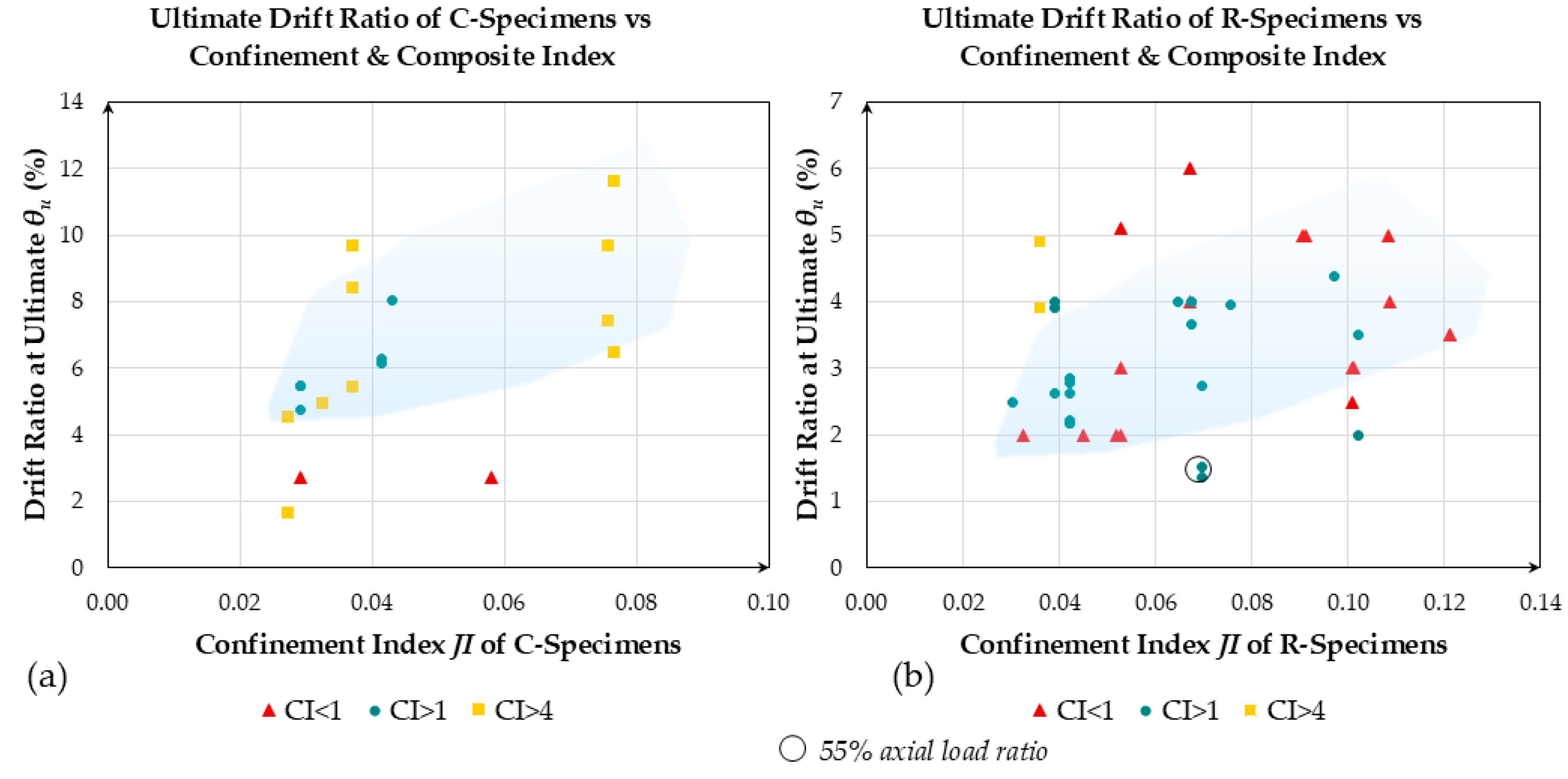
. The influence of both indices on the drift capacity
is illustrated in
Figure 14.
It is noted that C-type sections generally attain higher drift capacities
, (i.e., more than 4%; see
Figure 14a) as compared to R-type sections (the lower limit was 2%; see
Figure 14b), with the value of
showing a relatively mild increase and significant dispersion with the increasing magnitude of the index
CI. The volume of the available data is still limited in terms of supporting the derivation of a detailed analytical expression; however, the proposed index is effective in reproducing the experimental trend, which is an increase in drift capacity with an increasing amount of confinement and value of
CI.
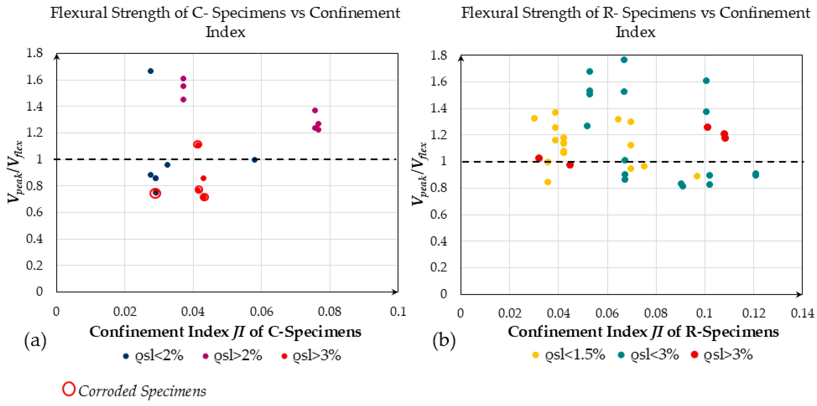
Using the initial flexural strength of the cross-section and the additional flexural strength provided by the jacket as described in Equations (14) and (15d), the lateral force
required to support a flexure-dominated response can be determined, according to Equation (22):
The lateral force that takes into consideration the enhanced flexural strength due to the TH-UHPC jacket is compared to the maximum experimental lateral force of each specimen in the database. The results are plotted against the confinement index
JI in
Figure 15.
Specimens having values of the ratio
indicate that another form of failure—other than extensive flexural yielding—may have occurred (e.g., jacket toe crushing or shear failure above the end of the jacketed region), limiting the effectiveness of the retrofit (
Figure 15). It is noted that, for C-type columns, most of the points that fall below the horizontal line at 1 correspond to columns that had been previously corroded. Specimens that present a
JI of less than 0.25 were able to reach their nominal flexural strength only when they were underenforced (i.e.,
< 2%); shear failures were mitigated above the retrofitted zone of the column in these cases. The values of the
ratio exceeded 1 by a substantial margin only when the original reference column had experienced premature failure in the critical region. In these cases, the difference between the original and the retrofitted column was exaggerated because the experimental value of the reference lateral strength, which enters the value of
in Equation (22), was underestimated as compared to the nominal flexural resistance of the column. Such failures were seen in cases of an excessive axial load (
> 0.2) or when the longitudinal reinforcement ratio in the encased member,
, exceeded 2%, as well as in cases where insufficient transverse reinforcement was provided in the critical region [
18,
53].
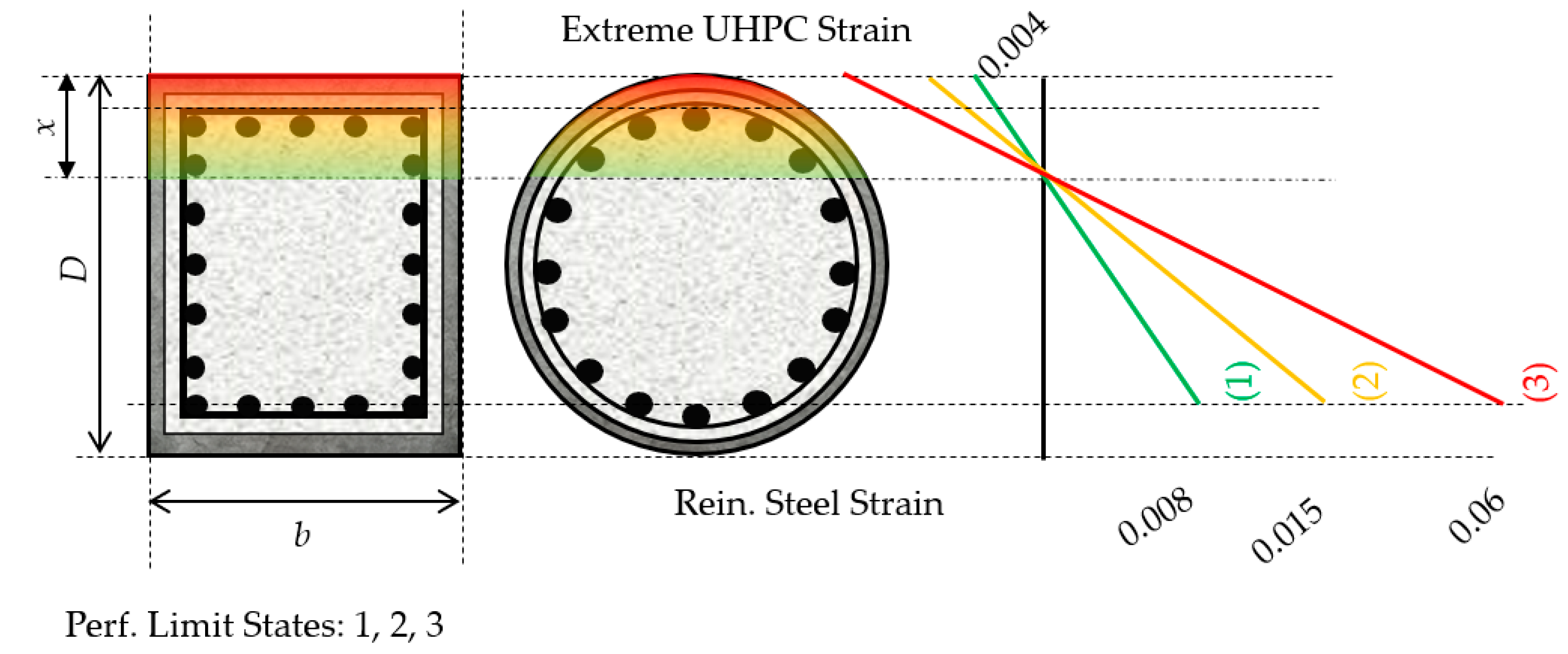
5.3. Recommended Performance Limits for Retrofitting with TH-UHPC Jacketing
Consistent with the prevalent methods of evaluation of existing structures regarding lateral loads, it is of interest to develop the formulation of UHPC retrofit solutions that are compatible with a performance-based framework. After a detailed evaluation of the available experimental evidence on UHPC material characterization and the reversed cyclic load testing of UHPC-jacketed components [
7,
58,
64], pertinent detailing provisions refer to three different performance objectives (
Figure 16) as follows [
20,
65].
Minimal Damage—UHPC jacket strain in compression ≤0.004, longitudinal reinforcement tension strain ≤0.008. In the CSA-S6 [
20], this refers to cover crushing and delamination in conventional concrete piers as the first indication of notable distress. These two criteria are intended to limit the requirement for repairs under a frequent-intensity earthquake (20% probability of exceedance in 50 years)—such as the local crushing of the jacket in compression and significant bar pullout from the footing. It is noted that, based on the experimental evidence summarized by Mohamed et al. [
58], UHPC attains its uniaxial compressive strength at strains in the range of 0.004–0.005. A counter-argument to the compression strain limit chosen for the minimal damage limit state is that the enhanced strain capacity of the encased concrete would not be exploited at this stage. It is noted, however, that, with reference to frequent earthquake events, a primary requirement for the retrofit scheme is the continued functionality of the retrofit. In this context, a higher level of damage in the extreme fibers of the compression zone of the jacketed section would not be warranted.
Repairable Damage—The tensile strain in longitudinal reinforcement is limited to 0.015. This value is extended from what is valid for the conventional seismic design of bridge piers for the repairable damage performance limit state. It is noted that strain reversal from this strain level has been linked to reinforcement buckling for conventionally confined cross-sections, whereas, here, it was shown that short lap splices or anchorages may accelerate crushing at the toe of the UHPC jacket on account of pullout rotations for these levels of strain. Therefore, this limit heralds the onset of serious damage beyond which repair may not be possible.
Life Safety Limit—The damage sustained by the member should not cause the crushing of the encased concrete core, whereas the reinforcing steel tensile strains should not exceed a nominal strain of 0.06. It is noted that this is a conservative limit for bar fracture. This limit is necessary for cases where the main reinforcement has been previously embrittled by corrosion. Another reason is that the significant confinement exerted by the jacket has been shown to enhance reinforcement to concrete bond, thereby limiting strain penetration and leading to severe strain localization at the critical section, with an increased likelihood of bar fracture at elevated levels of lateral drift.


