Article

Self-Compacting Cementitious Composites with Heavy Fuel Fly Ash Replacement

by
Antroula Georgiou
1,
Nicolaos Chousidis
2 and
Ioannis Ioannou
1,*
1
Department of Civil and Environmental Engineering, University of Cyprus, 1678 Nicosia, Cyprus
2
School of Chemical Engineering, National Technical University of Athens, 15780 Athens, Greece
*
Author to whom correspondence should be addressed.
Constr. Mater. 2022, 2(4), 276-296; https://doi.org/10.3390/constrmater2040018
Submission received: 10 October 2022 / Revised: 31 October 2022 / Accepted: 3 November 2022 / Published: 10 November 2022
(This article belongs to the Special Issue Advances in Concrete Binders and Reinforced Concrete)

Abstract

:
Sustainability in construction is related to the use of industrial by-products, such as fly ash (FA). FA varies in chemical/mineralogical composition, depending on the raw materials burnt during its production. While FA produced from coal-fired power stations is extensively used in cementitious composites, heavy oil FA produced from the firing of heavy fuels (e.g., mazut or diesel) remains largely unused. This paper focuses on the novel use of heavy fuel fly ash (HFFA), as a replacement of Class F FA, in high-volume fly ash self-compacting composites. Two different grain size distributions of HFFA were used in quantities 5–15% w/w of cement and Class F FA for the production of the composites. The assessment of the physico-mechanical properties and microstructure of the end-products at different curing ages suggests that HFFA may be used at quantities ≤10% w/w, without any negative effects. In fact, depending on the quantity and grain size distribution of the HFFA, this may even improve some of the properties of the end-products in the long term, provided that a careful mix design is adopted. The findings show the potential of sustainable reuse of HFFA and are beneficial for its incorporation into design codes.

1. Introduction

Besides waste production at the end of the useful life of a structure, the construction industry is also responsible for significant CO2 emissions throughout the lifecycle of a building. The production of Portland cement alone is responsible for 5% of global CO2 emissions: producing a ton of cement requires 4.7 million BTUs of energy, which is equivalent to about 180 kg of coal, and generates nearly a ton of CO2. Cement production is growing by 2.5% annually, and is expected to rise from 2.55 billion tons in 2006 to 3.7–4.4 billion tons by 2050, with an equivalent amount of CO2 emitted into the environment [1]. In addition to CO2 emissions, cement and concrete are also responsible for the consumption of large quantities of limestone, clay and energy, as well as for the use of water and crushed aggregate.
According to the 1987 UN definition, “sustainable development” is “development that meets the needs of the present without compromising the ability of future generations to meet their own needs”. With the increasing development of the built environment throughout the globe and the trend among people in the “developing” world to adopt a consumer-driven lifestyle, the question of concrete’s sustainability gains a new perspective. Recycling (e.g., of aggregates) is encouraged in order to reduce the amount of raw materials and the cost/energy required for the production of cementitious composites. In this framework, the use of industrial by-products in concrete production, as a replacement for cement, is also gaining increasing attention. One of the most promising attempts for the sustainable development of concrete is the use of fly ash (FA), a by-product of the energy industry that otherwise ends up in wastelands, adding to existing environmental problems [2,3]. Depending on its classification, FA may be used in concrete as a cement replacement at a maximum amount of 40% w/w [4]. FA in cementitious composites acts as an artificial pozzolan, reacting chemically with calcium hydroxide (C-H) to form compounds possessing hydraulic properties, such as calcium silicate hydrate (C-S-H). Previous reports confirm the beneficial effect of FA addition in concrete production [5,6,7]; however, pozzolanic concretes also demonstrate some drawbacks, such as low early strength and delayed setting time, while pozzolanic cementitious materials are subject to more extensive carbonation compared to OPC [8,9,10].
A previous study [11] proved the beneficial effect of fly ash addition on the performance of concrete; in this research, the physicomechanical properties of the hardened end-product were improved with FA addition in low proportions (5% and 10% w/w cement replacement). Another relevant study [12] has shown that the performance of hardened FA concrete depends not only on the CaO and SiO2 content of the additive, but also on its fineness, free lime and sulfate ion content. In particular, the durability properties of concrete containing fly ash with high SO3 and CaO contents improved, while concrete containing fly ash with significant amounts of clay minerals exhibited low chloride penetration resistance and strength.
This paper focuses on the use of Class F FA in high volumes, as a replacement for cement, for the production of self-compacting composites. Such composites may serve as the matrix of an ultra-high-performance concrete (UHPC) or fiber-reinforced cementitious composite, since their self-compacting properties and the absence of coarse aggregates minimize stress concentrations. Additionally, they may be used as repair material on the structural elements of existing structures that require minor patch repairs. Heavy fuel (oil) fly ash (HFFA) originating from a power thermal station operating in Cyprus has also been used in the mix designs, at various proportions replacing the lignite FA, in an effort to investigate the effect of this by-product on the laboratory-produced cementitious composites. The latter have been tested in compression and flexure at various ages to determine the effect of FA on their stiffness properties, following the delayed reactivity this industrial by-product shows due to its pozzolanic nature. The capillary absorption, porosity and bulk density of the hardened composites were also determined, and their microstructure was analyzed with scanning electron microscope (SEM). It is worth noting that the HFFA produced in the two power stations operating in Cyprus has not been used in concrete production to date, since it has not been studied at all in the past; hence, the present study is timely.

2. State of the Art on the Use of Fly Ash in Concrete

FA consists of glass spheres 0.01–100 μm in size, with a typical particle size diameter in the order of 50 μm [13]. Due to its particle fineness and spherical shape, good-quality, low-carbon content FA reduces friction among all concrete particles in the fresh state, thus increasing the workability of the mixture and subsequently reducing its need for water. In fact, Thomas et al. [14] reported a reduction of 3% w/w in water for every 10% w/w cement replacement by FA. This water reduction eventually leads to an increase in the hardened composite’s strength. The spherical shape of FA particles also increases concrete consolidation and reduces mix segregation. Another reason for using (good quality) FA in concrete is its low setting rate [15] and the reduction in the internal heat produced thereof [16]; the latter initiates autogenous shrinkage and internal micro-cracking in mass concrete structures. The low setting rate of FA may nevertheless also count as a disadvantage in cold weather concreting or if there is a need for higher concrete strengths at early ages. It is worth noting that the higher the calcium oxide content (CaO) in FA, the longer it takes for the fresh concrete mixture to set. Despite the negative effect of FA in early-age concrete mechanical properties, at later stages, FA continues to react, with the hydration products generally resulting in higher ultimate strengths and a denser concrete microstructure, provided that curing is sufficient. This denser microstructure positively affects the water/air permeability of FA concrete and therefore enhances its durability. Low-calcium content FA can also control alkali–silica reactions, due to the reduction in alkali hydroxides in the FA [14].
The first study concerning the use of FA as a supplementary material for concrete was published at the beginning of the 20th century [17]. Fly ash from coal-fired electric power plants became available in large quantities in the 1930s. In 1937, the research performed by Davis et al. [18] was used as the foundation for early specifications and methods of testing relevant to the use of FA as partial mass or volume replacement of Portland cement. In the 1940s and 1950s, further research [19] established the advantages and disadvantages of Class F FA in concrete. In the early 1950s, the Bureau of Public Roads (BPR) concluded that a substantial amount of the Portland cement in concrete could be replaced by FA, without adversely affecting the long-term strength of the end-product [20]. One of the BPR studies in the 1960s evaluated various test methods for FA and showed the relationship of the characteristics of the latter to the characteristics of mortar and concrete [21]. A new generation of coal-fired power plants was built in the U.S. during the late 1960s and 1970s, with improved processing technology that led to the production of finer FA with lower carbon content than the FA previously available [4].
In 1986, the Canadian Center for Mineral and Energy Technology (CANMET) developed the first high-volume fly ash concrete (HVFA) for structural applications [22], defined as concrete with at least 50% w/w of Portland cement replaced with FA. Research over the past few years has expanded the design of HVFA composites to include mixtures with >70% w/w of FA as cement replacement [23]. FA in high volumes was found to reduce the water demand of concrete, improve its workability, minimize cracking due to thermal and drying shrinkage, and enhance durability against reinforcement corrosion, sulfate attack and alkali–silica expansion [24]. The technology of HVFA composites can therefore be used in the development of sustainable high-performance concrete (HPC) mixtures with enhanced workability, ultimate strength and durability. The typical mix proportions of this type of composites, given by Malhotra and Mehta [25], contain coarse aggregate (maximum particle size 19 mm) and produce slumps in the range of 150–200 mm. The improved rheological properties of HVFA concrete, however, have also been exploited in the development of self-compacting mixtures, which typically exclude the use of coarse aggregates [8]. Due to the decreased need for water of these mixtures, the risk of bleeding also decreases.
FA is generally a by-product of electricity-generating power stations. Though its mineralogical and chemical composition is affected by the raw materials (anthracite, lignite, bituminous and sub-bituminous coal) used during its production and the firing conditions in the kiln, FA consists mainly of substantial amounts of amorphous and crystalline silicon dioxide (SiO2), aluminum oxide (Al2O3) and calcium oxide (CaO), i.e., the main mineral compounds in coal-bearing rock strata [26,27]. In some countries, heavy fuel oil, diesel or natural gas are used in electricity power stations. HFFA has high carbon (C) and low Si/Al contents [28]. To date, few studies have been conducted on the characterization and utilization of HFFA in cementitious composites [29,30,31], despite the fact that there are enormous quantities of this material produced every year (ca. 340,000 m3 in Saudi Arabia, 420,000 m3 in Jordan, etc.). Cyprus is one of the countries in the EU still using heavy fuel for the generation of electricity in its power stations; other EU member countries with more than 3% of their energy produced from petroleum and its by-products are Greece, Italy, Lithuania, Malta, Portugal and Spain [32].
As with FA, the fuel type and firing conditions also influence the characteristics of HFFA [31]. Even though the latter is generally rich in heavy metals, such as vanadium, nickel, iron and magnesium, that may leach and contaminate the environment [33,34], cement has been shown to be effective in immobilizing those metals [35]. Nevertheless, it was found that only ≤4% w/w of HFFA replacement of cement can produce composites with satisfactory mechanical strength, while the end-composite’s need for water and the initial setting time both increase drastically with an increasing amount of HFFA [36]. Other studies have suggested that HFFA is a non-pozzolanic material, comprising a high proportion of unburnt carbon and having a high specific surface area, together with a much lower relative density, compared to that of cement; this results in increased water demand and a reduction in the strength of flowable fill concrete. The same studies recommended a maximum 30% w/w cement replacement with HFFA for flowable fill concrete [31].
Al-Osta et al. [30] studied the possibilities of using HFFA in concrete blocks and asphalt concrete (AC) mixes, concluding that the dosage of HFFA should not exceed 15% w/w of the cement content, since higher dosages resulted in non-coherent concrete mixtures with poor binding capacity, decreased strength and lower durability. On the other hand, higher HFFA concentrations resulted in lower concentrations of barium leaching out of the block mix; this was attributed to the HFFA adsorbing the leaching elements. Hence, provided that other engineering properties are met, the authors concluded that HFFA might be used in the production of concrete blocks.
More recent studies revealed that for the optimal use of this type of anthropogenic raw material, detailed compositional, structural, textual and functional analyses are necessary. These studies, therefore, proposed an algorithm that defines the best use of HFFA (i.e., in concrete, sorbents, fertilizers, catalysts, etc.) in relation to its aforementioned characteristics [37]. Additionally, HFFA has been used to improve the mechanical properties and durability characteristics of concrete [38], as well as for the production of lightweight [39] and geopolymer concrete [40,41].

3. Materials and Methods

3.1. Raw Materials

CEM IΙ/A-M (L-S) 42.5R Portland Composite Cement, in accordance with EΝ 197-1, was used in the present study. This type of blended cement is produced locally using pure limestone, and it is typically used for the production of concrete, which is more impermeable and denser compared to OPC concrete, with a higher degree of workability and reduced plastic shrinkage, while its compressive strength at 28 days is equivalent to that of 42.5R OPC; however, at 2 and 7 days, it is superior [42].
Silica sand with a maximum grain size of 300 μm was also used. This material, which shows a narrow grain size distribution (see Table 1), comprises characteristic spherical crystal quartz particles (SiO2 content 98.6%) and a low content of accessory minerals (Al2O3, Fe2O3 and TiO2). Its Mohs hardness is 7, while its raw and bulk densities are 2.65 gr/cm3 and 1.35 gr/cm3, respectively. The use of this silica sand, besides maintaining adequate stiffness and volume stability, also helps control the toughness of mixtures without coarse aggregates by filling up their pores.
Class F FA, imported from Israel (Eurocrete), was used as a replacement for cement. This FA, which complies fully with ASTM C618 and EN 206, consists mainly of silicates, feldspars, carbon and oxides, and it contains no chlorides or other potentially harmful components (Figure 1). Its dry bulk density is 1000 kg/m3. The company providing this product suggests that it may be used as a replacement for cement in proportions ranging from 20% to 40% w/w. However, in the present study, the amount of Eurocrete FA used was >120% w/w of the amount of cement (i.e., one part of hydraulic binder material in the final mixture comprised 45% w/w cement and 55% w/w FA).
HFFA from a local power station was further used as a replacement for the imported Class F FA. This material contains large amounts of anthracene and carbon, as well as minor quantities of sulfates, calcite, goethite and other accessory minerals (Figure 1). Sieve analysis was performed on the HFFA and the results are shown in Figure 2, together with the grain size distributions of the rest of the dry raw materials used in this study. Table 2 summarizes the results of the chemical analysis for the two types of fly ash.

3.2. Mix Designs

For the benefit of understanding the performance of HVFA cementitious composites with self-compacting properties, following the partial replacement of pozzolanic (Class F) FA with HFFA, the experimental program was designed to examine a multitude of different cases, whereby varying percentages of Class F FA were replaced with local HFFA of different grain size distributions. The initial mix design adopted was based on a previous study [42], where the same mix design was used as a reference for the matrix of a fiber-reinforced cementitious composite intended for large-scale casting.
The reference mixture (PM) of the present study comprised 55% w/w replacement of cement with Class F FA, as shown in Table 3. According to a number of fresh state property tests (Table 4), this mixture may be classified as self-compacting or superfluous.
In mixtures M-5-15-F and M-5-15-C, Class F FA was replaced with different grain size distributions (d < 300 μm and 300 μm < d < 1 mm respectively) of HFFA in different percentages (i.e., 5%, 10% and 15% of the combined cement and FA weight); the quantities of water and superplasticizer (SP) were properly adjusted to maintain the self-compacting properties of the original mixture (Table 3). It is worth noting that the temperature during mixing increased with the addition of HFFA (Table 3). Other studies [43,44] have also shown that the partial replacement of cement with FA results in a temperature increase during mixing due to the heat evolving during the first few minutes of hydration. This is attributed to the delayed ettringite (C6AS3H32) formation (DEF) within the composite (see Equation (1)) [41]. The heating rate actually influences the formation of ettringite at an early age, when an additive rich in SO3 is added to the mixture; this also leads to risk of expansion due to DEF [45]. It is worth noting that the aluminum phase (C3A) is the most reactive of the four main clinker minerals (C3A, C3S, C2S and C4AF), despite the presence of gypsum, which is added to control the reaction. The hydration process, therefore, starts with the reaction of the aluminum phase with water to generate an aluminate-rich gel forming small rod-like ettringite crystals (Equation (1)); this gel then reacts with the sulfate mineral to form monosulfate aluminate hydrate (C4ASH12) (Equation (2)).
C3A + 3CSH2 + 26H → C6AS3H32, ΔH = 207 cal/g
2C3A + C6AS3H32 + 4H → 3C4ASH12, ΔH = 120 cal/g
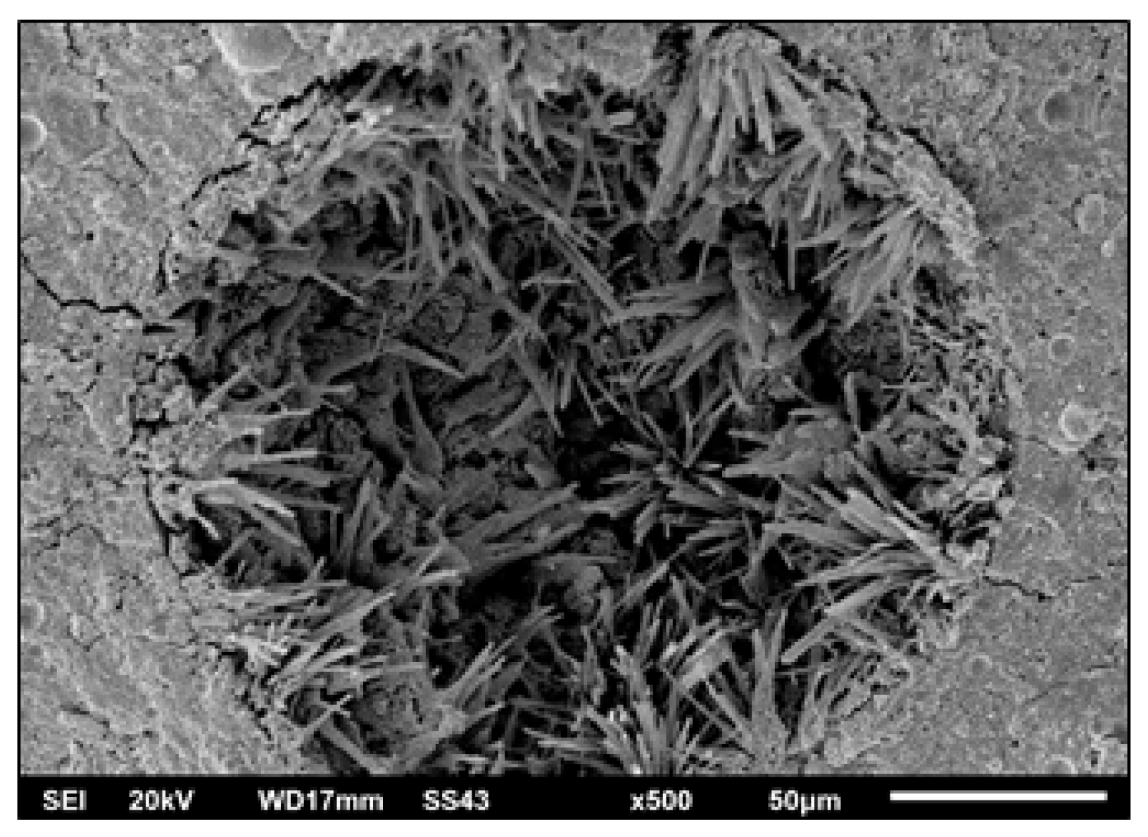
Figure 3 shows the needle-like ettringite crystals (DEF) growing in the capillary pores; the morphology of ettringite demonstrates radial growth and nucleation, resulting in intense cracking of the composites (Figure 4).
The two aforementioned chemical reactions are strongly exothermic [45,46] (ettringite and monosulfate generate 207 cal/g and 120 cal/g, respectively), but, generally, they do not last long and are followed by a period of a few hours of relatively low heat evolution. However, the HFFA used in this study consists of high amounts of SO3; sulfate ions in the form of gypsum demonstrate high reactivity with the compounds of the clinker, leading to (a) high early temperature during mixing (up to 50 °C), (b) long setting time and low strength at early ages due to the absence of C3A (the specimens were demolded after 2 days; Table 3) and (c) delayed ettringite formation (DEF) resulting in low compressive strength for the composite concretes at late ages.
According to Fischer et al. [43], the particle size of all matrix components should be properly graded to achieve self-consolidating fresh properties. Furthermore, a dense microstructure may be achieved through optimization of the particle size distribution of the composite raw materials (cement, mineral admixture (FA) and sand) [43]. The ideal gradation of the ingredient particles to produce dense packing and good workability in the present study was determined using the equation suggested by Fuller and Thomson [44] (Equation (3)), where fd is the fraction of particles smaller than d, d is the particle size smaller than D (mm) and dmax is the maximum particle size (mm).
f d = 100 ( d d m a x )
The grain size distributions of the ingredient particles of each of the seven mixtures tested in this study are compared to the optimum one in Figure 5. From this, it is observed that the mixtures (M-5-15-F) with the finer grain size (<300 μm) HFFA are closer to the ideal gradation suggested by Fuller and Thomson [44].

3.3. Specimen Preparation

The dry raw materials (cement, FA and sand) were first added to the mixer drum and mixed thoroughly for at least 30 min. Then, the water was mixed with the superplasticizer before being slowly added to the dry raw materials in the mixer. Upon reaching self-consolidating fluidity, the mixture was poured into molds without any vibration. The cast specimens were kept in the molds and covered with glass for 24 or 48 h, as recorded in Table 3. They were then cured under water until the day of testing. It is worth noting that the use of HFFA generally resulted in longer setting times and subsequently lower rates of strength development; for this reason, all tests were performed at the ages of 28, 56 and 100 days after specimen casting.

3.4. Testing

Various tests were undertaken to examine both the physical and mechanical properties of the hardened specimens. These included both compression and indirect tension (three-point bending), as well as porosity, bulk density and capillary absorption measurements. All the tests were carried out at various ages (28, 56 and 100 days) in order to study the influence of the addition of FA against time of curing in water.

3.4.1. Uniaxial Compression

Tests for each mix design were carried out on three small prism specimens with an aspect ratio of 2 (Figure 6a), with a displacement loading rate of 1.50 µm/s, using a closed-loop, servo hydraulic-controlled testing machine (Controls—Advantest 9). The prism dimensions were 40 mm × 40 mm × 80 mm. Axial deformations were measured using two linear variable differential transducers (LVDTs) mounted on opposite sides of the specimens, recording the differential displacement of the loading plates. An additional LVDT measured the deformation of the specimen on a third side; based on this, the displacement of the plates was controlled. Due to the small size of the aggregates in the self-compacting HVFA mixtures, this class of material is generally more compliant than normal concrete, attaining its strength at a higher axial compression strain. Strain gauges were also placed on three sides of the specimens for the tests that were performed at the age of 100 days (see Figure 6a). Strain gauges on the two opposite sides (SG1 and SG2) measured vertical strain parallel to the load, while on the third orthogonal side, the strain gauge used (SG3) measured lateral strain. The modulus of elasticity and Poisson’s ratio were calculated using the recordings of these strain gauges.

3.4.2. Three-Point Bending

Three small-sized beams from each mix design, having a 40 mm square cross-section and 160 mm length, were tested in three-point bending. The tests were carried out at a low force rate using a manual testing machine. Geometric details of the test setup and of the specimens are given in Figure 6b. Flexural tests of the type considered here are routinely used to indirectly obtain tensile strength from flexural strength [47,48,49]. Nevertheless, three-point bending generally overestimates the tensile strength, compared to four-point bending and uniaxial tensile tests.

3.4.3. Porosity and Bulk Density

The open porosity and bulk density of cubic specimens with dimensions 50 mm × 50 mm × 50 mm were determined by vacuum saturation [50]. The samples were first dried in an air oven at 105 °C to constant mass. They were then allowed to cool before being placed in a vacuum chamber, which was connected to a vacuum pump. The chamber was evacuated by pumping for at least 2 h, and was then filled with water until the samples were fully covered. Following the immersion of the samples in water, the chamber was returned to atmospheric pressure and the samples were left to soak for at least 24 h. The dry weight (md), the saturated weight (ms) and the weight of the samples immersed in water (mh) were used to calculate the open volume fraction porosity P0 (%) and the bulk density ρb (kg/m3) in accordance with Equations (4) and (5):
P 0 = m s m d m s m h
ρ b = m d m s m h

3.4.4. Capillary Absorption (Sorptivity)

The capillary absorption (sorptivity) of the samples was determined following the direct gravimetric method described in [50]. Cubic specimens with dimensions 50 mm × 50 mm × 50 mm were used in all measurements. The test liquid was ethanol instead of water in order to avoid any water/cement interactions during the measurement. The temperature of the test liquid was continuously monitored during the measurements. The sorptivity S (mm/min½) of the samples was estimated from the slope of an i vs. t½ graph, where i (mm) is the volume of liquid absorbed per unit surface area of the sample and t is the time (min). It is worth noting that the measurements for each group and age were normalized at the temperature of 20 °C.

4. Results

4.1. Porosity and Bulk Density

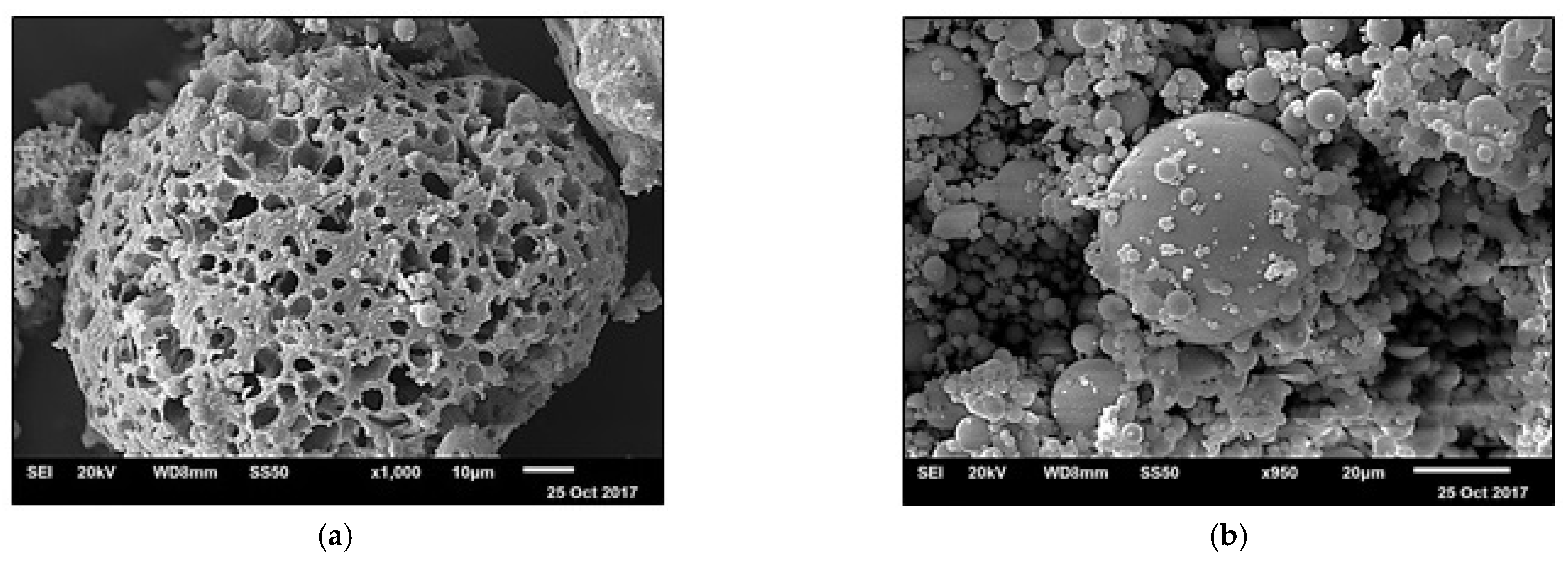
Figure 7 summarizes the open porosity and bulk density results. The values reported comprise the average of measurements on three different specimens. From the results, it is evident that the bulk density of all mix designs generally shows a tendency to increase with time from 28 to 100 days of age, whereas the open porosity follows the opposite trend, as expected. With an increasing amount of HFFA, the bulk density of the hardened composites decreases, whereas their open porosity increases. This is attributed to the fact that mixtures with a higher percentage of HFFA required higher dosages of water in order to obtain the same workability (Table 3), mainly because of the porous nature of the carbon particles included in the HFFA (Figure 8a). In contrast, Class F FA includes significant amounts of cenospheres (Figure 8b), which improve the workability of the fresh mixture. The presence of silicates in Class F FA (see also Figure 1) also enhances the water retentivity, and consequently the pumping properties, of the fresh mixture. As a result, when used with a recommended superplasticizer, Class F FA leads to a cementitious composite (e.g., PM) with reduced water demand and excellent workability (see Table 4 for the characteristics of PM in the fresh state). On the other hand, the mixture prepared without the HFFA additive has a similar porosity (ca. 30%) to the rest of the mixtures, except for M-15-F. The results are generally in line with those of other studies [51,52].
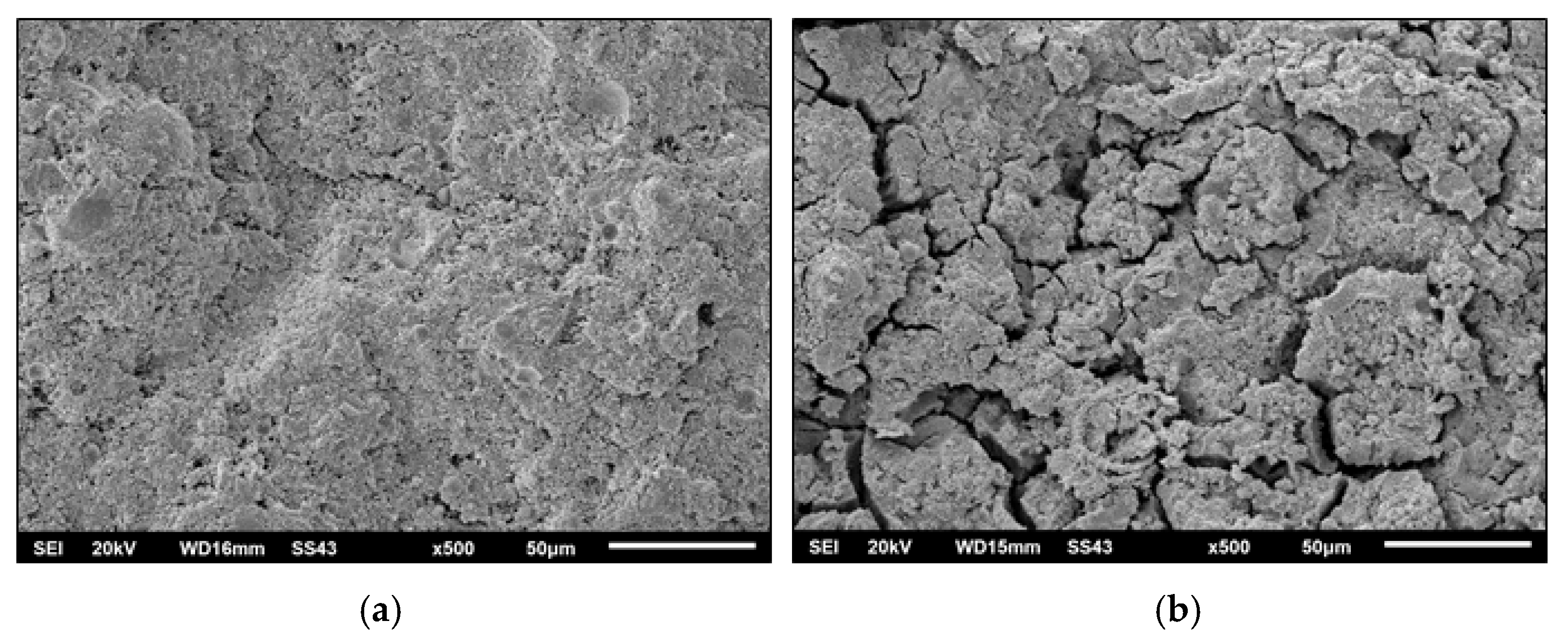
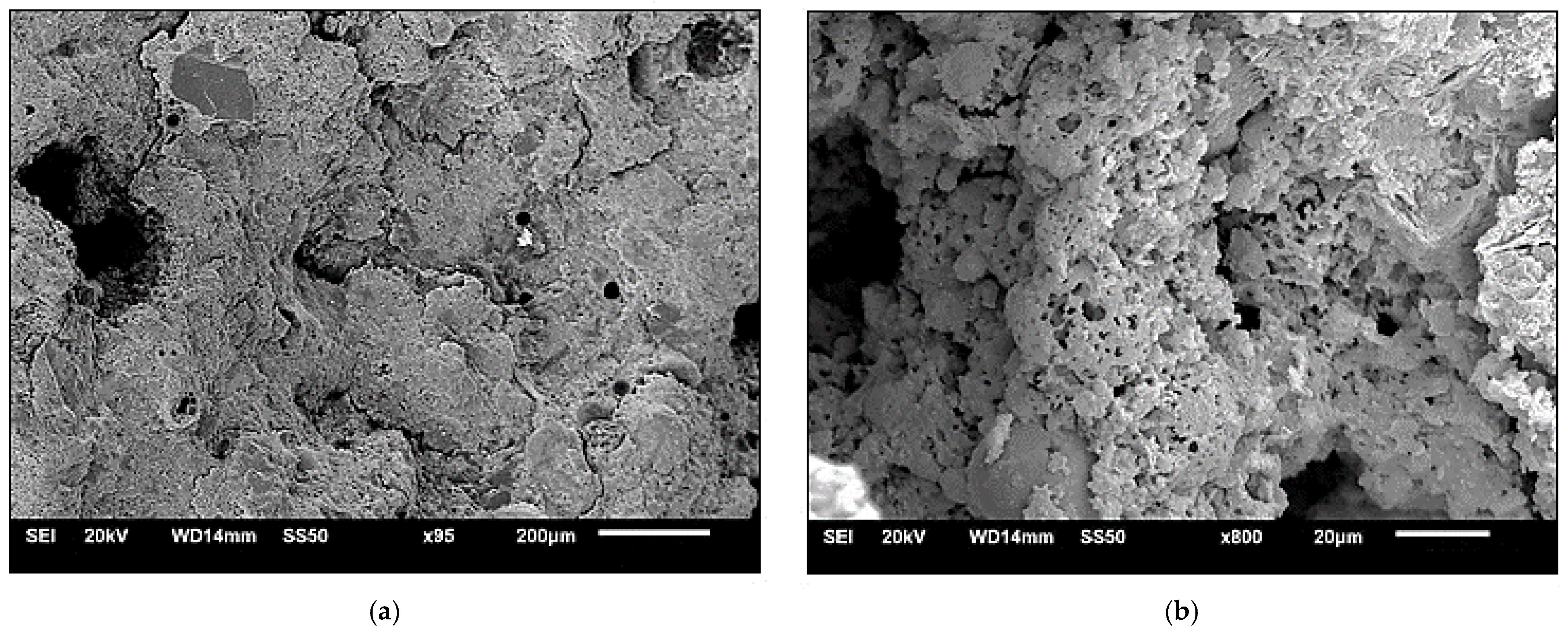
Although the percentage of HFFA replacing Class F FA clearly affects the bulk density and open porosity of the hardened composites, its grain size distribution does not seem to have any significant effect on the aforementioned properties, except for the mixtures with 15% w/w replacement of cement and Class F FA with HFFA (Figure 7). In the latter, higher open porosities and lower bulk densities have been observed, at all three testing ages, when fine (d < 300 μm) HFFA was used. This suggests that the grain size distribution of HFFA may affect the durability of the cementitious composites investigated at quantities >10% of the combined cement and FA weight. Having said this, the reduced bulk density and increased (>35%) open porosity of mixture M-15-F may also be attributed to the much higher water content of this sample and the heat generated during its production (see Table 3), which negatively affected its microstructure (Figure 9a). At the same time, the sample without the HFFA additive exhibits a dense structure, without crack formation at late ages (see Figure 4).
Figure 10 confirms the inverse linear relationship between the bulk density and the open porosity of the investigated composites. Using an estimate of the solid density (ρs), based on the composition of the materials under study, and the experimental bulk densities, one may also calculate the total porosities (f):
f = ρ s ρ b ρ s ,
From Figure 10, it is clear that the measured open porosity (dotted line) is close to the total porosity (solid line) estimated from experimental bulk densities, with the highest variation (8%) in the case of sample M-5-C, which has the lowest open porosity. This suggests that the closed porosity of the composites under study decreases with increasing total porosity, as expected.

4.2. Capillary Absorption (Sorptivity)

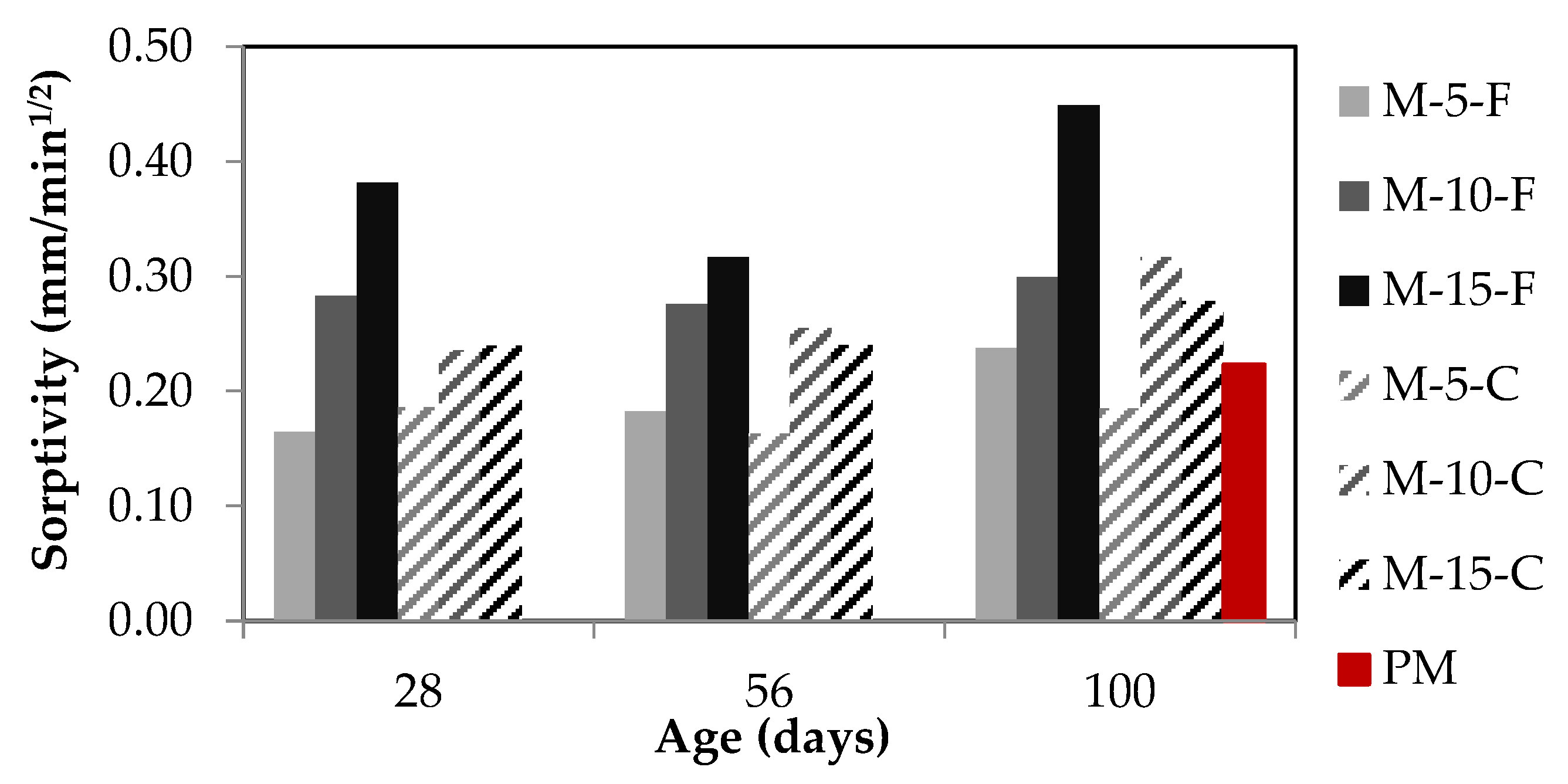
Figure 11 shows the normalized capillary absorption (sorptivity) results over time for all samples studied. The values reported again comprise the average of measurements on three different specimens. From these results, it appears that the sorptivity does not vary significantly with time, despite the fact that a general increase in value is observed from 28 to 100 days of testing. This suggests that the early development of the microstructure of cementitious composites is crucial in their overall durability behavior. However, the sorptivity seems to be affected negatively by the percentage of HFFA replacing Class F FA; this is more obvious in the samples with the fine-grained HFFA (M-5-15-F). Furthermore, the use of fine-grained (d < 300 μm) HFFA also leads to generally higher sorptivity. Sample PM has lower sorptivity at late ages, compared to the other mixtures, except for M-5-C; this is associated with the late pozzolanic activity of the additives (F-class FA and HFFA) when these are used in low amounts. In general, 5% w/w HFFA (M-5-C and M-5-F) addition resulted in relatively low capillary absorption at all ages. This is attributed to the formation of ettringite in the pores (see also Figure 3) of the composite, which likely prevented the ingress of ethanol. The increase in capillary absorption with age may, in turn, be attributed to internal sulfate attack, which leads to expansion and cracking of the composite mortars [53,54,55].
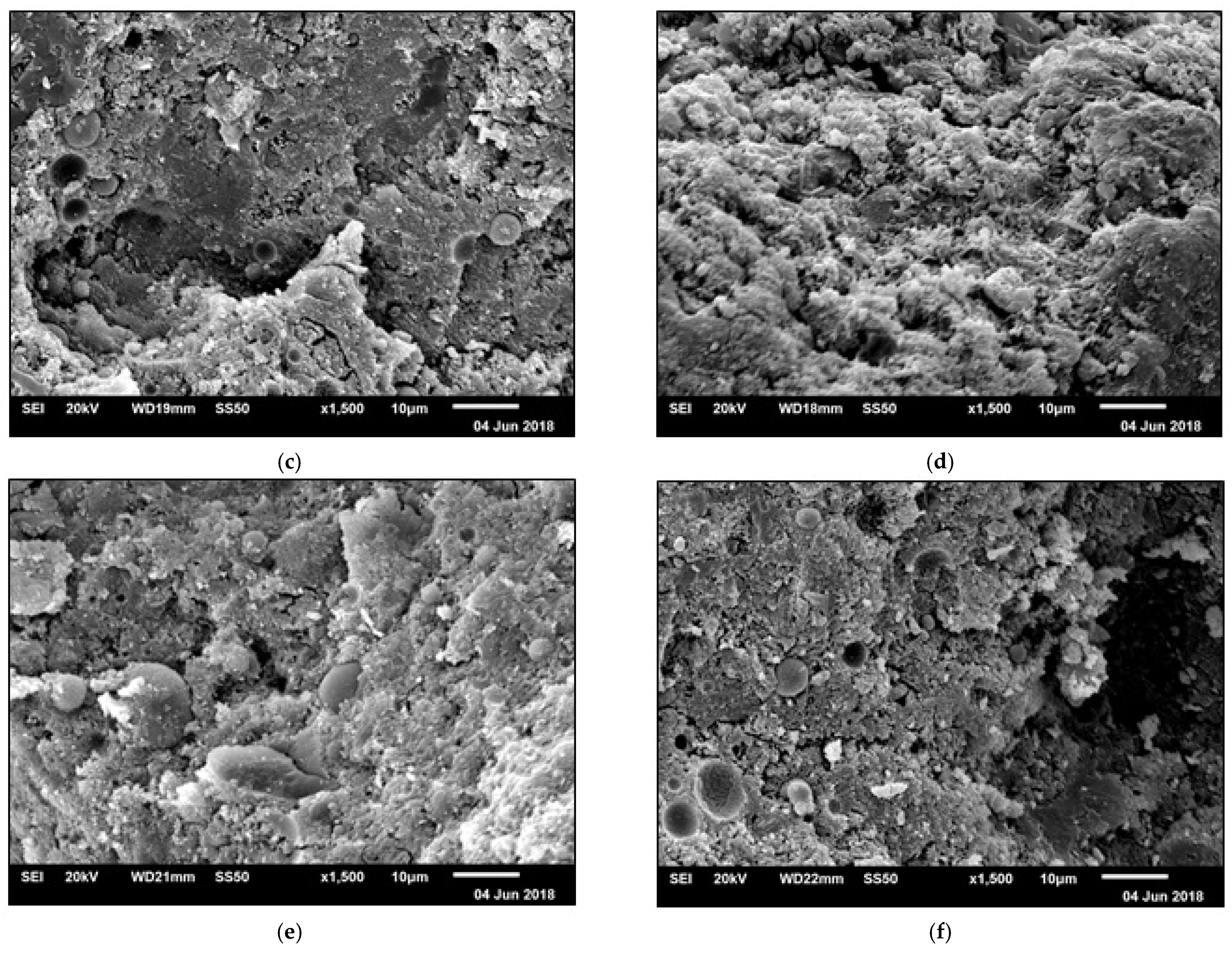
Sicakova et al. [56] investigated the water absorption of composite building materials containing fine-grained additives. These authors suggested that the fine particle size has an adverse effect on the sorptivity of both mortars and concretes, while the higher content of fine-grained material further increases the sorptivity coefficient. Fetter [57] estimated the capillary rise in sedimentary rocks with various grain fineness, showing that fine-grained rocks demonstrate higher capillary absorption than coarse-grained rocks. These findings are in line with the results reported in our study, whereby the sorptivity appears to increase with the use and percentage content of fine-grained HFFA. The higher sorptivity of the samples with the fine-grained HFFA is attributed to their microstructure (Figure 12). Samples with fine-grained HFFA have a rough and sugary texture due to the weak bonding of their grains. In contrast, samples with coarse-grained HFFA are more consistent. Furthermore, the higher the percentage content of HFFA, the more porous the microstructure of the samples studied (Figure 12).

4.3. Three-Point Bending and Uniaxial Compression

The mean flexural strength, fct,fl, obtained from the various tests carried out at different curing ages is plotted in Figure 13 (bottom). The values used in this figure were obtained following the modulus of rupture expression defined in ASTM C293 [58]:
f c t , f l = 3 P L 2 b d 2
In Equation (7), P is the maximum measured applied load (in N), L is the span length (distance between the supports, in mm), b is the width and d is the depth of the cross-section of the specimen (in mm).
From the results reported in Figure 13 (bottom), it appears that the average ultimate flexural strength after 100 days of curing varied from 8.25 to 12.5 MPa. This is in all cases significantly higher than the respective value reported for the reference mixture (PM). The improvement in flexural strength with FA addition is in line with results reported elsewhere [59,60] and is attributed to the fact that FA changes the matrix chemical composition. The compressive strength (fc) for all samples investigated is also plotted in Figure 13 (top). The values reported at each curing age were calculated as the average of the maximum load sustained by the three specimens tested divided by their cross-sectional area.
The highest compressive strength was obtained for the specimens with the lowest percentage replacement of Class F FA with HFFA (M-5-F/C). This is in line with the porosity/density results reported earlier and it is attributed to the fact that Class F FA contains significant amounts of silicates (Figure 1 and Figure 8), which induce improved internal cohesion to the composites, thus increasing their ultimate strength. In contrast, the porous nature of HFFA (Figure 8) leads to increased demands for water and hence lower compressive strengths. The reference mix design (PM) reached a uniaxial compressive strength of 50 MPa after 100 days of curing. This is generally lower than the strengths recorded for the rest of the mix designs, with the exception of M-15-F. In fact, the latter seems to be the only studied mix design affected negatively in terms of compressive strength by the grain size distribution of the HFFA. It is worth noting that, despite the differences in compressive strength noted, the Poisson’s ratio showed no significant alteration with the variation in the HFFA content and/or grain size distribution; the average value calculated by the recordings of the laterally and axially placed strain gauges on all composites was 0.2.

5. Discussion

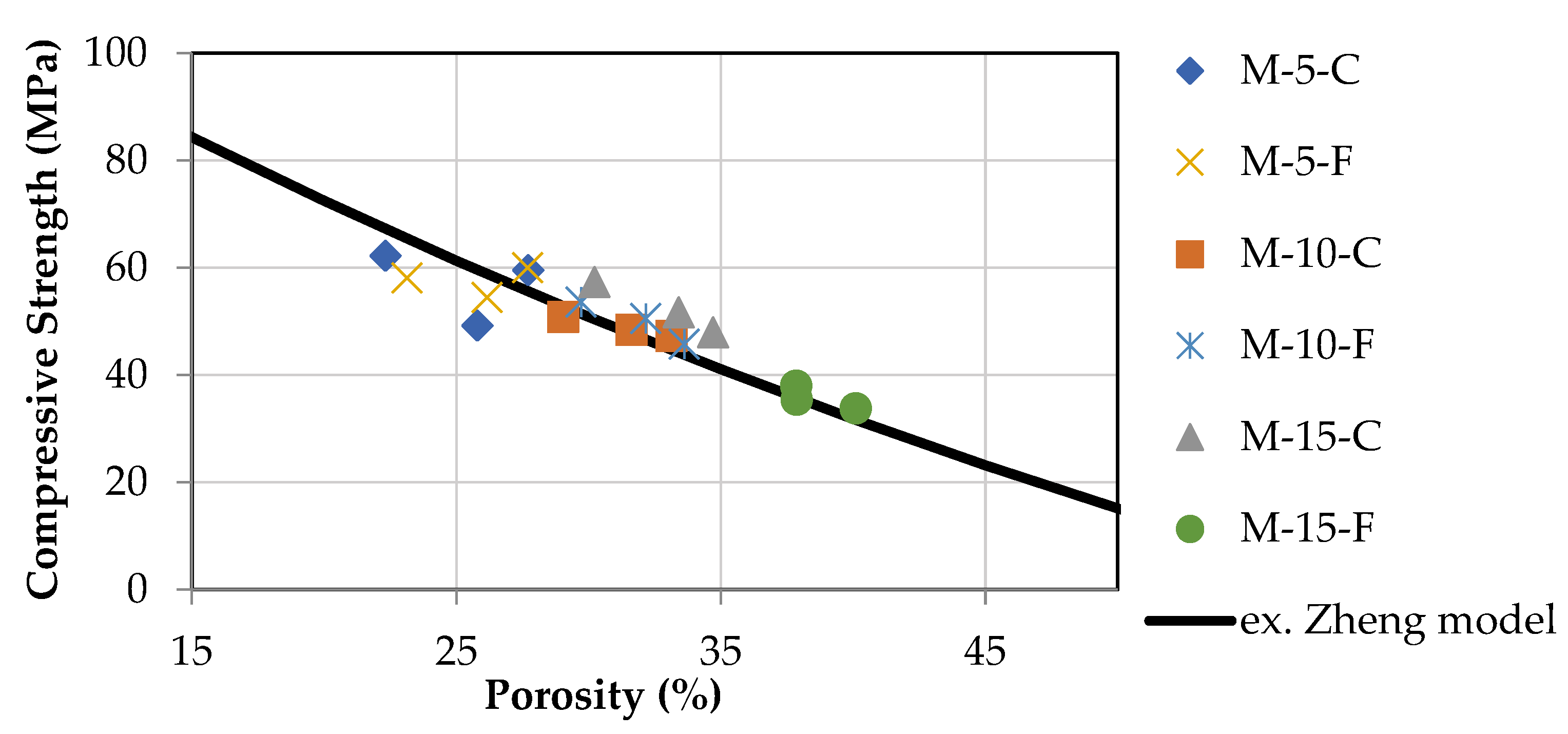
In Figure 14, the mean compressive strength from each mixture is plotted against the open porosity. The symbols refer to the experimental data, while the solid line is the extended Zheng model proposed by Chen et al. [61]. The theoretical relation between strength and porosity is given by a simple formula with only two parameters that define the strength characteristics of cement mortar, i.e., the compressive strength of the pore-free material (σo) and the percolation porosity at failure (pc).
σ = σ ο p c p p c 1.85 · 1 p 2 / 3 1 / 2
The results compare well with the model proposed by Chen et al. [61] if the constants σo and pc take values of 130 MPa and 0.6, respectively.
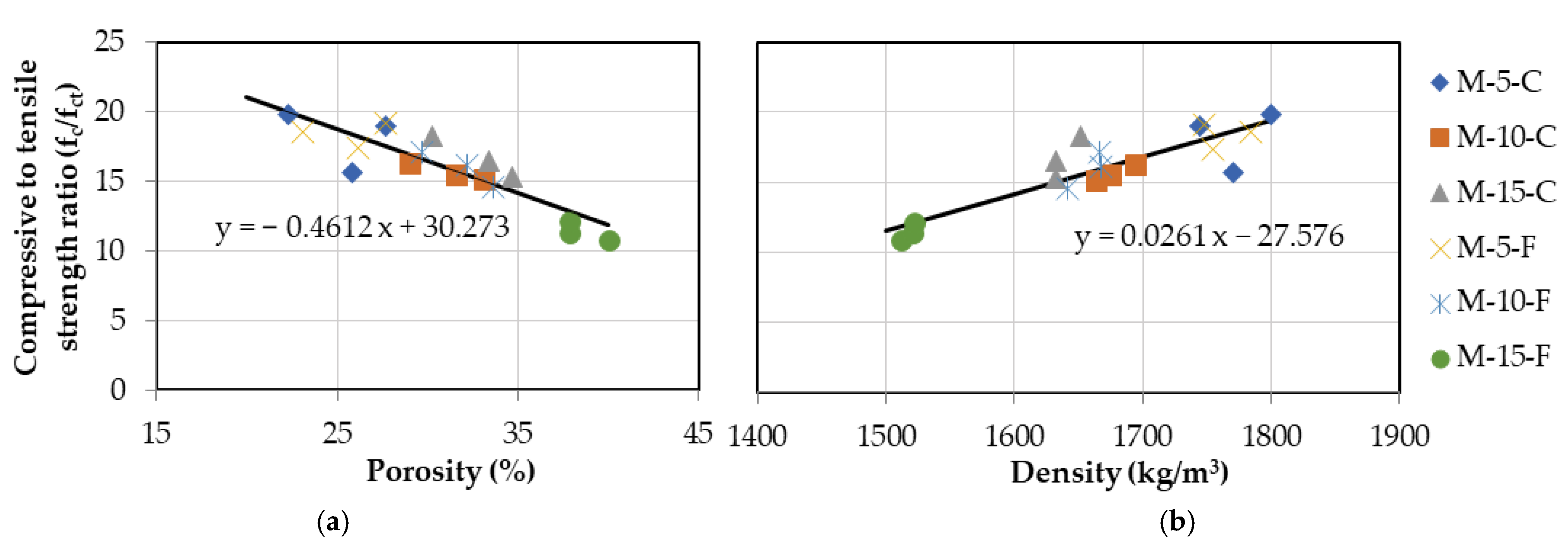
Values of the uniaxial tensile strength derived based on Equation (7) were used to estimate the compressive to tensile strength ratio fc/ft,cr used in Figure 15a,b.
f t , c r = A f l f c t , f l ,   where   A f l = a f l h b 0.7 1 + a f l h b 0.7 = 0.6 ,   a f l = 0.06
In Equation (9), hb is the cross-sectional depth of the flexural specimen in mm, fct,fl is the mean flexural tensile strength in MPa and Afl is a coefficient that takes into consideration the size of the specimen and its brittleness.
Comparing the compressive to tensile strength ratio to the open porosity and bulk density of the mixtures under investigation (Figure 15a,b, respectively) gives a linear relationship, with the ratio decreasing with increasing porosity and increasing with increasing density, as expected. This linear relation is in agreement with previous experimental research [62]. The ratio of compressive to tensile strength estimated here seems to take values greater than those for normal concrete (fc/ft,cr ≈ 10), mainly due to the self-compacting properties of the mixtures tested that generally lead to a denser microstructure and increased compressive strength.
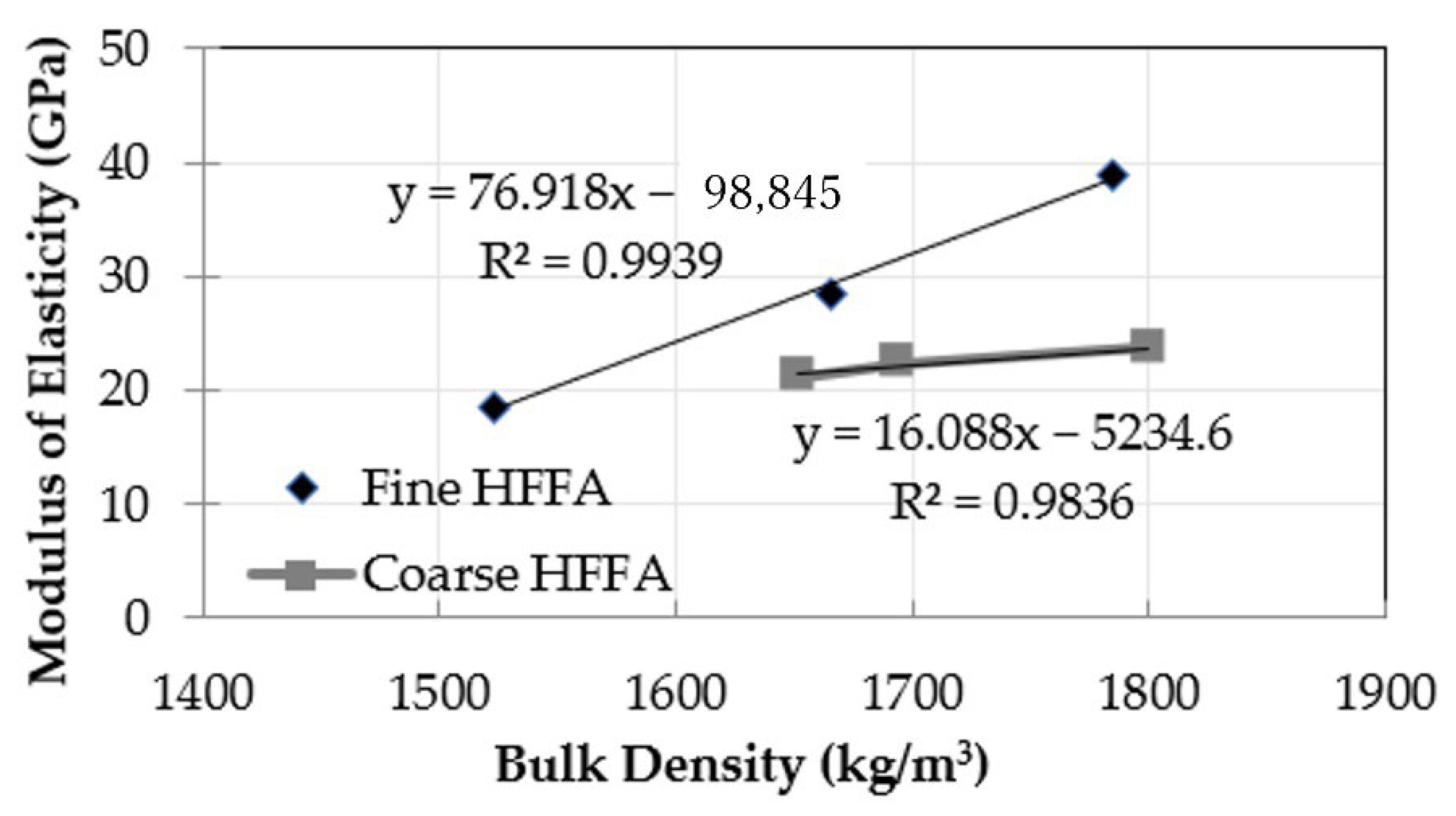
Finally, in Figure 16, the modulus of elasticity of all composites after 100 days of curing is plotted against their bulk densities. The results indicate that the modulus of elasticity increases with the bulk density of the hardened composite, irrespective of the grain size distribution of HFFA. Nevertheless, this increase is more profound in the case of the finer HFFA (d < 300 μm); this is in line with the compressive/flexural strength results (Figure 13). The lowest modulus of elasticity has been recorded for sample M-15-F; this is the sample with the lowest bulk density and highest porosity (Figure 7), which has shown intense cracking under SEM (Figure 9 and Figure 12).

6. Conclusions

Characterization of the performance of a new type of high-volume fly ash (HVFA) self-compacting cementitious composite, produced with the use of heavy fuel fly ash (HFFA), as a replacement of Class F Fly Ash, is presented in this paper. In an effort to investigate the effect of this by-product on laboratory-produced cementitious composites, we adopted a series of tests, including sieve and XRD analyses of the raw materials, physico-mechanical testing at various ages, and microscopic observation under SEM of the hardened composites comprising varying percentages (5–15% w/w of cement and Class F FA) and grain size distributions of locally obtained previously unused HFFA.
The results have shown that both the mechanical and physical properties of the studied composites generally deteriorate with increasing use of HFFA. Nevertheless, HFFA may still be used as a cement and Class F FA replacement at quantities ≤10% w/w. In fact, depending on the quantity and grain size distribution of the HFFA, this may even improve the mechanical properties of the hardened composite in the long term, provided that a careful mix design is adopted.
Further experimental work on HFFA (including an investigation of its effect on the durability characteristics of the end-product composites and confirmation of the non-leaching of heavy metals) may lead to the introduction of this industrial by-product in design codes, and therefore in engineered construction. Code provisions currently refer to cracking tensile properties and are calibrated for normal-weight concrete with coarse aggregates and no FA. Therefore, this paper may lay the foundation for future work on the effect of HFFA on cementitious composites in an effort to introduce its use in design codes.

Author Contributions

Conceptualization, A.G., I.I. and N.C.; Methodology, A.G., I.I. and N.C.; Writing—original draft preparation, A.G. and N.C.; Writing—review and editing, A.G. and I.I.; Supervision, I.I. All authors have read and agreed to the published version of the manuscript.

Funding

This research received no external funding.

Data Availability Statement

Not applicable.

Conflicts of Interest

The authors declare no conflict of interest.

References

  1. Rubenstein, M. Emissions from the Cement Industry. 2012. Available online: https://news.climate.columbia.edu/2012/05/09/emissions-from-the-cement-industry/ (accessed on 8 November 2022).
  2. Li, G.; Zhou, C.; Ahmad, W.; Usanova, K.I.; Karelina, M.; Mohamed, A.M.; Khallaf, R. Fly Ash Application as Supplementary Cementitious Material: A Review. Materials 2022, 15, 2664. [Google Scholar] [CrossRef] [PubMed]
  3. Onyelowe, K.C.; Kontoni, D.-P.N.; Ebid, A.M.; Dabbaghi, F.; Soleymani, A.; Jahangir, H.; Nehdi, M.L. Multi-Objective Optimization of Sustainable Concrete Containing Fly Ash Based on Environmental and Mechanical Considerations. Buildings 2022, 12, 948. [Google Scholar] [CrossRef]
  4. ACI Committee 232. Use of Fly Ash in Concrete; American Concrete Institute: Farmington Hills, MI, USA, 2003. [Google Scholar]
  5. Kagadgar, S.A.; Saha, S.; Rajasekaran, C. Mechanical and Durability Properties of Fly Ash Based Concrete Exposed to Marine Environment. Sel. Sci. Pap.-J. Civ. Eng. 2017, 12, 7–18. [Google Scholar] [CrossRef] [Green Version]
  6. Moffatt, E.G.; Thomas, M.D.; Fahim, A. Performance of high-volume fly ash concrete in marine environment. Cem. Concr. Res. 2017, 102, 127–135. [Google Scholar] [CrossRef]
  7. Mehta, P.K.; Monteiro, P.J.M. Concrete: Microstructure, Properties, and Materials; McGraw-Hill Education: New York, NY, USA, 2014. [Google Scholar]
  8. Badar, S.; Kupwade-Patil, K.; Bernal, S.A.; Provis, J.; Allouche, E.N. Corrosion of steel bars induced by accelerated carbonation in low and high calcium fly ash geopolymer concretes. Constr. Build. Mater. 2014, 61, 79–89. [Google Scholar] [CrossRef]
  9. Dave, N.; Misra, A.K.; Srivastava, A.; Kaushik, S.K. Setting time and standard consistency of quaternary binders: The influence of cementitious material addition and mixing. Int. J. Sustain. Built Environ. 2017, 6, 30–36. [Google Scholar] [CrossRef] [Green Version]
  10. Kearsley, E.P.; Wainwright, P.J. The Effect of Fly Ash Properties on Concrete Strength. J. South Afr. Inst. Civ. Eng. 2003, 45, 19–24. [Google Scholar]
  11. Chousidis, N.; Rakanta, E.; Ioannou, I.; Batis, G. Mechanical properties and durability performance of reinforced concrete containing fly ash. Constr. Build. Mater. 2015, 101, 810–817. [Google Scholar] [CrossRef]
  12. Chousidis, N.; Ioannou, I.; Rakanta, E.; Koutsodontis, C.; Batis, G. Effect of fly ash chemical composition on the reinforcement corrosion, thermal diffusion and strength of blended cement concretes. Constr. Build. Mater. 2016, 126, 86–97. [Google Scholar] [CrossRef]
  13. American Coal Ash Association. Fly Ash Facts for Highway Engineers. J. Chem. Inf. Model. 2013, 53, 1689–1699. [Google Scholar] [CrossRef]
  14. Thomas, M.D.A.; Fournier, B.; Folliard, K.J. Alkali-Aggregate Reactivity (AAR) Facts Book; United States Federal Highway Administration; Office of Pavement Technology: Washington, DC, USA, 2013. [Google Scholar]
  15. Concrete Society. The Use of GGBS and PFA in Concrete; Technical Report No. 40; Slough (UK); The Concrete Society Press: Wexham, UK, 1991. [Google Scholar]
  16. Barrow, R.S.; Hadchiti, K.M.; Carrasquillo, P.M.; Carrasquillo, R.L. Temperature Rise and Durability of Concrete Containing Fly Ash. In Third International Conference on the Use of Fly Ash, Silica Fume, Slag and Natural Pozzolans in Concrete; Malhotra, V.M., Ed.; ACI SP-114; American Concrete Institute: Detroit, MI, USA, 1989; Volume 2, pp. 331–347. [Google Scholar]
  17. Anon, A. Investigation of the Pozzolanic Nature of Coal Ashes. Eng. News 1914, 71, 1334–1335. [Google Scholar]
  18. Davis, R.E.; Carlson, R.W.; Kelly, J.W.; Davis, H.E. Properties of Cements and Concretes Containing Fly Ash. J. Am. Concr. Institude 1937, 33, 577–611. [Google Scholar]
  19. Halstead, W.J. Use of Fly Ash in Concrete; Transportation Research Board, National Research Council: Washington, DC, USA, 1986; Volume 127. [Google Scholar]
  20. Timms, A.G.; Grieb, W.E. Use of Fly Ash in Concrete; American Society for Testing and Materials: Washington, DC, USA, 1956; pp. 1139–1160. [Google Scholar]
  21. Brink, R.H.; Halstead, W.J. Studies Relating to the Testing of Fly Ash for Use in Concrete; American Society for Testing and Materials: Washington, DC, USA, 1956; Volume 56, pp. 1161–1214. [Google Scholar]
  22. Malhotra, V.M. Superplasticized Fly Ash Concrete for Structural Applications. Concr. Int. 1986, 8, 28–31. [Google Scholar]
  23. Bilodeau, A.; Malhotra, V.M. High-Volume Fly Ash System: Concrete Solution for Sustainable Development. ACI Mater. J. 2000, 97, 41–48. [Google Scholar]
  24. Mehta, P.K. High-Performance, High-Volume Fly Ash Concrete for Sustainable Development. In Proceedings of the International Workshop on Sustainable Development and Concrete Technology, Beijing, China, 20–21 May 2004; pp. 3–14. [Google Scholar]
  25. Malhotra, V.M.; Mehta, P.K. High-Performance, High-Volume Fly Ash Concrete. Concr. Int. 2002, 24, 30–34. [Google Scholar]
  26. National Research Council of the National Academies. Managing Coal Combustion Residues in Mines; Committee on Mine Placement of Coal Combustion Wastes; National Academies Press: Washington, DC, USA, 2006. [Google Scholar]
  27. U.S. Environmental Protection Agency, Office of Solid Waste. Human and Ecological Risk Assessment of Coal Combustion Wastes. 2007. Available online: https://grist.org/wp-content/uploads/2011/02/epa-coal-combustion-waste-risk-assessment.pdf (accessed on 5 May 2022).
  28. Vitolo, S.; Seggiani, M.; Filippi, S.; Brocchini, C. Recovery of vanadium from heavy oil and Orimulsion fly ashes. Hydrometallurgy 2000, 57, 141–149. [Google Scholar] [CrossRef]
  29. Al-Degs, Y.S.; Ghrir, A.; Khoury, H.; Walker, G.M.; Sunjuk, M.; Al-Ghouti, M.A. Characterization and utilization of fly ash of heavy fuel oil generated in power stations. Fuel Process. Technol. 2014, 123, 41–46. [Google Scholar] [CrossRef]
  30. Al-Osta, M.A.; Baig, M.G.; Al-Malack, M.H.; Al-Amoudi, O.S.B. Study of heavy fuel oil fly ash for use in concrete blocks and asphalt concrete mixes. Adv. Concr. Constr. 2016, 4, 123–143. [Google Scholar] [CrossRef]
  31. Camilleri, J.; Anastasi, M.; Torpiano, A. The microstructure and physical properties of heavy oil fuel ash replaced Portland cement for use in flowable fill concrete and the production of concrete masonry units. Constr. Build. Mater. 2013, 38, 970–979. [Google Scholar] [CrossRef]
  32. Desjardins, J. Europe’s Electricity Production by Country and Fuel Type. Available online: http://www.visualcapitalist.com/europes-electricity-production-by-country-and-fuel-type (accessed on 10 May 2022).
  33. Al-Malack, M.; Bukhari, A.; Al-Amoudi, O.; Al-Muhanna, H.; Zaidi, T. Characteristics of Fly ash Produced at Power and Water Desalination Plants Firing Fuel Oil. Int. J. Environ. Res. 2013, 7, 455–466. [Google Scholar] [CrossRef]
  34. Hassan, M.I.H.; Kadir, A.A.; Mohd Kamil, N.A.F.; Hashar, N.N.H.; Sarani, N.A.; Ibrahim, B.; Salleh, K.M.; Abdullah, M.M.A.B. Mechanical properties and toxicity characteristics of petroleum sludge incorporated with palm oil fuel ash and quarry dust in solidification/stabilization matrices. Arch. Metall. Mater. 2022, 67, 1259–1266. [Google Scholar]
  35. Chen, Q.; Tyrer, M.; Hills, C.; Yang, X.; Carey, P. Immobilisation of heavy metal in cement-based solidification/stabilisation: A review. Waste Manag. 2009, 29, 390–403. [Google Scholar] [CrossRef] [PubMed]
  36. Daous, M. Utilization of Cement Kiln Dust and Fly Ash in Cement Blends in Saudi Arabia. J. King Abdulaziz Univ. Eng. Sci. 2004, 15, 33–45. [Google Scholar] [CrossRef] [Green Version]
  37. Rybowicz, P.; Mochnaczewski, M.; Kozieł, M.; Uruski, L.; Łagosz, A.; Michalik, M.; Chmielarz, L.; Adamski, A. Key Parameters of Fly Ashes Generated from the Industrial Energy Sector Decisive for Their Pro-ecological Applications. Energy Fuels 2020, 34, 6229–6238. [Google Scholar] [CrossRef]
  38. Basha, S.I.; Aziz, A.; Maslehuddin, M.; Ahmad, S.; Hakeem, A.S.; Rahman, M.M. Characterization, Processing, and Application of Heavy Fuel Oil Ash, an Industrial Waste Material—A Review. Chem. Rec. 2020, 20, 1568–1595. [Google Scholar] [CrossRef]
  39. Al-Slaty, F.; Al-Dabsheh, I.; Odeh, T. Characteristics of Residual Oil Fly Ash and Their Utility for Construction Purposes. Kuwait J. Sci. 2019, 46, 83–89. [Google Scholar]
  40. Alshaaer, M.; Fahmy, T.; Shqair, M.; Al-Kafawein, J. Production of Heavy Fuel Oil Fly Ash (HFO)-Based Geopolymers for Passive Cooling Systems. Int. J. Appl. Eng. Res. 2018, 13, 134–140. [Google Scholar]
  41. Evagorou, K.; Dimitriou, A.; Tsamatsoulis, D. Technical Mathematical Relations of Concrete Compressive Strength to Cement. In Proceedings of the 15th Concrete Conference, Alexandroupoli, Greece, 25–27 October 2006; pp. 25–27. [Google Scholar]
  42. Georgiou, A.V.; Pantazopoulou, S.J. Effect of fiber length and surface characteristics on the mechanical properties of cementitious composites. Constr. Build. Mater. 2016, 125, 1216–1228. [Google Scholar] [CrossRef]
  43. Fischer, G.; Wang, S.; Li, V.C. Design of Engineered Cementitious Composites (ECC) for Processing and Workability Re-quirements. In Brittle Matrix Composites 7; Woodhead Publishing: Sawston, UK, 2003. [Google Scholar]
  44. Fuller, W.B.; Thompson, S.E. The Laws of Proportioning Concrete. Trans. Am. Soc. Civ. Eng. 1907, 59, 67–143. [Google Scholar] [CrossRef]
  45. Hanehara, S.; Oyamada, T. Reproduction of Delayed Ettringite Formation (DEF) in concrete And Relationship between DEF and Alkali Silica Reaction; Korea Concrete Institute: Seoul, Korea, 2010; pp. 1024–1029. [Google Scholar]
  46. Ingham, J.P. Concrete. In Geomaterials Under the Microscope; Ingham, J.P., Ed.; Academic Press: Boston, MA, USA, 2013; pp. 75–120. [Google Scholar]
  47. Mindess, S.; Young, J.F.; Darwin, D. Concrete. Pearson Education; Prentice-Hall: Upper Saddle River, NJ, USA, 2003. [Google Scholar]
  48. Kosmatka, S.H.; Kerkhoff, B.; Panarese., W.C. Design and Control of Concrete Mixtures; Portland Cement Association: Skokie, IL, USA, 2002. [Google Scholar]
  49. FIB Model Code. Model Code 2010; Federation Internationale du Beton (fib). 2010. Available online: https://www.fib-international.org/publications/fib-bulletins/model-code-2010-first-complete-draft-vol-2-book-144-detail.html (accessed on 8 July 2022).
  50. Hall, C.; Hoff, W.D. Water Transport in Brick, Stone and Concrete; CRC Press: Boca Raton, FL, USA, 2021. [Google Scholar]
  51. Nath, P.; Sarker, P. Effect of Fly Ash on the Durability Properties of High Strength Concrete. Procedia Eng. 2011, 14, 1149–1156. [Google Scholar] [CrossRef] [Green Version]
  52. Saha, A.K. Effect of class F fly ash on the durability properties of concrete. Sustain. Environ. Res. 2018, 28, 25–31. [Google Scholar] [CrossRef]
  53. Thiebaut, Y.; Multon, S.; Sellier, A.; Lacarrière, L.; Boutillon, L.; Belili, D.; Linger, L.; Cussigh, F.; Hadji, S. Effects of stress on concrete expansion due to delayed ettringite formation. Constr. Build. Mater. 2018, 183, 626–641. [Google Scholar] [CrossRef]
  54. Diamond, S. Delayed ettringite formation—Processes and problems. Cem. Concr. Compos. 1996, 18, 205–215. [Google Scholar] [CrossRef]
  55. Mehta, P. Mechanism of expansion associated with ettringite formation. Cem. Concr. Res. 1973, 3, 1–6. [Google Scholar] [CrossRef]
  56. Sicakova, A.; Draganovska, M.; Kovac, M. Water Absorption Coefficient as a Performance Characteristic of Building Mixes Containing Fine Particles of Selected Recycled Materials. Procedia Eng. 2017, 180, 1256–1265. [Google Scholar] [CrossRef]
  57. Fetter, C.W. Applied Hydrogeology, 3rd ed.; Macmillan College Publishing: New York, NY, USA, 1994. [Google Scholar]
  58. ASTM C293; Standard Test Method for Flexural Strength of Concrete (Using Simple Beam with Center-Point Loading). ASTM International: West Conshohocken, PA, USA, 2010. [CrossRef]
  59. Kosior-Kazberuk, M.; Lelusz, M. Strength development of concrete with fly ash addition. J. Civ. Eng. Manag. 2007, 13, 115–122. [Google Scholar] [CrossRef]
  60. Upadhyay, R.; Srivastava, V.; Herbert, A.; Mehta, P.K. Effect of Fly Ash on Flexural Strength of Portland Pozzolona Cement Concrete. J. Acad. Ind. Res. 2014, 3, 218–220. [Google Scholar]
  61. Chen, X.; Wu, S.; Zhou, J. Influence of porosity on compressive and tensile strength of cement mortar. Constr. Build. Mater. 2013, 40, 869–874. [Google Scholar] [CrossRef]
  62. Rossler, M.; Odler, I. Investigations on the Relationship between Porosity, Structure and Strength of Hydrated Portland-Cement Pastes I. Effect of Porosity. Cem. Concr. Res. 1985, 15, 320–330. [Google Scholar]
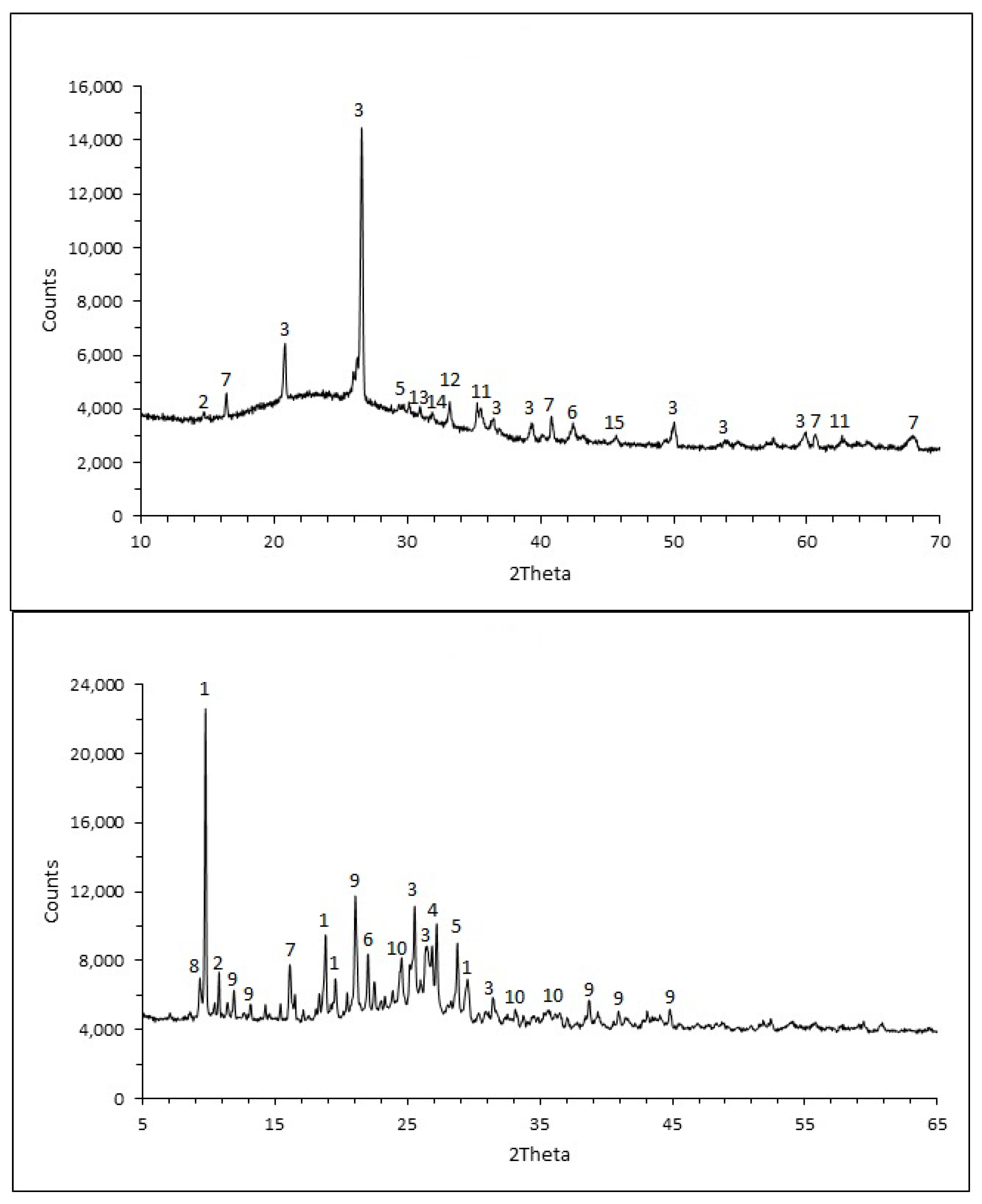
Figure 1. XRD patterns for Class F FA (top) and HFFA (bottom):(1) Anthracene, (2) Carbon, (3) Quartz, (4) Anglesite, (5) Calcite, (6) Goethite, (7) Mullite, (8) Ettringite, (9) Sulfur, (10) Barite, (11) Magnetite, (12) Hematite, (13) Maghemite, (14) Periclase, (15) Alumina.
Constrmater 02 00018 g001
Figure 2. Sieve analysis results for all dry raw materials used in the study.
Constrmater 02 00018 g002
Figure 3. Delayed ettringite formation into the pores of mortars.
Constrmater 02 00018 g003
Figure 4. SEM images for sample M-15-F (b) and PM (a). Intense cracking in the composite mortar is observed, while the sample without the HFFA additive exhibits a dense structure with no cracks or voids.
Constrmater 02 00018 g004
Figure 5. Grain size distributions for the various mixtures and optimal grain size distribution curves: (a) mixtures with HFFA with d < 300 μm; (b) mixtures with HFFA with 300 μm < d < 1 mm.
Constrmater 02 00018 g005
Figure 6. Mechanical tests: (a) dimensions and setup of uniaxial compression test coupon; (b) test setup for three-point bending.
Constrmater 02 00018 g006
Figure 7. (a) Open porosity; (b) bulk density.
Constrmater 02 00018 g007
Figure 8. SEM images showing: (a) porous carbon particles in HFFA and (b) cenospheres in Class F FA; corresponding EDX analyses confirming the composition of the carbon particles (c) and of the cenospheres (d).
Constrmater 02 00018 g008aConstrmater 02 00018 g008b
Figure 9. SEM images for sample M-15-F showing (a) intense cracking; (b) increased porosity. The image on the right also shows evidence of a reaction between the porous carbon particles and the cement paste.
Constrmater 02 00018 g009
Figure 10. Bulk density vs. porosity. The symbols with the dotted line refer to the experimental open porosity data; the solid line has been predicted using an estimate of the solid density.
Constrmater 02 00018 g010
Figure 11. Capillary absorption results.
Constrmater 02 00018 g011
Figure 12. SEM images of composites with different quantities of coarse-grained (left) and fine-grained (right) HFFA: (a + b) 5% w/w; (c + d) 10% w/w and (e + f) 15% w/w HFFA addition.
Constrmater 02 00018 g012aConstrmater 02 00018 g012b
Figure 13. Compressive (top) and flexural (bottom) strength for all mixes.
Constrmater 02 00018 g013
Figure 14. Compressive strength vs. open porosity. The experimental results are compared with the extended Zheng model proposed in [61].
Constrmater 02 00018 g014
Figure 15. Compressive/tensile strength ratio versus: (a) open porosity and (b) bulk density.
Constrmater 02 00018 g015
Figure 16. Modulus of elasticity vs. bulk density.
Constrmater 02 00018 g016
Table 1. Grain size distribution of silica sand.
Sieve (mm)<0.0630.063–0.10.1–0.20.2–0.315
Material retained (%)17.5865.5
Table 2. Chemical analysis of fly ash.
Elements (%)Class FHFFA
LOI2.3167.35
SiO255.111.8
Al2O324.75.53
Fe2O36.6522
CaO4.351.66
MgO1.490.39
Na2O2.571.91
K2O2.020.39
SO31.2346.5
Sb2O3-0.26
TiO20.960.2
BaO0.370.21
P2O50.270.35
SrO0.13340 ppm
Co3O4-0.21
V2O5290 ppm4.39
MnO280 ppm0.19
ZnO210 ppm0.14
NiO120 ppm3.63
Table 3. Mixture proportions per weight (kg), temperature during mixing and demolding time.
NameCementClass F FAHFFA (d < 300 μm)HFFA (300 μm < d < 1 mm)SandWaterSPT (°C)Demolding Time (Days)
PM3.163.80 2.531.740.038---1
M-5-F3.163.450.350 2.531.840.042401
M-10-F3.163.100.696 2.532.240.068482
M-15-F3.162.751.040 2.532.700.080602
M-5-C3.163.45 0.3502.531.940.038381
M-10-C3.163.10 0.6962.532.240.058492
M-15-C3.162.75 12.532.250.065512
Table 4. Characteristics of the reference mix design (PM) in the fresh state and minimum/maximum limits for classification of a mixture as self-compacting.
MethodPropertyPMMinimumMaximum
Slump flow (mm)Filling ability705650800
T50 cm slump flow (sec)Filling ability225
L-boxPassing ability0.80.81.0
U-box (mm)Passing ability3030
Publisher’s Note: MDPI stays neutral with regard to jurisdictional claims in published maps and institutional affiliations.