Article

Cement and Clinker Production by Indirect Mechanosynthesis Process

by
Othmane Bouchenafa
1,*,
Rabah Hamzaoui
1,
Céline Florence
1 and
Sandrine Mansoutre
2
1
Institut de Recherche en Constructibilité IRC, ESTP, Université Paris-Est, 28 Avenue du Président Wilson, 94234 Cachan, France
2
Groupe Vicat, 4 Rue Aristide Bergès, Les Trois Vallons, 38080 Lyon, France
*
Author to whom correspondence should be addressed.
Constr. Mater. 2022, 2(4), 200-216; https://doi.org/10.3390/constrmater2040014
Submission received: 27 April 2022 / Revised: 13 September 2022 / Accepted: 14 September 2022 / Published: 21 September 2022
(This article belongs to the Special Issue Binders and Concretes for Low-Carbon Construction)

Abstract

:
Global cement production has reached 3.9 billion tons. However, the clinkerization process, which is the basis of cement production, is responsible for an approximate annual global CO2 emission of 2 billion tons. As part of CEMBUREAU’s 5C strategy, the European cement industry aims to achieve carbon neutrality throughout the cement-concrete value chain by 2050. This article is a continuation of the previous article on the indirect mechanosynthesis clinkerization process, which combines mechanical activation (high-energy milling) and thermal treatment at lower temperatures (from 900 °C) than those used for conventional clinkerization to produce clinker. With this process, we manufactured cement and clinker from industrial and laboratory raw mixes, which had to be rectified by adding kaolinite in compliance with the different cement indicators (LSF, SM, AM). The cement and clinker produced by indirect mechanosynthesis (15 min of mechanical activation and heat treatment 900 °C or 1200 °C) were characterized. In order to test the hydraulic properties of the cement produced, cement pastes were made. Mechanical and structural studies were carried out (between 70 and 90% of C2S). Mechanical tests revealed for 7 curing days, the values of 3.60 and 7.60 MPa at 900 °C and 1200 °C, respectively, in comparison to commercial cements CEM I and CEM III (23.03 and 19.14 MPa).

1. Introduction

According to the European standard NF EN 197-1 [1], “Cement is a hydraulic binder, i.e., a finely ground inorganic material which, when mixed with water, forms a paste which sets and hardens using hydration reactions and processes and which, after hardening, retains its strength and stability even under water”.
The cement is made of Portland clinker, calcium sulfate to control the setting and many minerals additions (slag, fly ashes, pozzolanic materials…etc.) [1]. Cement production starts with extracting and grinding finely raw materials such as limestone and clay to obtain a raw meal. The fine powder is then heated to a sintering temperature of 1450 °C in a cement kiln [2,3]. In 1990, cement production emitted 0.783 kg of CO2 to produce 1 kg of cement [4]. However, with the effort from academics and the construction sector by introducing different processes to reduce the CO2 impact. The method used impacts different stages of the cement production process, the most commonly used technique being the substitution of clinker with other materials (fly ash, slag, limestone, etc.) [5,6,7,8,9], the energy efficiency and alternative fuels [4,10,11,12] and carbon capture and storage [4,10]. Due to all those improvements, in 2017, cement production emitted 0.667 kg of CO2 to produce 1 kg of cement. However, the effort must continue to achieve carbon neutrality in the construction sector, and this is why the CEMBUREAU launched the “5C approach” to work more actively on the CO2 emissions and energy consumption of the construction sector including the cement production [13].
Our research project, “clinkerization by indirect mechanosynthesis” aims to reduce the cement production process’s energy consumption and CO2 emissions.
This article is the continuation of the previous paper [14], which is part of our research project mentioned above. This project aims to produce clinker and cement using the mechanosynthesis process.
The mechanosynthesis is a high-energy ball milling process; the material to be milled is put in a container with balls or bars and will be subjected to repetitive welding/fracturing movement. Due to this movement, metastable or nanocrystalline phases can be produced and also transform crystalline phases into amorphous phases [15,16,17].
With mechanosynthesis, we can reduce the size and combine solids from the micrometer scale of a powder particle. At the same time, it allows the size of the crystallites (the grains composing a particle) to be reduced to a nanometric size, resulting in nanostructured materials.
Mechanosynthesis can be used in three different ways [18]; the first way is called direct mechanosynthesis, which allows the mechanical activation of materials introduced (one or more simultaneously) into the mill for a short or long period. For cementitious materials, direct mechanosynthesis is carried out for the mechanical activation of by-products for the clinker substitution. This activation improves mechanical performance, especially at a young age, and allows more by-products to be added [19,20,21]. Different studies used this process to activate by-products for cementitious materials [19,20,22,23,24,25] or geopolymeric materials [26,27,28]. Using planetary ball milling for mechanical activating slag and fly ashes and then substituting 50% CEMI cement, Bouchenfa et al. [20] showed that wet milling with the optimal PCA (process control agent) improved the compressive strength of (50% CEMI/50% milled Fly ashes) for 28 and 90 curing days with +2.88% and +11.03%, respectively, than the reference (100% CEMI). Moreover, the authors [20] found that for (50% CEMI/50% milled slag), the compressive strength increased by 16.1%, 20.9% and 40.7% for 7, 28 days and 90 curing days in comparison to reference. The authors attributed this increase to the pozzolanic reaction activity.
Alex et al. [26] studied the influence of the high-energy grinding atmosphere (air or CO2) on the geopolymers prepared from milled slag. The authors observed that both air and CO2 milled slag found good geopolymerization behaviour leading to the high compressive strength of the geopolymer products. According to these studies, using mechanosynthetically activated materials shows improved mechanical performance of cementitious or geopolymeric materials. It has also been shown that activated fly ash improves the performance of bio-based mortars [29].
The second way, known as indirect mechanosynthesis, consists of combining mechanical activation (short milling time) with another process. The second process can be a heat treatment (mechanically activated annealing (M2A), mechanically activated sintering (MAS)) [30,31,32] or another milling (double mechanical alloying (dMA)) [15]. The method used in this study is mechanically activated annealing, which is generally used in the production of refractory materials or ceramics [33]. However, according to the state of the art and the information at our disposal, this method has never been used to produce clinker or cement.
The third way is called mechanochemistry, which refers to any process that uses grinding to trigger chemical reactions. The uses of mechanochemistry include all chemical reactions caused by mechanical activation, such as exchange reactions, reduction/oxidation reactions, decomposition of compounds and phase transformations [34,35]. For example, mechanochemistry is used to prepare a ready-to-use pregeopolymer powder that only needs water to prepare a geopolymer paste [36].
This article is a continuation of a previously published paper [14]. In this part of the project, the indirect mechanosynthesis process was carried out for the laboratory preparation of clinker from a premix (limestone/kaolinite) to obtain clinker production at a temperature of 900 °C.
In the previous study, 80% limestone and 20% clay were used without taking into account the different indicators used by cement manufacturers: lime saturation Factor (LSF), Silica Modulus (SM) and Alumina Modulus (AM). The results obtained showed that the clinker was of a belitic nature with a significant amount of lime. The cement showed a false set with a very high heat release. That is why in this study, a correction is carried out by adding raw kaolinite to the industrial premixes, considering cement indicators (LSF, SM, AM) for producing clinker and cement at temperatures of 900 °C and 1200 °C.
Structural (XRD, PSD) and microstructural studies (SEM) of clinker and cement manufactured by indirect mechanosynthesis were carried out. The hydraulic properties of these cements were also tested.

2. Materials and Methods

2.1. Raw Materials

The limestone was provided for this work by OMYA® (Nièvre, France), containing > 97% of calcite (Calcium carbonate CaCO3). The kaolinite used was supplied by Proclay® (Beaujard site—Poigny, France); this clay is constituted of quartz and kaolinite. The F1lab. is a premix reconstituted in the laboratory with 80% limestone and 20% kaolinite. Concerning the F2ind. and F3ind., these 2 premixes were provided by 2 different cement manufacturers. Calcium sulfate hemihydrate (CaSO4. 1 2 H2O) was used to regulate the hydration of C3A. In the study of the hydraulicity of the cements prepared by indirect mechanosynthesis, we compared our cements to industrial cements, CEMI 52.5 N and CEM III C 32.5 N-LH (HOLCIM, France).
Table 1 shows the chemical composition of the premixes used to produce clinker and cement by indirect mechanosynthesis.

2.2. Methods

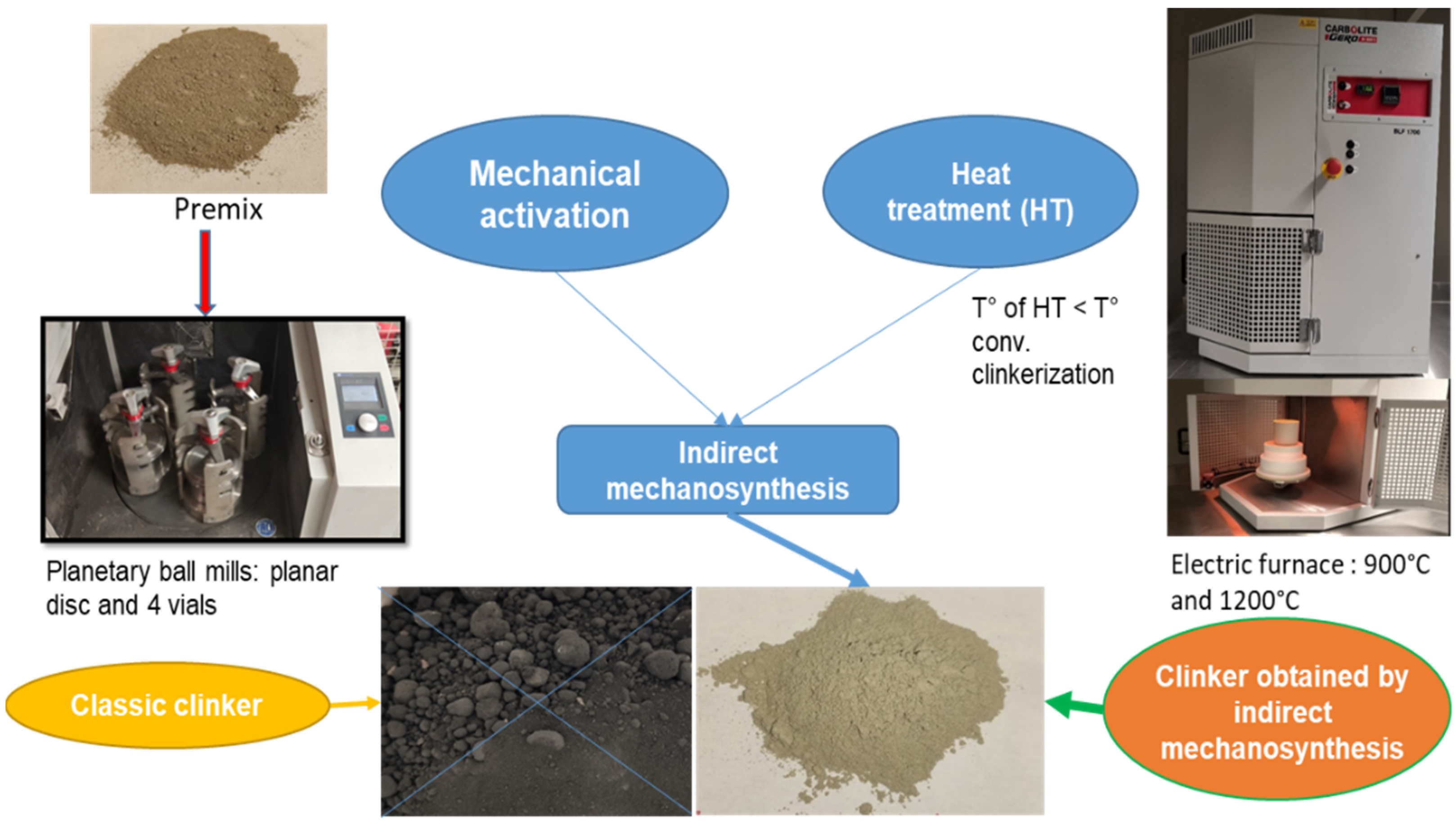
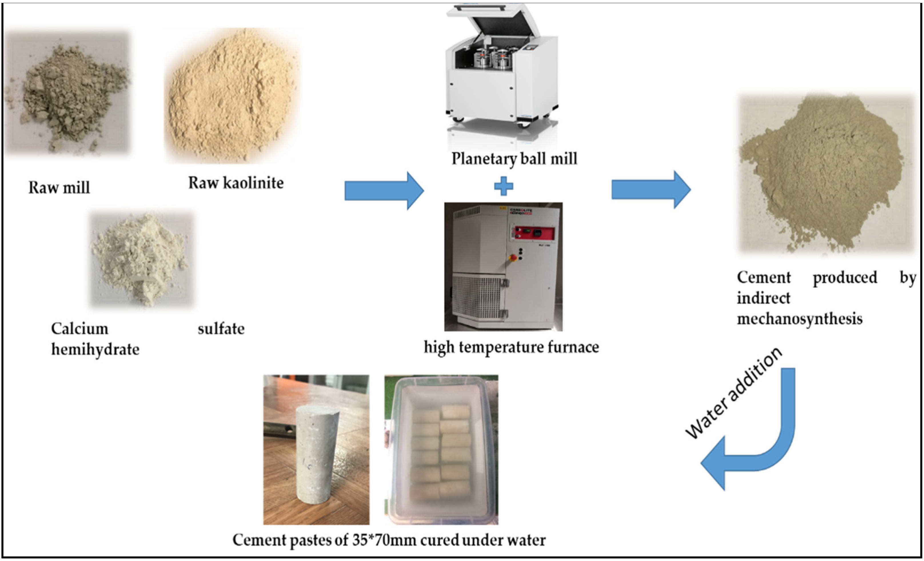
2.2.1. Indirect Mechanosynthesis

The indirect mechanosynthesis clinkerization process is made by combining 2 techniques: a high-energy ball milling to mechanically activate the premix and heat treatment to perform the clinkerization, as shown in Figure 1.
A planetary ball mill (PM 400, RETSCH, Haan, Germany) was used to perform the mechanical activation. This device has a planetary disc on which four vials are mounted. The vials rotate in the opposite direction of the disc. In this study, we choose to use a ball/powder ratio of 4 and a milling time of 15 min, and the rotation speed of the disc and vials are 400 and 800 rpm, respectively.
Before the clinkerization, the premix modification is performed by adding kaolinite until reaching the LSF, SM and AM 0.97 ± 0.05,2.00 ± 0.50 and 2.0 ± 0.50 (Table 2) chosen according to the index used in the cement industries and also found in the literature [2,37]:
  • LSF (lime saturation factor) = CaO ( ( 2.8   ×   SiO 2 ) + ( 1.18   ×   Al 2 O 3 ) + ( 0.65   ×   Fe 2 O 3 ) )
  • SM (Silica Modulus) = SiO 2 Al 2 O 3 + Fe 2 O 3
  • AM (Alumina modulus) = Al 2 O 3 Fe 2 O 3
The heat treatment was performed by a high-temperature bottom loading furnace (BLF 17/3, Carbolite Gero, Sheffield, UK). Different temperatures of 900°C and 1200 °C are applied for heat treatment of 60 min.
This study investigated cement production by indirect mechanosynthesis using a different method for controlling C3A hydration. This method consisted of introducing the calcium sulfate “ C S ¯ into the premix before using the indirect mechanosynthesis (Figure 2) to show that it is possible to produce cement directly with our process without additional milling.

2.2.2. Characterization of Powders (Clinkers & Cements) and Cements Pastes

The chemical composition of all materials used in these studies was conducted by X-ray fluorescence spectroscopy (S2 Ranger, BRUKER, Karlsruhe, Germany). The structural analysis includes an X-ray diffraction diffractometer (D2 Phaser, BRUKER, Karlsruhe, Germany) with a continuous scanning mode and Cu Kα radiation (λ = 0.1541 nm). For the XRD analysis, we used a 2θ range of 2–70° with a 0.02° increment for each 0.15 s. For the evaluation of the XRD analysis, the software DIFFRAC.EVA (BRUKER, Karlsruhe, Germany) with ICDD PDF 4 (Newtown Square, PA, USA) was employed. For the quantification phases analysis, the DIFFRAC.TOPAS software was used (BRUKER, Karlsruhe, Germany).
The particle size distributions are measured with an LS 13 320 XR laser particle size analyzer from BECKMAN COULTER (Villepinte, France). The dispersion method of samples in liquids with a size distribution between 0.01 and 2000 μm is used. In this study, the liquid used is ethanol to avoid the hydration of the samples studied.
The sample dispersion method is coupled with PIDS (polarization intensity differential scattering) technology for better accuracy for very fine particles.
For the dispersion of the particles, sound waves to break up the aggregates are used on a mixture of a few milligrams of product in a volume of ethanol which is placed and shaken for at least 2 min with a magnetic stirrer. The analysis of the products is repeated at least 3 times to ensure the repeatability of our results.
To study the mechanical performances of the cements produced by indirect mechanosynthesis, cement pastes were made with the addition of water. Consistency tests were carried out to determine the optimal quantity of water to be added as indicated in the NF EN 196-3 standard. Thus, water/binder ratios from 0.7 to 0.9 were used to prepare the cement pastes, which were then introduced into cylindrical tubes of Φ: 35 mm, L: 70 mm (Error: Reference source not found). The samples were unmoulded after 24 h and stored in the water tank at room temperature for 7 curing days. In addition, commercial cements CEM I and CEM III pastes were made to compare their mechanical performances with our cement. Compression tests were carried out with 300 kN equipment (Syntech, 3R, Montauban, France). For each product mechanically tested, 4 samples were produced with a loading speed of 2.4 kN/s.
For the morphological observation of the clinkers and cement made by the indirect mechanosynthesis, a scanning electron microscope (SUPRA 55VP, Zeiss, Oberkochen, Germany) coupled with an energy-dispersive spectrometer (EDS) (QUANTAX, BRUKER, Karlsruhe, Germany) from the ISTeP laboratory from Sorbonne university was used.

3. Results and discussions

3.1. Clinker Production
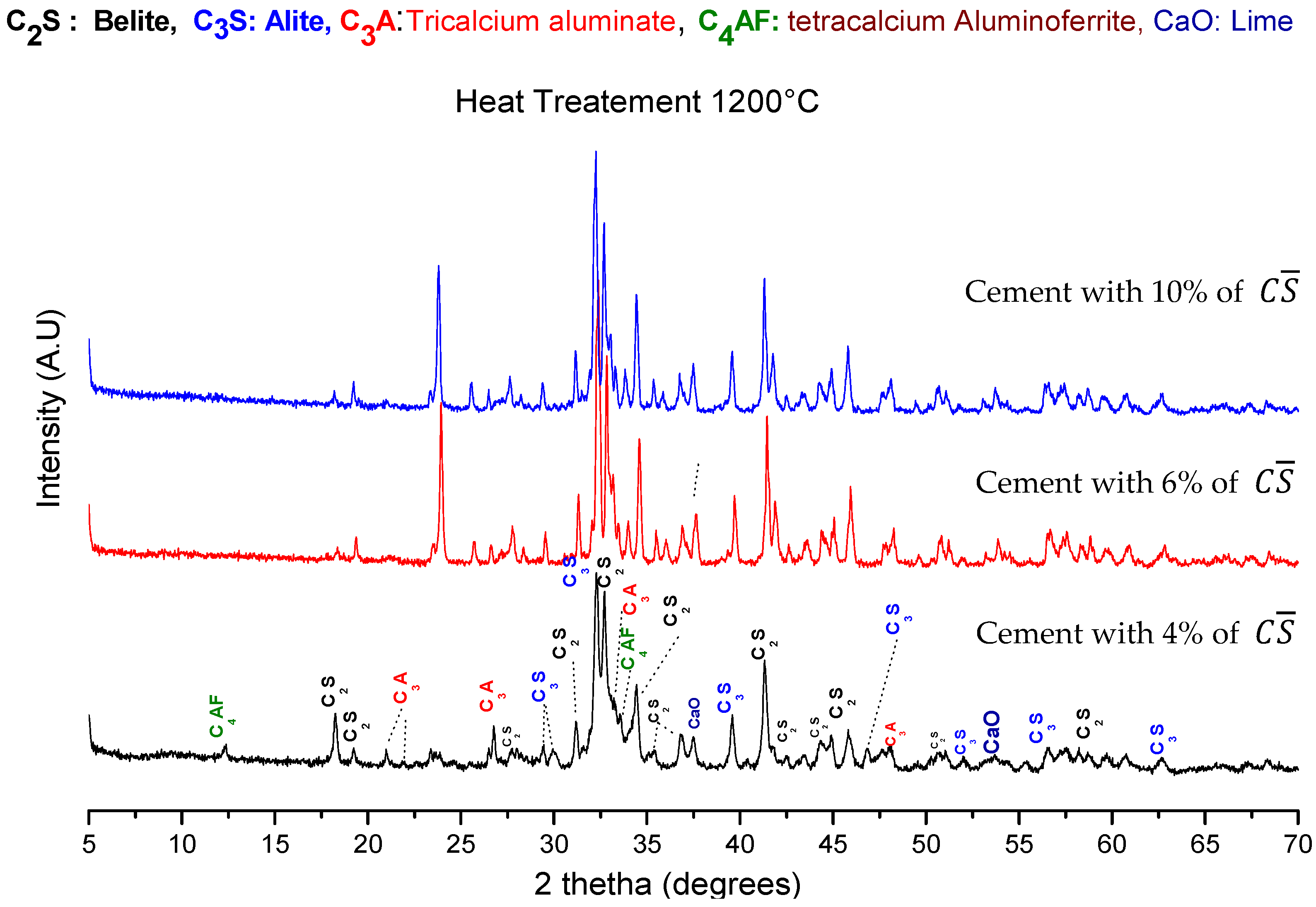
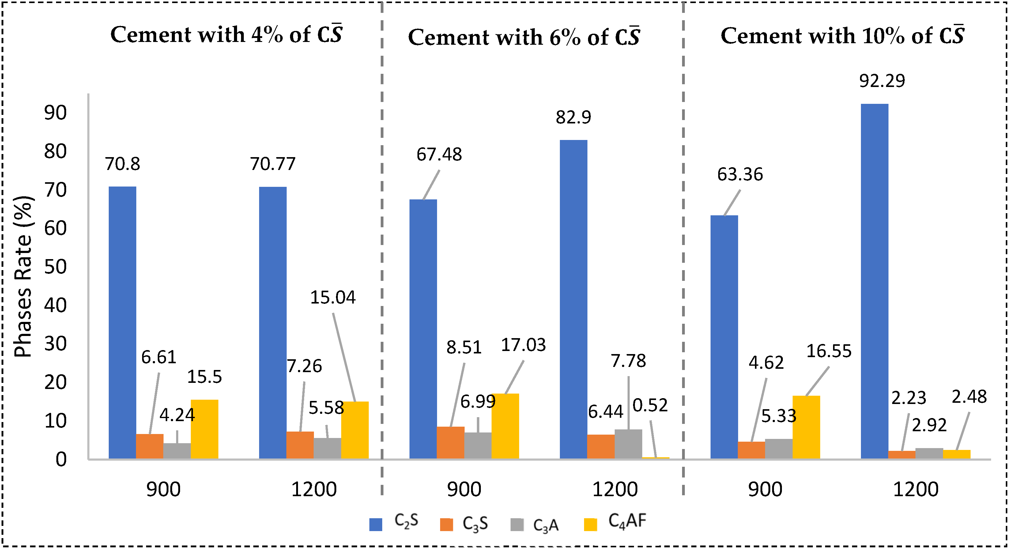
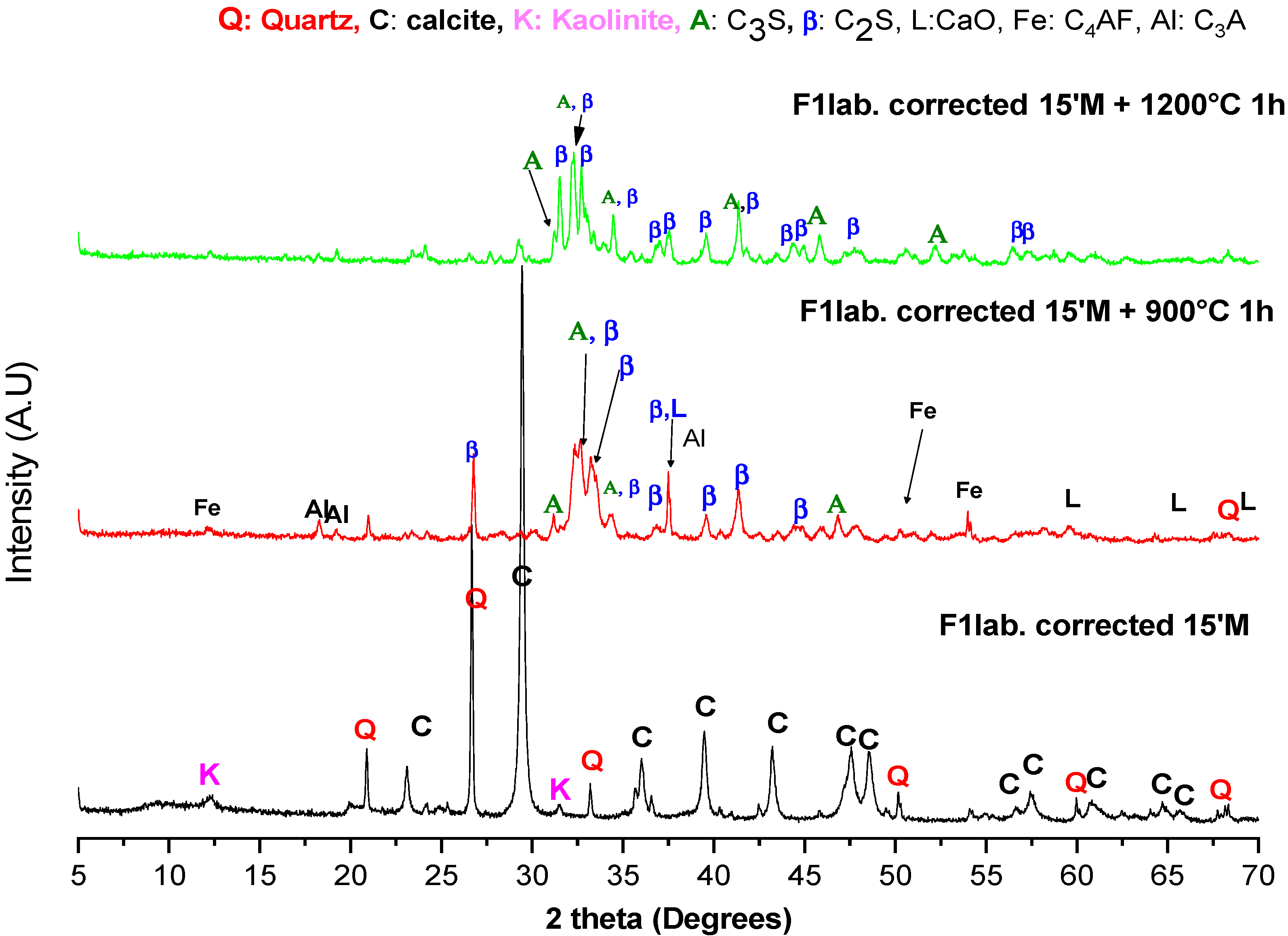
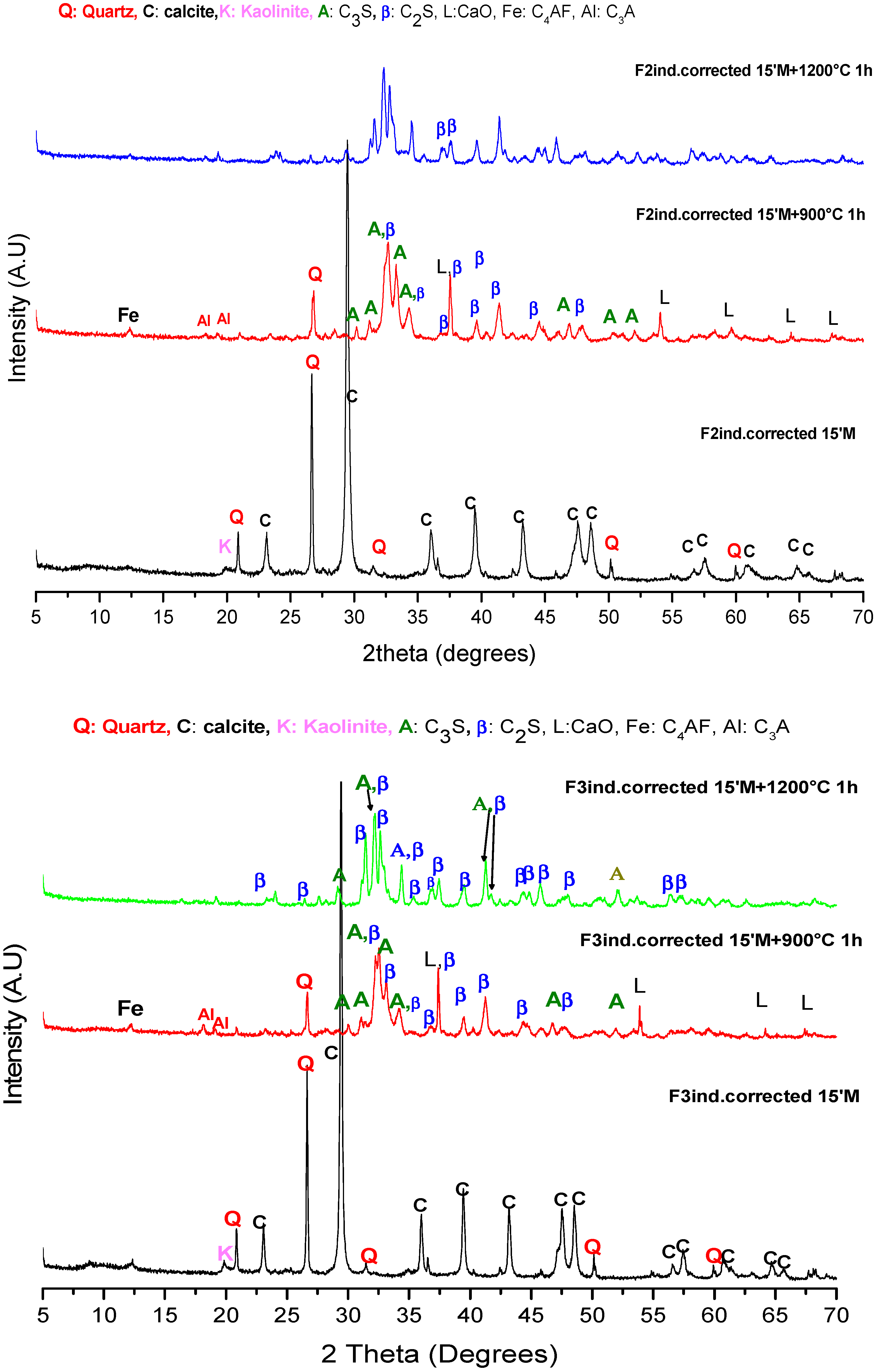
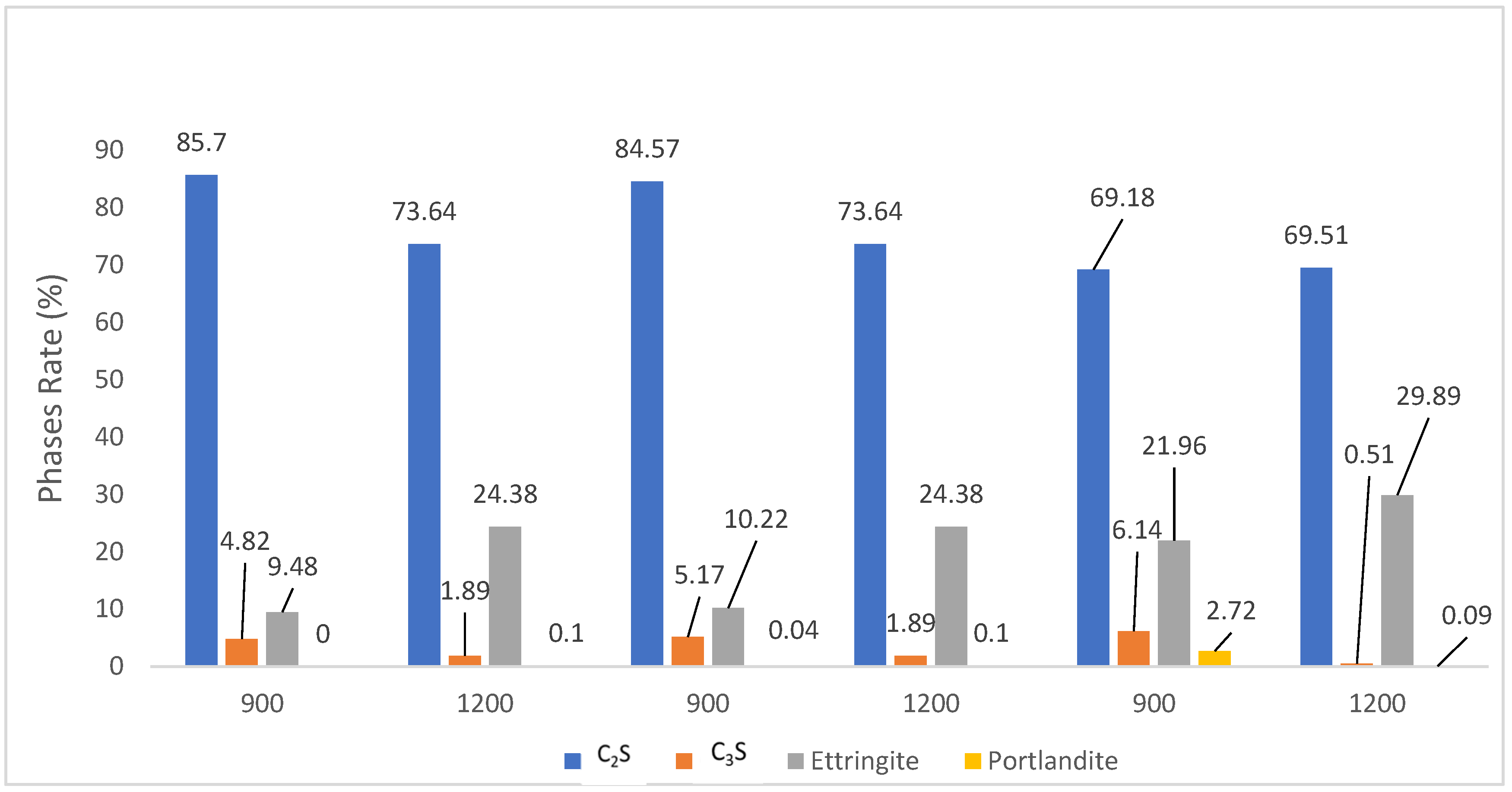
3.1.1. XRD

Figure 3 shows the diffraction patterns of the three premixes used in our study. Three crystalline structures in those materials, rhomboidric calcite (PDF#01-083-1762), triclinic kaolinite (PDF#00-003-0058) and hexagonal quartz (PDF#00-046-1045) are found in those premixes.
Table 3 shows the crystal phase quantifications of the premixes constituent used in this study. It is found that the calcite (CaCO3) is the predominant part, the quartz (SiO2) is present but at a lower intensity, and kaolinite (Al2Si2O5(OH)4) has the lowest presence.
Figure 4 illustrates the F1lab. diffraction pattern corrected by the addition of kaolinite. The diffraction pattern of the milled premix Flab1.corrected shows us the presence of some peaks of kaolinite after 15 min of milling. In the previous study [14], at 15 min of milling, the total disappearance of the kaolinite peaks is recorded. This difference may be due to the amount of kaolinite introduce is higher in this current study.
As shown in the previous article, indirect mechanosynthesis produces the main constituent of the clinker (C3S, C2S, C3A, C4AF), as observed in Figure 4. Some quartz peaks remain for the heat treatment of 900 °C, but their intensity has significantly decreased, as seen in Table 3 and Table 4. The amount of quartz dropped from 16.50% to 7.34%.
For the heat treatment of 1200 °C, all quartz peaks disappeared and were quantified at 0.24% with the TOPAS software. For lime (CaO), all peaks have disappeared from the diffraction pattern. Therefore, the quantification of the remaining lime phase is 1.62%.
The other clinkers produced by indirect mechanosynthesis (Figure 5) show the same results when the corrected F2ind. and F3ind. are used. The clinker’s main constituents (C3S, C2S, C3A, C4AF) are also produced for heat treatment of 900 and 1200 °C. Besides, it is observed in the diffraction pattern that quartz and lime (CaO) are still present in the clinkers produced at 900 °C and disappear entirely for heat treatment of 1200 °C.
Table 4 provides the quantification of the phases of all clinkers made by indirect mechanosynthesis with the 3 premixes used.
It is shown that regardless of the premix and the heat treatment temperature, a belite clinker is produced with a large proportion of β-C2S. In addition, with a higher temperature, the production of belite is increased. For the alite (C3S) constituent, the amount produced at 900 °C and 1200 °C is very low. For tricalcium aluminate (C3A) the production is higher at 900 °C than at 1200 °C. The amount of tetracalcium aluminate ferrite (C4AF) was higher with heat treatment of 900 °C.
In the current study, the CaO phase is produced less (<6%), contrary to the previous article [14]. Where a significant amount of CaO reached 11%, this can be explained by the kaolinite added to the F1lab. (used in the previous article), which has increased the amount of SiO2 in the premix and transformed it into another constituent (C3S, C2S).

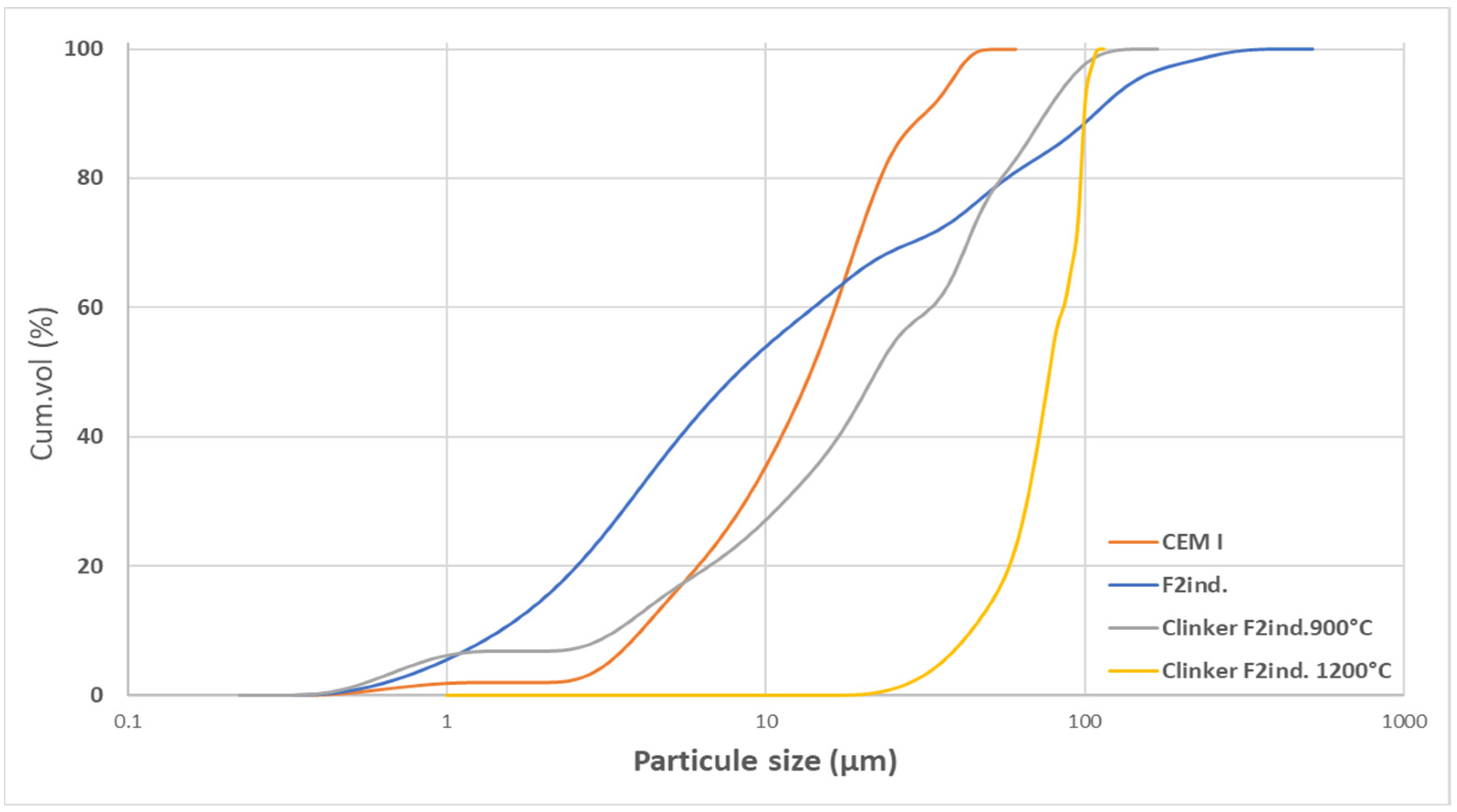
3.1.2. Particle Size Distribution (PSD)

Through mechanosynthesis, the clinker obtained is in powder form, unlike the clinker obtained with conventional clinkerization, which is in the form of nodules. For this reason, a comparison of the PSD of the Clinker F2ind. 900 °C and that of the premix F2ind. and also that of a commercial Portland cement (CEM I) was made.
Figure 6 and Table 5 shows that the clinker produced (clinker F2ind. 900 °C) has a very similar particle distribution to that of commercial cement. However, it is shown that for F2ind. 900 °C clinker, agglomerations are formed, which may be due to high energy milling [20,33,38]. Moreover, it can be attributed to the sintering (heat treatment). As a result of the indirect mechanosynthesis process, the clinker produced is in powder form. This result will impact the reduction in the energy used for the milling clinker when the gypsum is introduced for cement production.
In the case of the PSD of F2ind. 1200 °C clinker, the agglomeration phenomenon is more critical due to the higher heat treatment temperature used in this case (1200 °C) as observed in Table 5, where the D (90) of the cement produced with a 1200°C is higher than for the 900 °C. Therefore, grinding may be necessary for clinkers produced above 900 °C.

3.2. Cement Production
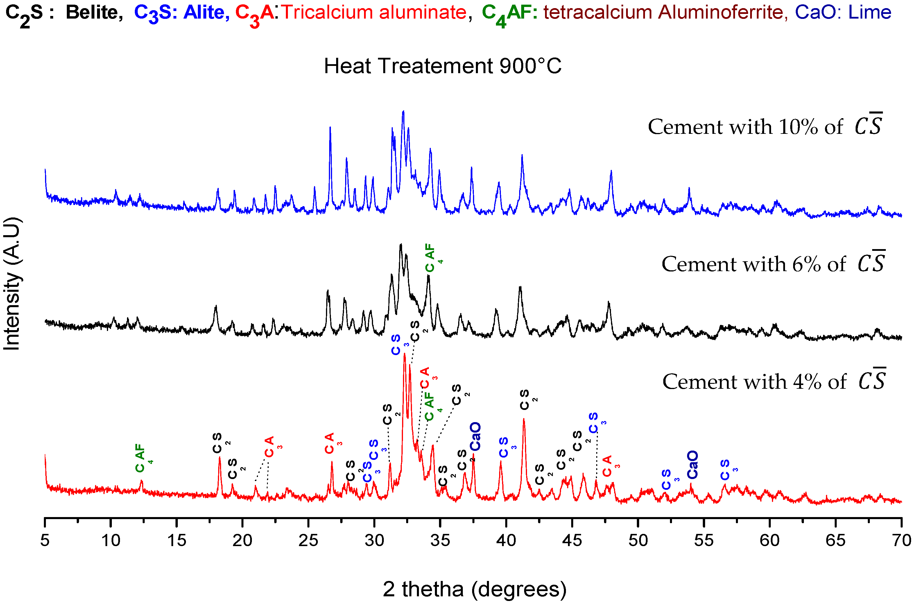
In this section, the results presented are obtained on cements produced from the F3ind. corrected premix.

3.2.1. XRD

Figure 7 shows the diffraction patterns of cements produced by adding calcium sulfates ( C S ¯ ) during the milling process (mechanical activation). The presence of the main crystal phases that should be present in clinker and cement can be observed. Furthermore, it is shown that C2S, C3S, C3A and C4AF are present in all the cements produced regardless of the temperature of the heat treatment and the amount of C S ¯ added before the milling.
Figure 8 shows the phase quantifications of the anhydre cement by indirect mechanosynthesis. It is found that our cements have a belitic nature, depending on the amount of C S ¯ and there is no big variation in the production of C2S with heat treatment of 900 °C. However, it is observed that the amount of belite produced increases with the increase in C S ¯   added with heat treatment of 1200 °C.
It is observed that the production of C3S was low whatever the temperature or the amount of C S ¯ used in order to produce cement. For the production of C3A, it was found that the production was also small.
Concerning the production of C4AF, a significant amount was obtained for all the cement produced at 900 °C 15.04%, 17.03%, 16.55%, respectively, for 4%, 6%, 10% of   C S ¯ used. For the cement produced at 1200 °C, only the cement prepared with 4% C S ¯ produced a significant amount of C4AF. As for the cement produced with 6 and 10% of C S ¯ the amount of C4AF found was not higher than 2.5% for the two cements.
Figure 9 gives the phase quantifications of the hydrated cement produced by indirect mechanosynthesis after 7 curing days.
The first results observed are the high amount of the belite residues after 7 days of curing, which may be due to the low reactivity of the C2S. In literature, it is shown that belite can take up two days of the induction period before the start of hydration and consequently can slow down the production of CSH [39].
It is also noted that small amounts of portlandite are produced during hydration; this can be attributed to the low amount of C3S obtained during the production process and the low reactivity of the C2S.
It was also observed that the production of ettringite was significant, and the highest production was observed with the cement with 10% C S ¯ at 1200 °C (29.89%), ettringite production at 900 °C was also highest compared to the two other cements produced at the same temperature. The ettringite production is due to the hydration of two constituents of the clinker C3A and C4AF. The equation of the hydration of C3A [2] is given in the following equations:
C 3 A + 3 C S ¯ H 2 + 26 H 2 O     C 6 A S ¯ 3 H 32
and concerning the equation for C4AF hydration with gypsum might be expressed by one of the following equations [38]:
C 4 AF + 4 CaS O 4   ·   2 H 2 O + 35 1 2 H 2 O   4 3 C 3 ( A 0.75 , F 0.25 )   ·   3 C S . ¯ H 31 + 2 3 FH 3
  C 4 AF + 4 CaS O 4 ·   2 H 2 O + 35 1 3 H 2 4 3 C 3 ( A 0.5 , F 0.5 )   ·   3 C S . ¯ H 31 + 1 3 AH 3 + 1 3 FH 3
  C 4 AF + 3 CaS O 4 · 2 H 2 O + 29 H 2 O     C 3 A   ·   3 C S . ¯ H 31 + CH + FH 3

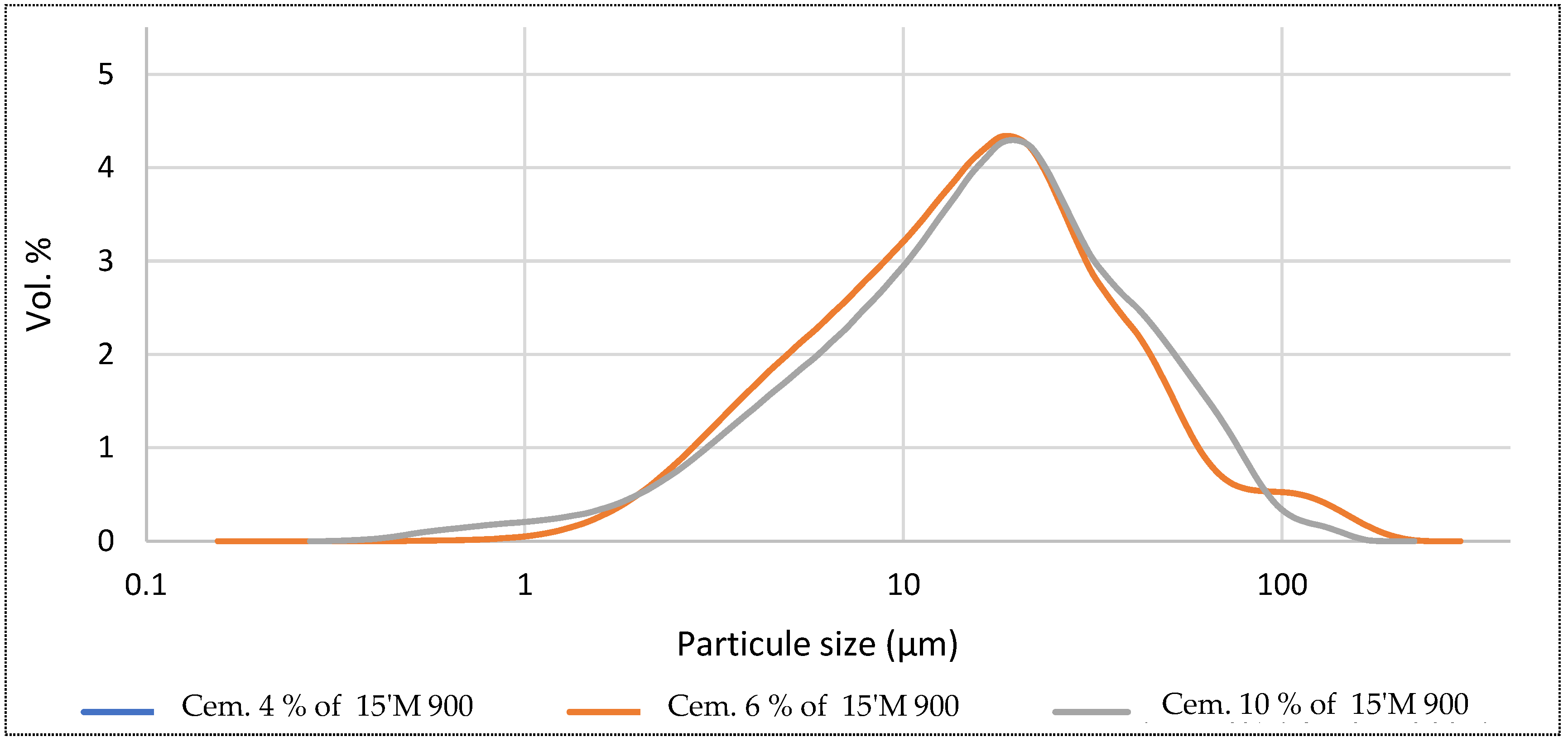
3.2.2. Particle Size Distribution of Cement

Figure 10 shows the particle size distribution of cement produced by indirect mechanosynthesis. The cement is obtained in a powder form for heat treatment of 900 °C as the clinker is shown in Figure 1.
The PSDs analysis shows that the cement produced with 4% C S ¯ has a multi-modal distribution, where the first range is found between 0.27 mm and 1.45 mm with a maximum peak at 0.68 mm and the second range is located between 2.1 mm to 5.8 mm with a maximum peak at 2.3 mm.
The third range is found between 5.8 mm and 31.5 mm, with a maximum peak at 19.6 mm. The fourth range is found between 31.5 mm and 60.52 mm, with a maximum peak at 41.61 mm. Finally, the last range is located between 60.52 mm and 105.93 mm, with a maximum peak at 80.074 mm.
The cement produced with 6% C S ¯ has a monomodal distribution; the range is found between 0.16 mm and 295.53 mm, with a maximum peak at 18.00 mm.
Concerning the cement produced with 10% C S ¯ with a monomodal distribution, the range is found between 0.16 mm and 185.38 mm, with a maximum peak of 19.76 mm.
Concerning the heat treatment of 1200 °C during the indirect mechanosynthesis process, the particles sintered together and created larger cement particles. In this case, the milling is suitable for cement to be used in the best conditions.

3.2.3. Compressive Strength (CS) of the Cement Paste

To study the hydraulicity of the cement produced by indirect mechanosynthesis, cement pastes were made and mechanically tested and compared to two conventional cements.
Table 6 shows the CS of all the pastes tested after 7 days of curing. For the two conventional cements, the CS of the CEM I and III reached 23.03 and 19.04 MPa after 7 days of curing. Concerning the three cements produced at 900 °C with 10%, 6% and 4% of C S ¯ showed fewer performances than the commercial cement. The best results found with our cements are for an addition of 10% of C S ¯ with 3.60 MPa (900 °C) and 7.60 MPa (1200 °C).
This leak of performance compared to the performances of the commercial cements can be explained by the small amount of the C3S produced during the cement production by our process compared to the commercial cement. The small performances can also be due to the low reactivity of C2S for the production of C-S-H and a different PSD.
According to the results obtained in the production of cementitious pastes, it can be considered that our cements have performances close to those of masonry cement or hydraulic road binder.

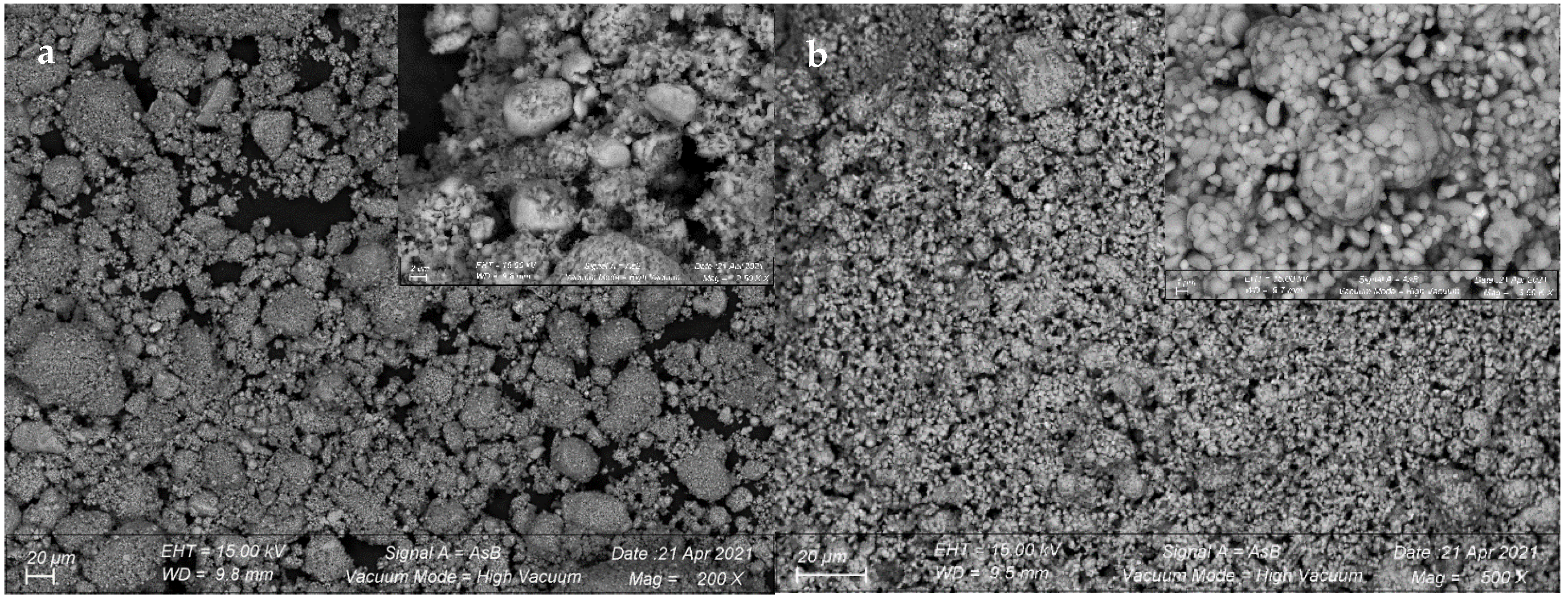
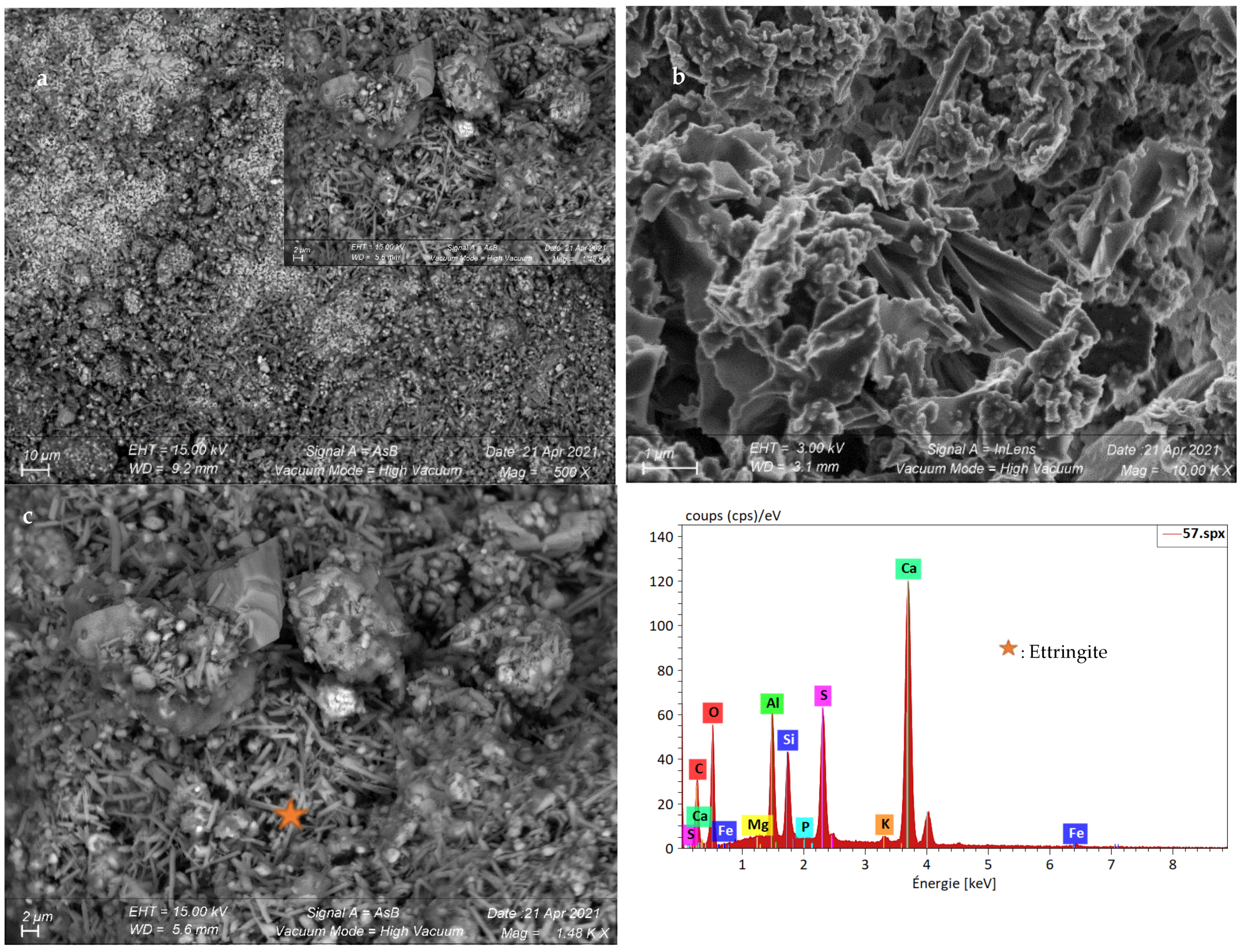
3.2.4. Morphology of the Cement Produced

The morphology of the cement produced at 900 and 1200 °C by indirect mechanosynthesis was studied, as shown in Figure 11.
The first picture (on the left) is related to the cement produced at 900 °C. Some spherical particles that may be related to the belite are observed [39]. For cement produced at 1200 °C, the shape of the belitic particles seems smoother and more abundant.
Figure 12 shows the morphology of the hydrated cement produced by our process of indirect mechanosynthesis. It is found that the presence of ettringite in the shape of needle particles, as confirmed by the X-ray diffraction analysis. The EDS analysis confirmed the ettringite presence, as shown in Figure 12. Some particles in the shape of some hexagonal particles form are observed and attributed to the portlandite.
It can also be seen from the photo (a,c) that there is still a significant amount of spherical particles associated with the belite, which confirms the result of the Rietveld quantification.

4. Conclusions

The previous work published in 2020 shows that clinkerization by mechanosynthesis allows us to produce clinker with heat treatment of 900 °C. In this work, we have continued the manufacture of cement and clinker using an indirect mechanosynthesis process by introducing C S ¯ before milling.
It was found that the cements produced are belitic cements. Phase quantifications by TOPAS software showed us that the belite is generally around 70%, with a more significant amount produced using 10% C S ¯ (92.29%) at 1200 °C. It was also noted that there was a significant production of C4AF in cements produced at 900 °C. The presence of belite is confirmed by the SEM analysis, with spherical particles characteristic of belite particles.
Regarding the mechanical performances of the cements produced by indirect mechanosynthesis, it is remarked that in general, the performances at 7 curing days of the pastes produced with our cements are weaker with 10% C S ¯ 3.60 and 7.60 MPa at 900 °C and 1200 °C, respectively, than the pastes produced with commercial CEM I and CEM III cements (23.03 and 19.14 Mpa, respectively).
The structural analysis of the cementitious pastes produced with our process showed that at 7 days, the quantity of remaining belite is high, resulting in a lack of reactivity. In addition, the production of portlandite is also low, which corroborates the lack of reactivity of C2S and the low presence of C3S in our cements. Finally, the important presence of ettringite in our cements is due to the hydration of C3A and C4AF in the anhydrous cement.
The next step of the study will be to work on the tempering of the products after the thermal treatments because we suspect that during the slow cooling of the product, transformations in the different structures are produced.

Author Contributions

Conceptualization, R.H., O.B.; methodology, O.B., R.H.; validation, O.B., R.H., C.F., S.M.; formal analysis, O.B., R.H.; investigation, O.B., R.H.; resources, O.B., R.H.; data curation, O.B., R.H.; writing—original draft preparation, O.B.; writing—review and editing, R.H., C.F.; visualization, O.B., R.H.; supervision, O.B., R.H.; project administration, R.H.; funding acquisition, C.F., S.M. All authors have read and agreed to the published version of the manuscript.

Funding

This research was funded by EFB (École Française du Béton).

Data Availability Statement

Not applicable.

Acknowledgments

We want to thank the EFB for financing and supporting the research carried out in the scope of the Concrete Materials Engineering Chair (ingénierie des bétons_IdB) of ESTP Paris. We also want to thank Omar BOUDOUMA ISTeP/UPMC for his time and expertise in the SEM.

Conflicts of Interest

The authors declare no conflict of interest.

References

  1. NF EN 197 1-Cement: Part 1: Composition, Specifications and Conformity Criteria for Common Cements; AFNOR: Saint-Denis, France, 2012.
  2. Taylor, H.F.W. (Ed.) Cement Chemistry, 2nd ed.; Thomas Telford Publishing: London, UK, 1997. [Google Scholar]
  3. Hewlett, P.C.; Liska, M. (Eds.) Lea’s Chemistry of Cement and Concrete, 5th ed.; Elsevier: Oxford, UK, 2019; ISBN 0750662565. [Google Scholar]
  4. IEA Technology Roadmap—Low-Carbon Transition in the Cement Industry. 2018. Available online: www.wbcsdcement.org. (accessed on 5 December 2018).
  5. Siddique, R.; Khan, M.I. Supplementary Cementing Materials; Springer: Berlin, Germany, 2011. [Google Scholar]
  6. Payá, J.; Monzó, J.; Borrachero, M.V.; Peris, E.; González-López, E. Mechanical treatments of fly ashes. Part III: Studies on strength development of ground fly ashes (GFA)—Cement mortars. Cem. Concr. Res. 1997, 27, 1365–1377. [Google Scholar] [CrossRef]
  7. Payá, J.; Monzó, J.; Borrachero, M.V.; Peris-Mora, E.; Amahjour, F. Mechanical treatment of fly ashes—Part IV. Strength development of ground fly ash-cement mortars cured at different temperatures. Cem. Concr. Res. 2000, 30, 543–551. [Google Scholar] [CrossRef]
  8. Behim, M.; Cyr, M.; Clastres, P. Physical and chemical effects of El Hadjar slag used as an additive in cement-based materials. Eur. J. Environ. Civ. Eng. 2011, 15, 1413–1432. [Google Scholar] [CrossRef]
  9. Kourounis, S.; Tsivilis, S.; Tsakiridis, P.E.; Papadimitriou, G.D.; Tsibouki, Z. Properties and hydration of blended cements with steelmaking slag. Cem. Concr. Res. 2007, 37, 815–822. [Google Scholar] [CrossRef]
  10. Schneider, M.; Romer, M.; Tschudin, M.; Bolio, H. Sustainable cement production-present and future. Cem. Concr. Res. 2011, 41, 642–650. [Google Scholar] [CrossRef]
  11. Scrivener, K.L. SPECIAL ISSUE-Future Cements Options for the Future of Cement. 2014. Available online: http://www.lc3.ch/wp-content/uploads/2014/09/0851_ICJ_Article.pdf (accessed on 6 March 2019).
  12. Gartner, E. Industrially interesting approaches to “low-CO2” cements. Cem. Concr. Res. 2004, 34, 1489–1498. [Google Scholar] [CrossRef]
  13. CEMBUREAU. Cementing the European Green Deal. 2020. Available online: https://cembureau.eu/green-deal/ (accessed on 5 June 2020).
  14. Hamzaoui, R.; Bouchenafa, O. Equivalent Cement Clinker Obtained by Indirect Mechanosynthesis Process. Materials 2020, 13, 5045. [Google Scholar] [CrossRef]
  15. Suryanarayana, C. Mechanical alloying and milling. Prog. Mater. Sci. 2001, 46, 1–184. [Google Scholar] [CrossRef]
  16. El-Eskandarany, M.S. Mechanical Alloying, Nanotechnology, Materials Science and Powder Metallurgy, 2nd ed.; William Andrew: Waltham, MA, USA, 2015. [Google Scholar]
  17. Gaffet, E.; Caër, G. Le Mechanical Milling. In Nanomaterials and Nanochemistry; Bréchignac, C., Houdy, P., Lahmani, M., Eds.; Springer: Berlin, Germany, 2008; pp. 455–471. [Google Scholar]
  18. Hamzaoui, R. Mécanosynthèse et Propriétés Magnétiques D’alliages Fe-Ni. Ph.D. Thesis, Université de Technologie de Belfort-Montbeliard, Belfort, France, 2004. [Google Scholar]
  19. Hamzaoui, R.; Bouchenafa, O.; Guessasma, S.; Leklou, N.; Bouaziz, A. The sequel of modified fly ashes using high energy ball milling on mechanical performance of substituted past cement. Mater. Des. 2016, 90, 29–37. [Google Scholar] [CrossRef]
  20. Bouchenafa, O.; Hamzaoui, R.; Bennabi, A.; Colin, J. PCA effect on structure of fly ashes and slag obtained by mechanosynthesis. Applications: Mechanical performance of substituted paste CEMI + 50% slag /or fly ashes. Constr. Build. Mater. 2019, 203, 120–133. [Google Scholar] [CrossRef]
  21. Hamzaoui, R.; Bouchenafa, O.; BEN MAAOUIA, O.; Guessasma, S. Mechanosynthesis for kaolinite activation: The impact of the substitution on the mechanical performances of mortar. Powder Technol. 2019, 355, 340–348. [Google Scholar] [CrossRef]
  22. Kumar, R.; Kumar, S.; Mehrotra, S.P. Towards sustainable solutions for fly ash through mechanical activation. Resour. Conserv. Recycl. 2007, 52, 157–179. [Google Scholar] [CrossRef]
  23. Bouaziz, A.; Hamzaoui, R.; Guessasma, S.; Lakhal, R.; Achoura, D.; Leklou, N. Efficiency of high energy over conventional milling of granulated blast furnace slag powder to improve mechanical performance of slag cement paste. Powder Technol. 2017, 308, 37–46. [Google Scholar] [CrossRef]
  24. Kumar, R.; Kumar, S.; Badjena, S.; Mehrotra, S.P. Hydration of mechanically activated granulated blast furnace slag. Metall. Mater. Trans. B 2005, 36, 873–883. [Google Scholar] [CrossRef]
  25. Zhao, F.-Q.; Ni, W.; Wang, H.-J.; Liu, H.-J. Activated fly ash/slag blended cement. Resour. Conserv. Recycl. 2007, 52, 303–313. [Google Scholar] [CrossRef]
  26. Alex, T.C.; Kalinkin, A.M.; Nath, S.K.; Gurevich, B.I.; Kalinkina, E.V.; Tyukavkina, V.V.; Kumar, S. Utilization of zinc slag through geopolymerization: Influence of milling atmosphere. Int. J. Miner. Process. 2013, 123, 102–107. [Google Scholar] [CrossRef]
  27. Kumar, S.; Mucsi, G.; Kristály, F.; Pekker, P. Mechanical activation of fly ash and its influence on micro and nano-structural behaviour of resulting geopolymers. Adv. Powder Technol. 2017, 28, 805–813. [Google Scholar] [CrossRef]
  28. Temuujin, J.; Rickard, W.; van Riessen, A. Characterization of various fly ashes for preparation of geopolymers with advanced applications. Adv. Powder Technol. 2013, 24, 495–498. [Google Scholar] [CrossRef]
  29. Hamzaoui, R.; Guessasma, S.; Abahri, K.; Bouchenafa, O. Formulation of modified cement mortars using optimal combination of fly ashes, shiv and hemp fibres. J. Mater. Civ. Eng. 2020, 32, 04019354. [Google Scholar] [CrossRef]
  30. Malhouroux-Gaffet, N.; Gaffet, E. Solid state reaction induced by post-milling annealing in the FeSi system. J. Alloys Compd. 1993, 198, 143–154. [Google Scholar] [CrossRef]
  31. Öksüz, K.E.; Apaydın, F.; Bozdağ, A.E.; Çevik, M.; Özer, A. Phase and Morphological Evaluation of Mechanically Activated Sintered YAG Powders. Procedia Mater. Sci. 2015, 11, 44–48. [Google Scholar] [CrossRef]
  32. Farnè, G.; Ricciardiello, F.G.; Podda, L.K.; Minichelli, D. Innovative milling of ceramic powders: Influence on sintering zirconia alloys. J. Eur. Ceram. Soc. 1999, 19, 347–353. [Google Scholar] [CrossRef]
  33. Suryanarayana, C. Mechanical alloying and milling; Marcel Dekker. 2004. Available online: https://www.crcpress.com/Mechanical-Alloying-And-Milling/Suryanarayana/p/book/9780824741037 (accessed on 22 January 2019).
  34. Balaz, P. Applied Mechanochemistry. In Mechanochemistry in Nanoscience and Minerals Engineering; Springer: Berlin/Heidelberg, Germany, 2008; pp. 297–405. [Google Scholar] [CrossRef]
  35. Andini, S.; Bolognese, A.; Formisano, D.; Manfra, M.; Montagnaro, F.; Santoro, L. Mechanochemistry of ibuprofen pharmaceutical. Chemosphere 2012, 88, 548–553. [Google Scholar] [CrossRef] [PubMed]
  36. Zerzouri, M.; Bouchenafa, O.; Hamzaoui, R.; Ziyani, L.; Alehyen, S. Physico-chemical and mechanical properties of fly ash based-geopolymer pastes produced from pre-geopolymer powders obtained by mechanosynthesis. Constr. Build. Mater. 2021, 288, 123–135. [Google Scholar] [CrossRef]
  37. Kurdowski, W. Cement and Concrete Chemistry; Springer: Dordrecht, The Netherlands, 2013. [Google Scholar]
  38. Fukuhara, M.; Goto, S.; Asaga, K.; Daimon, M.; Kondo, R. Mechanisms and kinetics of C4AF hydration with gypsum. Cem. Concr. Res. 1981, 11, 407–414. [Google Scholar] [CrossRef]
  39. Campbell, D.H. Microscopical Examination and Interpretation of Portland Cement and Clinker, 2nd ed.; Portland Cement Association: Skokie, IL, USA, 1999. [Google Scholar]
Figure 1. Illustration of the clinkerization process by indirect mechanosynthesis.
Constrmater 02 00014 g001
Figure 2. Process of production of cement by indirect mechanosynthesis.
Constrmater 02 00014 g002
Figure 3. Diffraction patterns of the 3 premixes used.
Constrmater 02 00014 g003
Figure 4. Diffraction patterns of the milled premix F1lab.corrected, and the clinker produced by indirect mechanosynthesis.
Constrmater 02 00014 g004
Figure 5. Diffraction patterns of the milled premix F2ind. and F3ind. corrected and the clinkers produced by indirect mechanosynthesis.
Constrmater 02 00014 g005
Figure 6. Particle size distribution of CEMI and clinker produced by indirect mechanosynthesis.
Constrmater 02 00014 g006
Figure 7. Diffraction patterns of cement produced by indirect mechanosynthesis at different heat treatments.
Constrmater 02 00014 g007aConstrmater 02 00014 g007b
Figure 8. Phases quantifications of the anhydre cement produced by indirect mechanosynthesis.
Constrmater 02 00014 g008
Figure 9. Phases quantifications of the hydrated cement produced by indirect mechanosynthesis after 7 days of curing.
Constrmater 02 00014 g009
Figure 10. Particle size distribution of CEM produced by indirect mechanosynthesis.
Constrmater 02 00014 g010
Figure 11. SEM micrographs showing the particles of the anhydre cement produced by indirect mechanosynthesis at (a) 900 °C (b) 1200 °C.
Constrmater 02 00014 g011
Figure 12. SEM micrographs showing the hydrated cement cured produced by indirect mechanosynthesis at 1200 °C cured for 7 days (a,b), EDS analysis of the sample (c).
Constrmater 02 00014 g012
Table 1. Chemical composition of the industrial and laboratory premix used.
CaOSiO2Al2O3Fe2O3MgOK2OTiO2SO3MnONa2OLSF *SM **AM ***
Limestone96.791.30.630.220.50.16000.070
Kaolinite0.569.3724.081.540.60.382.850.300
F1lab.77.5314.915.320.480.520.20.570.060.0601.622.5710.99
F2ind.73.0113.834.643.4921.550.230.670.1301.581.71.33
F3ind.75.4412.594.583.481.21.4500.420.0601.761.561.32
Calcium sulfate hemihydrate C S ¯ 40.211.410.670.060.70.08051.0305.3
*: Lime saturation factor; **: Silica Modulus, ***: Alumina Modulus.
Table 2. Chemical composition of the mixes used for the clinkerization process.
CaOSiO2Al2O3Fe2O3MgOK2OTiO2SO3MnOLSF *SM ** AM ***
F1lab. corrected66.9320.717.32.990.520.230.810.10.050.982.012.44
F2ind. corrected65.0319.946.783.271.851.420.520.630.120.991.982.07
F3ind. corrected65.3220.267.213.21.121.310.380.40.050.971.942.24
*: Lime saturation factor; **: Silica Modulus, ***: Alumina Modulus.
Table 3. Phases quantification (TOPAS) of the premixes used.
F1lab. Corrected F2ind. CorrectedF3ind. Corrected
Quartz16.50%15.26%15.52
Calcite72.95%81.46%79.05
Kaolinite10.75%3.28% 5.43
Table 4. Phases quantifications (TOPAS) of the clinkers produced.
F1lab. 15′MF2ind. 15′MF3ind. 15′M
900 °C1200 °C900 °C1200 °C900 °C1200 °C
α-C2S4.87%12.12%6.93%10.33%5.91%11.23%
β-C2S49.14%69.43%42.41%72.39%56.82%76%
C3S2.44%2.21%4.94%6.52%4.08%5.5%
C3A13.59%5.38%13.1%3.51%6.87%5.2%
C4AF19.3%9%20.69%5.79%16.18%0.31%
Lime3.31%1.62%5.5%1.33%4.79%1.76%
Quartz7.34%0.24%6.43%0.12%5.35%0
Table 5. Median particle sizes: D (10), D (50) and D (90) of CEM I, F2ind, Clinker F2ind. 900 °C.
D (10)D (50)D (90)
CEMI 4.2514.4732.88
F2ind.1.366.3580.22
Clinker F2ind. 900 °C 3.5623.2278.84
Clinker F2ind. 1200 °C0.6715.15120.8
Table 6. Compressive strength at 7 days of curing of the cement pastes produced by indirect mechanosynthesis.
Cement PasteCompressive Strength (CS) (MPa)
900 °C1200 °C
10 %   C S ¯ 3.607.60
6 %   C S ¯ 2.935.60
4 %   C S ¯ 3.673.59
CEM I23.03
CEM III19.14
Publisher’s Note: MDPI stays neutral with regard to jurisdictional claims in published maps and institutional affiliations.

