Article

Glass-Ceramic Materials Obtained by Sintering of Vitreous Powders from Industrial Waste: Production and Properties

by
Diana M. Ayala Valderrama
1,*,
Jairo A. Gómez Cuaspud
2,
Nicoletta Taniolo
3 and
Aldo R. Boccaccini
3
1
Comprehensive Management of Agro-industrial Productivity and Services, Universidad Santo Tomas, Av. Universitaria No. 45-202, Tunja 150003, Colombia
2
Institute for Research and Innovation in Materials Science and Technology, Universidad Pedagógica y Tecnológica de Colombia, Av. Central del Norte 39-115, Tunja 150003, Colombia
3
Institute of Biomaterials, Department of Materials Science and Engineering, University of Erlangen-Nuremberg, 91058 Erlangen, Germany
*
Author to whom correspondence should be addressed.
Constr. Mater. 2021, 1(1), 63-79; https://doi.org/10.3390/constrmater1010004
Submission received: 13 February 2021 / Revised: 19 April 2021 / Accepted: 28 April 2021 / Published: 10 May 2021

Abstract

:
Glass-ceramics are advanced inorganic silicate materials that can be obtained by sintering glass powders using a careful temperature control to result in the densification, nucleation, and crystallization of the material. In the current work, three different samples were obtained starting from amorphous silicate materials derived from mixtures of metallurgical slag, coal fly ash, and glass cullet, mixed in different proportions. The as-received waste samples were heat-treated to high temperatures to achieve complete melting at 1200, 1300, and 1400 °C for two hours, performing a rapid cooling in order to yield an amorphous material (glass). The obtained frit was ball-milled to a powder, which was then cold pressed to obtain compact pellets. The thermal treatment of pellets was carried out at 800–1100 °C for 2 h followed by a cooling rate of 10 °C/min to obtain the final glass-ceramics. The microstructure of samples was evaluated with scanning electron microscopy (SEM), which showed heterogeneous conglomerates and clusters of ~20 microns. The formation of crystalline phases was corroborated by means of X-ray diffraction (XRD) analysis, showing the presence of anorthite in all samples. Depending on the sample composition, other crystalline phases such as augite, enstatite, and diopside were detected. Using the Debye–Scherrer equation, it was possible to find the average size of the nano-crystalline domains. The quantification of the non-crystalline or amorphous fraction was also performed. Additionally, the density and porosity of the materials were calculated using the procedures defined in the ASTM C373 and ASTM C20 standards, measuring density values in the range 2.2–3.1 g·cm−3. The apparent porosity was approx. 33% in the three materials. Raman spectroscopy analysis showed characteristic signals associated with crystalline phases containing alumina, silica, iron, and calcium. Overall, the study confirmed the possibility of obtaining glass-ceramics with fine (nanometric) crystal sizes from a combination of silicate waste and the capability of modifying the crystalline composition by changing the proportions of the different wastes in the initial formulations.

1. Introduction

The incorporation of industrial waste in the production processes has established itself as an excellent alternative to the final disposal of this type of waste, focused on minimizing the impact of the use of natural resources when waste materials are used to manufacture new products [1,2,3]. In this research, we focus on the use of three types of silicate industrial waste for the manufacture of glass-ceramics, namely slag, fly ash, and glass cullet. These are considered materials of great interest for applications such as construction components, fire resistant materials, and high temperature refractories. The increasing interest in the field of materials manufactured using industrial waste is not only attributed to an ecological interest for environmental protection, but also due to the possibility of achieving new materials (e.g., glass-ceramics) with novel properties for industrial use [4,5,6,7,8]. The three kinds of residues embraced in this research are suitable by-products for the production of glass-ceramic materials because they contain valuable oxides such as silica (SiO2) and alumina (Al2O3), which are required for the production of mechanically stable refractory materials. The use of glass cullet is advantageous due to its high amount of silica and its high surface reactivity, while slag and fly ash are attractive due to their high content of aluminosilicates, representing one of the main advantages in the valorization of industrial byproducts [3].
The use of fly ash, slag, and glass cullet has been considered in previous research as an attractive starting point for the development of cost-effective glass-ceramic products mostly by applying conventional melting technology [9,10,11,12,13], since the process of devitrification of the glass can be favored without the need of nucleating agents, which are substances of relatively high cost. Indeed, by-products can act as nucleating agents during the cooling process, allowing the nucleation and crystallization of the material to obtain glass-ceramic microstructures [14,15].
Recent studies have evaluated a range of industrial waste based glass-ceramics for technical applications [16,17,18,19,20], including highly porous materials for thermal insulation, and glass-ceramics from coal fly ash, steel slag, and vitrified municipal solid waste incinerator bottom ash with different crystalline phases, including diopside, anorthite, augite, gehlenite, and enstatite.
This work presents an alternative manufacturing method for the production of glass-ceramic materials based on powder technology and heat treatments with strict temperature control, which gives rise to the nucleation and crystallization processes during the sintering of amorphous silicate powder obtained from combinations of industrial waste [5]. The obtained glass-ceramic materials exhibit similar characteristics to conventional glass-ceramic materials obtained by the traditional route in terms of crystalline phases, density, and microstructure [21,22,23,24] but with the advantages brought by powder technology.

2. Materials and Methods

The raw materials used in this research were metallurgical slag, coal fly ash, and glass cullet, as described in a previous report [25]. The as-received powders were crushed separately using a planetary ball mill, obtaining particle sizes below 149 µm for the glass cullet, and below 75 µm for the slag and fly ash. Three sample mixtures were prepared for the experiments labeled as GC1, GC2, and GC3, where GC stands for “glass-ceramic” and (1, 2, 3) refer to the mixtures detailed in Table 1. The chemical compositions were determined by X-ray fluorescence (XRF, ZEISS, Oberkochen, Germany), using a PANalitical MiniPal 2 spectrometer operated at 20 KeV. The structural analysis of samples after the first heat treatment was performed in an X-ray diffractometer, PANanalytical X-Pert PRO 2.2, using Cu Kα radiation, with steps of 0.020° (2θ) in continuous mode from 2θ 10 to 90°, while the structural analysis of samples after the annealing process was carried out in a Bruker D8 Advance diffractometer (Karlsruhe, Germany) using Cu Kα radiation, 40 kV-40 mA, 2θ = 10–70°, step size 0.05°.
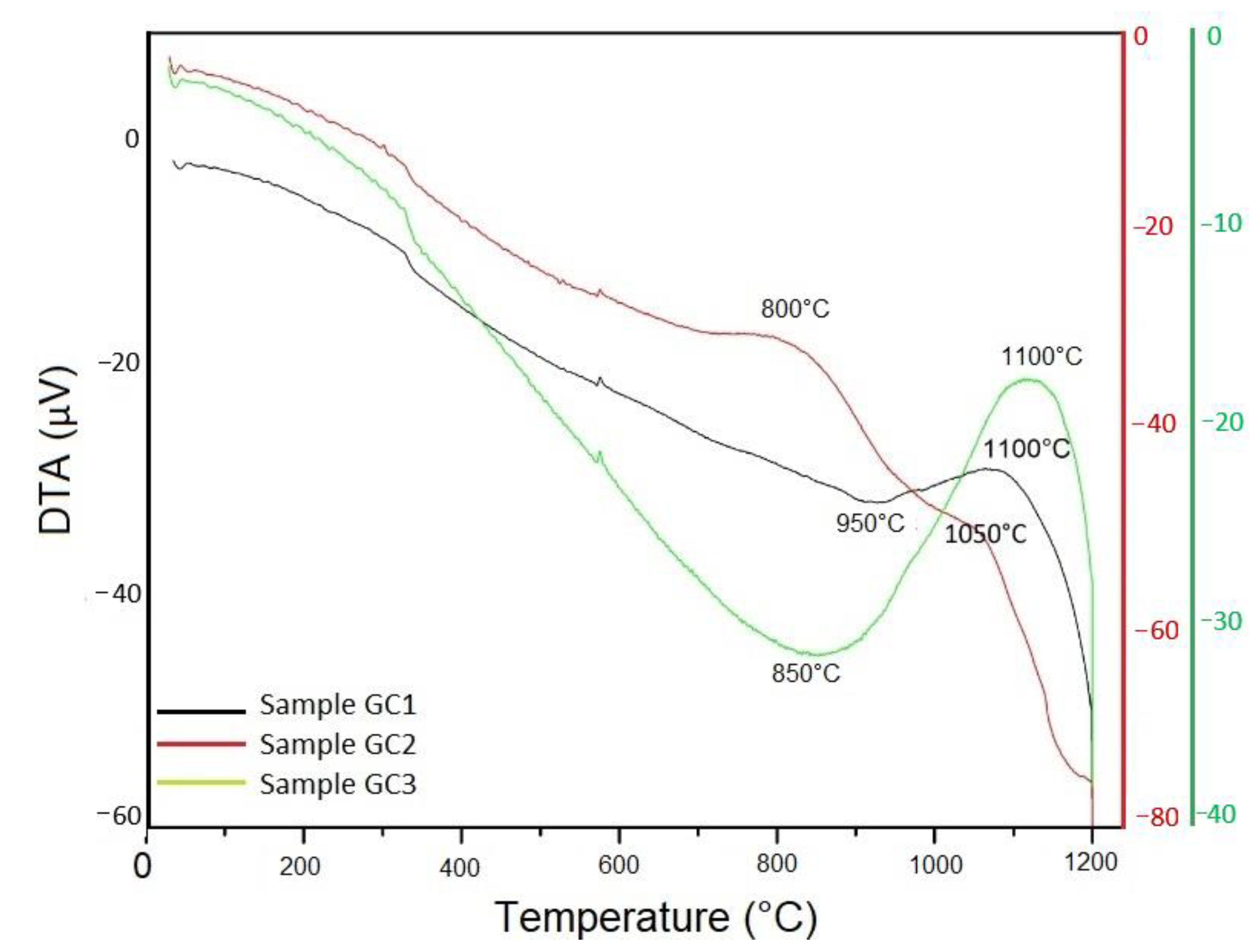
Vitreous powders were prepared by high-temperature heat treatment (melting), firstly at 1200 °C, then at 1300 °C, and finally at 1400 °C, for 2 h. The melting at these different temperatures was carried out separately to choose the correct melting temperature required to obtain amorphous glasses (see results below). After melting, the glass was cooled at 10 °C min−1 and milling was carried out to obtain powders of size <149 µm. Cold pressing was then used to obtain pellets of ~14 mm diameter and ~2.5 mm thickness using glycerol (BioXtra ≥ 99%) (5% by weight) as binder for the compaction of the powders at a compressive stress of 30 MPa. Next, the pellets were sintered, taking into account the temperatures indicated in Table 2, which were determined in accordance with differential thermal analysis (DTA) results for each material, with a cooling rate of 10 °C/min. For this study, it was necessary to prepare a minimum of 26 pellets for each composition for the different physical and mechanical analyses. The step-by-step fabrication process is shown in Figure 1.
The mixtures of as-received powders, the first heat treated at 1200–1400 °C, and the obtained glass-ceramic materials were examined by X-ray diffraction (XRD) analysis in powder samples (Bruker D8 Advance, Karlsruhe, Erlangen, Germany-CuKα radiation, 15.418 nm, 40 kV-40 mA, 2Ɵ = 10–70°, step size 0.05°). The identification of phases was carried out using the GSAS software (2018, General Structure Analysis System, GSAS-2) [26]. With the data provided by XRD analysis and using the Debye–Scherrer equation [27], it was possible to find the average size of the crystalline domains in the three samples.
Thermogravimetric analysis (DTA/TGA) was performed in a standard SDT Q600 20, DSC-TGA instrument (TA instruments, New Castle, DE, USA), using a heating rate of 10 °C min−1 under argon gas flow conditions (100 mL min−1) from room temperature up to 1100 °C.
Scanning electron microscopy (SEM) equipped with an energy-dispersed X-ray (SEM-EDX) detector, was performed on polished samples without gold covering (LEO 435 Electron Microscope Ltd., Cambridge, UK, and Ultra Plus, Zeiss, Jena, Germany). The detailed imaging information about the morphology and surface texture of the individual particles, as well as the composition of the powder samples, were studied.
The Raman characterization was performed in a HR-UV infinity microprobe equipment(Jobin-Yvon, Paris, France) in the range of 50–1500 cm−1, with an integration time of 10 s, accumulations of 20 Grid 600 planes/mm, using a laser source of 532 nm, an objective 100×, and a power of 50 mW output.
The density and porosity of the samples were calculated taking into account the procedures and standards as defined by the American Society for Testing and Materials (ASTM): ASTM C20-00 “Standard test methods for apparent porosity, water absorption, apparent specific gravity, and bulk density of burned refractory brick and shapes by boiling water,” and ASTM C373 Standard “Standard test methods for determination of water absorption and associated properties by vacuum method for pressed ceramic tiles and glass tiles and boil method for extruded ceramic tiles and non-tile fired ceramic white ware products.”

3. Results

The amorphous nature of the materials after melting was confirmed by XRD analysis (Figure 2). When the waste mixtures were heated at 1200 °C for 2 h, the formation of peaks corresponding to crystalline phases was evident (Figure 2a–c red color). These crystalline phases were not further characterized because such crystallized glasses were not relevant for the present study, which required amorphous materials. Therefore, it was necessary to increase the temperature to 1300 °C for 2 h, to obtain an amorphous material (Figure 2a–c blue color). The same procedure was performed at 1400 °C for 2 h (Figure 2a–c green color) in order to rule out the possible formation of subsequent crystalline phases. It was confirmed that at both 1300 and 1400 °C amorphous materials were obtained and with the objective of obtaining glass-ceramic materials with lower production costs, 1300 °C was considered as the preferred temperature for obtaining amorphous (vitreous) material for the present investigation [28,29] from the mixtures shown in Table 1.
The pellets obtained by cold pressing of amorphous powders were sintered as indicated in Figure 1. The temperatures were chosen according to TGA results (Figure 3) and the data presented in Table 2. Samples were characterization by XRD, SEM-EDS, Raman spectroscopy, bulk density, water absorption, and apparent porosity measurements.

3.1. X-Ray Diffraction (XRD) Analysis

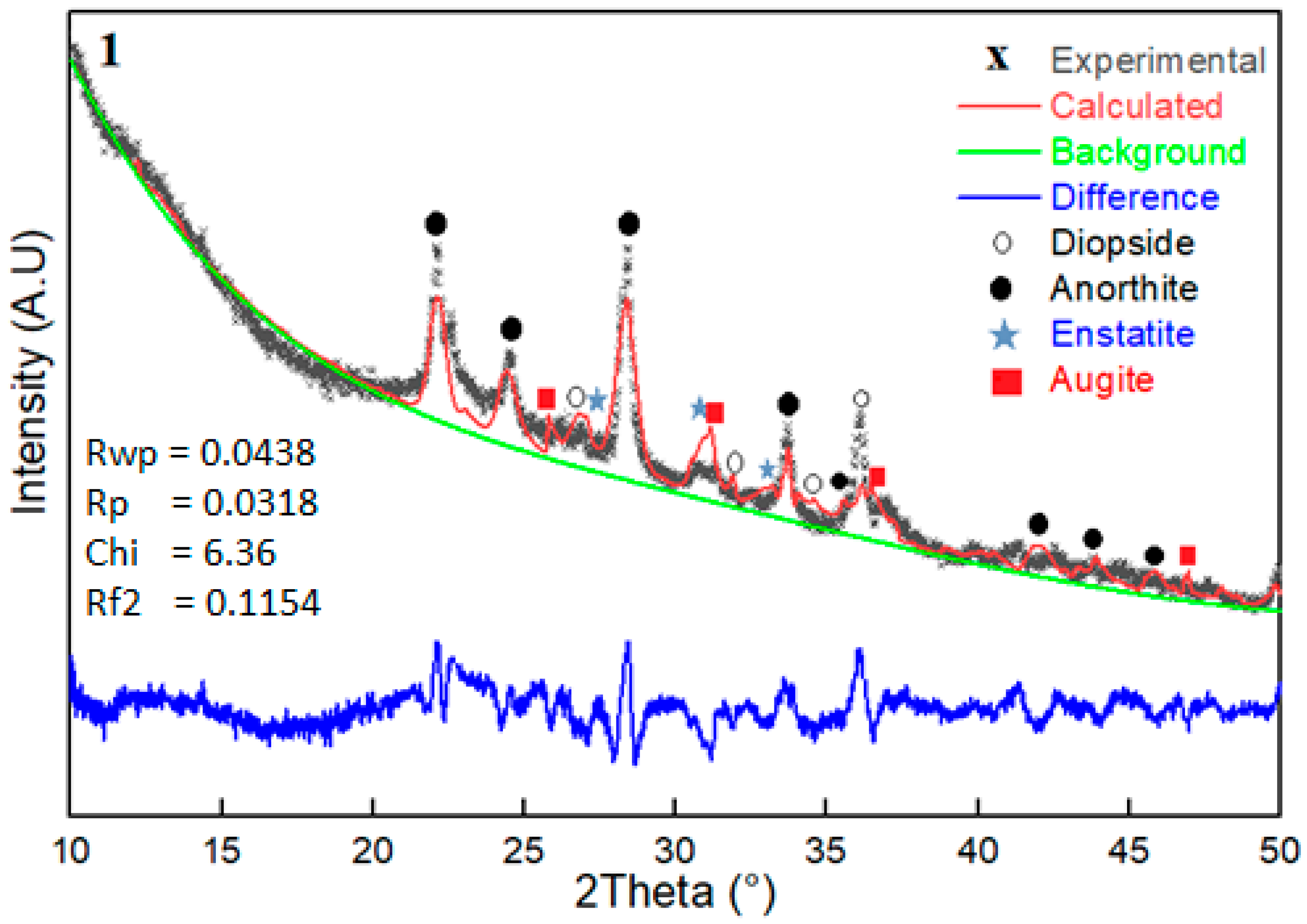
The effectiveness of the heat treatment for sintering and crystallization, in terms of the formation of crystalline phases, was confirmed by X-ray diffraction analysis (Figure 4, Figure 5 and Figure 6). In any crystallization process, there are specific structural changes that generate crystalline phases. In this investigation, anorthite, augite, enstatite, and diopside in different quantities were found for each material, which are common crystalline phases in glass-ceramic materials with high aluminosilicate content [30,31].
The process of structural refinement was done on the individual parameters (background intensity, asymmetry, scale factor, preferential orientation, signal height and width, sample transmission and structural factor), based on experimental diffractograms [31,32]. The phases were analyzed with the crystallographic data of each phase, including as standard the cell parameters, spatial group, and atomic positions of the phase of interest.
In the sintered materials, four crystalline phases were identified in different concentrations (Figure 4, Figure 5 and Figure 6). The diopside phase is usually present as the main phase in glass-ceramic materials obtained from the type of wastes investigated here [4,5,33]; however, in the present materials, the percentages of this phase were relatively low, between 5% and 15%. The principal phase was anorthite, which is known to impart good mechanical properties to glass-ceramic materials according to investigations in literature [34,35,36,37,38], followed by the augite phase [39,40,41]. The enstatite phase was also identified. These phases should contribute to the mechanical properties of the present glass-ceramics; however, it is anticipated that these properties will be highly influenced by the residual porosity after sintering (see below). The composition percentages of each phase were determined in each of the sintered glass-ceramic samples summarized in Table 3. The results confirmed the crystallization of the material during the sintering process, showing the feasibility of obtaining glass-ceramic materials from the considered mixture of industrial waste by powder technology. However, the superposition of some crystalline phases that coexist in the material is evident, as for example the reflection at 2Ɵ~36° in Figure 5 and Figure 6, which could be associated with diopsite and augite phases, according to the refinement carried out.
With the XRD data and using the Debye–Scherrer equation [27], the average sizes of the nano-crystalline domains of the three samples were determined, as shown in Table 4, which confirms that the sintering and crystallization process has generated glass-ceramic materials similar to those reported in literature [4,42,43]. The widening and low intensity of the peaks in the three diffractograms (Figure 4, Figure 5 and Figure 6) could be correlated with the formation of small crystallites compared to the samples, due to the elimination of a large number of carbonate species in the materials as a result of the heat treatments at high temperatures and the different proportions of each silicate residue used in the starting materials.
The glass-ceramic materials are characterized by the presence of an amorphous and a crystalline structure. The quantification of the non-crystalline or amorphous fractions was performed using X-ray diffractograms. The analysis data software was used considering the area under the curve and excluding the areas of the signals associated with crystallization. The percentages of amorphous phases were 35% for GC1, 34% for GC2, and 22% for GC3 samples, respectively.

3.2. Scanning Electron Microscopy and Energy Dispersive of X-ray Spectroscopy (SEM-EDS) Analysis

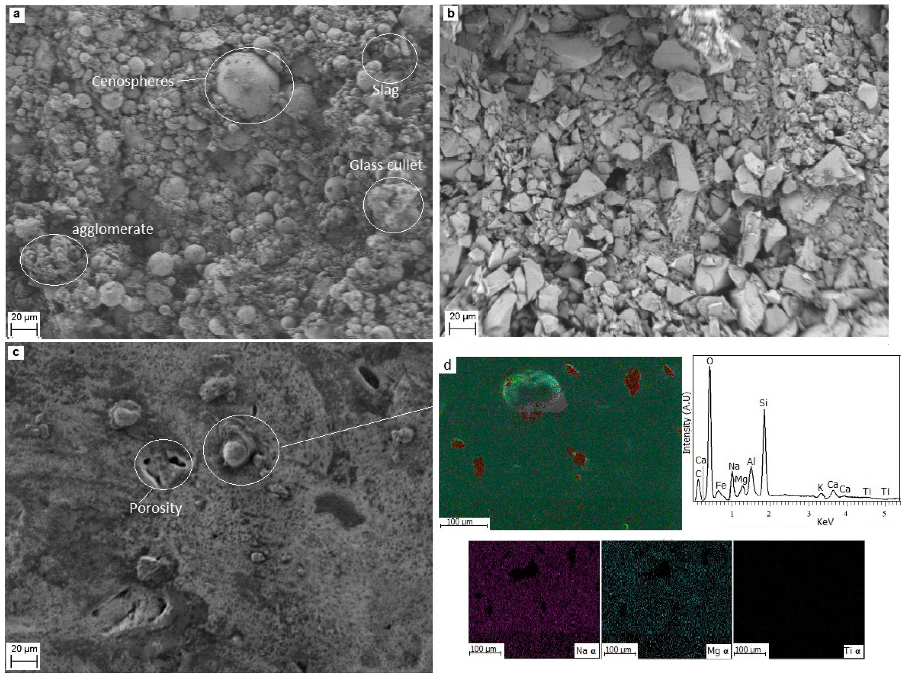
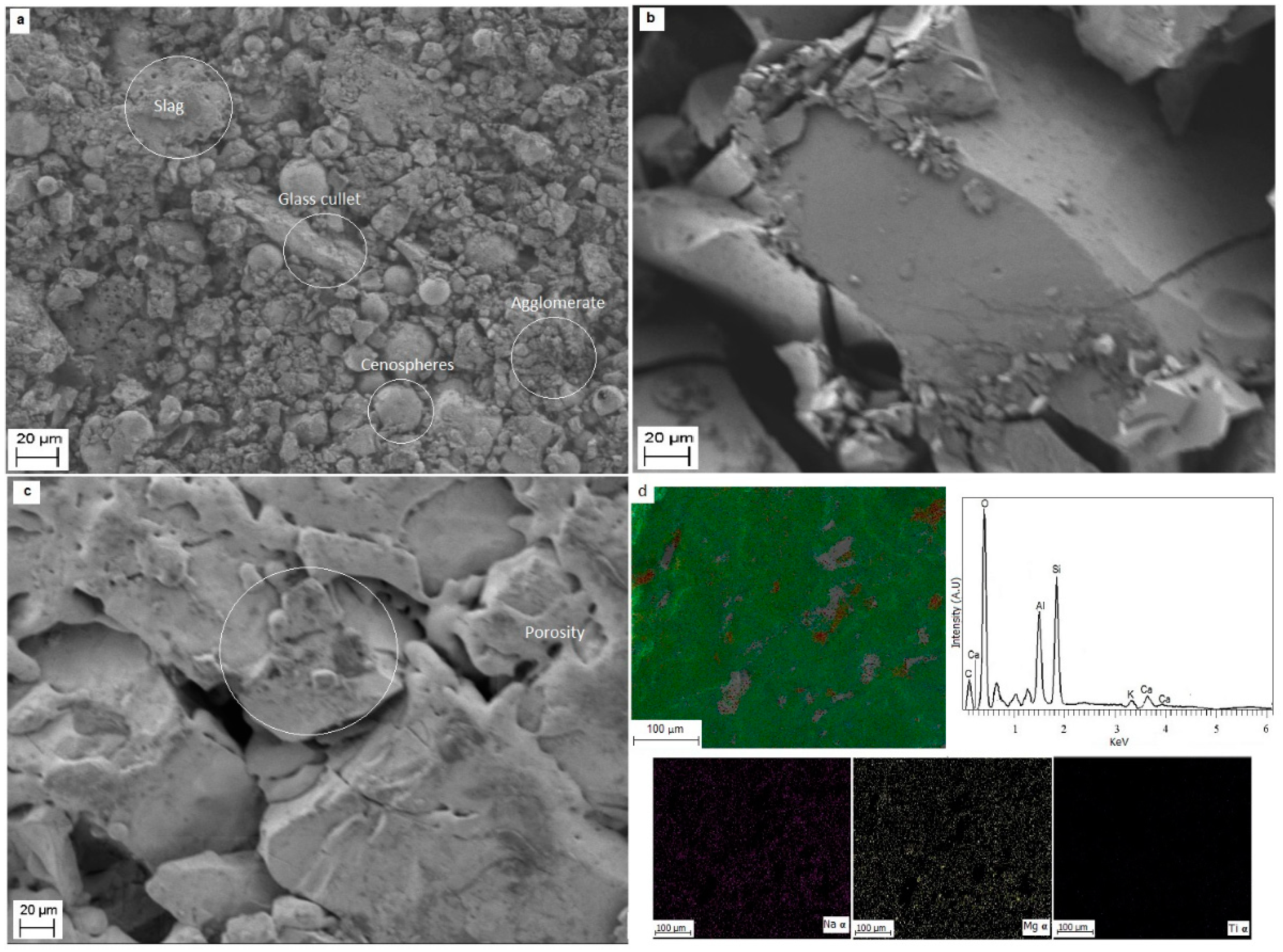
SEM-EDS was carried out to analyze the microstructure of samples before and after heat treatment. In the microstructure of the raw materials without heat treatment (Figure 7a, Figure 8a and Figure 9a), it is possible to observe particles of cenospheres, glass inlays, and some agglomerates. After heat treatment at 1300 °C for 2 h (Figure 7b, Figure 8b and Figure 9b), fragments of the amorphous matrix were observed, which was corroborated by XRD analysis (Figure 4, Figure 5 and Figure 6).
Figure 7, Figure 8 and Figure 9, corresponding to SEM analysis, show heterogeneous conglomerates and residual porosity, which are typical of partially densified glass-ceramic materials obtained by sintering and crystallization of vitreous powder. Changes in the microstructure in samples GC1, GC2, and GC3 are observed in the different stages of the sintering process, as shown in Figure 7c, Figure 8c and Figure 9c. Different microstructures are visible, which may be associated with different chemical compositions of the materials, the different shades in the micrographs can represent different phases. The microstructural features observed indicate that the volume of crystallization increases with increasing temperature and heat treatment time, visualizing some areas with a bright contrast that could be located in the vitreous matrix. The areas of high contrast (Figure 7, Figure 8 and Figure 9), according to previous research [1], could be related to crystalline phases, while the dark areas represent the amorphous phase. On the surface of all samples, scattered pores with a size of 1 to 2 µm are observable, also a dense microstructure, likely consisting of crystals embedded in a residual glass matrix, is observed [44].
After the sintering process, it was possible to observe fine grains in the microstructure that apparently became embedded in a significant amount of larger particles (Figure 7c, Figure 8c and Figure 9c), of size >15 µm, with open pores on the surface. Figure 7d, Figure 8d and Figure 9d show EDS results for the three sintered samples, indicating the presence of Si, Al, Na, and Ca, as well as low amounts of other elements, such as K, Ti, Fe, and C.
The EDS analysis showed that the major constituents of sample GC1 were O, Si, Al, and Na (Figure 7d). In general, the most important signals correspond to Si and Al in agreement with previous works [45]. This result is consistent with the XRD data (Table 3) which revealed that anorthite and augite were quantitatively the major crystalline phases, while enstatite and diopside showed a low concentration; therefore, the large grains observed in the SEM images (Figure 7, Figure 8 and Figure 9) correspond to an aluminosilicate phase. Similar large grains could be found in samples GC2 and GC3 (Figure 8d and Figure 9d) in agreement with the XRD data (Table 3), which reveals that anorthite and diopside were the major crystalline phases, and enstatite and augite appear like secondary phases, present in a lower proportion (16% and 7%, respectively).

3.3. Raman Spectroscopy

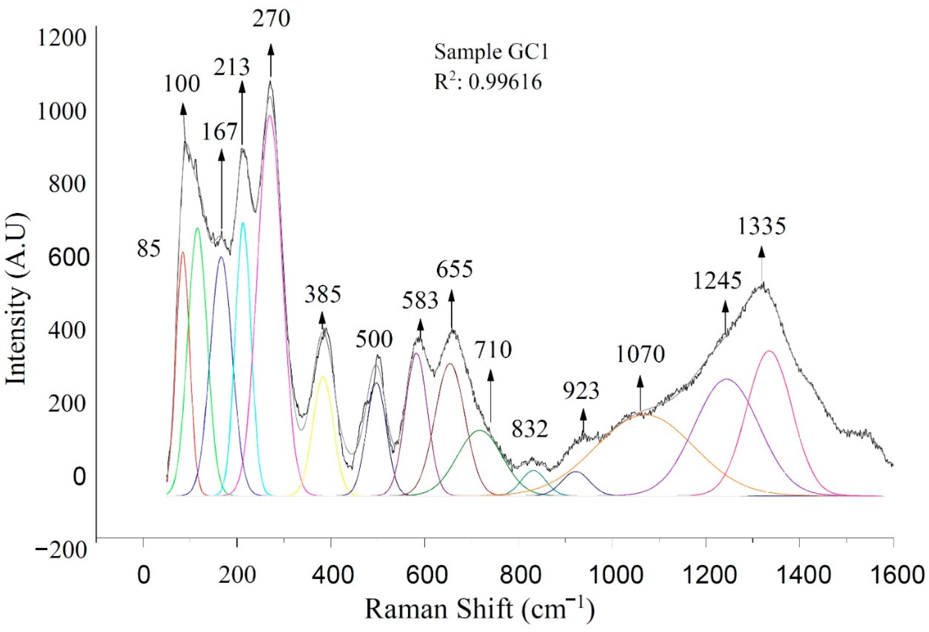
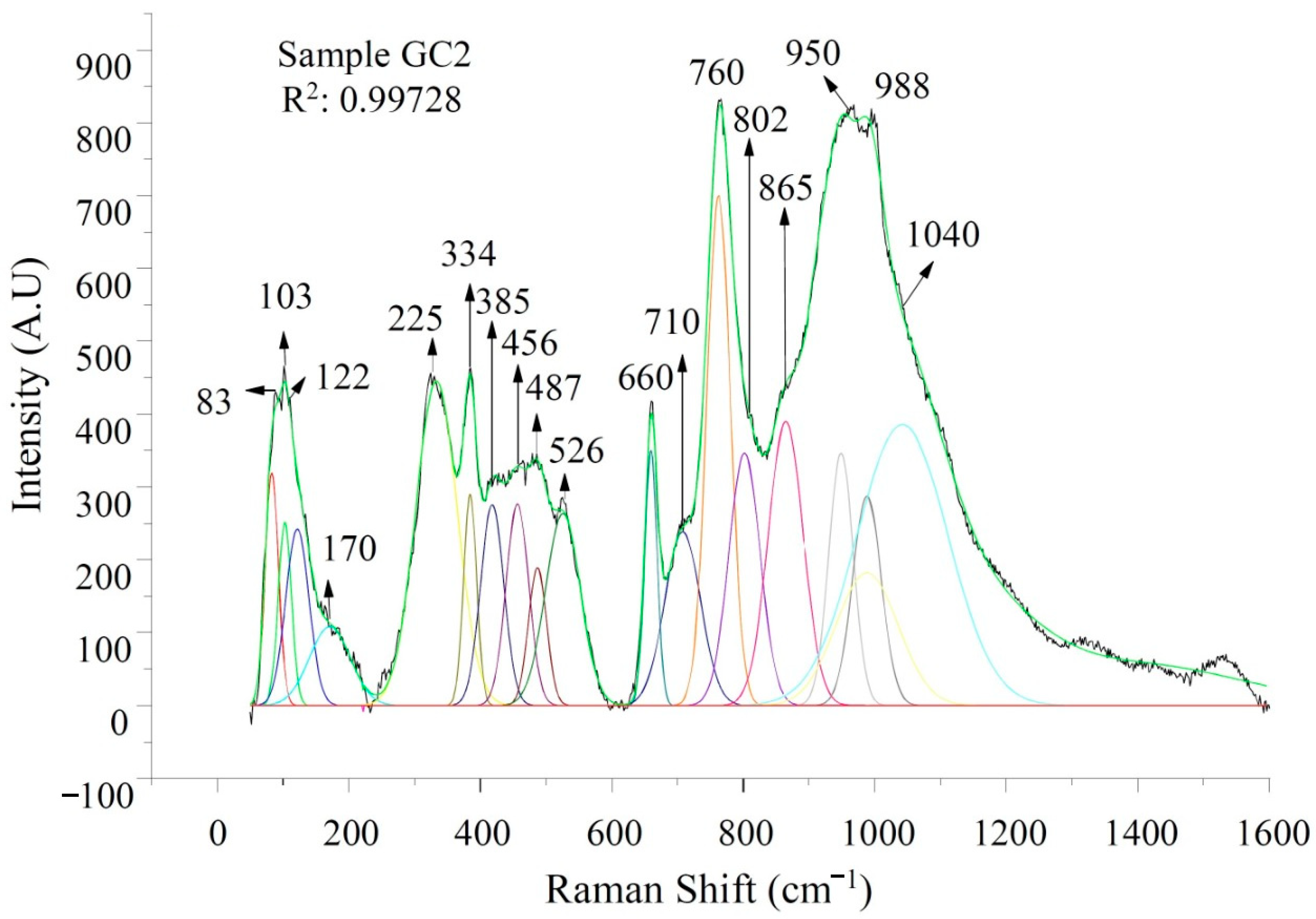
The analysis by Raman spectroscopy was carried out to verify the frequencies of bond vibrations that allow the identification of the crystalline phases in the sintered samples. The results of the Raman spectroscopy measurements are shown in Table 5.
Data reported in the literature [56,58,59,60,61] show that in Raman spectra of silicate glasses, bands associated with Q4 to Q0 species (where the index denotes the number of bridging oxygens) appear at approx. 1150 cm−1—Q4, 1050 cm−1—Q3, 1000–950 cm−1—Q2, 880 cm−1—Q1, and 850 cm−1—Q0. For the sake of clarity, the three Raman spectra obtained from the sintered materials were classified into four band groups in the 80–400, 400–650, 650–850, and 850–1500 cm−1. The bands in the range 400 to 650 cm−1 were associated with the arrangement of short-range rings of four to six members of tetrahedral SiO4 [33]. The vibrational bands along the range 650 to 850 cm−1 correspond to the Si-O-Si oxygen bridge, where there is a replacement of Si-O-Al tetrahedral structures corresponding to Al-O vibrations with coordination number 4; the region between 850 and 1400 cm−1, corresponding to vibrations of structural units Si-O-Si, where the vibrating bands are identified in the range 1000–1500 cm−1, represents typical signals in iron containing materials [33].
Structural differences are visible in the Raman spectra of the three sintered samples (GC1, GC2, and GC3), and are shown in Figure 10, Figure 11 and Figure 12. Specifically, the frequencies of bands at 83 cm−1, identified in samples GC2 and GC3, as well as the band at position 85 cm−1 of sample GC1, correspond to materials with anorthite phase [45,46]. Bands between 100 and 300 cm−1 have a greater contribution of Ca2+ ions and a small contribution of O2 in the materials in accordance with Lucena et al. [47]. The bands identified at positions 270 cm−1 in sample GC1, 225 cm−1 in sample GC2, and 272 cm−1 in sample GC3 appear to correspond to hematite [48], and the band at 385 cm−1 is consistent with magnetite, despite the fact that these phases were not detected by X-ray diffraction analysis.
An overlap of the peaks in the diffractograms (Figure 4, Figure 5 and Figure 6) could be the reason for the non-identification of such Fe containing phases, taking into account that according to the literature hematite should exhibit peaks at 2 theta 27°, 28°, 35°, and 36° [62,63] and magnetite at around 10°, 12°, 15°, 18°, and 35° [59,64].
Despite finding a variety of documents related to Raman spectroscopy results on similar materials, the information found regarding the vibrational modes related with 1070, 1245, 1320, and 1335 cm−1 signals is not clear or precise [33,46,47,51,65]. However, according to the XRD analysis, the observed vibratory bands exhibit a high correlation with the crystalline phases of anorthite and diopside, but they do not correspond with the enstatite and magnetite phases.

3.4. Bulk Density, Water Absorption, and Apparent Porosity

The density, water absorption, and apparent porosity of the glass-ceramics were experimentally measured according to the methodology described by ASTM C373 and ASTM C20. The weight of sintered GC1, GC2, and GC3 samples was measured using a balance (MODEL Kern ABS 220 4N) with a tolerance of 0.01 g. Subsequently, the samples were submerged in sufficient distilled boiling water for 5 h followed by 24 h of sowing to determine the suspended mass (S) to the nearest 0.01 g. The samples were then dried with a piece of cotton to remove excess water on the surface. The samples were weighed for the determination of saturated mass (W) [65,66]. With the data obtained, the external volume (V) in cm3 was obtained by subtracting the saturated mass from the suspended mass (V = W-S). The volume of open porosity (VOP) can be determined from the difference between saturated mass and dry mass as follows: (VOP = WD). The apparent porosity (P) was calculated as a percentage of open porosity data and volume as follows: P = (OPV/V) × 100. The bulk density (B) in g·cm−3 was determined from the ratio of dry mass (D) to external volume (V), including pores, as follows: B = D/V. An important property in glass-ceramic materials is water absorption (A), which can be expressed as a percentage of the volume ratio of open porosity and dry mass as follows: A = (OPV/D) × 100. Water impermeability was determined calculating the apparent specific gravity (T). Waterproofing can be expressed as a percentage of the ratio of dry mass to suspended mass as follows: T = D/(D − S).
The data obtained for the density, water absorption, and apparent porosity of samples GC1, GC2, and GC3 are shown in Table 6, including the averages of the values obtained from five samples of each material. The results were similar to previous research where glass-ceramic materials were obtained from industrial wastes with densities in the range of 1.6–3.2 g·cm−3 [5,22,66]. In samples GC2 and GC3, the values of the density are lower in comparison to the sample GC1, which can be correlated with a decreased content of glass cullet in the starting mixture [67]. The decrease of the density in each sample could be correlated with the amount of diopside phase present in the material (GC1: 59%, GC2: 63%, and GC3: 43%), taking into account that the density of diopside is 3.4 g·cm−3 [36]. Therefore, it is expected that the density increases or decreases according to the increase or decrease of this phase in the material [15].
The porosity and the water absorption values correlated with each other and decreased with the increase in crystallinity. The porosity and water absorption values of sample GC2 were higher than for samples GC1 and GC3, related to the degree of crystallization [23]. The porosity in the sintered materials was in the range ~22–32% (Table 6).
Water absorption affects the performance of materials, since water penetrates into larger voids due to hydrostatic pressure, affecting the degradation rate. For this research, in GC1 specimens, the water absorption is rather low (7.2%) compared to the samples GC2 (14.5%) and GC3 (12.9%). It was evident that the materials exhibited different tendencies associated with the composition. The glass cullet (55 wt.%), fly ash (35 wt.%), and slag (10 wt.%) in sample GC2 led to an increase in porosity. In general, the result obtained in this research correlated with other works in which porous glass-ceramics have been developed [12,41].

4. Conclusions

Glass-ceramics based on mixtures of fly ash, waste glass, and slag were successfully obtained via powder technology and sintering. It was possible to identify an anorthite-type crystalline phase in all samples. Other crystalline phases formed were diopside, enstatite, and augite. The results of Raman spectroscopy demonstrated the presence of chemical bonds vibrations concordant with the anorthite and diopside phases, which are characteristic of this type of materials. The successful consolidation of glass-ceramic microstructures was achieved by heat treatments at temperature between 800 and 1100 °C for 2 h. The crystal size was obtained by the Debye–Scherrer equation. The detailed characterization of the glass-ceramic materials by Rietveld refinement and Raman analysis represent and innovative aspect for the analysis of this type of industrial waste derived materials. This work demonstrated thus the possibility of obtaining glass-ceramic materials using a tailored combination of waste materials by sinter-crystallization, without using nucleating agents.

Author Contributions

Conceptualization: A.R.B. and J.A.G.C.; methodology: D.M.A.V. and N.T.; formal analysis: D.M.A.V.; investigation: D.M.A.V.; resources: D.M.A.V., A.R.B., and J.A.G.C.; data curation: D.M.A.V. and N.T.; writing—original draft preparation: D.M.A.V.; writing—review and editing: A.R.B. and J.A.G.C.; supervision: A.R.B. and J.A.G.C.; project administration: D.M.A.V.; funding acquisition: D.M.A.V. and A.R.B. All authors have read and agreed to the published version of the manuscript.

Funding

This research was funded by Government of Boyacá-Colombian and Colciencias for financial support under Call 733 (2016) and the Institute of Biomaterials, University Erlangen–Nuremberg, 91058 Erlangen, Germany.

Data Availability Statement

The authors confirm that the data supporting the findings of this study are available within the article.

Acknowledgments

The authors would like to thank the Government of Boyacá and Colciencias for financial support under Call 733 (2016).

Conflicts of Interest

The authors declare to have no conflict of interest to disclose regarding the research on this paper.

References

  1. Andreola, F.; Barbieri, L.; Lancellotti, I.; Leonelli, C.; Manfredini, T. Recycling of industrial wastes in ceramic manufacturing: State of art and glass case studies. Ceram. Int. 2016, 42, 13333–13338. [Google Scholar] [CrossRef]
  2. Chinnam, R.K.; Francis, A.A.; Will, J.; Bernardo, E.; Boccaccini, A.R. Functional glasses and glass-ceramics derived from iron rich waste and combination of industrial residues. J. Non-Cryst. Solids 2013, 365, 63–74. [Google Scholar] [CrossRef]
  3. Karayannis, V.; Moutsatsou, A.; Domopoulou, A.; Katsika, E.; Drossou, C.; Baklavaridis, A. Fired ceramics 100% from lignite fly ash and waste glass cullet mixtures. J. Build. Eng. 2017, 14, 1–6. [Google Scholar] [CrossRef]
  4. Höland, W.; Beall, G.H. Glass Ceramics Technology; The American Ceramic Society: Westerville, OH, USA, 2012. [Google Scholar]
  5. Rawlings, R.; Wu, J.; Boccaccini, A. Glass-ceramics: Their production from wastes—A Review. J. Mater. Sci. 2006, 41, 733–761. [Google Scholar] [CrossRef] [Green Version]
  6. Dhir, R.; de Brito, J.; Ghataora, G.S.; Lye, C.Q. Use of Glass Cullet in Ceramics and Other Applications. Sustain. Constr. Mater. 2018, 327–387. [Google Scholar] [CrossRef]
  7. Cao, J.; Lu, J.; Jiang, L.; Wang, Z. Sinterability, microstructure and compressive strength of porous glass-ceramics from metallurgical silicon slag and waste glass. Ceram. Int. 2009, 42, 10079–10084. [Google Scholar] [CrossRef]
  8. Clark, T.J.; Reed, J.S. Kinetic Processes Involved in the Sintering and Crystallization of Glass Powders. J. Am. Ceram. Soc. 1986, 69, 837–846. [Google Scholar] [CrossRef]
  9. Yao, Z.; Ling, T.-C.; Sarker, P.K.; Su, W.; Liu, J.; Wu, W.; Tang, J. Recycling difficult-to-treat e-waste cathode-ray-tube glass as construction and building materials: A critical review. Renew. Sustain. Energy Rev. 2018, 81, 595–604. [Google Scholar] [CrossRef]
  10. Cumpston, B.; Shadman, F.; Risbud, S. Utilization of coal-ash minerals for technological ceramics. J. Mater. Sci. 1992, 27, 1781–1784. [Google Scholar] [CrossRef]
  11. Park, Y.J.; Moon, S.O.; Heo, J. Crystalline phase control of glass ceramics obtained from sewage sludge fly ash. Ceram. Int. 2003, 29, 223–227. [Google Scholar] [CrossRef]
  12. Gao, H.T.; Liu, X.H.; Chen, J.Q.; Qi, J.L.; Wang, Y.B.; Ai, Z.R. Preparation of glass-ceramics with low density and high strength using blast furnace slag, glass fiber and water glass. Ceram. Int. 2018, 44, 6044–6053. [Google Scholar] [CrossRef]
  13. Bai, H.; Zhang, X.; Cang, D.; Zhao, L.; Wei, W. Synthesis of steel slag ceramics: Chemical composition and crystalline phases of raw materials. Int. J. Miner. Metall. Mater. 2015, 22, 325–333. [Google Scholar] [CrossRef] [Green Version]
  14. Marinova, I.; Valencia, J.S.; Navarro, E.; Carda, J.B.; Quimicer, S.A.; Onda, D. Síntesis y caracterización de esmaltes de alto índice de refracción y dureza. Qualicer 2006, 2006, 249–260. [Google Scholar]
  15. Tabit, K.; Waqif, M.; Saâdi, L. Anorthite-cordierite based binary ceramics from coal fly ash and steel slag for thermal and dielectric applications. Mater. Chem. Phys. 2020, 254, 123472. [Google Scholar] [CrossRef]
  16. Li, B.; Guo, Y.; Fang, J. Effect of crystallization temperature on glass-ceramics derived from tailings waste. J. Alloy. Compd. 2020, 838, 155503. [Google Scholar] [CrossRef]
  17. Tabit, K.; Hajjou, H.; Waqif, M.; Saâdi, L. Effect of CaO/SiO2 ratio on phase transformation and properties of anorthite-based ceramics from coal fly ash and steel slag. Ceram. Int. 2020, 46, 7550–7558. [Google Scholar] [CrossRef]
  18. Monich, P.R.; Romero, A.R.; Rambaldi, E.; Bernardo, E. Case studies of up-cycling of partially crystallized ceramic waste in highly porous glass-ceramics. Constr. Build. Mater. 2020, 261, 119971. [Google Scholar] [CrossRef]
  19. Flesoura, G.; Monich, P.R.; Alarcón, R.M.; Desideri, D.; Bernardo, E.; Vleugels, J.; Pontikes, Y. Porous glass-ceramics made from microwave vitrified municipal solid waste incinerator bottom ash. Constr. Build. Mater. 2021, 270. [Google Scholar] [CrossRef]
  20. Zhang, Z.; Wang, J.; Liu, L.; Ma, J.; Shen, B. Preparation of additive-free glass-ceramics from MSW incineration bottom ash and coal fly ash. Constr. Build. Mater. 2020, 254, 119345. [Google Scholar] [CrossRef]
  21. Jun Park, Y.; Heo, J. Conversion to glass-ceramics from glasses made by MSW incinerator fly ash for recycling. Ceram. Int. 2002, 28, 689–694. [Google Scholar] [CrossRef]
  22. Bernardo, E.; Castellan, R.; Hreglich, S. Sintered glass-ceramics from mixtures of wastes. Ceram. Int. 2007, 33, 27–33. [Google Scholar] [CrossRef]
  23. Erol, M.; Küçükbayrak, S.; Ersoy-Meriçboyu, A. Production of glass-ceramics obtained from industrial wastes by means of controlled nucleation and crystallization. Chem. Eng. J. 2007, 132, 335–343. [Google Scholar] [CrossRef]
  24. Rabelo Monich, P.; Rincon Romero, A.; Höllen, D.; Bernardo, E. Porous glass-ceramics from alkali activation and sinter-crystallization of mixtures of waste glass and residues from plasma processing of municipal solid waste. J. Clean. Prod. 2018, 188, 871–878. [Google Scholar] [CrossRef]
  25. Ayala Valderrama, D.M.; Gomez Cuaspud, J.A.; Roether, J.A.; Boccaccini, A.R. Development and characterization of glass-ceramics from combinations of slag, fly ash, and glass cullet without adding nucleating agents. Materials 2019, 12, 2032. [Google Scholar] [CrossRef] [Green Version]
  26. Toby, B.H. EXPGUI, a graphical user interface for GSAS. J. Appl. Crystallogr. 2001, 34, 210–213. [Google Scholar] [CrossRef] [Green Version]
  27. Taylor, A.; Sinclair, H. On the determination of lattice parameters by the debye-scherrer method. Proc. Phys. Soc. 1945, 57, 126–135. [Google Scholar] [CrossRef]
  28. Han, W. Glass ceramic of high hardness and fracture toughness developed from iron-rich wastes. Acta Metall. Sin. Engl. Lett. 2009, 22, 181–190. [Google Scholar] [CrossRef] [Green Version]
  29. Boccaccini, A.R.; Han, W.X.; Dimech, C.; Rawlings, R.D. Glass ceramics of high hardness and fracture toughness developed from steel fly ash. Mater. Sci. Technol. 2006, 22, 1148–1154. [Google Scholar] [CrossRef]
  30. Rozenstrauha, I.; Sosins, G.; Krage, L.; Sedmale, G. Elaboration of new ceramic composites containing glass fibre production wastes. Bol. Soc. Esp. Ceram. 2013, 52, 88–92. [Google Scholar] [CrossRef]
  31. Gralik, G.; Chinelatto, A.L.; Chinelatto, A.S.A.; Grossa, P. Effect of different sources of alumina on the microstructure and mechanical properties of the triaxial porcelain. Cerámica 2014, 60, 471–481. [Google Scholar] [CrossRef]
  32. Lara Viera, J.A. Estudio del Vitrocerámico (1 − x) LÍ2B407 − xBi2W06 (0 < x < 0.35) Usando el Método Rietveld; Universidad Autónoma de Nuevo León: San Nicolás de los Garza, Mexico, 2002. [Google Scholar]
  33. Paucar Alvarez, C.G. Vitrocerámicos con bajo Coeficiente de Expansión Térmica Obtenidos por Sinterización con Cristalización Concurrente en Partículas Vítreas de Li2O.Al2O3.XSiO2; Universidad Autónoma de Madrid: Madrid, Spain, 2016. [Google Scholar]
  34. Daniel, I.; Gillet, P.; Ghose, S. A new high-pressure phase transition in anorthite (CaAl2Si2O8) revealed by Raman spectroscopy. Am. Miner. 1995, 80, 645–648. [Google Scholar]
  35. Cheng, X.; Ke, S.; Wang, Q.; Wang, H.; Shui, A.; Liu, P. Fabrication and characterization of anorthite-based ceramic using mineral raw materials. Ceram. Int. 2012, 38, 3227–3235. [Google Scholar] [CrossRef]
  36. Ptáček, P.; Opravil, T.; Šoukal, F.; Havlica, J.; Holešinský, R. Kinetics and mechanism of formation of gehlenite, Al-Si spinel and anorthite from the mixture of kaolinite and calcite. Solid State Sci. 2013, 26, 53–58. [Google Scholar] [CrossRef]
  37. Marques, V.M.F.; Tulyaganov, D.U.; Agathopoulos, S.; Gataullin, V.K.; Kothiyal, G.P.; Ferreira, J.M.F. Low temperature synthesis of anorthite based glass-ceramics via sintering and crystallization of glass-powder compacts. J. Eur. Ceram. Soc. 2006, 26, 2503–2510. [Google Scholar] [CrossRef]
  38. Si, W.; Li, S. Crystallization kinetics of diopside glass ceramics. J. Phys. Conf. Ser. 2020, 1676. [Google Scholar] [CrossRef]
  39. Reyes Ortiz, O.J.; Camacho Tauta, J.F. Efecto del desperdicio de una siderurgica en bases y subbases granulares. Rev. Cienc. Ing. Neogranadina 2003, 13, 25–29. [Google Scholar] [CrossRef] [Green Version]
  40. Fernández Navarro, J. Constitución de los vidrios. Cons. Super. Investig. Cient. 1991, 1, 44–120. [Google Scholar]
  41. Ghosal, S.; Self, S.A. Particle size-density relation and cenosphere content of coal fly ash. Fuel 1995, 74, 522–529. [Google Scholar] [CrossRef]
  42. Liu, H.; Lu, H.; Chen, D.; Wang, H.; Xu, H.; Zhang, R. Preparation and properties of glass–ceramics derived from blast-furnace slag by a ceramic-sintering process. Ceram. Int. 2009, 35, 3181–3184. [Google Scholar] [CrossRef]
  43. Yang, M.; Guo, Z.; Deng, Y.; Xing, X.; Qiu, K.; Long, J.; Li, J. International Journal of Mineral Processing Preparation of CaO–Al2O3–SiO2 glass ceramics from coal gangue. Int. J. Miner. Process. 2012, 102–103, 112–115. [Google Scholar] [CrossRef]
  44. Amstock, J. Manual del Vidrio en la Construcción; McGraw Hill: Mexico City, Mexico, 2011. [Google Scholar]
  45. Matson, D.W.; Sharma, S.K.; Philpotts, J.A. Raman spectra of some tectosilicates and of glasses along the orthoclase-anorthite and nepheline-anorthite joins. Am. Mineral. 1986, 71, 694–704. [Google Scholar]
  46. Daniel, I.; Gillet, P.; Mcmillan, P.F.; Wolf, G.; Verhelst, M.A. High-pressure behavior of anorthite: Compression and amorphization is observed which transforms the Ii polymorph into. J. Geophys. Res. 1997, 102, 10313–10325. [Google Scholar] [CrossRef]
  47. Lucena, G.L.; de Lima, L.C.; Honório, L.M.C.; de Oliveira, A.L.M.; Tranquilim, R.L.; Longo, E.; de Souza, A.G.; Maia, A.d.S.; dos Santos, I.M.G. CaSnO3 obtained by modified Pechini method applied in the photocatalytic degradation of an azo dye. Cerámica 2017, 63, 536–541. [Google Scholar] [CrossRef]
  48. Starbird-Pérez, R.; Montero-Campos, V. Synthesis of magnetic iron oxide nanoparticles toward arsenic removal from drinking water. Tecnol. Marcha 2015, 28, 45–54. [Google Scholar]
  49. Le Parc, R.; Champagnon, B.; Dianoux, J.; Jarry, P.; Martinez, V. Anorthite and CaAl2Si2O8 glass: Low frequency Raman spectroscopy and neutron scattering. J. Non-Cryst. Solids 2003, 323, 155–161. [Google Scholar] [CrossRef]
  50. Sharma, S.K.; Simons, B.; Yoder, H.S. Raman study of anorthite, calcium Tschermak’s pyroxene, and gehlenite in crystalline and glassy states. Am. Mineral. 1983, 68, 1113–1125. [Google Scholar]
  51. Sánchez-Polo, A.; Briceño, S.; Jamett, A.; Galeas, S.; Campaña, O.; Guerrero, V.; Arroyo, C.R.; Debut, A.; Mowbray, D.J.; Zamora-Ledezma, C.; et al. An Archaeometric Characterization of Ecuadorian Pottery. Sci. Rep. 2019, 9, 2642. [Google Scholar] [CrossRef]
  52. Montoya-Quesada, E.; Villaquirán-Caicedo, M.A.; Mejía de Gutiérrez, R.; Muñoz-Saldaña, J. Effect of ZnO content on the physical, mechanical and chemical properties of glass-ceramics in the CaO–SiO2–Al2O3 system. Ceram. Int. 2020, 46, 4322–4328. [Google Scholar] [CrossRef]
  53. Lu, S.G.; Kwok, K.W.; Chan, H.L.W.; Choy, C.L. Structural and electrical properties of BaTi4O9 microwa v e ceramics incorporated with glass phase. Mater. Sci. Eng. B 2003, 99, 6–9. [Google Scholar] [CrossRef]
  54. Solids, N.; Friebele, J.; Calcium, I. Glass formation and thermal properties of low-silica calcium aluminosilicate glasses. J. Non-Cryst. Solids 1990, 126, 209–215. [Google Scholar]
  55. Urquijo, J.P.; Casanova, H.; Morales, A.L. Engineering Iron oxide nanoparticles for biomedicine and bioengineering applications Diseño de nanopartículas magnéticas para aplicaciones en biomedicina y bioingeniería. Rev. Fac. Ing. Univ. Antoquia 2014, 71, 230–243. Available online: http://www.scielo.org.co/pdf/rfiua/n71/n71a21.pdf (accessed on 7 May 2021).
  56. Partyka, J. Effect of BaO ratio on the structure of glass–ceramic composite materials from the SiO2–Al2O3–Na2O–K2O–CaO system. Ceram. Int. 2015, 41, 9337–9343. [Google Scholar] [CrossRef]
  57. Jerez Delgado, D. Crecimiento y Caracterización de Micro y Nanoestructuras de Óxidos de Hierro y Estaño/Growth and Characterization of Iron and Tin Oxides Micro and Nanostructures. 2012. Available online: https://eprints.ucm.es/id/eprint/16499/ (accessed on 7 May 2021).
  58. Partyka, J.; Leśniak, M. Raman and infrared spectroscopy study on structure and microstructure of glass-ceramic materials from SiO2-Al2O3-Na2O-K2O-CaO system modified by variable molar ratio of SiO2/Al2O3. Spectrochim. Acta Part A Mol. Biomol. Spectrosc. 2016, 152, 82–91. [Google Scholar] [CrossRef] [PubMed]
  59. Fan, W.D.; Yang, Q.W.; Guo, B.; Liu, B.; Zhang, S.G. Crystallization mechanism of glass-ceramics prepared from stainless steel slag. Rare Met. 2018, 37, 413–420. [Google Scholar] [CrossRef]
  60. Agathopoulos, S.; Tulyaganov, D.U.; Ventura, J.M.G.; Kannan, S. Structural analysis and devitrification of glasses based on the CaO–MgO–SiO2 system with B2O3, Na2O, CaF2 and P2O5 additives. J. Non-Cryst. Solids 2006, 352, 322–328. [Google Scholar] [CrossRef]
  61. Chuvaeva, T.I.; Dymshits, O.S.; Petrov, V.I.; Tsenter, M.Y. Low-frequency Raman scattering of magnesium aluminosilicate glasses and glass-ceramics. J. Non-Cryst. Solids 2001, 282, 306–316. [Google Scholar] [CrossRef]
  62. Blake, R.L.; Hessevic, R.E.; Zoltai, K.T.; Finger, L.W. Refinement of the Hematite Structure. Am. Mineral. 1966, 51, 123–129. [Google Scholar]
  63. INEGI La Industria Minera Ampliada. p. 117, 2016. Available online: https://www.inegi.org.mx/contenido/productos/prod_serv/contenidos/espanol/bvinegi/productos/censos/economicos/2009/mineria/Mono_Industria_Minera.pdf (accessed on 7 May 2021).
  64. Haavik, C.; Stølen, S.; Fjellvåg, H.; Hanfland, M.; Häusermann, D. Equation of state of magnetite and its high-pressure modification: Thermodynamics of the Fe-O system at high pressure. Am. Mineral. 2000, 85, 514–523. [Google Scholar] [CrossRef]
  65. ASTM C373-88—Standard Test Method for Water Absorption, Bulk Density, Apparent Porosity, and Apparent Specific Gravity of Fired Whiteware Products; ASTM International: Montgomery, PA, USA, 2006; pp. 1–2.
  66. Nebot Diaz, I.; Marcharl, M.; Iran, M.; Carba, B.J. Nuevas Tecnologías Para el Sector Cerámico; Universitat Jaume: Valencia, Spain, 2000. [Google Scholar]
  67. Radeva, V. Adaptando el método de arquímedes para determinar las densidades y porosidad de muestras pequeñas de cerámica. Cienc. Soc. 2006, XXXI, 565–585. [Google Scholar] [CrossRef]
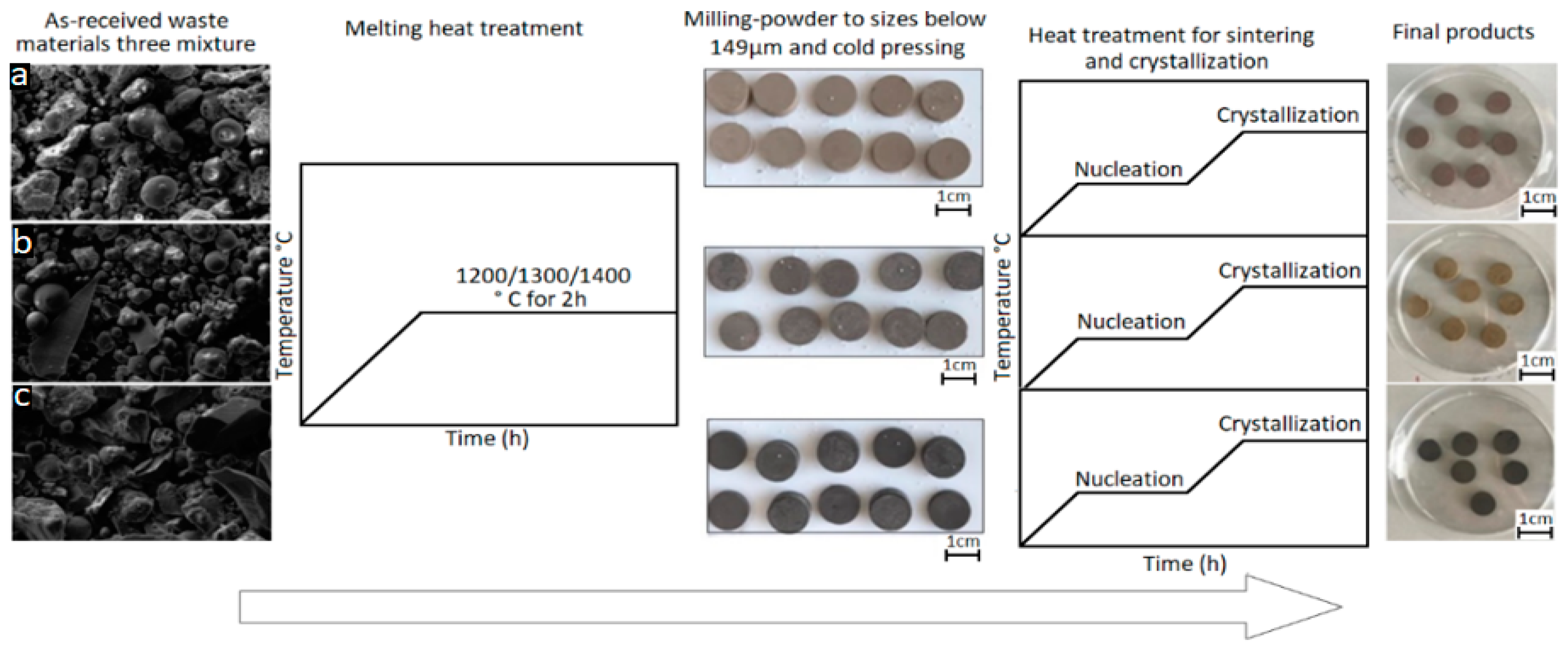
Figure 1. Scheme of the production of glass-ceramic materials obtained by sintering vitreous powders: (a) Mixture GC1, (b) Mixture GC2, and (c) Mixture GC3.
Constrmater 01 00004 g001
Figure 2. X-ray diffraction patterns of mixtures treated at 1200/1300/1400 °C for 2 h to obtain amorphous materials: (a) Sample GC1, (b) Sample GC2, and (c) Sample GC3.
Constrmater 01 00004 g002
Figure 3. Differential thermal analysis profiles of GC1, GC2, and GC3 samples.
Constrmater 01 00004 g003
Figure 4. X-ray diffraction patterns of sample GC1 obtained at T1: 950 °C/2 h and T2: 1100 °C/2 h (see Table 2).
Constrmater 01 00004 g004
Figure 5. X-ray diffraction patterns of sample GC2 obtained at T1: 800 °C for 2 h and T2: 1050 °C for 2 h (see Table 2).
Constrmater 01 00004 g005
Figure 6. X-ray diffraction patterns of GC3 sample obtained at T1: 850 °C for 2 h and T2: 1100 °C for 2 h (see Table 2).
Constrmater 01 00004 g006
Figure 7. SEM images and EDS results of sample GC1: (a) prior to thermal treatment, (b) after thermal treatment at 1300 °C and subsequently the milling process, (c) the surface of a pellet after the sintering and crystallization process, and (d) EDS spectrum and elemental mapping of image (c).
Constrmater 01 00004 g007
Figure 8. SEM images and EDS results of sample GC2: (a) prior to thermal treatment, (b) after thermal treatment at 1300 °C and subsequently the milling process, (c) the surface of a pellet after the sintering and crystallization process, and (d) EDS spectrum and elemental mapping of image (c).
Constrmater 01 00004 g008
Figure 9. SEM images and EDS results of sample GC3: (a) prior to thermal treatment, (b) after thermal treatment at 1300 °C and subsequently the milling process, (c) surface of a pellet after sintering and crystallization, and (d) EDS spectrum and elemental mapping of image (c).
Constrmater 01 00004 g009
Figure 10. Raman spectrum of the sample GC1 after sintering and crystallization.
Constrmater 01 00004 g010
Figure 11. Raman spectrum of the sample GC2 after sintering and crystallization.
Constrmater 01 00004 g011
Figure 12. Raman spectrum of the sample GC3 after sintering and crystallization.
Constrmater 01 00004 g012
Table 1. Composition (% weight) of raw materials and chemical compositions (mole percent) of samples developed in this study.
Samplewt.%Composition of Mixtures Investigated (mole %).
SlagFly AshGlass CulletNa2OMgOAl2O3SiO2SO3K2OCaOTiO2Fe2O3MnOther
GC11070203.6271.8513.6466.30.80.77.11.093.9240.70.285
GC21035554.9143.388.16166.40.60.4120.642.8280.70.227
GC35535101.8133.1211.2446.90.70.5201.039.6863.70.927
Table 2. Parameters refer to the sintering of the pellets.
SampleNucleation TemperaturaCrystallization Temperature
GC1950 °C for 2 h1100 °C for 2 h
GC2800 °C for 2 h1050 °C for 2 h
GC3850 °C for 2 h1100 °C for 2 h
Table 3. Quantification of crystalline phases, their chemical formulas and lattice parameters of GC1, GC2, and GC3 samples.
Crystalline PhaseChemical FormulaLattice Parameters (Å)Composition Percentage (%) of Sample
abcGC1GC2GC3
Anorthite(O64Ca8Si16Al16)8.17312.86912.894596343
Diopside(Mg4 Ca4 Si8 O24)9.6818.8495.2187155
Enstatite(Mg16Si16O48)5.18118.2518.81471621
Augite(Na0,36Ca2,46Mg3,61Fe0,84Al1,37Ti0,08Si7,28O24)9.6998.8445.27227631
Table 4. Crystallite size of the three samples GC1, GC2, and GC3.
Sample2ϴL2ϴHϴBB(rad)t (nm)
GC123.0323.6823.4011.6980.360.0060.59
GC227.3627.4827.5713.7850.210.0031.91
GC327.3927.8727.6913.8450.300.0051.60
2ϴL: Left grain limit
2ϴH: Right side grade limit
2ϴ: Midpoint of grain size
t = (kλ)/B(ϴ)·Cos ϴ
ϴ = 2ϴ/2
B = 2ϴH−2ϴL
B(rad) = (B·π)/180
Table 5. Raman spectroscopy results for samples GC1, GC2, and GC3.
Band Position
(cm−1)
Possible Bond or Crystalline PhaseRef.
83,85Anorthite pase[45,46]
100–300Vibrations with a greater contribution of Ca2+ atoms and a small contribution of O2[47]
225,270,272Hematite[48]
326Anorthite[45,46]
385Magnetite[48]
473–482Si-O-Si systems with bridge oxygen and Al-O vibrations with coordination number 4[33]
500The movements of oxygen atoms along the union angles between T-O-T[33]
583Bending vibrations Si-O-Si, T-O-T[49]
526,660,750Characteristic bands of ceramic-ceramic materials[45,46]
660Si-O-Si vibrations in Q2 units related to the diopside phase[50,51]
611,705,872Stretching calcium carbonates [51,52]
710Indicates that there are aluminum-oxygen octahedrals[53,54]
712Pure magnetite, located in the band 710 cm−1 in this study[49,55,56]
760Characteristic bands of ceramic-ceramic materials - characteristic vibration of Si[45,46]
799FeO vibrations[51]
950Diopside phase given by Si/O vibrations (Q2) located in the band 958 cm-1 in this study[48,57]
958Diopside - Si/O Vibrations (Q2)[49,50]
997Si-O-Si vibrational modes[51]
1040Si-O-Al vibrations.[49,50]
Table 6. Density and porosity calculations of the three samples GC1, GC2, and GC3.
SampleDry Mass (D)(g)Saturated Mass (W) (g)Suspended Mass (S)(g)Density (B) (g·cm−3)Water Absorption (A) (%)Apparent Porosity (P) (%)
GC10.73.02.43.17.222.3
GC21.33.12.52.214.531.7
GC31.93.42.72.312.930.2
Publisher’s Note: MDPI stays neutral with regard to jurisdictional claims in published maps and institutional affiliations.