Abstract
This paper provides a five-year performance evaluation of an application of geogrid reinforcement in low-volume unpaved roads using dynamic cone penetrometer (DCP), plate load tests (PLT), and roadway sensing method. A Forest Service unpaved road located in northern Arizona, USA, exhibited severe deterioration on the surface, creating an unsafe traffic environment for vehicles. A total of four structural sections (1–4; 4.3 m wide) were installed in the 40 m long test area. One additional section of existing subgrade/roadbed with native soil adjacent to the test sections was used for comparison purposes. The project was originally completed in November 2015, followed by five annual field visits to observe surface conditions of the five test sections. Based on DCP and PLT results (both conducted in 2015), and roadway sensing tests conducted in 2020, the section made of 30 cm thick aggregate with one geogrid layer appeared to have a better capacity for resisting traffic loading as compared with the other four sections. This paper concludes that, from a long-term point of view, the geogrid reinforcement improves the capacity of the unpaved roads, with significantly reduced rutting and damage from both roadway traffic loads and weathering effects.
1. Introduction
Unpaved roads are common in less developed portions of the world and rural areas. Most Forest Service roads in Northern Arizona, USA, are low-volume and unpaved. Surrounded by Coconino National Forest in Northern Arizona, Flagstaff has an elevation of 2250 m, with the local mountains reaching over 3660 m. The local area is subject to approximately 200–250 freeze/thaw cycles per year and experiences significant snow precipitation in an average winter. Summers are moderate, with a monsoon season that typically stretches from July to September. These weather conditions have caused unpaved roads to deteriorate, creating an unsafe travelling environment for vehicles. With a limited budget at the National Forest District Office, it is extremely difficult for district engineers to maintain unpaved roads in a good condition, particularly in areas with weak and unstable subgrades and roadways, making routine maintenance a challenging task. One solution is to install geogrid reinforcement within the soil to strengthen its capacity for withstanding low-temperature variations and traffic loading. The potential for geogrids to reduce maintenance and initial construction costs, particularly in areas with weak and unstable subgrades and roadways, makes this an appealing investigation. This paper presents the implementation and results of geogrid-reinforced test roadway sections on an unpaved Forest Service Road located near Flagstaff, AZ. The geogrid-reinforced soil project was installed in the November of 2015, and has experienced five full winter seasons that have enabled engineers to assess its effectiveness and capacity for use in forest service roads across the Northern region of Arizona. This paper presents the five-year performance evaluation of geogrid reinforcement in unpaved roads and provides recommendations for local authorities so that they can better design and maintain unpaved roads within their jurisdictional areas.
In the early 1990s, Haas et al. [1] started a laboratory investigation on the effectiveness of geogrids in the improvement of granular base in flexible pavements and concluded that geogrid reinforcement can be highly effective in reinforcing the granular base material and thereby can extend the life of a structure. Since then, many studies on geogrids and geotextiles have been performed to help advance design of unpaved roads [2,3,4,5,6]. Cuelho et al. [7] conducted a field test with a focus on the effectiveness of woven geosynthetic and non-woven geogrid products in subgrade stabilization. The results indicated that the poorest performance was observed in the three types of non-woven geogrids. However, since the manufacturing technology of geogrids has been improved recently, further research work is needed to evaluate the performance of geogrids in soil improvements. There are numerous design methods for geogrid/geotextile-reinforced unpaved roads, but two of the most prevalent are the Giroud–Han [8] Design Method and the Army Corps of Engineers (COE, 2003) Method [9,10]. The COE approach calculates a subgrade bearing capacity based on shear strength of the soil as well as on bearing capacity factors that account for the added strengths of geotextiles or geogrids. Design charts based on empirical data are then used to determine aggregate thicknesses [9]. The Giroud–Han Method combines a mechanistic bearing capacity approach with empirical data gathered from field tests. This method utilizes the aperture stability modulus, a measure of in-plane stiffness against torsional bending, as the governing geogrid property [8,10,11]. Current engineering practice in pavement/roadway design is moving towards mechanistic–empirical (M100 E) design methods, with Perkins et al. [12] using an M-E approach to model geosynthetic-reinforced unpaved roads. Geogrids reinforce the roadway structural section through three primary mechanisms: lateral restraint, improved bearing capacity, and tensioned membrane effects. Improved bearing capacity can be achieved with the addition of the geogrid. The addition of the geogrid reduces the shear stresses on the subgrade and thus changes the failure mode from shear failure to general bearing failure. While not necessarily increasing the actual bearing capacity of the subgrade, this shift in failure modes provides significant benefits [8,9,10]. Tensioned membrane effects are typically seen with an increased deformation in geotextiles, but as the geogrid is pre-strained in the manufacturing process, tensile capacity can be mobilized with decreased strains [8]. Lateral restraint is the primary mechanism through which the geogrid increases the capacity of the unpaved roadway. Lateral restraint causes a mechanical interlock between the aggregate base (AB) course material which increases stiffness, better distributes stresses, and decreases surface rutting [8]. This increase in stiffness associated with aggregate interlock is well-studied and has even been incorporated into a mechanistic pavement analysis by Kwon and Tutumluer [13]. Many studies have been conducted comparing the effects of geotextiles and geogrid, including Zhang and Hurta [14] and Tabatabaei and Rahman [15]. Full-scale tests have been performed, such as Tang et al. who investigated geosynthetics under full-scale truck axle loads, and Hufenus et al. who performed a full-scale field test on unpaved roads over soft subgrade [16,17,18]. Plate load testing was used to quantify the benefits of geosynthetic reinforcement by Abu-Farsakh et al. [19]. Al-Qadi and Appea completed an eight-year long-term study of a paved road that used geosynthetics for reinforcement at the subgrade-base interface [20]. A number of numerical analyses and modelings of geo-reinforced soils have been studied to understand the response of soil reinforcements under the action of pullout loading, as well as to model the mechanical behavior of the interface between geogrid and soil materials [21,22,23]. Ying et al. [24] studied the interparticle locking in reinforcement structures under traffic, seismic, and other types of cyclic loadings and indicated that the shear stress increased and the vertical displacement decreased with an increasing amplitude of cyclic normal loading. While a lot of research has been conducted in the evaluation of geogrid reinforcements in the improvement of soil beds, continued research on climatic effects and the long-term performance of installed sections can advance the current understanding and refine design and maintenance guidelines. This is particularly important where local climatic or soil conditions suggest additional considerations are necessary. Based on a report by geotechtools.org, the cost for geosynthetics range from 3 USD/m2 to 15 USD/m2 while the granular materials used for embankment construction range from 5 USD/m2 to 20 USD/m2 [25]. While design principles for unpaved roads vary depending on geographic locations and climatic regions, none of the previous research has been specifically focused on the long-term performance of geogrid reinforcement in unpaved roads at higher elevation. Thus, this paper presents a geogrid-reinforced design evaluation using a Forest Service Road as a five-year case study to demonstrate methods that could provide better design options under the local climatic and traffic conditions in Northern Arizona.
2. Soil Properties on Project Site
After discussions with engineers at the National Forest Service in Flagstaff, AZ, a Forest Service Road near Marshall Lake, which is south and east of Flagstaff, AZ, was selected for the test site due to severe ruts and significant deterioration, and evidence of a past failed geotextile installation along this roadway section (Figure 1). This road provides access to a portion of the Arizona Trail and is closed by the Forest Service in the winter. A full geotechnical investigation was performed to gather and quantify soil properties for the engineering design of the geogrid reinforcement. Soil borings up to 91 cm in depth were conducted at 15 m intervals along the test section. Undisturbed ring samples, bulk samples, and auger samples were obtained and tested. Tests including Sieve Analysis/Plasticity Index, Moisture Content, Moisture Density Relations, Swell, Direct Shear, and California Bearing Ratio (CBR) were performed by technicians in the Materials Lab housed in Speedie and Associates Inc. in Flagstaff, AZ. Based on the report, lab testing classified the subgrade as a lean/fat clay with subordinate amounts of sand. The CBR tests using the American Society for Testing and Materials (ASTM) D1183 [26] standard returned a CBR value of 2. The volumetric properties of the soil based on the lab report are shown in Table 1 including the standards used for each test.
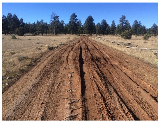
Figure 1.
Test site prior to installation in November 2015.

Table 1.
Soil test results.
3. Geogrid Design
Structural section design was accomplished using SpectraPave4 Pro based on the Giroud–Han Design Method [8,10], which is a mechanistic–empirical approach. This method combines standard bearing capacity theory with data obtained from field and laboratory testing. The only property of the geogrid used that is considered in this design method is the aperture stability modulus (ASM) of the geogrid. ASM measures the in-plane stiffness of the geogrid reinforcement by quantifying the torsional load required to twist the grid through a specific in-plane angular distortion [11]. ASM is an attempt to measure the combined effects of tensile modulus and junction strength, and is determined through the American Society for Testing and Materials (ASTM) D7864 standard [31]. After running the software under the support from the geogrid supplier, outputs from SpectraPave4 Pro indicated an unreinforced section requirement of 33 cm of aggregate base (AB). A section reinforced with the TX140 geogrid required 15 cm AB for the same designed capacity. Thus, a thickness of 15 cm AB plus a layer of geogrid is a minimum requirement for the design. Four test sections were selected (4.5 m wide and 10 m long, each). Additionally, a section of existing subgrade with native soil was preserved next to Section 4 for comparison purposes. The information of each section was explained below and shown in Table 2 and Table 3.

Table 2.
Design information of test sections.

Table 3.
Properties of materials.
3.1. Construction of the Experimental Road
Installation of the four sections was accomplished using a grader and a front-end loader. The roadway surface was excavated 15 cm to 30 cm to allow for the installation thickness of aggregate base (Figure 2). The TX140 geogrid was installed at the interface between the subgrade and the AB. For the 30 cm section with two layers of grid, the second layer was installed at the midpoint of the AB thickness. AB was placed in regular lifts to reach the final grade. The sections were wheel-compacted by the installation equipment and a 2-ton vibratory roller. Due to the remote location, moisture conditioning of the AB was not possible. Nuclear density testing following installation was performed and the results indicated that a compaction of 96% to 99% was achieved according to the ASTM D698 standard: Standard Test Methods for Laboratory Compaction Characteristics of Soil Using Standard Effort [30].
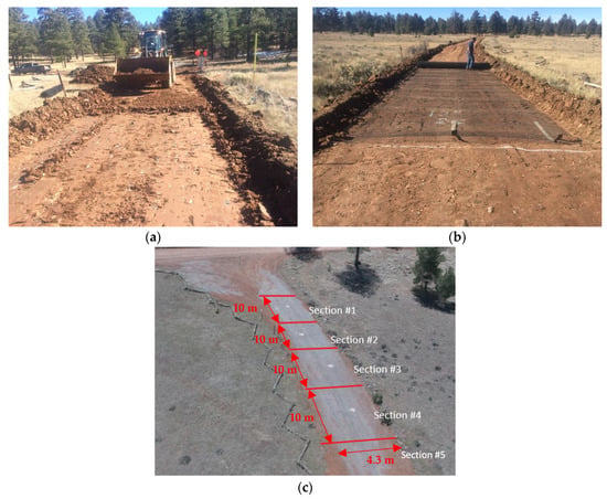
Figure 2.
Construction of geogrid-reinforced unpaved road: (a) excavation of test sections; (b) installation of geogrid reinforcement; (c) drone phone of completion of geogrid installation.
3.2. Field Testing
Following installation, dynamic cone penetrometer (DCP) and plate load testing (PLT) were conducted to quantify the performance of the installed sections. The DCP Test provides a measure of the soil’s resistance to penetration. The test was conducted by lifting a metal cone into the ground by repeatedly striking it with an 8 Kg weight that was dropped from a distance of 57.5 cm. The penetration resistance of the DCP cone was measured after each drop, and measured and counted as it penetrated up to 150 cm below the ground surface. Multiple DCP tests were conducted on each experiment section. One plate load test was performed in each section and one plate load test was conducted on the existing roadbed with native soils for improvement comparison purposes. For the plate load test, a 15-ton loaded C7500 dump truck was used as the reaction frame with a loading point located under the midsection of the truck frame (Figure 3). The PLT test procedure was briefly summarized as follows:
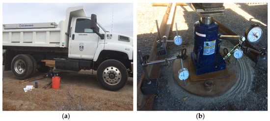
Figure 3.
Plate load testing setup: (a) 15-ton loaded C7500 dump truck; (b) steel load plate and gauges.
- (1)
- Three dial gauges were placed on a 45 cm diameter and 2.5 cm thick steel plate at diagonal corners of the plate to record the settlement.
- (2)
- An initial load of 7 KPa was applied and released before the actual loading started. The initial readings were noted.
- (3)
- The load was then applied through the hydraulic jack and increased slowly to avoid any interruption. The increment was generally at an interval of 0.5 kN. The applied load and its corresponding settlement were recorded from the pressure gauge.
4. Results and Discussion
All DCP and PLT results can be found in Table 4, Figure 4 and Figure 5. Results of the DCP field testing show significant improvements in the CBR values of the roadway. CBR values increased from 7 for the roadbed with native soils (Section 5) to 40–50 for the 15 cm section (Section 1) and as high as 80 for the two layers of grid section (Section 3). PLT results also indicate that resilient modulus increased from 73.9 MPa in the existing subgrade/roadbed to a high of 390.7 MPa in Section 3. A modulus of subgrade reaction reveals mechanistic characteristics of soil foundation, in support of pavement design. PLT results also indicate that the modulus of subgrade reaction has been substantially increased from a very poor condition of 15.3 MN/m3 [31] in the existing subgrade/roadbed to a very good condition of 169 MN/m3 [31]. The maximum settlement (3.5 mm) from PLT is noticed in Section 1 (15 cm plus one layer) while the minimum settlement (2.1 mm) is observed in Sections 3 (two layers of geogrid section plus 30 cm ABC) and 4 (30 cm ABC). Note that Section 5 represents the comparison group as it is the original soil without any treatments (geogrid reinforcement or ABC compaction).

Table 4.
Test sections and results.
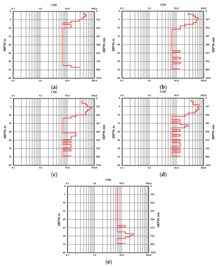
Figure 4.
Results of DCP tests from (a) Section 1; (b) Section 2; (c) Section 3; (d) Section 4; (e) Section 5.
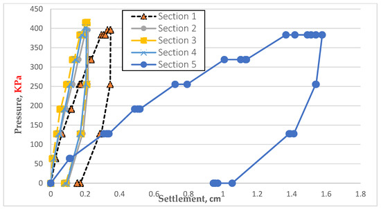
Figure 5.
Plate load test results.
4.1. Field Observation
The geogrid project was installed in the middle of November 2015, immediately prior to a winter storm that blasted through Northern Arizona. To date, the test sections have experienced seven winter seasons. Four field observations have been scheduled to monitor the geogrid-reinforced road conditions, as shown in Figure 6. The most recent field visit was scheduled for May 2020, five years after the geogrid installation. Based on the field observations, the surface of the geogrid-reinforced road was maintained in great condition with no rutting or pothole distress observed along the experimental road test section (Figure 6). However, significant rutting, potholes, and crack distress issues on Section 5 (control section: native soil) have been increasingly observed. Those substantial deformations have raised concerns for vehicle safety and have a negative impact on passenger travelling. To further investigate the effectiveness of geogrid reinforcement in soil improvement, a performance evaluation is still needed to quantitatively provide useful results and comparison between the four different geogrid sections and the control section.
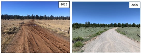
Figure 6.
Five-year comparison of geogrid-reinforced soil improvements before and after geogrid installation.
4.2. Performance Evaluation (Sensing Technology): Five Years after Installation
Five years after completion of the geogrid installation in 2015, local professionals along with government organizations are interested in how effective the geogrid reinforcement installed in unpaved roads could be at making the travel experience more comfortable than ever. As the test site is on a national forest road, the travel experience in terms of comfort level is a better indication for local governments for evaluating the effectiveness of geogrid reinforcement in unpaved roads. In this regard, a vehicle-based sensing test turned out to be a better field test for providing information related to the rough condition of road surfaces of the five test sections. Therefore, a road sensing test was performed in the middle of May 2020. Vehicle-based sensing method has been widely used to detect pavement conditions, smooth and rough, on highways. The entire testing procedure can be referred to Ho et al. [32], with the work conducted by their research team, so the details of sensing process are neglected in the paper. Three sensing tests while travelling on the five test sections were performed and vibration data were collected. Since the vibration values in the three directions X, Y, and Z were obtained, the total magnitude (M, resultant) calculated from the squired root of accelerations along axes X, Y, and Z was used to determine the unpaved road condition and it was expressed in Equation (1) as:
An example of vibration responses (M) against time in Test 1 is plotted in Figure 7. Note that the time of each section spanned about five seconds and times that spanned between 20-27 seconds were attributed to Section 5. As can be seen in Figure 7, the accelerations of gravity versus time made it difficult to compare the rough conditions of the five sections. Therefore, another approach, converting an acceleration into a displacement by a double integral and changing a second in the time domain to a distance by an integral in the horizontal axis, was implemented. The results of this conversion are shown in Figure 8, where the vertical displacements can be used to quantify the rough conditions of the five test sections. When travelling through the five testing sections, drivers might experience discomfort based on the various surface conditions of each section. To further compare the “bumpy” conditions of the five test sections, a differential displacement between the maximum and minimum magnitudes (i.e., the peak and the bottom values) was calculated. A differential vertical displacement can be seen as how rough (bumpy) the experience would be for road users when traveling along the surface. Particularly if a roadway has more ruts from the combination of traffic and weathering loads, a significant differential displacement can be measured that would indicate which section would have more resistance to traffic loads. It is also a better way for local authorities to review the surface conditions of the five sections. Figure 9 illustrates differential measurements of the five sections calculated from the three sensing tests, and the average differential displacements of the five sections are depicted in Table 5. The results also offer insightful information in terms of field performance of the five test sections subject to the combined traffic and climate effect in the past five years.
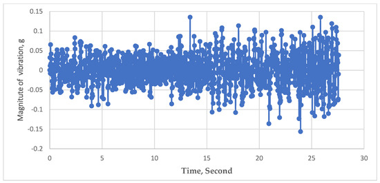
Figure 7.
Raw vibration data from Test 1.
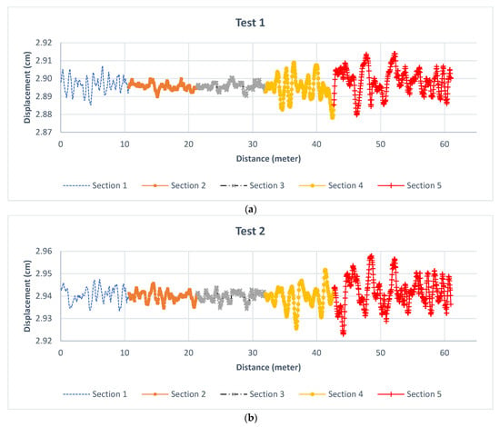
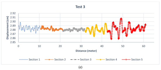
Figure 8.
Displacement versus distance analyzed from (a) Test 1; (b) Test 2; (c) Test 3 data.
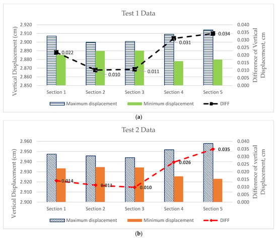
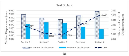
Figure 9.
Differential responses from (a) Test 1; (b) Test 2; (c) Test 3 on the five sections. Note: DIFF represents the difference between the peak and the bottom values.

Table 5.
Average Differential Displacement of the Five Sections.
It should be noted that the differential displacement is completely independent for all five sections as the thickness of each section varies, so the performance of each section can be compared. As can be seen in Figure 9 and Table 5, Sections 2 and 3 still maintain better field performance as compared with the other three Sections 1, 4, and 5, provided that the differential vibration magnitude was in a range with 0.01 cm being the least “bumpy” condition. The findings also indicate an interesting observation. Even though Sections 2 and 3 have the same thickness (30 cm), Section 2 (30 cm: one geogrid layer) exhibited almost the same differential displacement as Section 3 (30 cm: two layers) (i.e., 0.011 cm versus 0.010 cm). In other words, for expenditure/budget purposes, the design of Section 2 should be sufficient to sustain traffic and weathering loading without significant surface displacement and drivers who travel through Section 2 should not have an obvious level of discomfort. Another interesting observation is that the addition of one more geogrid in the same layer (i.e., Section 3) would not have an increased beneficial effect. In comparison with Section 1 (15 cm: one layer) and Section 4 (30 cm with ABC), an interesting observation is found. If we recall the maximum settlements from the PLT test in 2015, Section 1 actually had the highest settlement (3.5 mm) compared with Section 4 (2.1 mm). After five years, the differential displacement of Section 1 (0.021 cm) has been decreasing against that of Section 4 (0.03 cm), showing a significant improvement on the field performance. The findings indicate that even though Section 1 is less thick (15 cm) than Section 4 (30 cm), the use of the geogrid has demonstrated its ability to reinforce surrounding aggregate to form a stronger roadbed for carrying traffic loads as well as sustaining weathering conditions over the past years. In general, from a long-term point of view, the effectiveness of geogrid reinforcement in the capacity of unpaved roads is considered significant based on the test results of the years 2015 and 2020.
5. Conclusions
Based on the results of the in-situ study and field tests, along with the five-year field observations and performance evaluations, this paper has the following conclusions:
- From a long-term point of view, the use of geogrid reinforcement in unpaved roads has demonstrated its ability to provide a better road service quality for road users.
- Based on PLT results, the installed geogrid sections show dramatic reductions in deflections under loading and increased modulus of resilient and subgrade reaction values.
- In comparison with the results conducted in years 2015 and 2020, the findings show that even though Section 1 is less thick (15 cm: one geogrid layer) than Section 4 (30 cm ABC without the geogrid), the use of the geogrid has demonstrated its ability to reinforce surrounding aggregate to form a stronger roadbed to carry traffic loads as well as sustain weathering conditions over the past years.
- After experiencing five years of winter seasons, both Sections 2 (30 cm: one geogrid layer) and 3 (30 cm: two geogrid layers) show the best resistance to traffic loads and weathering conditions. It is recommended that a section consisting of a 30 cm (one layer) geogrid can be used for strength improvements of unpaved roads.
- From a long-term point of view, the effectiveness of geogrid reinforcement on the stabilization of unpaved roads is considered significant.
- Factors such as the thickness of ABC and drainage conditions that might have an impact on the durability and performance of geogrid-reinforced soil beds are recommended for future research.
Author Contributions
Conceptualization, C.-H.H., J.D. and D.Z.; methodology, C.-H.H. and J.D.; software, C.-H.H., J.D. and D.Z.; validation, C.-H.H., J.D. and D.Z.; formal analysis, C.-H.H., J.D. and D.Z.; investigation, C.-H.H. and J.D.; resources, C.-H.H. and J.D.; data curation, C.-H.H., J.D. and D.Z.; writing—original draft preparation, C.-H.H.; writing—review and editing, C.-H.H. and J.D.; visualization, C.-H.H., J.D. and D.Z.; supervision, C.-H.H.; project administration, C.-H.H. and J.D.; funding acquisition, C.-H.H. and J.D. All authors have read and agreed to the published version of the manuscript.
Funding
This research received no external funding.
Data Availability Statement
The data collected from the project are available upon request and reviewed by the authors.
Acknowledgments
This project would not have been possible without generous support from: AZ Materials, US Forest Service, Tensar International Corporation, NAU Facility Services, and Speedie and Associates, Inc. The authors express their gratitude to the above sponsors and supports.
Conflicts of Interest
The authors declare no conflict of interest.
References
- Haas, R.; Walls, J.; Carrol, R.G. Geogrid Reinforcement of Granular Bases Flexible Pavements. J. Transp. Res. Rec. 1988, 1188, 19–27. [Google Scholar]
- Chu, J.; Bo, M.W.; Choa, V. Improvement of ultra soft soil using prefabricated vertical drains. Geotext. Geomembr. 2006, 24, 339–348. [Google Scholar] [CrossRef]
- Li, A.L.; Rowe, R.K. Effects of viscous behaviour of geosynthetic reinforcement and foundation soils on embankment performance. Geotext. Geomembr. 2008, 26, 317–334. [Google Scholar]
- Gniel, J.; Bouazza, A. Improvement of soft soils using geogrid encased stone columns. Geotext. Geomembr. 2009, 27, 167–175. [Google Scholar] [CrossRef]
- Gniel, J.; Bouazza, A. Construction of geogrid encased stone columns: A new proposal based on laboratory testing. Geotext. Geomembr. 2010, 28, 108–118. [Google Scholar] [CrossRef]
- Pinho-Lopes, M.; Lopes, M.L. Tensile properties of geosynthetics after installation damage. Environ. Geotech. 2014, 1, 161–178. [Google Scholar] [CrossRef]
- Cuelho, E.; Perkins, S.; Morris, Z. Relative Operational Performance of Geosynthetics Used as Subgrade Stabilization; Technical Report, FHWA/MT-14-002/7712-251; Montana Department of Transportation: Helena, MN, USA, 2009. [Google Scholar]
- Giroud, J.P.; Han, J. Design Method for Geogrid-Reinforced Unpaved Roads. I. Development of Design Method. Eng. J. Geotech. Geoenviron. Eng. 2004, 130, 775–786. [Google Scholar] [CrossRef]
- Tingle, J.; Webster, S. Corps of Engineers Design of Geosynthetic-Reinforced Unpawed Roads. Transp. Res. Rec. J. Transp. Res. Board 2003, 1849, 193–201. [Google Scholar] [CrossRef]
- Giroud, J.P.; Han, J. Design Method for Geogrid-Reinforced Unpaved Roads. II. Calibration and Applications. Eng. J. Geotech. Geoenviron. Eng. 2004, 130, 787–797. [Google Scholar] [CrossRef]
- Giroud, J.P.; Han, J. Closure to “Design Method for Geogrid-Reinforced Unpaved Roads. I: Development of Design Method” by JP Giroud and Jie Han. J. Geotech. Geoenviron. Eng. 2006, 132, 549–551. [Google Scholar] [CrossRef]
- Perkins, S.W.; Christopher, B.R.; Lacina, B.A.; Klompmaker, J. Mechanistic-Empirical Modeling of Geosynthetic-Reinforced Unpaved Roads. Int. J. Geomech. 2012, 12, 370–380. [Google Scholar] [CrossRef]
- Kwon, J.; Tutumluer, E. Geogrid Base Reinforcement with Aggregate Interlock and Modeling of Associated Stiffness Enhancement in Mechanistic Pavement Analysis. Transp. Res. Rec. J. Transp. Res. Board 2009, 2116, 85–95. [Google Scholar] [CrossRef]
- Zhang, J.; Hurta, G. Comparison of Geotextile & Geogrid Reinforcement on Unpaved Road. GeoCongress 2008, 2008, 530–537. [Google Scholar]
- Tabatabaei, S.A.; Rahman, A. The Effect of Utilization of Geogrids on Reducing the Required Thickness of Unpaved Roads. AMR Adv. Mater. Res. 2013, 712, 937–941. [Google Scholar] [CrossRef]
- Tang, X.; Abu-Farsakh, M.; Hanandeh, S.; Chen, Q. Evaluation of Geosynthetics in Unpaved Roads Built over Natural Soft Subgrade Using Full-Scale Accelerated Pavement Testing. In Geo-Congress 2014: Geo-Characterization and Modeling for Sustainability; ASCE: Reston, VI, USA, 2014; pp. 3035–3043. [Google Scholar]
- Hufenus, R.; Rueegger, R.; Banjac, R.; Mayor, P.; Springman, S.M.; Brönnimann, R. Full scale field tests on geosynthetic reinforced unpaved roads on soft subgrade. Geotext. Geomembr. 2006, 24, 21–37. [Google Scholar] [CrossRef]
- Palmeira, E.M.; Antunes, L.G. Large scale tests on geosynthetic reinforced unpaved roads subjected to surface maintenance. Geotext. Geomembr. 2010, 28, 547–558. [Google Scholar] [CrossRef]
- Abu-Farsakh, M.Y.; Akond, I.; Chen, Q. Evaluating the performance of geosynthetic reinforced unpaved roads using plate load tests. Int. J. Pavement Eng. 2015, 17, 901–912. [Google Scholar] [CrossRef]
- Al-Qadi, I.; Appea, A. Eight-Year Field Performance of Secondary Road Incorporating Geosynthetics at Subgrade-Base Interface. Transp. Res. Rec. J. Transp. Res. Board 2003, 1849, 212–220. [Google Scholar] [CrossRef]
- Salahudeen, A.B.; Sadeeq, J. Numerical modelling of soil reinforcement using geogrids. In Proceedings of the Fourth International Conference on Engineering and Technology Research, Dublin, Ireland, 20 August 2021. [Google Scholar]
- Touahmia, M.; Rouili, A.; Boukendakdji, M.; Achour, B. Experimental and Numerical Analysis of Geogrid-Reinforced Soil Systems. Arab. J. Sci. Eng. 2018, 43, 5295–5303. [Google Scholar] [CrossRef]
- Zhuang, Y.; Hu, S.; Song, X.; Zhang, H.; Chen, W. Membrane Effect of Geogrid Reinforcement for Low Highway Piled Embankment under Moving Vehicle Loads. Symmetry 2022, 14, 2162. [Google Scholar] [CrossRef]
- Ying, M.J.; Wang, J.; Liu, F.Y.; Li, J.T.; Chen, S.Q. Analysis of cyclic shear characteristics of reinforced soil interfaces under cyclic loading and unloading. Geotext. Geomembr. 2022, 50, 99–115. [Google Scholar] [CrossRef]
- GeotechTools.org. A Web Site Developed under R02 Geotechnical Solutions for Soil Improvement, Rapid Embankment Construction, and Stabilization of Pavement Working Platform, Strategic Highway Research Program (SHRP2); Transportation Research Board: Washington, DC, USA, 2012. [Google Scholar]
- D1183; Standard Test Method for California Bearing Ratio (CBR) of Laboratory-Compacted Soils. ASTM International: West Conshohocken, PA, USA, 2011.
- D4318; Standard Test Methods for Liquid Limit, Plastic Limit, and Plasticity Index of Soils. ASTM International: West Conshohocken, PA, USA, 2000.
- D4767; Standard Test Method for Consolidated Undrained Triaxial Compression Test for Cohesive Soils. ASTM International: West Conshohocken, PA, USA, 2011.
- D2216; Standard Test Methods for Laboratory Determination of Water (Moisture) Content of Soil and Rock by Mass. ASTM International: West Conshohocken, PA, USA, 2005.
- D698; Standard Test Methods for Laboratory Compaction Characteristics of Soil Using Standard Effort. ASTM International: West Conshohocken, PA, USA, 2012.
- American Association of State Highway and Transportation Officials (AASHTO). AASHTO Guide for Design of Pavement Structures; American Association of State Highway and Transportation Officials (AASHTO): Washington, DC, USA, 1993. [Google Scholar]
- Ho, C.H.; Snyder, M.; Zhang, D. Application of Vehicle-Based Sensing Technology in Monitoring Vibration Response of Pavement Conditions. J. Transp. Eng. Part B Pavements 2020, 146, 04020053. [Google Scholar] [CrossRef]
Disclaimer/Publisher’s Note: The statements, opinions and data contained in all publications are solely those of the individual author(s) and contributor(s) and not of MDPI and/or the editor(s). MDPI and/or the editor(s) disclaim responsibility for any injury to people or property resulting from any ideas, methods, instructions or products referred to in the content. |
© 2023 by the authors. Licensee MDPI, Basel, Switzerland. This article is an open access article distributed under the terms and conditions of the Creative Commons Attribution (CC BY) license (https://creativecommons.org/licenses/by/4.0/).