1. Introduction
The Himalayas of Asia are among the young mountains of the world; the rock mass in these mountains is generally not very strong and this region is constantly plagued by stability issues [
1,
2,
3,
4,
5]. These mountains extend from the eastern part of Tibet to the northwest part of Pakistan, covering an area of approximately 594,000
[
6]. They are still under the process of orogeny, i.e., mountain forming process resulting from plate movement and collision [
7,
8,
9]. Because of active plate tectonics, high stresses are often generated and may usually cause folding, faulting and shearing of rock mass. The stresses arising from plate tectonics in weak rocks further exacerbates the geological stability of this region which is also characterized by complex geological conditions due to highly deformable anisotropic rock mass with large variance in geological parameters even within a small local area. In addition, the stability problems in this region are also aggravated by earthquake events since it is in an active seismic zone. Most parts of the Himalayas experience considerable summer seasonal rainfall which may enhance the surface runoff or infiltrate into the ground and eventually cause mass slides or flows.
Several countries around the Himalayan mountain range including Nepal, India, Pakistan and Bhutan, are still developing countries; construction and development of tunnels, roadways, water conveyance facilities, irrigation systems and hydropower stations are in high demand. A large part of the Himalayas have elevations higher than 4000 m, where the precipitation occurs in the form of snow, and some area in higher elevations even have permafrost; hence, large perennial rivers are prominent in this area thanks to continuous water supply throughout the year. To harvest the energy from these rivers, many hydropower projects are to be constructed with hundreds of kilometers long tunnels. However, very complex geotechnical and construction problems are often encountered in these tunnel projects due to poor geological setting and potential uncertainties [
10]. Some of the specific challenges have been reported, such as tunnel squeezing [
11,
12,
13], rock bursts [
14,
15] and shearing [
12,
16]. The discrepancies between the expected rock mass during the planning stage and the actual material encountered may also cause significant problems and delays [
12,
17,
18]. Presently most of the studies available about this region are related to geological exploration of the construction sites [
15,
19]; there are also some detailed case studies about certain individual projects [
12,
17,
20] including the aforementioned reports that mainly focus on specific engineering problems or challenges. However, a comprehensive overview of common issues emerging from tunneling in this region seems lacking, and it may be beneficial to examine some representative tunneling projects to identify general geological characteristics as well as possible causes and potential remedies in this region.
In the present study, the problems encountered and the strategies to solve the problems during tunneling in three hydropower projects located at different parts of Himalayas in Nepal are reviewed; additionally six tunneling projects from surrounding countries, Pakistan, India and Bhutan are also surveyed to examine various aspects of tunneling in this region. It aimed to identify the critical issues that should be considered during the tunneling in poor and tectonically active geological condition. While its main focus is concentrated on the planning and overcoming the common challenges in the Himalayas, the lessons learned can be also useful for other tectonically active areas, such as the Andes in South America, where the underground tunneling for water diversion or for transportation has been under active development [
21,
22].
2. Background
All projects reviewed are within the Himalayas covering a large area from Bhutan, Nepal, and India to Pakistan; the present study is mainly concentrated on the site-specific geology and the problems encountered during the tunneling of some hydropower projects in the region. This region has undulating topography with varied slopes. The elevation generally increases from the south to the north. In the southmost part there are Sub Himalayas also known as Siwaliks; in the north of Sub Himalayas, there are Lesser Himalayas commonly known as Mahabharat mountain range. Meanwhile, the Higher Himalayas, where the highest peaks of the world are located, also known as Great Himalayas, are further north of the Lesser Himalayas. Beyond these highest peaks, there is the Tibetan Plateau, which is the highest and largest plateau in the world.
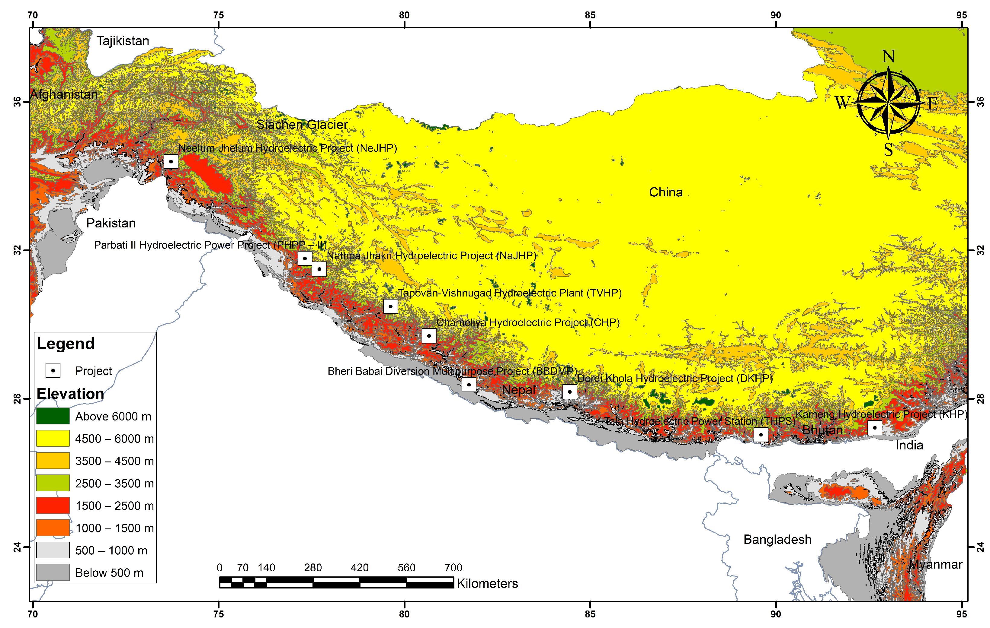
Figure 1 presents the locations of all projects examined in the present study as shown in the elevation map. Roughly from the west to the east, one project studied is located in Pakistan, four in India, three in Nepal and one in Bhutan.
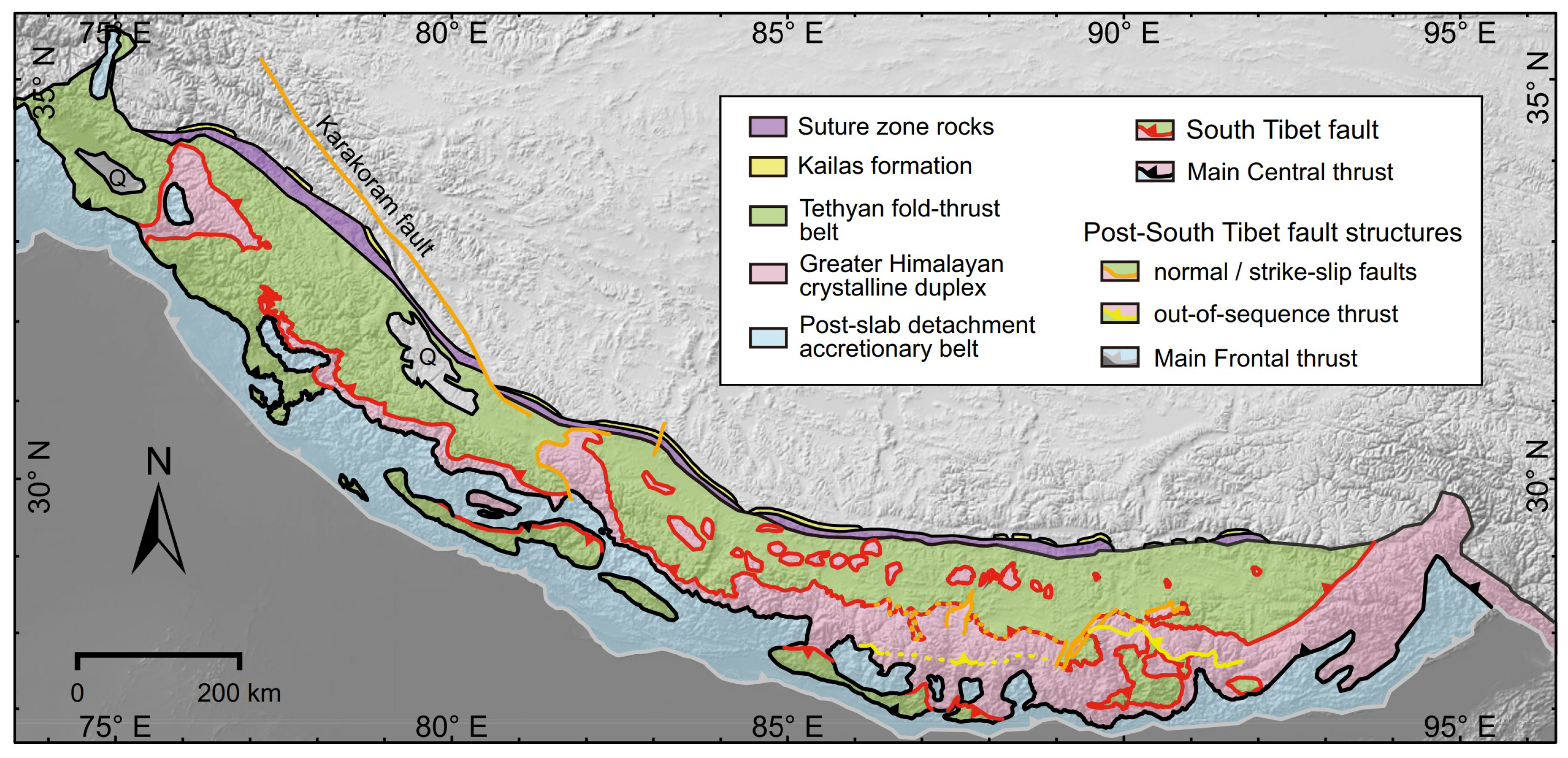
It is of interest to concisely summarize the general geological background of the Himalayas. The Himalayan orogen, a fold-and-thrust belt is a perfect example of continent-continent collision occupying an area of about 600,000
with dimensions of 2400 km ×
km [
23]. The geological map of Himalayas is presented in
Figure 2 which shows the major geological structures. Similar to all other mountains which originate from subduction or collision, the Himalayas with its associated ranges is unique in that it lies on subduction portion of the Indian Plate [
24,
25]. The entire Himalayas can be divided into four WNW–ESE trending tectonostratigraphic units: the Sub Himalayas, the Lesser Himalayas, the Higher Himalayas and the Tibetan-Tethys Himalayas, which are separated by four large-scale, flatly north-dipping thrusts, namely Main Frontal Thrust (MFT), Main Boundary Thrust (MBT), Main Central Trust (MCT) and South Tibetan Detachment System (STDS) from south to north, respectively [
26]. The Indus-Tsangpo Suture Zone overlies the northernmost unit, the Tethys Himalayas above STDS while Holocene basin sediment underlies the Sub Himalayas beneath MFT [
23,
27]. The rock formations in Sub Himalayas comprise sedimentary rocks; conglomerates, sandstones, siltstones, shale and mudstones. The Lesser Himalayas consist of sedimentary to low grade metasedimentary rocks, limestone, dolomites, shale, quartzites, phyllites, schists and marble. The Higher Himalayas are predominantly made up of high-grade metamorphic rocks, while Tethys Himalayas terrigenous and carbonate sedimentary rocks. The structural setting of the Himalayan orogeny is quite complicated; it has undergone different phases of the local and regional scale deformation.
Because of their remarkable height, the Himalayas obstruct the passage of southwesterly rain-bearing winds causing heavy precipitation in the southern slopes, while the northern part, i.e., the Tibetan plateau is largely arid. The precipitation occurs in the form of rain or snow [
29,
30,
31,
32]. The annual average precipitation in the eastern part of these Himalayas is around 3000 mm and the western part is around 1500 mm [
33].
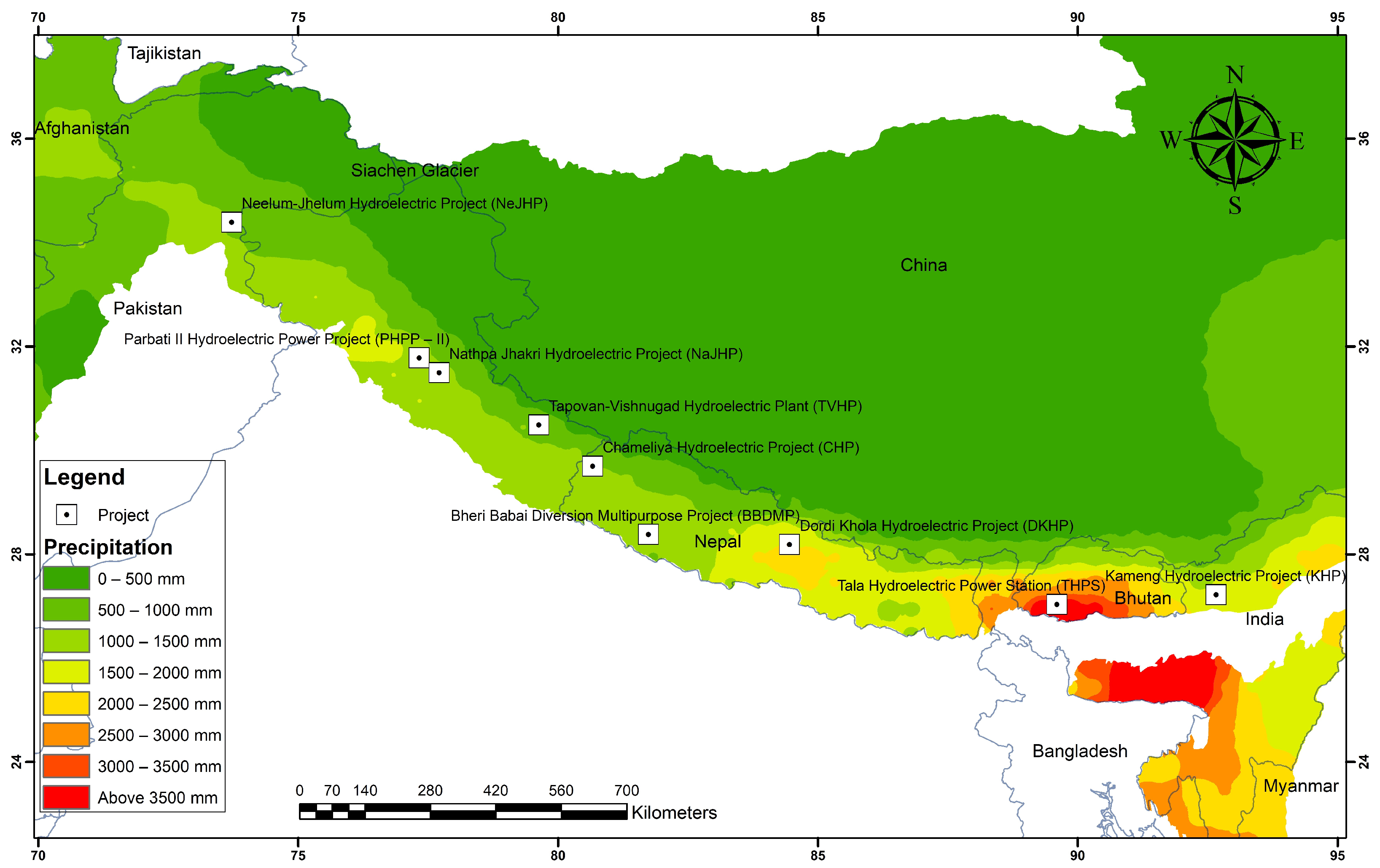
The precipitation map of the Himalayas, prepared based on the average annual precipitation data from 2011 to 2020 provided by the University of East Anglia [
34], is presented in
Figure 3 where the locations of all studied projects are also marked. The precipitation occurs in the form of rain in lower elevations and the snow fall occurs in the higher elevations. The high elevations of these mountains system have permafrost areas which continuously recharge the ground with water throughout the year.
Due to high rainfall and continuous supply of water, there is a tremendous amount of ground water which constantly supplies discharge to the well-developed river systems in the area. The gradient of the rivers and streams is typically very steep because of elevated topography. The continuous flow of water for years have carved deep gorges and river valleys. The rivers flowing in the steep slope with continuous supply of water throughout the year have tremendous potential of power generation. Consequently, it is often necessary to construct tunnels through steep topography and elevated mountains, in order to convey the water for power generation.
3. A Review of Three Prominent Projects in Nepal
Three prominent hydropower projects in Nepal are reviewed in detail in this section. The issues encountered in these projects are very typical of tunnel projects around the Himalayas in this country. Hence, the detailed geological setting of each project location is very important for understanding the potential origin of engineering problems in this region; it is therefore examined in detail and then followed by the discussion on main issues in each project. It is noted that although all projects examined in the present study are construction of hydroelectric power stations, each project is refereed to in the following text according to its official project title documented by the government or authoritative agency, for the sake of consistency and clarity.
3.1. Dordi Khola Hydroelectric Project (DKHP)
3.1.1. Geological Setting
Dordi Khola Hydroelectric project (hereafter referred to as DKHP) is located within in Lamjung district in the Lesser Himalayan Zone of Western Nepal. Geologically, it lies within a tectonically deformed zone containing two major thrust sheets; there is an intra-formational thrust within the project area, and another regional thrust separating rocks of the project area and the rocks of the Himal Group on the northern part of project area. In addition, an axis of large anticlinorium, i.e., Gorkha-Kunchha Anticlinorium, which contains multiple syncline and anticline folds and faults, passes from the southern part of the project area, rending it extremely deformed and metamorphosed.
The project area mainly consists of rocks of the Ranimatta Formation, the Naudanda Formation and the Ghanapokhara Formation. Ranimatta Formation is primarily composed of grey, greenish grey gritty phyllites, gritstones with conglomerates and white massive quartzites in the upper part where basic intrusions are abundant. The Naudanda Formation consists mainly of white, massive, fine to medium grained quartzite with ripple marks interbedded with green phyllites. The Ghanapokhara Formation is composed of black to grey carbonaceous slates and green shales that are mainly made up of white to grey, compact dolomite and dolomitic limestones interbedded. The rocks on the northern part of the project area belong to pre-Cambrian Himal Group rocks while the southern part of the project area is dominated by rocks of the Naudanda Formation [
35].
3.1.2. Challenges Encountered and Potential Solutions
DKHP is a runoff river hydroelectric project. The design discharge and the gross head of the project are 15.28
and 212 m, respectively; the plant is designed to generate a power of 27 MW. The project involves a 2780 m long head race tunnel to convey the water. A representative tunnel section is shown in
Figure 4. The excavated diameter of the tunnel is 3.8 m and the finished diameter is 3.3 m. The tunnel was excavated from two sides, i.e., from both inlet and outlet portion; drill and blasting techniques were used, but in poor geological condition where the tunnel passed through the colluvium deposits, manual excavation was carried out.
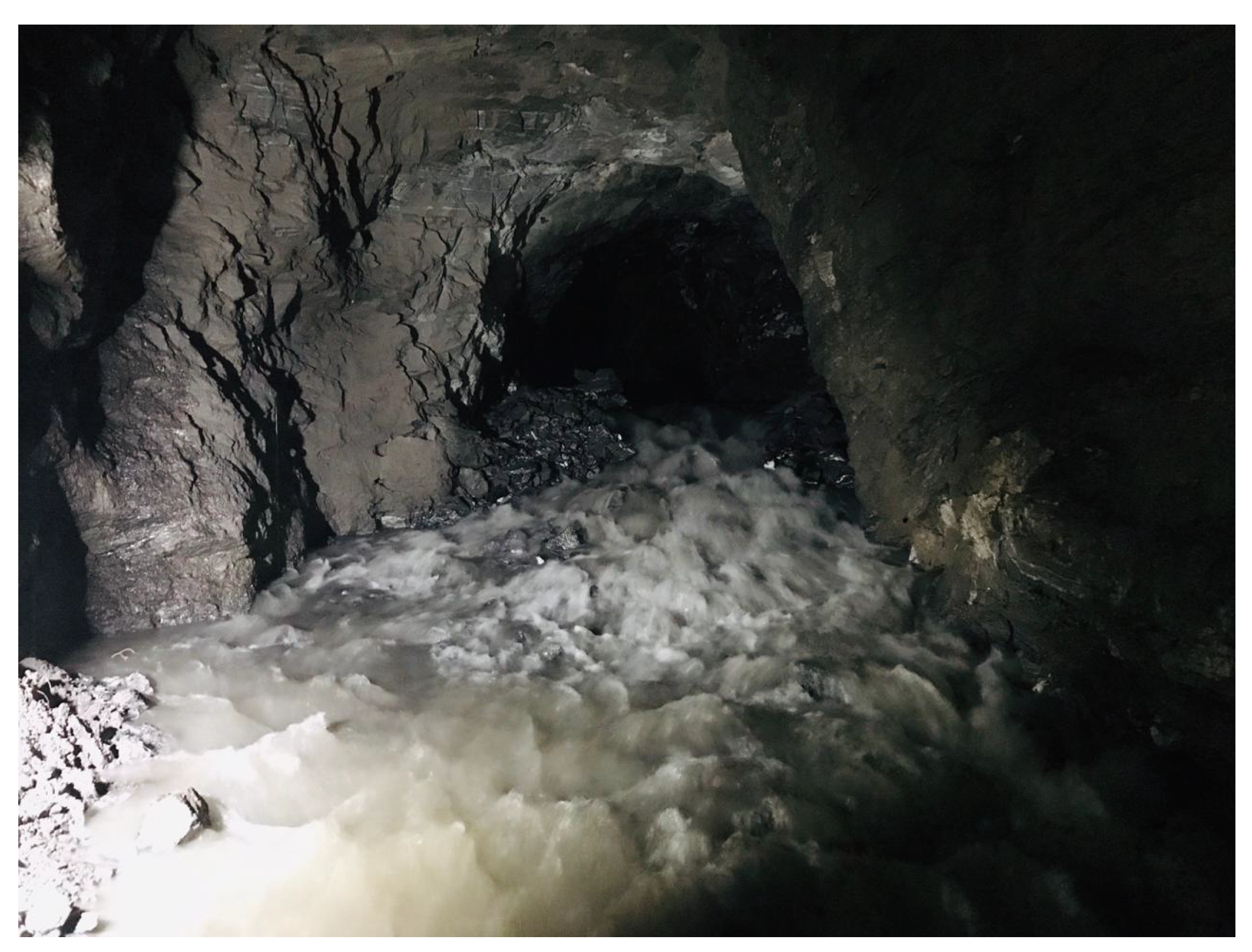
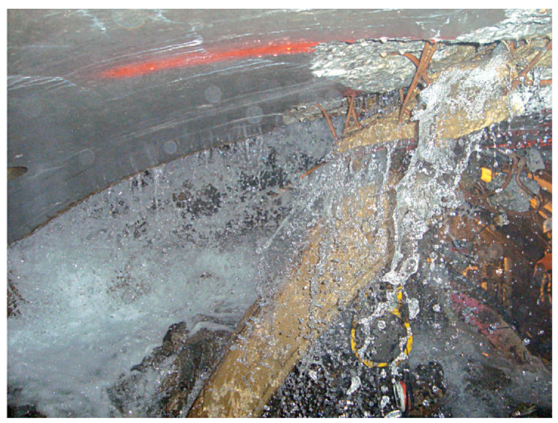
Throughout the section, massive ground water problems were constantly encountered. In most parts of the tunnel, the support was ISMB-150 with 2 mm thick Mild Steel (MS) plate and 20 cm thick M20 concrete lining; ISBM refers to the Indian Standard Medium-weight Beam and is a popular type of steel beam profile in South Asia. However, in some parts of the tunnel alignment, the geologic condition was extremely poor with the colluvium deposits. Heavily jointed phyllite, quartzite and shearing bands were observed at multiple locations along with excessive ingress of ground water.
Figure 5 shows a photo of heavy ingress of water encountered. The discharge of ingressed water could reach as high as 0.3
.
Difficulties with the excavation could be largely attributed to the discrepancy between the estimated geology during the planning stage and actual geologic condition encountered during the construction. The detail design report was prepared anticipating a sound geology; however, the geologic condition turned out extremely poor, for which the excavation team was not fully prepared. Consequently, the excavation team had to explore various state-of-art advanced techniques in the excavation. The condition slowly worsened from the first 330 m of tunneling; the work became extremely difficult due to soft ground which was formed from crushed phyllite and mixed colluvium with excessive ground water. The ground was initially anticipated to be moderately strong phyllite; however, due to weathered rocks along with ground water, the tunnel eventually started to collapse. Both the face and the top part of the tunnel collapsed; the face collapse was stabilized by inserting 26 face dowel bars of 20 mm in diameter separated by 150 mm, and spreading M25 shotcrete as a shield. The horizontal struts were installed to stop the further flow of the muck. To control the crown settlement temporary struts of ISMB-150 were installed to support the ribs (
Figure 6).
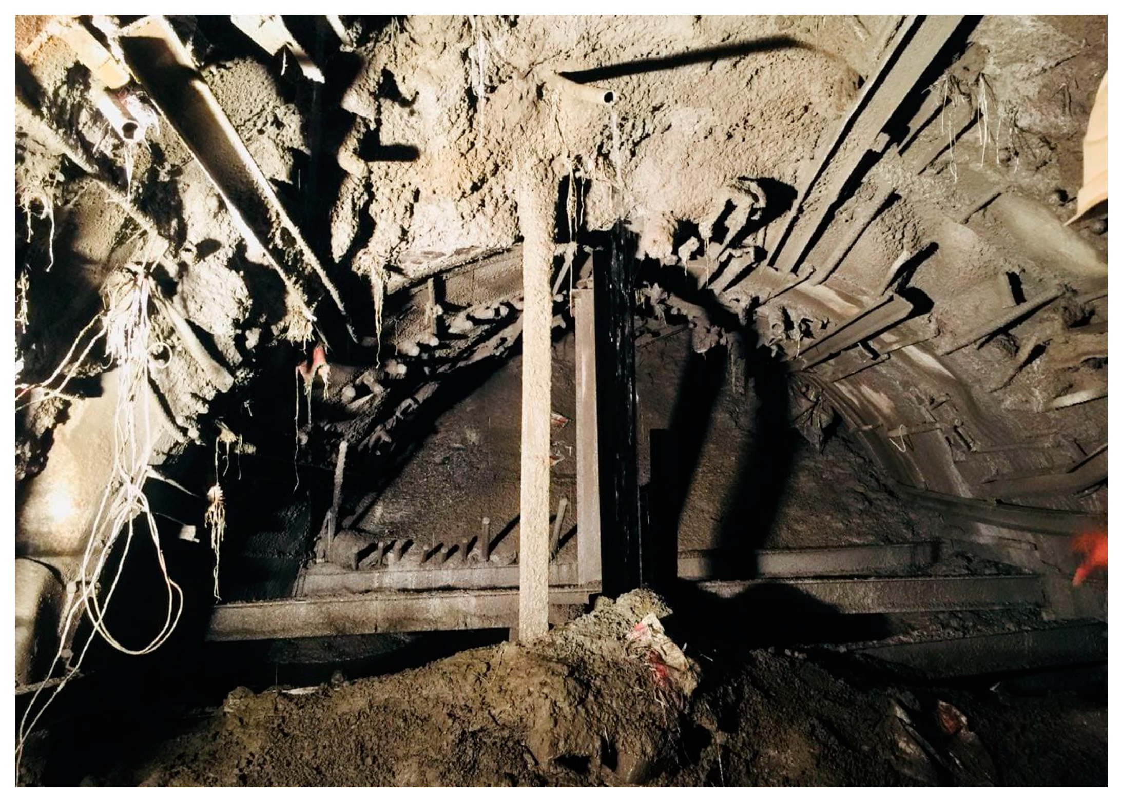
The ground at the invert level was so soft that one of the supporting ISMB-150 beams completely submerged into the ground and was never found again. A steel rib sank halfway and was later removed by cutting its half; this partially sank steel rib is shown in
Figure 7. The project had to invest a large amount of resource at that section, as the work stopped for six months and it took two more years to complete the remaining part of the tunneling work.
From the chainage 1397 m to 1445 m, the rocks turned from phyllite to quartzite. In that section ISMB-150 struts each separated 50 cm apart, were installed as temporary support. However, the geological condition was so poor that eventually they could not be removed to be replaced by permanent support; hence, additional support of ISMB-200 at the spacing of 50 cm was added without removing the temporary support. Subsequently doubly reinforced 250 mm thick M30 grade concrete was cast at the invert with a reinforcement diameter of 16 mm.
It is worth noting that some useful strategies were adopted with good success during the excavation from the chainage of 996 m to 1006 m. This section had crushed quartzite rock fragments with excessive ingress of water. The excavated diameter of 3.8 m was unexpectedly squeezed to 2.8 m, even though the overburden at the chainage was only 90 m. The squeezing was mitigated using ISMB-150 strut at the spacing of 50 cm and M30 grade concrete. The ingress of water was controlled by chemical grouting.
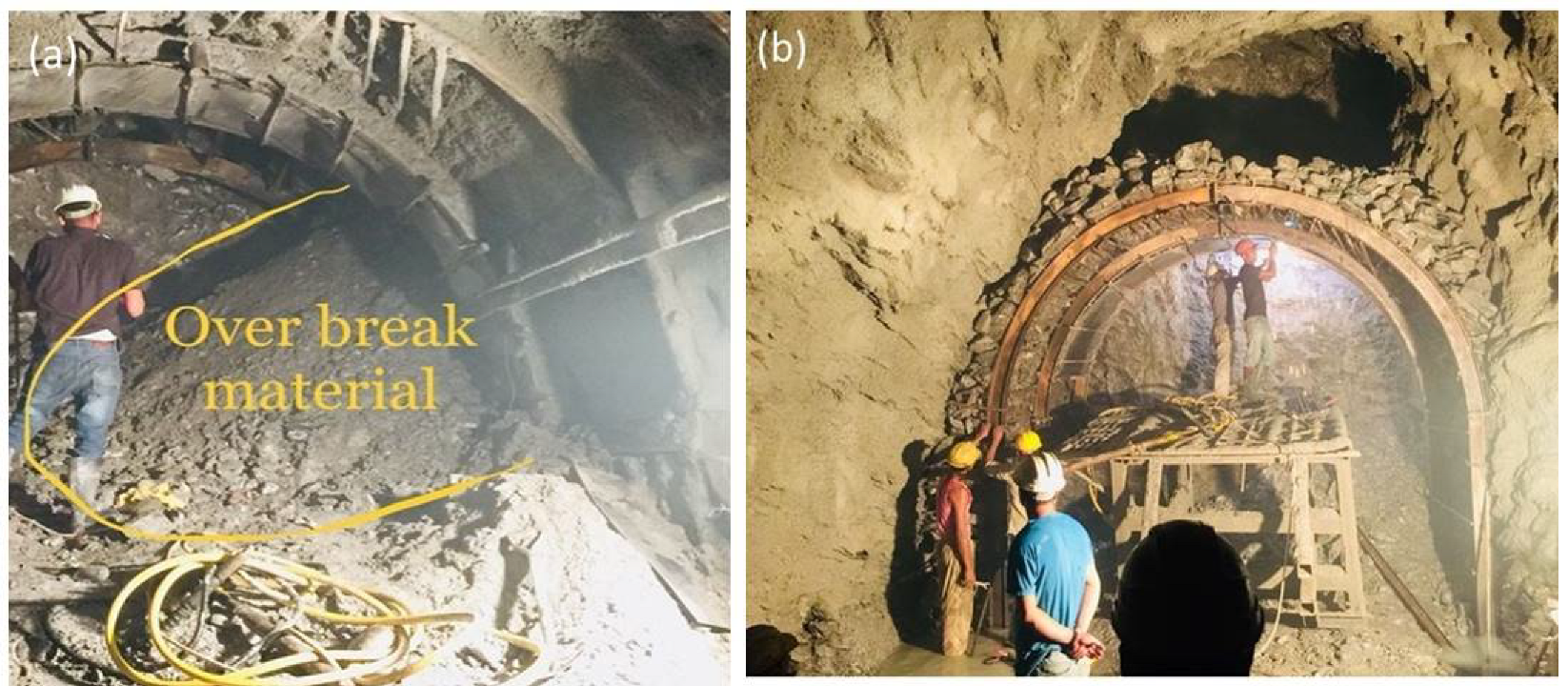
Overbreak was also very common during this project. The overbreak was treated by backfilling with rocks and installing the support of ISMB-150, wire mesh and a mild steel plate, before the fill was finally grouted.
Figure 8a shows a pile of loose debris generated from overbreak, and
Figure 8b shows the filling of overbreak.
3.2. Bheri Babai Diversion Multipurpose Project (BBDMP)
3.2.1. Geological Setting
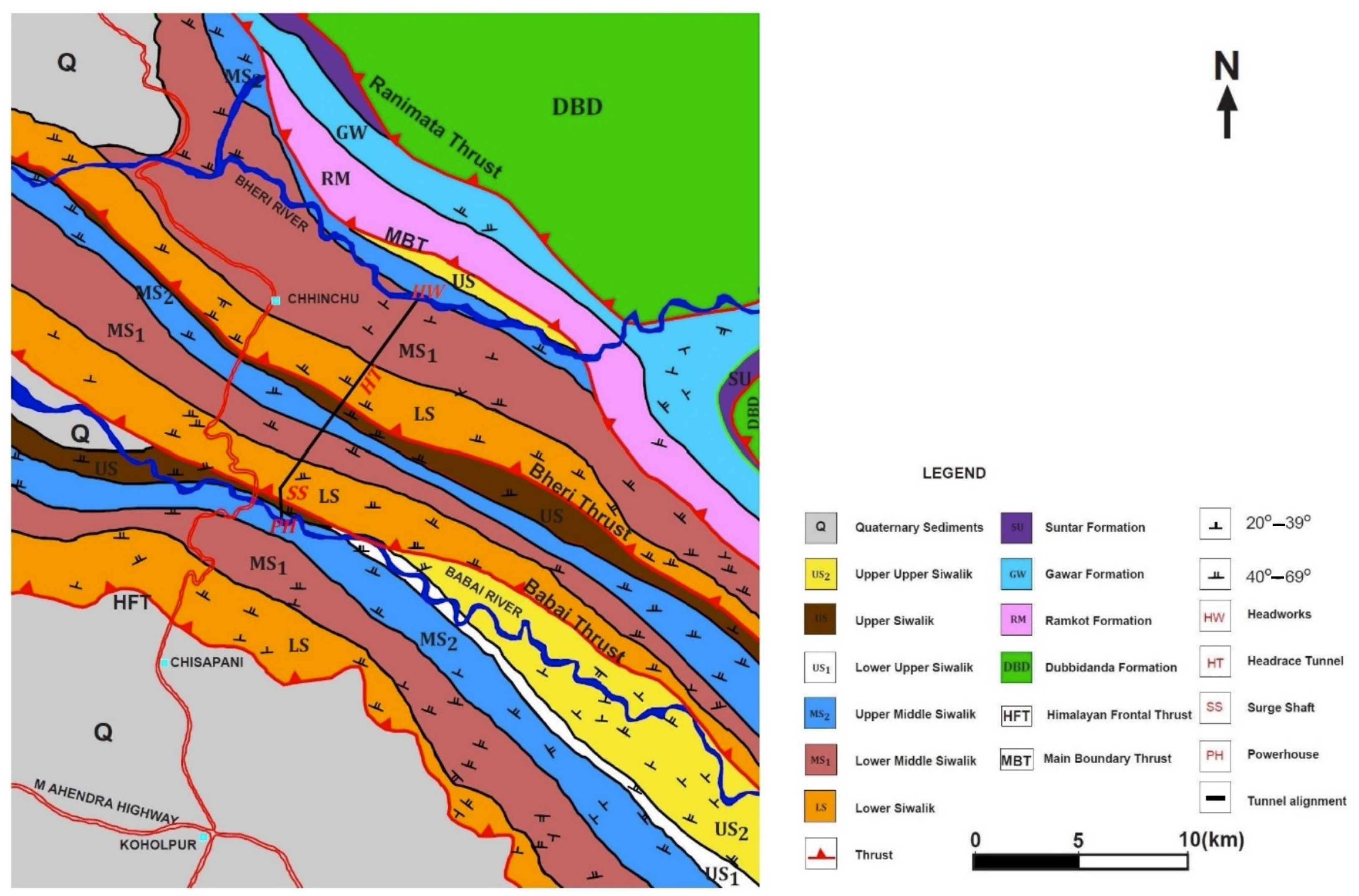
Bheri Babai Diversion Multipurpose Project (BBDMP) is located in Siwaliks which is bounded by the Main Frontal Thrust (MFT) on the south and the Main Boundary Thrust (MBT) on the north. The Neogene aged rocks of the fluvial origin in this zone are classified as lower Siwalik unit, middle Siwalik unit and upper Siwalik unit [
36].
Figure 9 shows the geological map of the project area. Within these units two major thrusts, namely the Babai Thrust and the Bheri Thrust are present in the southern part and the middle part of the head race tunnel of the project. The lower Siwalik unit is repeated twice in the project area due to thrusting. It consists of alternating beds of calcareous mudstone and shale with sandstone intercalations which are representative of lowest stratigraphic unit [
35]. The massive lower Siwalik unit is about 700 m thick [
19]. The lower Siwalik unit is followed by middle Siwalik unit which consists of micaceous sandstone and green grey mudstone with the intercalation of pseudo conglomerate. The middle Siwalik unit is approximately 600 m thick. The upper Siwalik unit begins with 350 m thick mudstone unit followed by well-cemented conglomerates and mudstones [
37].
3.2.2. Challenges Encountered and Potential Solutions
BBDMP is a multipurpose project which uses the water of Bheri river to generate 46 MW electricity; the same water is then used for irrigation of about 51,000 hectares of land in Banke and Bardiya districts. The design discharge of the project is 40 . The length of its head race tunnel to divert the water is 12,210 m, which passes through a fault zone and two tectonic thrust zones as mentioned above. The headrace tunnel passes through the sandstone, mudstone and conglomerates. The tunnel was excavated using the Tunnel Boring Machine (TBM); it was the first tunnel excavated by TBM in Nepal. The excavated diameter of the tunnel is 5.06 m, and the finished diameter is 4.2 m. The maximum overburden along the tunnel length is 823 m. The overall geology of the project was better than initially anticipated; hence, the tunneling work was completed seven months ahead of the original schedule. The average tunneling work rate was 712.4 m/month while the maximum tunneling work rate was 1200 m/month.
Two heavy water inflows entered the tunnel on two occasions, i.e., on 27 October 2017 and on 6 January 2018. The discharge of water ingressed was about 2 in both events. The water was relatively clear and did not create any serious stability problems.
On 16 October 2018, the TBM was trapped at the chainage of 8589 m. The main cause is the variation of the rock strength in the drive direction. The rocks on the left half of the drive direction were hard sandstone, while the rocks on the right were soft mudstone, which caused the tunnel to squeeze and eventually trap the TBM. The overburden depth in this area was less than 140 m and thus the overburden stress was not very high, therefore it is likely that the tectonic stress played a part in the large deformation [
19]. To free the TBM and proceed ahead, initially the thrust was increased up to 18,500 kN but this effort turned out just futile [
38]. Eventually a 0.7 m wide and 6.5 m long bypass was excavated manually from the left side to release the jammed shield.
On 24 October 2018, the cutter head of the TBM was jammed due to collapse of the rock mass with heavy ingress of water. The injection of 1287 kg of polyurethane using a 16 m probe helped to control water flow in the section; the excavation finally resumed after the water ingress was dissipated and the TBM was freed.
3.3. Chameliya Hydroelectric Project (CHP)
3.3.1. Geological Setting
Chameliya Hydroelectric Project (CHP) is located in Darchula district in the lesser Himalayan zone of Sudhurpaschim Province, Nepal. Geologically, it lies within the tectonically deformed zone. There is an active thrust passing very closely from the southern part of the project area. There is an axis of large syncline fold on the south and an axis of major anticline fold just on the north of the project area. The upper pre-Cambrian to late Paleozoic sedimentary to meta-sedimentary rocks of the Midland Group are present within the project area; in particular, the predominant type is the rocks of the Galyang Formation of Midland Group which contains dark grey slates finely intercalated with thin, grey calcareous slates and sandstones. Dark grey to bluish grey fine-grained limestones and dolomitic limestones of various sizes are present within the slate [
35].
Two faults are present at the head race tunnel alignment; the first is at about 900 m and the second at about 2750 m away from the desanding basin. The geological profile (
Figure 10) along the tunnel shows light grey to pink dolomite with some clay band from 0 to 850 m. From 850 m onwards till 1600 m, calcareous slate is interbedded with dolomite. Some quartz veins are present within this chainage. Thin to thickly bedded dolomite is interbedded with calcareous slate with some quartz veins from 1600 m to 2350 m. Heavily jointed dolomite with intercalation of phyllite and talc is found from 2350 m to 3100 m. Thinly bedded highly jointed dolomite is interbedded with talc and talcosic phyllite from 3100 m to 3950 m. From 3950 m onwards, thinly bedded jointed dolomite is interbedded with phyllite and black shale.
3.3.2. Challenges Encountered and Potential Solutions
CHP is a peaking run-of-river plant having 30 MW capacity with an average annual energy generation of 184.21 GWh. It drains 36 of water through the 4067 m long horseshoe shaped pressure tunnel. The excavated diameter of the tunnel is 5.2 m and the finished diameter is 4.2 m. The tunnel excavation was started in 2008 and took about 8 years to complete, although it was originally scheduled to be completed in 2011. The delay was primarily caused by poor geological features and unexpected ground conditions that deviated significantly from the original estimation.
Three audits at the tunnel chainage 700 m, 2800 m and 4000 m were excavated to facilitate timely construction of the tunnel. The major portion of the tunnel was excavated by drilling and blasting method, but in poor geological conditions sequential excavation and manual excavations methods were used. The head race tunnel had severe squeezing problems from the chainage 3100 m to 3940 m. The excavated diameter of the tunnel was significantly reduced due to floor uplift and wall convergence. In some extreme conditions, the lattice girders and the shotcrete even cracked, and the tunnel eventually converged up to 2 m [
20,
39]. The causes of the extreme squeezing are the poor geology and the high overburden, as heavily jointed dolomite interbedded with phyllite (
Figure 10) was observed to experience ductile deformation.
To overcome the squeezing, 150 mm × 150 mm steel ribs with yielding joints were installed, subsequently 200 mm thick shotcrete was sprayed over to keep the yielding joint open so that it could deform along with the deformation of tunnel. A circumferential bar was installed at closure of the yielding joint. After the installation of some ribs and closure of the rib, shotcrete was sprayed over the yielding joint which was left open previously. Eventually 400 mm thick shotcrete layer was sprayed and the squeezing was under control.
4. Several Projects in Bhutan, India and Pakistan
It is of great interest to additionally review several projects in the neighboring countries of Nepal around the Himalayas. These tunnel projects share some common threads with the three projects examined so far, but meanwhile may also exhibit some distinct characteristics affected by their unique geological settings. In this section, the geological setting of each project is concisely summarized along with problems or challenges encountered during the tunneling.
4.1. Tala Hydroelectric Power Station (THPS)
Tala Hydroelectric Power Station (THPS) is located in Tala and Chukha districts near Wangchu river in Bhutan. Geologically the project area lies within the paleo-Proterozoic rocks of the Shumar Formation of Daling-Shumar Group in the Lesser Himalayan rock sequence. This formation is comprised of light grey to white, tan-weathering, very fine-grained, medium to thick-bedded, cliff-forming quartzite, which is typically characterized by interbeds of thin to thick bedded green muscovite-biotite schist and phyllite with diagnostic sigmoidal quartz vein boudins. A thrust passes just from the south of the project area [
40]. The tunnel was excavated by drill and blast technique except in exceptionally poor rock mass where manual removal had to be used. The head race tunnel has a 6.8 m diameter and is 23 km long. The project also included an underground powerhouse of 206 m × 20 m × 44.5 m. Along the tunnel alignment exist high to medium grade metamorphic rocks of Thimphu Formation of Pre-Cambrian age. In this moderately poor geologic condition, highly shattered, moderately to heavily weathered, amphibolite, biotite schist and foliated interbands of quartzite, with up to half meter thick foliation shears are present [
16,
41]. The rock mass was highly water charged. In some area of extremely poor geology, water gushing was often encountered along with the intersection of foliation shears with a thick cross shear; its rock mass classification index
value as developed by Barton et al. [
42], is between 0.05 to 0.14. This indicates that the rock is highly crushed and thus relatively weak and vulnerable to water related problems.
The condition from the chainage 699 m to 709 m of the adit located at Kalikhola stream was extremely adverse; the tunnel even collapsed more than once, i.e., after grouting, consolidation and even after steel ribs and drainage pipe installation. The consolidation of the tunnel face was conducted by using bamboo piling and installing forepole umbrella [
16].
Figure 11a shows the bamboo piling at the tunnel face; this technique turned out very effective against face collapse. Eventually in order to avoid such adverse geological conditions, it was decided that the tunnel should be diverted from the original alignment; however, similar poor rock mass was encountered in the modified alignment as well. In the diverted alignment the excavation was carried out at 2 m pull accompanied with installing the ribs at 0.5 m spacing; but five ribs collapsed due to the high deadload from sheared rock mass (
Figure 11b). Hence, thirteen anchors of 8 m long and 51 mm in diameter were installed at an angle of
in upward direction where the grout was injected. Subsequently twenty-seven perforated pipes of 8 m long and 50 mm in diameter were installed and followed by grouting. The support system consists of steel ribs at 0.5 m spacing, 5∼6 m long rockbolts with 25 mm in diameter every 2 m, 175 mm steel fibre (temporary) shotcrete and a final concrete lining [
43]. These measures turned out very effective and allowed the project to proceed.
4.2. Kameng Hydroelectric Project (KHP)
Kameng Hydroelectric Project (KHP) is located in Arunachal in India in the Northeastern part of the Lesser Himalayas. The major rocks in the area are weak sedimentary rocks, such as carbonaceous shale and siltstone, quartzitic sandstone, and precambrian metasedimentary rocks which include gneiss, quartzite, quartzitic phyllite, phyllite, carbonaceous schist and slate [
44]. The project area is in a tectonically disturbed zone. According to the geological map published by Bhushan [
45], the project area is in the north but close to the Main Boundary Thrust (MBT); as a result of strong tectonic activities, the area is intersected by several thrusts, faults, folds and shears zones. The rock mass is highly fractured, crushed, pulverized, sheared, banded, foliated and jointed; gouge material was observed during tunneling in the sheared zones [
12].
The head race tunnel is modified horseshoe shaped with a diameter of 6.7 m and a length of 14.45 km. The tunnel was excavated by drilling and blasting method. The major problems encountered were heavy seepage, mud flows, debris flows, falling rocks, overbreak and squeezing. One of the major causes for such problems is due to lack of proper geotechnical investigation during the planning stage. The tunnel was originally estimated to pass mainly through fairly strong rocks; however, poor rocks classes were frequently encountered which caused the disturbance in the overall schedule and cost.
High pressure water seepage and blowout occurred in the syncline folds due to development of high pressure in weak areas where the infilling materials was clay at the foliation joints. Mud and debris mixed water flowed out through an opening under high pressure in the vicinity of schist and quartzite which contained a significant amount of kaolin.
Figure 12 shows the images of the mud and debris flow and the high pressure inrush. The flowing of mud, debris, falling of loose rock fragments, overbreaks and chimney formation also led to some cavities. Squeezing was observed in the areas of weak rock mass with high overburden of 800 m to 1000 m as well as in sheared zones. The squeezing of the tunnel continued for months.
To remedy such flow inrush problems, 80∼100 mm perforated forepole pipes of 12 m long were used to grout with microfine cement, ordinary Portland cement and polyurethane at high pressure. In some occasional extreme conditions colloidal silica was also grouted to reduce seepage. For the remedy of cavities, various techniques were employed, including channelizing the seepage by inserting pipes, umbrella roofing or canopy of channel section, pre-supporting, consolidation grouting and forepoling with steel bars [
12]. To control the squeezing, a steel support system was installed and M20 concrete was used to backfill the overbreak. These measures successfully mitigated these encountered problems.
4.3. Tapovan-Vishnugad Hydroelectric Plant (TVHP)
Tapovan-Vishnugad Hydroelectric Project (TVHP) is located in Chamoli district of Uttarakhand in India. The project area belongs to the Higher Himalayan zone composed mainly of medium- to high-grade metamorphic rocks; these rocks are mainly derived from pelitic, semi-pelitic and psammitic sediments, which are sporadically interlayered with metabasics, and to a lesser extent, calcareous rocks [
46]. The Main Central Thrust (MCT) is about 2 km south from the powerhouse area. Due to the presence of MCT the rocks in the region are highly stressed, folded, jointed and sheared. The rocks present in the area are coarse-grained garnet gneisses, garnet-kyanite gneisses, banded gneisses, augen gneisses, foliated gneisses, garnet schists, micaschists and amphibolites [
47]. The head race tunnel is 12.1 km long, of which about 8.6 km was excavated using double shield TBM and the remaining 3.5 km was excavated by conventional methods. Historically it was the first case of double shield TBM ever used in India. The excavated diameter of the tunnel is 6.58 m and the finished diameter is 5.64 m.
The tunnel passes through the Tapovan-Helong Formation overlain by rocks of Joshimath Formation that forms a broad syncline [
48]. The syncline fold has water holding tendency which can cause water-related problems during tunneling. Steep faults and fractures, cut across the main foliation joint allowed the development of high pressure water bearing zone. On 24 December 2009, there was a rock failure when the TBM was operating under the overburden of around 900 m. The failure occurred in jointed rock mass with two prominent joint sets triggered by high water pressure. The failed rock mass then hit the TBM shield and the TBM was trapped and stopped working. Blocky, heavily jointed quartz mica gneiss and a chimney formation were observed above the cutter head [
49]. There was a clear water inrush of about
(
Figure 13), which dramatically increased to 0.7
the next day and the water also turned to turbid. The high water pressure developed also broke the lining at the crown segment. The primary cause of such heavy water ingress might be due to the water inflow from the syncline fold through the fault or failure zone, and the loosening and removal of infilling materials in the joints might also play a part. The TBM was later recovered by excavating a bypass tunnel which also allowed the removal of the inflow water out of the main tunnel. The overall delay due to this incident was 10 months.
Several remedial measures were taken to overcome the collapse and water inrush. The collapsed zone was backfilled. The water inrush was channelized by inserting flexible pipes. Steel arches were installed to support the pre-cast lining. Swellex type rock bolts of 4 m in length and 25 mm in diameter and steel fiber reinforced shotcreting were installed in the cavity zone. Consolidation grouting was applied in the crown of the tunnel between the collapsed area and starting point of the bypass tunnel. These measures were eventually successful in stabilizing the collapsed zone and solving water problems.
4.4. Parbati II Hydroelectric Power Project (PHPP-II)
Parbati II Hydroelectric Project (PHPP-II) is the second stage of a hydropower project being developed in Kullu district of Himachal province, India. Geologically the project area lies within the Kulu window representing the Lesser Himalayan crystalline rock sequence. The Kulu window is bounded by one of the major thrusts of the Himalayan orogeny, i.e., the Main Central Thrust (MCT) [
50]. The project area contains primarily crystalline to meta-sedimentary rock sequence, i.e., schistose granitic gneiss, bioitite-quartzitic schist, quartzite, slate, phyllite and dolomite [
51]. The project area is surrounded by the rocks of the Greater Himalayan Crystalline Complex (GHC) and late Proterozoic rock of the Tethyan Himalayan Sequence. As the project area is close to the Main Central Thrust (MCT), the rocks in the area are highly folded, faulted, jointed, foliated, crushed and sheared. The head race tunnel crosses the upper section of the Lesser Himalayas which mostly consists of granites or gneissic granites followed by quartzites [
10].
The length of the headrace tunnel is 31.37 km and it was drilled with both TBM and conventional methods. The excavated diameter of tunnel is 6.8 m and the finished diameter is 6 m. The overburden along the tunnel alignment varies from 100 m to 1300 m. Around the Mid-October of 2006 when the TBM was operating under the overburden of 1100 m, a rock burst occurred with severe loss in rock mass. On 18 November 2006, there was a sudden discharge of water-silt mixture under high pressure from the probe hole, which later continued to flow from other holes with extreme discharge up to 7
. The flow of silt mixed water continued for more than a week and buried the TBM (
Figure 14). This accident delayed the work for 2 months.
As a remedial measure of rockbursting and overbreak, steel ribs assembled at 0.4 m spacing, fore poling, rock bolts, lagging sheets and concrete backfilling, as well as immediate shotcreting behind the cutter head were applied. Consolidation grouting was carried out using ordinary Portland cement to improve the ground condition ahead of the TBM pass in the weak zones.
4.5. Nathpa Jhakri Hydroelectric Project (NaJHP)
The Nathpa Jhakri Hydroelectric Project (NaJHP) is a run-of-the-river plant constructed by diverting the Satluj river water in Himachal province between (
E,
N) and (
E,
N) in the Higher Himalayas. Geologically the project area lies within the Wangtu Jeori Gneissic Complex in the eastern margin of the Rampur Window [
53]. The rocks in the area are metamorphic rocks, such as gneisses, schists, gneissose schists and basic intrusive (amphibolites), granite and pegmatites [
54]. The rock of the project area is surrounded by the Pre-Cambrian rocks of the Jutogh series which mainly consist of carbonaceous slates, limestones, quartzites and schist, separated by the Main Central Thrust (MCT) [
55], a prominent and well-known shear zone in the Himalayan region [
54]. In this region, the incompetent ductile rocks (mainly schists) have undergone superimposed folding, trending NW-SE to E-W direction with numerous parasitic folds of varied trends. Furthermore, these folds are intersected by a number of steeply dipping faults and shear zones, making the area extremely problematic [
54].
The rated head of the project is 428 m and generates 1500 MW power with a design discharge of 405
. To convey the water, the head race tunnel of 27.37 km long with 10.15 m in diameter is constructed, making it one of the longest and largest hydropower tunnels in the world. The major rocks along the tunnel alignment are gneiss with amphibolites and quartz mica schist. The amphibolite present in the area is hard and extremely jointed. Some shear seams from 5 cm to 1 m thickness were encountered along the tunnel alignment [
54,
56]. The major problem during tunneling was hot water ingress due to the presence of geothermal zones in the area, as well as the high stress at the major fault in this region, i.e., Daj Khad fault [
57,
58].
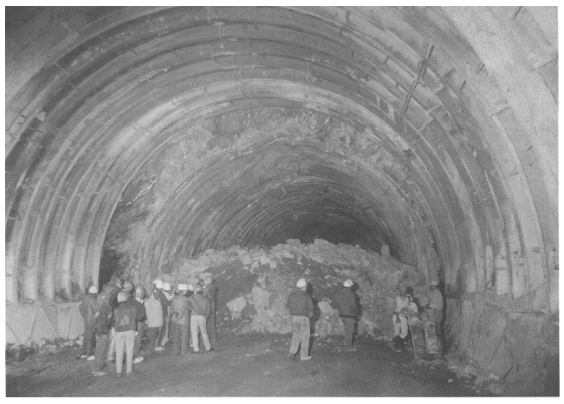
Figure 15 shows a picture of failure of ribs and loose material fallen from the crown and piling up on the ground, resulting from tunnel convergence due to high stress at the shear zone in the tunnel. The I-section support installed in the tunnel deformed almost one meter, which is generally considered unacceptable; eventually the problem was solved by forepoling technique [
57] in which several 12 m long pipes of 10 cm in diameter were drilled over the face and the grout was then injected through those pipes. The excavation was able to proceed after the loose mass became intact.
4.6. Neelum-Jhelum Hydroelectric Project (NeJHP)
The Neelum-Jhelum Hydroelectric Project (NeJHP) is located in the Sub Himalayas of Kasmir in Northeast Pakistan. This region has very adverse geological condition. The major rock types in the area are molassic sedimentary rocks of Murree Formation of Eocene to Miocene age, characterized by alternating mudstone, siltstone and sandstone [
15,
59]. In particular, it is composed of clastic, molasse-type sediments, red and green shales, graywackes and subordinate of conglomerates, forming characteristic fining-upward cyclothems. The red and purple color of these deposits is in general the characteristic feature of the Murree Formation [
60]. The project encountered two major faults, i.e., the Murree Fault and the Muzaffarabad Fault, as well as some other secondary faults. The Murree Fault lies in the headworks area of the project; while the Muzaffarabad Fault along with some other secondary faults, fractured and crushed zone, lie right across the head race tunnel [
59]. This region is in active seismic zone; an earthquake measuring 7.6 on the Richter scale on 8 October 2005 killed more than 80,000 people and was one of strongest earthquakes recorded in the region.
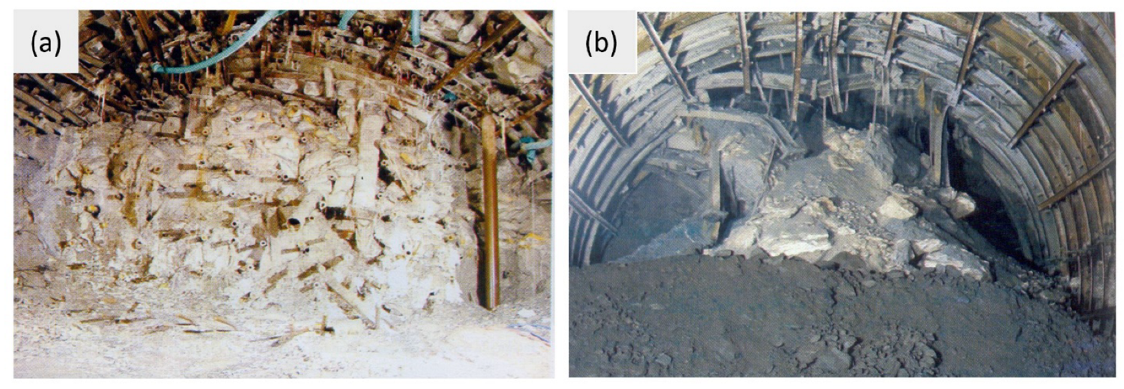
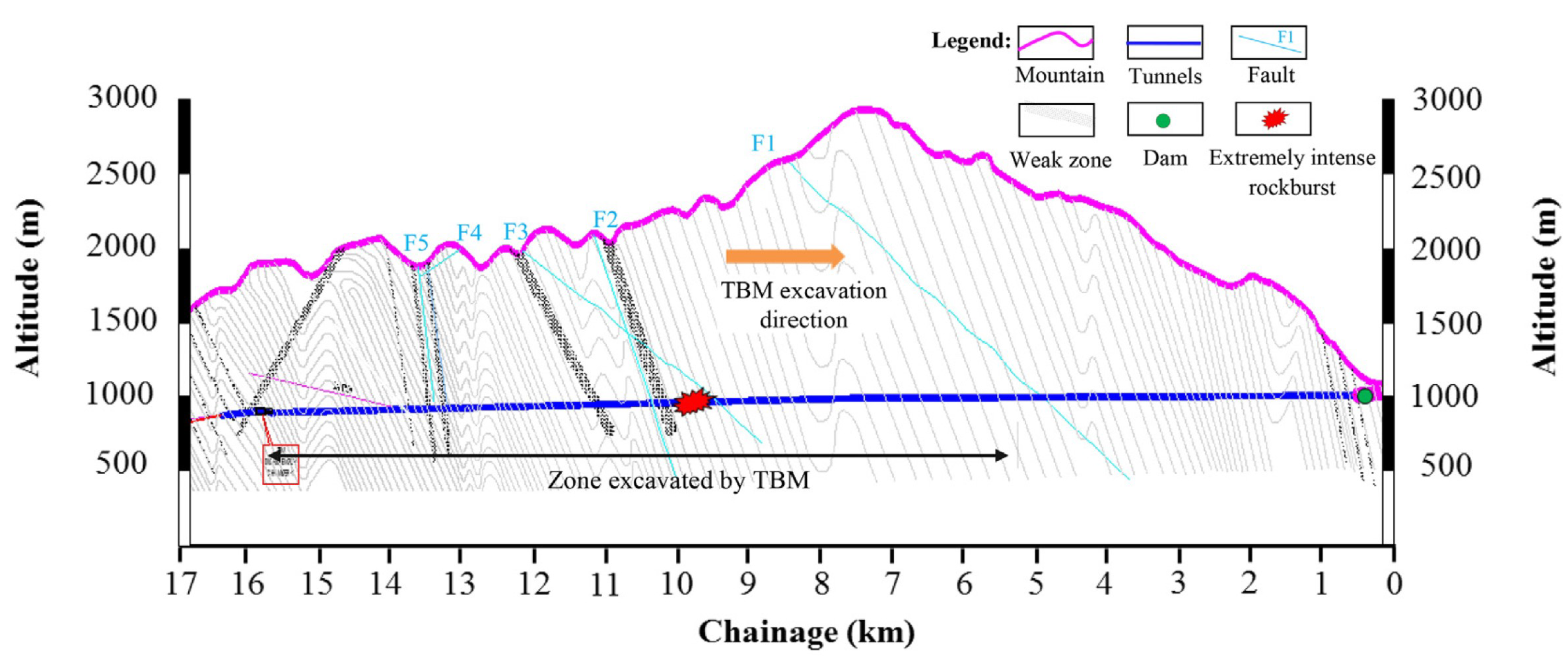
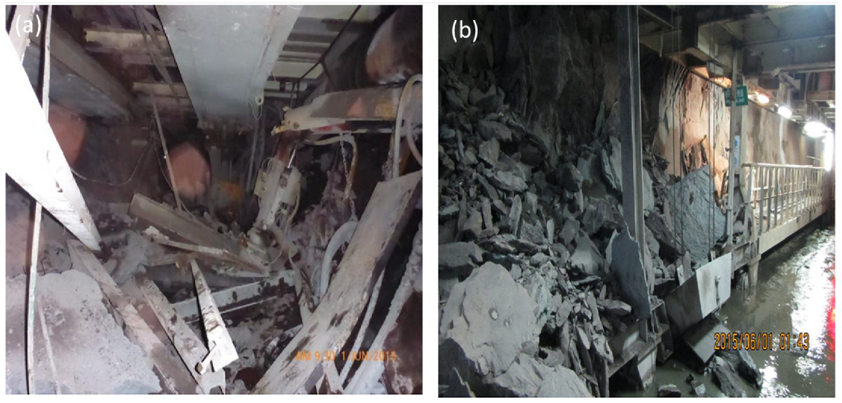
Figure 16 shows general geological setting along the tunnel chainage. The total length of head race tunnel is 28.5 km. It consists of a single tunnel with a length of 8.94 km and a diameter of 11.5 m which was excavated by drilling and blasting technique, and twin tunnels as the remaining part of 19.6 km long, each with an excavated diameter of 8.53 m and excavated with TBM. The maximum overburden above the tunnel is 1870 m. Hundreds of rock bursts occurred in the TBM excavated tunnels. A major strained type rock burst occurred in the high-grade massive sandstone under the overburden of around 1400 m on 31 May 2015 and unfortunately caused three casualties. Large mass of rock from the crown and the wall tumbled down (
Figure 17a), damaging the wire mesh and deforming the steel ribs (
Figure 17b). The TBM used for the excavation was seriously destroyed and the construction was halted for more than half a year.
In situ stress measurement for the project were initially focused on the vulnerable area under maximum overburden and underground powerhouse where the horizontal to vertical stress ratio (
K) was roughly around 1; however, the in situ stress measurements in sandstone bedrock showed that the value of
K could reach up to 2.2 due to the tectonic stress [
61]. The major principal stresses were aligned perpendicular to the tunnel axis, ranging from 73.9 MPa to 141.2 MPa. Under similar geological setting without tectonic effect, the rockburst should have occurred under the maximum overburden, but in this case, rock bursts occurred in the areas other than maximum overburden; hence, it is speculated that these tectonic stresses could be one of the key factors. It can be reasonably concluded that the falling of crown and wall during the above mentioned 2015 event was caused by high vertical stress due to overburden and horizontal tectonic stress.
5. Discussion
Proper site investigation is one of major keys to successful tunneling, in particular, in the complex geological setting around the Himalayas. In this region the subsurface investigation typically involves several techniques such as Electrical Resistivity Tomography (ERT), Seismic Refraction Tomography (SRT), bore hole drilling, test adits, etc. In most of the tunneling work, ERT and SRT techniques are used but the reliability of these methods is currently only about 60 to 80% and they cannot predict the rock mass hundreds of meters below the surface [
62,
63]. Closely spaced very deep borehole drilling in the Himalayas is not feasible economically or technically because the tunnel level is hundreds of meters or even thousands of meters below the surface. Hence, the result obtained might not be representative of overall project site characteristics; this is especially so around the young Himalayas, where active tectonics, high intensity rainfall, geological structures often lead to complicated consequences.
Table 1 summarizes the major issues encountered and characteristics of site condition which are possible causes of the problems. Heavy water ingress is mostly common in all tunnel excavations in the Himalayas. The high-pressure inflow may often occur due to confined water in synclinorium or due to presence of water bodies on the surface which have very high pressure head of hundreds of meters at the tunnel level. Such high-pressure flow can easily erode and wash out the loose materials in between the rock blocks which can consequently cause large destruction; for example, in Parbati II Hydroelectric Power Project (PHPP-II) high pressure water inflow rich in silt content buried the TBM and delayed the work for two months. Similarly, in Tapovan-Vishnugad Hydroelectric Plant (TVHP) the crown collapse in jointed rock mass was triggered by high water pressure and in Kameng Hydroelectric Project (KHP) blowouts and debris flow inside tunnel occurred due to development of high-water pressure in the synclinorium. Therefore, it is suggested that water bodies on the surface and major syncline folds should be carefully surveyed during the planning stage and the tunnel alignment under water bodies or passing through major synclinorium should be avoided.
In all the projects that are reviewed in detail, Dordi Khola Hydroelectric Project (DKHP), Chamelia Hydroelectic Project (CHP) and Kameng Hydroelectric Project (KHP), the geologic condition was far more challenging and complex than anticipated and caused too many problems during the excavation. Meanwhile, in Bheri Babai Diversion Multipurpose Project (BBDMP) the geology turned out better than anticipated which helped to complete the tunneling work ahead of the schedule. In BBDMP early planning and preparation were made to overcome the adverse geologic condition; for example, shield lubrication ports were installed in the TBM through which bentonite could be injected to reduce the friction between the TBM skin and surrounding rock if the TBM gets trapped. Similarly, forepoling ports were also installed with an intent to stabilize the weak rock mass. Although eventually neither shield lubrication ports nor forepoling ports were used since the ground condition was fairly well, had the ground been worse than anticipated, they would have facilitated successful completion of the work safely in due time. In DKHP the engineers had never anticipated squeezing problem at the chainage of 996 m to 1006 m because the overburden was just 90 m; had they planned for the worst case, the work would have been completed on schedule in that section.
Due to active tectonic activities in the Himalayas, the stresses generated by tectonic movement can dominate the overburden stresses resulting from the gravity. However, these tectonic stresses are very difficult to assess and often overlooked during the planning stage; the practicing engineers and geologists tend to measure the in situ stresses only at those locations deemed critical, e.g., at maximum overburden, around distressed areas or towards the valley. It is entirely possible in this region that there are other vulnerable locations with very high stresses due to tectonic activities. In Neelum-Jhelum Hydroelectric Project (NeJHP) the failures (rock burst) occurred at the area other than the critical overburden, even though the rock types and other geological conditions were similar. In addition, because of poor geological conditions such as interbedding of different rock types with different physical and mechanical properties, differential weathering may cause the stability problems; for example in Chameliya Hydroelectric Project (CHP), it was originally anticipated that the most challenging section should have been around between the chainage 1100 m to 1400 m due to weak slate and maximum overburden (
Figure 10), but the squeezing problem was encountered from 3100 m to 3900 m where the dolomite was interbedded with phyllite and was considerably weakened.
It is worth noting that the use of TBM can be of enormous benefit but needs to be carefully planned in this region. TBM can excavate tunnel at a very high work rate and thus save both time and costs. The shielded TBM can also protect workers from rockfall and rockburst, but in some extreme (highly fragile) geological conditions with very high in situ stress (either due to overburden or tectonic activities), the result can be mixed. In case of Bheri Babai Diversion Multipurpose Project (BBDMP) both time and cost were saved and no fatal accidents occurred by the use of double shield TBM as the ground condition was fairly well; however, in Neelum-Jhelum Hydroelectric Project (NeJHP), Tapovan-Vishnugad Hydroelectric Plant (TVHP) and Parbati II Hydroelectric Power Project (PHPP-II), both the time and cost increased. In the case of the other five projects where TBM was not used, with the exception of DKHP whose tunnel diameter was too small for TBM, had there been use of TBM without proper planning in CHP, THP, KHP and NaJHP, the extreme condition would have rendered it counterproductive and the problems would have been even more severe.
6. Conclusions
The present study offers a detailed survey of various critical factors during tunneling in the Himalayas. Three hydropower tunnel projects from Nepal and six others from surrounding countries are examined in an effort to identify the common geological characteristics and engineering challenges encountered in the tunneling around the Himalayas. The main conclusions can be summarized as follows.
Most of the problems during tunneling were associated with poor geology such as shear zones, faults, folds, etc. In shear zones with highly crushed rock mass face, wall and crown collapse were frequently encountered. Under high overburden of around 1000 m or deeper, extremely fatal rock bursts were common. Extreme rock burst in Neelum-Jhelum Hydroelectric Project were observed at the location far lower than the maximum overburden, which could be attributed to the combined effect of gravitational and tectonic stresses.
Tunnel squeezing issues were observed in soft rocks under a wide range of overburden. Overbreak was common in most of the tunnels in heavily jointed areas. Water ingress was common in all the tunnels, although the severity was less in the tunnels located in Sub-Himalayas than those in Lesser Himalayas and Higher Himalayas. The water ingress was also affected by geological setting, for example, in Kameng Hydroelectric Project and in Tapovan-Vishnugad Hydroelectric Plant, the excessive ingress was facilitated by the presence of syncline fold.
In the high Himalayas, it is difficult to predict the rockmass by SRT or ERT methods as the tunnel level is very deep, i.e., hundreds of meters below the surface and occasionally even more than 1000 m. Close drilling to such depths are not feasible technically or economically, therefore probe drilling can be a very effective method for planning the excavation works.
In terms of excavation methods adopted, TBM can reduce the tunnel excavation time and cost significantly with proper planning, if the geological condition is favorable; otherwise the problem can be worsened because of high gravitational and tectonic stresses, which may trap the TBM due to tunnel convergence or destroy the TBM with extreme rock bursts. The excessive water inflow mixed with debris can also adversely affect the TBM operation, if the overlying strata are heavily recharged with water or if there are lakes or streams on the surface above or near the tunnel alignment.
A number of remedial strategies or techniques were useful in the tunneling in the Himalayas. Channeling, drainpipe installation and grouting can be effective to mitigate the excessive water ingress. Squeezing problems may be reduced by supporting ribs with yielding joints. In very poor geology with crushed and sheared rock mass where face, wall or crown collapse, forepoling with grouting can improve the stability; in extremely poor ground condition where the face flows almost such as muck material, stability can be improved by forepoling, grouting and installing the dowel bars on the face along with the horizontal struts which can stop the flow of muck. The detached rockfalls from the crown and walls can be prevented by rockbolting.
While the grade of metamorphism rises from south to north, i.e., from the Sub Himalayas to the Higher Himalayas and therefore it is generally perceived that the strength of rock formations across the Himalayas may also follow such a trend; however, due to several other factors involved in the subsurface such as rock discontinuities, ground water conditions, overburden and tectonic stresses, the distribution of severity of challenges across the projects examined does not support such a trend. Various serious problems emerge in the projects located in the Higher Himalayas and Lesser Himalayas, while Bheri Babai Diversion Multipurpose Project in the Sub Himalayas did not encounter any major issues other than water ingress. Hence, the actual Himalayan geology and underground conditions are very complex with great uncertainties; proper site exploration and careful planning rather than relying on general assumption or empirical knowledge is critical to the successful tunneling in the Himalayas.
Author Contributions
Conceptualization, D.K.; methodology, D.K., K.G., H.D. and L.H.; software, D.K., K.G. and H.D.; formal analysis, D.K. and L.H.; investigation, D.K., K.G., H.D. and S.K.; resources, L.H.; data curation, D.K., K.G. and H.D.; writing—original draft preparation, D.K., S.K. and L.H.; writing—review and editing, D.K. and L.H.; visualization, D.K.; supervision, L.H.; project administration, L.H. All authors have read and agreed to the published version of the manuscript.
Funding
This research received no external funding.
Data Availability Statement
Data used in the present study is contained within the article.
Acknowledgments
All authors would like to thank Deependra Bahadur Shahi for his assistance during the preparation of the manuscript. The first author (D.K.) and fifth author (L.H.) wish to acknowledge the financial support provided by the University of Toledo through a Summer Research Fellowship during the preparation of this manuscript.
Conflicts of Interest
The authors declare no conflict of interest.
References
- Latha, G.M.; Garaga, A. Stability analysis of a rock slope in Himalayas. Geomech. Eng. 2010, 2, 125–140. [Google Scholar] [CrossRef]
- Bhandari, B.P.; Dhakal, S. Lithological control on landslide in the Babai Khola watershed, Siwaliks zone of Nepal. Am. J. Earth Sci. 2018, 5, 54–64. [Google Scholar]
- Panthi, K.K.; Shrestha, P.K. Estimating tunnel strain in the weak and schistose rock mass influenced by stress anisotropy: An evaluation based on three tunnel cases from Nepal. Rock Mech. Rock Eng. 2018, 51, 1823–1838. [Google Scholar] [CrossRef]
- Dangi, H.; Bhattarai, T.N.; Thapa, P.B. An approach of preparing earthquake induced landslide hazard map: A case study of Nuwakot District, central Nepal. J. Nepal Geol. Soc. 2019, 58, 153–162. [Google Scholar] [CrossRef]
- KC, D.; Dangi, H.; Hu, L. Assessing landslide susceptibility in the northern stretch of Arun Tectonic Window, Nepal. CivilEng 2022, 3, 525–540. [Google Scholar] [CrossRef]
- Patric, J.O. Subduction followed by collision: Alpine and Himalayan examples. Phys. Earth Planet. Inter. 2001, 127, 227–291. [Google Scholar]
- Molnar, P. Continental tectonics in the aftermath of plate tectonics. Nature 1988, 335, 131–137. [Google Scholar] [CrossRef]
- Bollinger, L.; Henry, P.; Avouac, J.P. Mountain building in the Nepal Himalaya: Thermal and kinematic model. Earth Planet. Sci. Lett. 2006, 244, 58–71. [Google Scholar] [CrossRef]
- Dipietro, J.A.; Pogue, K.R. Tectonostratigraphic subdivisions of the Himalaya: A view from the west. Tectonics 2004, 23, 1554. [Google Scholar] [CrossRef]
- Goel, R.K. Experiences and lessons from the use of TBM in the Himalaya-A review. Tunn. Undergr. Space Technol. 2016, 57, 277–283. [Google Scholar] [CrossRef]
- Panthi, K.K.; Nilsen, B. Uncertainty analysis of tunnel squeezing for two tunnel cases from Nepal Himalaya. Int. J. Rock Mech. Min. Sci. 2007, 44, 67–76. [Google Scholar] [CrossRef]
- Alam, M.H.; Sharma, M.K. Criticalities encountered in Construction of (HRT) Head Race Tunnel of Kameng Hydro Electric Project (600MW), In Arunachal Pradesh, India. Int. J. Sci. Eng. Res. 2014, 5, 217–231. [Google Scholar]
- Dwivedi, R.D.; Singh, M.; Viladkar, M.N.; Goel, R.K. Prediction of tunnel deformation in squeezing grounds. Eng. Geol. 2013, 161, 55–64. [Google Scholar] [CrossRef]
- Panthi, K.K. Evaluation of rock bursting phenomena in a tunnel in the Himalayas. Bull Eng Geol Environ. 2012, 71, 761–769. [Google Scholar] [CrossRef]
- Naji, A.M.; Emad, M.Z.; Rehman, H.; Yoo, H. Geological and geomechanical heterogeneity in deep hydropower tunnels: A rock burst failure case study. Tunn. Undergr. Space Technol. 2019, 84, 507–521. [Google Scholar] [CrossRef]
- Dev, H.; Singh, R.; Sengupta, C.K. Rock Supports and geological appraisal for head race tunnel of Tala Hydroelectric Project, Bhutan. J. Rock Mech. Tunn. Tech. 2013, 19, 29–46. [Google Scholar]
- Goel, R.K.; Jethwa, J.L.; Paithankar, A.G. Tunnelling through the young Himalayas—A case history of the Maneri-Uttarkashi power tunnel. Eng. Geol. 1995, 39, 31–44. [Google Scholar] [CrossRef]
- Panthi, K.K.; Nilsen, B. Predicted versus actual rock mass conditions: A review of four tunnel projects in Nepal Himalaya. Tunn. Undergr. Space Technol. 2007, 22, 173–184. [Google Scholar] [CrossRef]
- Dhungel, L.R. Geological, Engineering Geological and Geotechnical Study of the Bheri-Babai Diversion Project Surkhet, Mid-Western Nepal. Master’s Thesis, Tribhuvan University, Kathmandu, Nepal, 2012. [Google Scholar]
- Basnet, C.B.; Shrestha, P.K.; Panthi, K.K. Analysis of squeezing phenomenon in the headrace tunnel of Chameliya project, Nepal. Hydro Nepal: J. Water Energy Environ. 2013, 13, 44–51. [Google Scholar]
- Dewey, J.F.; Lamb, S.H. Active tectonics of the Andes. Tectonophysics 1992, 205, 79–95. [Google Scholar] [CrossRef]
- Hoek, E. Big tunnels in bad rock. J. Geotech. Geoenviron. Eng. 2001, 127, 726–740. [Google Scholar] [CrossRef]
- Dhital, M.R. Geology of the Nepal Himalaya; Springer International Publishing: Cham, Switzerland, 2015. [Google Scholar]
- Seeber, L.; Armbruster, J.G.; Quittmeyer, R.C. Seismicity and continental subduction in the Himalayan arc. Zagros Hindu Kush Himalaya Geodyn. Evol. 1981, 3, 215–242. [Google Scholar]
- Mattauer, M. Intracontinental subduction, crust-mantle decollement and crustal-stacking wedge in the Himalayas and other collision belts. Geol. Soc. Lond. 1986, 19, 37–50. [Google Scholar] [CrossRef]
- Gansser, A. Geology of the Himalayas, 1st ed.; Interscience: London, UK, 1964; p. 289. [Google Scholar]
- Henderson, A.L.; Najman, Y.; Parrish, R.; Mark, D.F.; Foster, G.L. Constraints to the timing of India-Eurasia collision; a re-evaluation of evidence from the Indus Basin sedimentary rocks of the Indus-Tsangpo Suture Zone, Ladakh, India. Earth Sci. Rev. 2011, 106, 265–292. [Google Scholar] [CrossRef]
- Webb, A.A.G.; Guo, H.; Clift, P.D.; Husson, L.; Muller, T.; Costantino, D.; Yin, A.; Xu, Z.; Cao, H.; Wang, Q. The Himalaya in 3D: Slab dynamics controlled mountain building and monsoon intensification. Lithosphere 2017, 9, 637–651. [Google Scholar] [CrossRef]
- Bookhagen, B. Appearance of extreme monsoonal rainfall events and their impact on erosion in the Himalaya. Geomat. Nat. Hazards Risk 2010, 1, 37–50. [Google Scholar] [CrossRef]
- Nandargi, S.; Dhar, O.N. Extreme rainfall events over the Himalayas between 1871 and 2007. Hydrol. Sci. J. 2011, 56, 930–945. [Google Scholar] [CrossRef]
- Viste, E.; Sorteberg, A. Snowfall in the Himalayas: An uncertain future from a little-known past. Cryosphere 2015, 9, 1147–1167. [Google Scholar] [CrossRef]
- Parida, B.R.; Behera, S.N.; Bakimchandra, O.; Pandey, A.C.; Singh, N. Evaluation of satellite-derived rainfall estimates for an extreme rainfall event over Uttarakhand, Western Himalayas. Hydrology 2017, 4, 22. [Google Scholar] [CrossRef]
- Britannica. Climate of the Himalayas. Available online: https://www.britannica.com/place/Himalayas/Climate (accessed on 25 June 2022).
- Climate Research Unit (University of East Anglia). High-Resolution Gridded Datasets and Derived Products. Available online: https://crudata.uea.ac.uk/cru/data/hrg (accessed on 28 June 2022).
- DMG. Geological Map of Nepal; Department of Mines and Geology: Kathmandu, Nepal, 1994. [Google Scholar]
- Mugnier, J.L.; Leturmy, P.; Mascle, G.; Huyghe, P.; Chalaron, E.; Vidal, G.; Husson, L.; Delcaillau, B. The Siwaliks of western Nepal: I. Geometry and kinematics. J. Asian Earth Sci. 1999, 17, 629–642. [Google Scholar] [CrossRef]
- Kotlia, B.S.; Goswami, P.K.; Joshi, L.M.; Singh, A.K.; Sharma, A.K. Sedimentary environment and geomorphic development of the uppermost Siwalik molasse in Kumaun Himalayan Foreland Basin, North India. Geol. J. 2018, 53, 159–177. [Google Scholar] [CrossRef]
- Robbins. Bheri Babai Diversion Multipurpose Project. Available online: https://www.robbinstbm.com/projects/bheri-babai/ (accessed on 24 April 2022).
- Basnet, C.B. Evaluation on the Squeezing Phenomenon at the Headrace Tunnel of Chameliya Hydroelectric Project, Nepal. Master’s Thesis, Norwegian University of Science and Technology, Trondheim, Norway, 2013. [Google Scholar]
- Long, S.; McQuarrie, N.; Tobgay, T.; Grujic, D.; Hollister, L. Geologic map of Bhutan. J. Maps 2011, 7, 184–192. [Google Scholar] [CrossRef]
- Sripad, S.K.; Raju, G.D.; Singh, R.; Khazanchi, R.N. Instrumentation of underground excavations at Tala Hydroelectric Project in Bhutan. In Proceedings of the International Workshop on Experiences and Construction of Tala Hydroelectric Project Bhutan, New Delhi, India, 14–15 June 2007; pp. 269–282. [Google Scholar]
- Barton, N.; Lien, R.; Lunde, J. Engineering classification of rock masses for the design of tunnel support. Rock Mech. 1974, 6, 189–236. [Google Scholar] [CrossRef]
- Tripathy, P.K.; Kapadia, H.; Kumar, S. Use of Alkali free Accelerators in Tala Hydroelectric Project. In Proceedings of the Tunnelling Asia, New Delhi, India, 26–29 September 2000; pp. 292–295. [Google Scholar]
- Sarma, K.P.; Bhattacharjee, S.; Nandy, S.; Konwar, P.; Mazumdar, N. Structure, stratigraphy and magnetic susceptibility of bomdila gneiss, Western Arunachal Himalaya, India. J. Geol. Soc. India 2014, 84, 544–554. [Google Scholar] [CrossRef]
- Bhusan, S.K. Reappraisal of the geology between the MBF and the MCT in Western Arunachal Pradesh. In Geological Studies in the Eastern Himalayas; Verma, P.K., Ed.; Pilgrim books Pvt. Ltd.: New Delhi, India, 1999; pp. 161–176. [Google Scholar]
- Heim, A.; Gansser, A. Central Himalaya: Geological observations of the Swiss expedition 1936. Mem. Soc. Helv. Sci. Nat. 1939, 73, 1–245. [Google Scholar]
- Naithani, A.K.; Krishna Murthy, K.S. Geological and geotechnical investigations of Tapovan-Vishnugad Hydroelectric Project, Chamoli District, Uttarakhand, India. J. Nepal Geol. Soc. 2006, 34, 1–16. [Google Scholar] [CrossRef]
- Nawani, P.C. Groundwater ingress in head race tunnel of Tapovan: Vishnugad Hydroelectric Project in Higher Himalaya, India. In Engineering Geology for Society and Territory; Lollino, G., Giordan, D., Thuro, K., Carranza-Torres, C., Wu, F., Marinos, P., Delgado, C., Eds.; Springer International Publishing: Cham, Switzerland, 2015; Volume 6, pp. 941–945. [Google Scholar]
- Brandl, J.; Gupta, V.K.; Millen, B. Tapovan-Vishnugad hydroelectric power project experience with TBM excavation under high rock cover. Geomech. Tunn. 2010, 5, 501–509. [Google Scholar]
- Alexander, A.; Webb, G.; Yin, A.; Harrison, T.M.; Celerier, J.; Burgess, W.P. The leading age of the greater Himalayan crystalline complex reveled in the NW Indian Himalaya: Implications for the evolution of the Himalaya. Geology 2007, 35, 955–958. [Google Scholar]
- Panthi, K.K. Assessment on stress induced instability in a tunnel project of the Himalaya. In Proceedings of the 12th ISRM International Congress on Rock Mechanics, Beijing, China, 18–21 October 2011. [Google Scholar]
- Clark, J.; Chorley, S. The greatest challenges in TBM tunneling: Experiences from the field. In Proceedings of the 2014 North American Tunneling Conference, Los Angeles, CA, USA, 22–25 June 2014; pp. 101–108. [Google Scholar]
- Thakur, V.C. Geology of western Himalaya. Phys. Chem. Earth. 1992, 19, 1–355. [Google Scholar]
- Bhasin, R.; Barton, N.; Grimstad, E.; Chryssanthakis, P. Engineering geological characterization of low strength anisotropic rocks in the Himalayan region for assessment of tunnel support. Eng. Geol. 1995, 40, 169–193. [Google Scholar] [CrossRef]
- Bhargava, O.N. The tectonic windows of the Lesser Himalaya. Himal. Geol. 1980, 10, 134–155. [Google Scholar]
- Kumar, N.; Samadhiya, N.K.; Anbalagan, R. Application of rock mass classification systems for tunneling in Himalaya, India. Int. J. Rock Mech. Min. Sci. 2004, 41, 852–857. [Google Scholar] [CrossRef]
- Hoek, E. Putting numbers to geology-an engineer’s viewpoint. Q. J. Eng. Geol. Hydrogeol. 1999, 32, 1–19. [Google Scholar] [CrossRef]
- Prabhakar, K.; Pankaj, S.; Pathak, R.P.; Sameer, V.; Mahure, N.V.; Ratnam, M. Concrete exposed to hot water springs—It’s designing and monitoring post construction performance-A case study. Int. J. Civ. Struct. Eng. 2013, 4, 125. [Google Scholar]
- Li, P.X.; Feng, X.T.; Feng, G.L.; Xiao, Y.X.; Chen, B.R. Rockburst and microseismic characteristics around lithological interfaces under different excavation directions in deep tunnels. Eng. Geol. 2019, 260, 105209. [Google Scholar] [CrossRef]
- Bossart, P.; Ottiger, R. Rocks of the Murree Formation in northern Pakistan: Indicators of a descending foreland basin of late Paleocene to middle Eocene age. Eclogae Geol. Helv. 1989, 82, 133–165. [Google Scholar]
- Ullah, I.; Peach, G.; Nadeem, M. Tunnel Boring Machine advance ground investigation in rockburst-prone ground conditions on Neelum Jhelum project. In Proceedings of the 1st GeoMEast International Congress and Exhibition, Sharm El-Sheikh, Egypt, 16–20 July 2017; pp. 53–75. [Google Scholar]
- Oldenborger, G.A.; Knoll, M.D.; Routh, P.S.; LaBrecque, D.J. Time-lapse ERT monitoring of an injection/withdrawal experiment in a shallow unconfined aquifer. Geophysics 2007, 72, F177–F187. [Google Scholar] [CrossRef]
- Row, B.S.; Knutzen, K.M.; Skogsberg, N.J. Regulating explosive resistance training intensity using the rating of perceived exertion. J. Strength Cond. Res. 2012, 26, 664–671. [Google Scholar] [CrossRef]
| Publisher’s Note: MDPI stays neutral with regard to jurisdictional claims in published maps and institutional affiliations. |
© 2022 by the authors. Licensee MDPI, Basel, Switzerland. This article is an open access article distributed under the terms and conditions of the Creative Commons Attribution (CC BY) license (https://creativecommons.org/licenses/by/4.0/).
