Article

A Layered Electrode Solid–Oil Triboelectric Nanogenerator for Real-Time Monitoring of Oil Leakage and Emulsification

Department of Materials Science and Engineering, Dalian Maritime University, Dalian 116026, China
*
Author to whom correspondence should be addressed.
Nanoenergy Adv. 2025, 5(4), 15; https://doi.org/10.3390/nanoenergyadv5040015
Submission received: 15 October 2025 / Revised: 26 October 2025 / Accepted: 31 October 2025 / Published: 4 November 2025

Abstract

Real-time monitoring of lubricants is crucial to the development of transport vehicles. Accidental and fatal failures of components in vehicles occur every day, which threaten the service life of equipment. Inspired by the work of solid–liquid triboelectric nanogenerators (S-L-TENG), we propose a method to retrofit a self-powered sensor for real-time monitoring of lubricating oil leakage. The previous work does not have a systematic study on the influence of various modification methods on the electrification signal of oil-solid contact. This study identifies an optimal modification method with the highest electrification performance by comparing the energizing signals of different modification methods, which provides a new approach for the real-time monitoring of lubricating oil leakage and the detection of lubricating oil impurities.

Graphical Abstract

1. Introduction

Lubricating oil is indispensable in industrial production. For example, lubricating oil is used to reduce friction and increase lubrication to ensure the operation of the machine [1,2,3,4,5]. Beyond its primary lubricating function, lubricating oil also plays a critical secondary role in the dynamic sealing of precision clearances. Under operational conditions, unmitigated gaps in mechanical interfaces may induce oil leakage pathways, which precipitate accelerated component wear, less effective lubrication, and ultimately result in catastrophic engine failure through progressive performance degradation [6,7,8,9]. In 2021, Raj Shah et al. [10] investigated a renewable, bio-based lubricant. It alleviates the environmental pollution caused by the leakage of traditional lubricating oil, but it fails to detect the leakage of lubricating oils and diagnose the faults of mechanical equipment in time. Park G. et al. [11] mentioned an electrical impedance technique (EMI) to monitor regional structural damage in pipelines. The basic principle of this technique is to detect impedance changes at structural points due to the presence of damage through surface-bonded piezoelectric sensors, but its installation in the engine system is difficult. Martini A. et al. [12] use acoustic emission to monitor pipeline leaks. They detect the occurrence of pipeline leaks through the noise or vibration generated by a sudden drop in pressure. However, it only monitors high-pressure fluids and cannot respond sensitively to dripping leaks in the early stages of leakage. Tanimola F. et al. [13] mention a fiber optic method that involves the installation of fiber optic sensors along the outside of the pipe. Sensors can be installed as distributed or point sensors to extensively detect various physical and chemical properties of hydrocarbons leaking along pipelines, but they are prohibitively expensive. Accordingly, there is an urgent need to develop a sensor with a simple structure, a sensitive response, and low cost for monitoring lubricating oil leakage.
In 2012, Wang Zhong Lin invented the triboelectric nanogenerator (TENG). The mechanism is based on the triboelectrification effect and electrostatic induction effect [14]. It is a micro-energy harvesting technology that captures subtle changes in mechanical energy and converts them into electrical signals. It boasts the advantages of small size, light weight, simple structure, low cost, and real-time electrical signal generation [15,16,17,18,19,20]. In the field of S-L-TENG, recent research has predominantly focused on water-based systems [21,22,23,24], whereas oil-based systems remain largely unexplored.
For solid–oil TENGs, Nie et al. [25] measured the voltage and current after contact-separation of FEP from paraffin oil using a single-electrode TENG, with the TENG generating a voltage of 0.65 V and a current of 0.22 nA. This demonstrated the feasibility of solid oil.
This research develops a solid–oil TENG (S-O-M-TENG) test system for real-time lubricating oil monitoring. In this research, a new solid–oil TENG is assembled with polytetrafluoroethylene and aluminum foil to be used for real-time monitoring of lubricating oil leakage. Compared with other works on monitoring lubricating oil leakage, its charge density is doubled [26]. Additionally, the corresponding electrical signal increases with the increasing impurity content, meeting the needs of detecting the impurity content in the lubricating oil.

2. Materials and Methods

2.1. Materials

Fluorinated ethylene propylene (FEP, Shanghai 3F New Material Co., Ltd., Shanghai, China), Polytetra-fluoroethylene (PTFE, Shandong Dongyue Polymer Material Co., Ltd., Zibo, China), poly methyl methacrylate (PMMA, Suzhou Shuangxiang Optical Material Co., Ltd., Suzhou, China), and aluminum films (Jiangyin Meiyuan Industrial Co., Ltd., Jiangyin, China) are purchased from the store. In addition, 60 N base oil, paraffin oil, 4050 aerospace oil, glycerol, and 10 W-40 lubricant are provided by the store. All the materials and chemicals are used as received without any treatment.

2.2. Preparation of Modified Electrode

A poly methyl methacrylate (PMMA, 150 × 150 mm2) is used as the substrate of TENGs in this work. Respectively attach 1, 2, 3, 4, and 5 tapes of aluminum electrode on the PMMA surface. Each surface is completely covered with FEP film.

2.3. Preparation of Modified Polymer

A poly methyl methacrylate (PMMA, 150 × 150 mm2) is used as the substrate of TENGs in this work. The Al electrode tape is pasted on the PMMA surface. Respectively attach 1, 2, 3, 4, and 5 tapes of FEP on the Al surface.

2.4. Preparation of Additional Electrode

A poly methyl methacrylate (PMMA, 150 × 150 mm2) is used as the substrate of TENGs in this work. Respectively attach 1, 2, 3, 4, and 5 tapes of aluminum electrode on the PMMA surface. Each surface is completely covered with FEP film. Add an aluminum electrode tape with a 1 cm width on the FEP surface.

2.5. Characterization

All TENG signals are measured by an electrometer, Keithley 6514 (provided by Tektronix, Beaverton, OR, USA). A scanning electron microscope (SEM), SUPER55/SAPPHIRE (provided by Carl Zeiss, Oberkochen, Germany) and an optical microscope (OM), GX51 (provided by Olympus, Tokyo, Japan) are used to observe the surface morphology of samples. The elemental distribution images are measured by an energy-dispersive X-ray spectrometer (EDS), SUPER55/SAPPHIRE (provided by Carl Zeiss, Oberkochen, Germany). A contact angle meter (CAM), JC2000D (provided by Shanghai Zhongchen Digital Technology Equipment Co., Ltd., Shanghai, China) is used to measure the oil contact angle on FEP and PTFE surfaces.

3. Results and Discussions

3.1. Modification and Performance of S-O-M-TENG

3.1.1. Modification of Solid–Oil TENGs

Conventional solid–liquid TENGs (Figure 1a) are assembled from a substrate, electrodes, and polymers, while this study employs acrylic (PMMA) as the substrate, aluminum foil as the electrode, and FEP as the polymer to assemble the solid–oil TENG (Figure 1b). The study explores a modification method with the highest electrical output by modifying the number of electrodes (Figure 1c), adjusting the number of polymers (Figure 1d), and adding electrodes (Figure 1e). The approach of adding and modifying electrodes is inspired by the previous research [27]. A control group with PTFE is also designed as the surface polymer material. As depicted in Figure S1, the solid–oil TENG configuration uses an acrylic (PMMA) as the substrate, aluminum electrodes as the electrode material, and PTFE as the polymer material. Correspondingly, the control group is modified by adjusting the number of electrodes (Figure S2), the number of polymers (Figure S3), and adding electrodes (Figure S4).
Herein, the study screens the method with the highest electrical output and presents the voltage and transferred charge diagrams of the screening experiment.
For the PTFE-based polymer dielectric, Sample 4 exhibits the highest voltage output of 3.25 V (Figure S5) and charge output of 1.56 nC (Figure S6) under electrode modification. After the polymer configuration modification, the maximum voltage and charge outputs reached 7.86 V (Figure S7) and 2.93 nC (Figure S8), respectively. After electrode addition, Sample 4 demonstrates significantly enhanced performance, with peak outputs of 31.25 V (Figure S9) and 12.32 nC (Figure S10).
From left to right in Figure 1f–i are the voltage and current outputs for one electrode, two electrodes, three electrodes, four electrodes, and five electrodes, respectively. For the FEP-based system, Sample 4 similarly shows the optimal performance: 32.54 V (Figure 1f)/5.65 nC (Figure 1g) with electrode modification, 6.32 V (Figure S11)/4.01 nC (Figure S12) with polymer modification, and dramatically increased outputs of 135.27 V (Figure 1h)/72.19 nC (Figure 1i) post-electrode addition.
Comparative analysis of the configurations before and after electrode addition reveals that this electrode addition substantially improves electrical outputs, with voltage and charge values increasing by factors of 4.2–10.1 and 5.9–14.5, respectively. These results confirm that structural optimization through supplementary electrodes effectively enhances the energy harvesting capability of TENG. Notably, regardless of the polymer material (PTFE or FEP), Sample 4 with additional electrodes consistently exhibits the maximum voltage and charge outputs. Consequently, we designate the selected sample as S-O-M-TENG.

3.1.2. Material Characterization of S-O-M-TENG

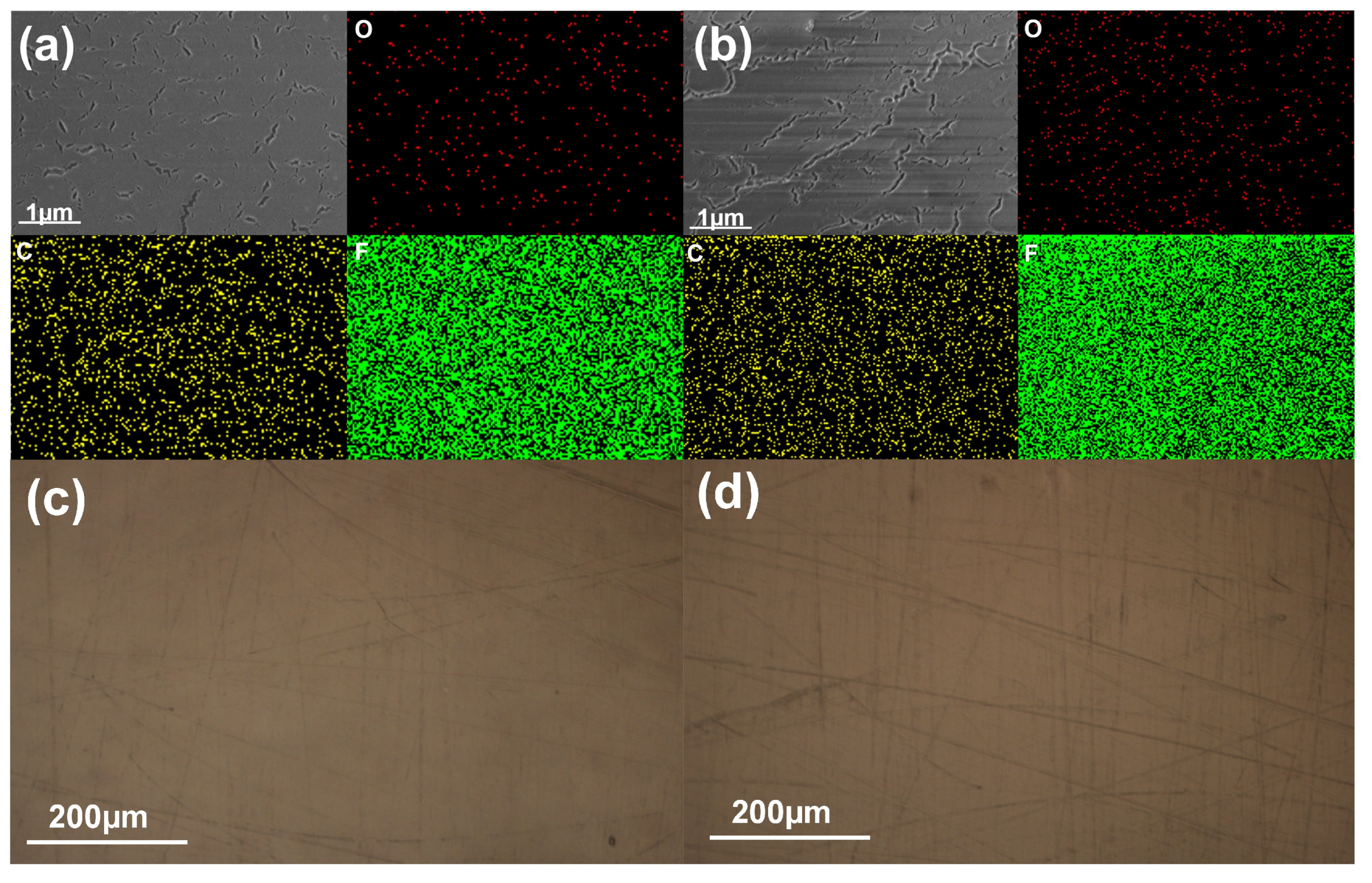
A series of material characterizations was conducted on S-O-M-TENG. Figure 2a shows the scanning electron microscopy (SEM) and energy-dispersive spectroscopy (EDS) images of pristine S-O-M-TENG, revealing microscopic cracks. Figure 2b displays the SEM and EDS images of the FEP surface after oil dropping, where microscopic cracks are observed due to mechanical stretching of commercial FEP tape during operation. Subsequent electrical tests confirm that these cracks do not affect the electrical output performance of S-O-M-TENG. EDS analysis indicates no significant differences in C, O, and F elemental compositions before and after use. Figure 2c,d present optical images of the surfaces under pristine and used conditions, respectively, demonstrating no visually apparent morphological changes between them.
Figures S13 and S14 present the SEM and EDS images of PTFE before and after operation, respectively. Both surfaces exhibit microcracks attributed to mechanical stretching during tape application. The EDS analysis reveals consistent elemental composition across both pre- and post-operation surfaces. Figures S15 and S16 show optical microscopy images of PTFE under identical conditions, demonstrating no discernible morphological differences.
Comparative infrared spectroscopy images (Figures S17 and S18) of FEP and PTFE surface characteristics before and after triboelectric testing confirm the absence of chemical reactions or surface contamination during operation. This evidence strongly indicates that the observed triboelectric effects are predominantly governed by electron transfer at the liquid-solid interface, rather than material degradation or chemical interactions.

3.1.3. Mechanism of S-O-M-TENG

In the experiment, the electrical output of the solid–oil TENG is collected by dripping oil on its surface. When the oil passes through the surface of the solid–oil TENG, the electrical output is generated. Figure 3a illustrates the working mechanism of S-O-M-TENG. As the oil droplet passes over the two upper electrodes, the voltage increases gradually with its downward movement. Upon contact with the additional electrode, the interfacial effect transitions to a bulk effect, resulting in a rapid voltage surge. When the droplet detaches from the additional electrode and moves past the lower electrodes, the voltage resumes a gradual increase as the droplet continues descending.
Figure 3 shows the working mechanism of the TENG with a modified electrode. The mechanism of this modification method is to transform the electrical signal by adjusting the number of electrodes despite the electrode area change. When the oil droplet touches the surface of FEP, it generates an induced charge; the oil droplet is positively charged while the FEP is negatively charged. As the oil droplet slides on the FEP, the oil droplet acquires more charge. When the oil droplet passes over the electrode, the electrode produces a corresponding negative charge, and when the oil droplet leaves the top of the electrode, the electrode produces the positive induced charge, thus generating an induced current. Figure S19 describes the working mechanism of the TENG with a modified polymer. The mechanism of this modification method is to transform the electrical signal by changing the solid–liquid contact area. When the oil droplet touches the surface of FEP, it generates an induced charge; the oil droplet is positively charged, and the FEP is negatively charged. When the oil droplet leaves the surface of FEP and contacts the aluminum foil electrode, the positive charge of the oil droplet and the negative charge of the electrode belt cancel each other, followed by an induced charge when it comes into contact with FEP. Figure S20 shows the working mechanism of TENG with an external electrode. When the oil droplet touches the surface of FEP, it generates an induced charge; the oil droplet is positively charged, and the FEP is negatively charged. When the oil droplet slides on the FEP, the oil droplet acquires more charge, and when the oil droplet touches the applied electrode, a current path is formed, and the interface effect is transformed into a bulk effect, which increases the electrical output.
The working principle can be divided into two stages. In the first stage, the liquid flows down. Firstly, the solid–liquid contact surface is negatively charged due to the contact between the liquid and the FEP material. Simultaneously, the positive charge in the liquid is attracted by the negative charge and converges in large quantities to form an electric double layer (EDL). As a result of the formation of the electric double layer, the positive charge in the liquid near the contact surface builds up and generates an electric field directed towards the contact surface, attracting the negative charge of the contact surface and repelling the positive charge. As a result, the positive charge on the outer electrode is repelled into the external circuit and transferred to the other electrode, while the negative charge is repelled and flows inside the liquid volume. In the second stage, the moment the liquid moves forward and touches the additional electrode, it is in full contact with the area covered by the additional electrode; then the huge air resistance disappears, and accordingly, the resistance of the entire circuit suddenly decreases. At this point, the circuit is equivalent to switching from an open circuit to a path. Under the influence of the positive charge of the additional electrode, an electric field and a new EDL are established, which attracts the negative charge in the liquid volume to move to the inner electrode and repels the positive charge inside the liquid to move to the FEP. During this phase, two EDLs are present at the same time, triggering the positive and negative charges in the liquid to move in a directional manner, which is equivalent to reducing the internal resistance of the liquid. Therefore, when the air internal resistance disappears and the liquid internal resistance decreases, higher electrical energy output is generated in the external circuit, which is the charge transfer principle of the bulk effect.
With a single electrode, the entire device functions as a single-electrode TENG. When the oil droplet contacts the FEP film, the droplet becomes positively charged while the FEP becomes negatively charged. As the droplet slides away, the electrode induces a corresponding negative charge, as shown in Figure 3b.
With two electrodes, the device can be viewed as two single-electrode TENGs that are connected in series. The working principle of each single-electrode TENG remains identical, as shown in Figure 3c.
With three electrodes (where the droplet diameter exceeds the spacing between electrodes), the device operates as one freestanding triboelectric-layer TENG and one single-electrode TENG connected in series. As the droplet transfers from the first to the second electrode, the negative charge on the first electrode gradually transfers to the second one. The first two electrodes function as a freestanding triboelectric-layer TENG, while the third electrode acts as a single-electrode TENG (Figure 3d).
With four electrodes, the device operates as two freestanding triboelectric-layer TENGs (Figure 3e).
With five electrodes, the device functions as two freestanding triboelectric-layer TENGs and one single-electrode TENG (Figure 3f).
Freestanding triboelectric-layer TENGs exhibit higher efficiency than single-electrode TENGs. Therefore, increasing the number of electrodes generally enhances the overall electrical output signal of the device. However, with five electrodes, the additional single-electrode TENG impairs the output performance of the freestanding-layer TENGs. Consequently, the strongest electrical signal output is achieved with four electrodes.

3.1.4. Application of S-O-M-TENG

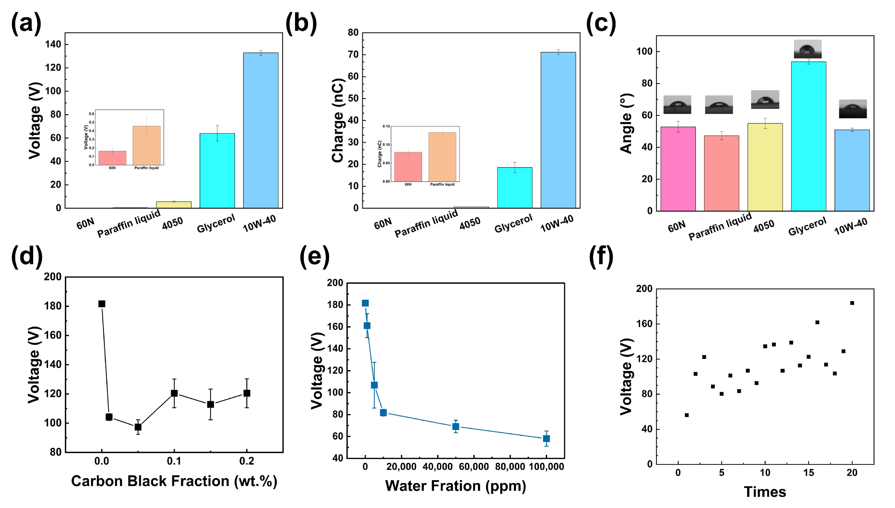
The electrical outputs of S-O-M-TENG are characterized for five different oils: 60 N base oil, paraffin oil, 4050 aerospace oil, glycerol, and 10 W-40 lubricant. Figure 4a–c shows the voltage output, current output, and contact angle for 60 N base oil, paraffin oil, 4050 aerospace oil, glycerol, and 10 W-40 lubricant from left to right, respectively. Figure 4a shows their voltage outputs as 0.16 V, 0.45 V, 5.61 V, 64.01 V, and 132.84 V, respectively, while Figure 4b presents their charge outputs as 0.08 nC, 0.13 nC, 0.59 nC, 18.56 nC, and 71.11 nC. These distinct electrical responses to different oils endow S-O-M-TENG with the ability to monitor oil leakage in real time. Figure 4c displays the contact angles of five oils on FEP surfaces: 52.8°, 47.2°, 55.1°, 93.7°, and 51.1°, corresponding to 60 N base oil, paraffin oil, 4050 aerospace oil, glycerol, and 10 W-40 lubricant, respectively. Despite similar contact angles for four oils (excluding glycerol), their electrical outputs exhibit no direct correlation with wettability. The reduced performance of the first three oils arises from their high electrical conductivity, which promotes charge leakage through conductive liquid pathways even when electron transfer occurs at the interface. Additionally, their low dielectric constants (~2–3) limit charge storage capacity and weaken the interfacial electric field during separation, further suppressing voltage generation. The low viscosities (~10 mPa·s) of 60 N base oil and paraffin oil exacerbate this issue by inducing premature liquid-FEP separation, thereby truncating effective charge transfer. Although 4050 aerospace oil demonstrates moderate viscosity, its unfavorable dielectric and conductive properties remain critical limiting factors.
Glycerol, despite having the largest contact angle (93.7°), exhibits suboptimal output because its extreme viscosity (~1.412 Pa·s) impedes rapid liquid retraction. This slow separation allows charge recombination during prolonged interfacial contact, while poor wettability reduces the effective solid–liquid contact area. In contrast, 10 W-40 lubricant achieves the highest voltage output despite its intermediate contact angle (51.1°), which is attributed to its balanced dielectric constant (~3–5), inclusion of insulating additives to suppress charge leakage, and an optimal viscosity (~0.1 Pa·s). These properties collectively enable sustained interfacial contact for sufficient charge transfer while ensuring timely separation to preserve electrostatic potential.
The systematic comparison confirms that triboelectric performance is governed not only by wettability but also by the synergistic interplay of dielectric properties, conductivity, and viscosity. These factors collectively regulate charge transfer efficiency, retention, and interfacial dynamics during solid–liquid interactions. Contact angle measurements were performed on the FEP surface with various oils after multiple testing cycles, yielding values of 44.7°, 43.8°, 51.6°, 85.4°, and 44.7° (Figure S21). The stability of these contact angles before and after testing confirms the robust performance of the material.
Subsequently, 10 W-40 lubricant (exhibiting the strongest output) is modified by varied carbon and water contents to analyze the impurity detection capabilities (Figure 4d,e). Results indicate that the electrical output decreases with carbon incorporation and stabilizes as carbon content increases. Conversely, higher water content progressively reduces the output signal. This demonstrates S-O-M-TENG’s ability to detect impurity levels in lubricants.
Figure 4f demonstrates the cyclic stability of S-O-M-TENG over 20 operational cycles, with voltage outputs consistently maintained around 120 V. This remarkable stability confirms its suitability for practical applications in monitoring lubricant leakage and detecting contaminants in oil systems.

4. Conclusions

In this study, the S-O-M-TENG for monitoring lubricating oil is based on the triboelectric effect at the solid–oil interface. The solid–oil TENG, modified to optimize the highest electrical output, achieves a voltage of up to 132.84 V in real time for oil leakage and a charge density of 142.22 uC·m−2, and the maximum output power of 3.10 μW during the process of oil contacting and separating from the device surface, which has marvelous electrical output performance. Simultaneously, the S-O-M-TENG detects the impurity content in the lubricating oil. Therefore, the S-O-M-TENG designed in this study can monitor oil leakage in real time and detect the impurity content in lubricating oil.

Supplementary Materials

The following supporting information can be downloaded at: https://www.mdpi.com/article/10.3390/nanoenergyadv5040015/s1, Figure S1: Structure of solid-oil TENG; Figure S2: Modified electrode of solid-oil TENG; Figure S3: Modified polymer of solid-oil TENG; Figure S4: Add electrode of solid-oil TENG; Figure S5: Voltage after modifying electrode; Figure S6: Charge after modifying electrode; Figure S7: Voltage modifying polymer; Figure S8: Charge after modifying polymer; Figure S9: Voltage after adding electrode; Figure S10: Charge after adding electrode; Figure S11: Voltage modifying polymer; Figure S12: Charge after modifying polymer; Figure S13: SEM and EDS images before use; Figure S14: SEM and EDS images after use; Figure S15: Optical microscope morphologies before use; Figure S16: Optical microscope morphologies after use; Figure S17: FTIR characterization of FEP surfaces prior to and following oil contact; Figure S18: FTIR characterization of PTFE surfaces prior to and following oil contact; Figure S19: The working mechanism of the modification method of the modified polymer; Figure S20: The working mechanism of the modification method of the external electrode; Figure S21: Contact angles of various oils on the FEP surface after multiple tests.

Author Contributions

Conceptualization, S.L.; Methodology, S.L.; Experiment, Y.L.; Writing—Original Draft Preparation, Y.L.; Writing—Review and Editing, H.Z. and Z.G.; Supervision, S.L.; Project Administration, S.L. All authors have read and agreed to the published version of the manuscript.

Funding

This project is supported by the National Natural Science Foundation of China (Grant No. 2240090560); the Doctoral Research Startup Fund of Liaoning Province (No. 2025BS0211); the Beijing Key Laboratory of High-Entropy Energy Materials and Devices, Beijing Institute of Nanoenergy and Nanosystems (No. GS2025MS017); the Fundamental Research Funds for the Central Universities (No. 3132025172); and the Start-up Funds for Talent Research (02502439).

Data Availability Statement

The original contributions presented in this study are included in the article/Supplementary Materials. Further inquiries can be directed to the corresponding author.

Conflicts of Interest

The authors declare no conflicts of interest.

Abbreviations

The following abbreviations are used in this manuscript:
TENGTriboelectric Nanogenerator
S-L-TENGSolid–liquid Triboelectric Nanogenerators
S-O-M-TENGSolid–oil Triboelectric Nanogenerators
FEPFluorinated ethylene propylene
PTFEPolytetra-fluoroethylene
PMMAPoly methyl methacrylate

References

  1. Yang, S.; Cao, N.; Yu, B. Wear debris measurement in lubricating oil based on inductive method: A review. Meas. Control 2023, 56, 1422–1435. [Google Scholar] [CrossRef]
  2. Ren, C.; Zhang, X.; Jia, M.; Ma, C.; Li, J.; Shi, M.; Niu, Y. Antifoaming agent for lubricating oil: Preparation, mechanism and application. Molecules 2023, 28, 3152. [Google Scholar] [CrossRef]
  3. Wang, Y.; Chen, Y.; Liang, X.; Tan, P.; Deng, S. Impacts of lubricating oil and its formulations on diesel engine particle characteristics. Combust. Flame 2021, 225, 48–56. [Google Scholar] [CrossRef]
  4. Domínguez-García, S.; Maya-Yescas, R.; Béjar-Gómez, L. Reduction of lubricant life in lubrication systems for internal combustion engines due to high lubricant supply rates. Mater. Lett. 2022, 313, 131785. [Google Scholar] [CrossRef]
  5. Wang, K.; Sun, Y.; Zhang, H.; Ding, Z.; Song, W.; Li, J. Self-sensing smart thrust roller bearing based on triboelectric nanogenerator with highly sensitivity for monitoring trace contaminants in lubricating oil. Nano Energy 2024, 119, 109058. [Google Scholar] [CrossRef]
  6. Raţiu, S.; Josan, A.; Alexa, V.; Cioată, V.G.; Kiss, I. Impact of contaminants on engine oil: A review. J. Phys. Conf. Ser. IOP Publ. 2021, 1781, 012051. [Google Scholar] [CrossRef]
  7. Singh, A.; Verma, N.; Mamatha, T.; Kumar, A.; Singh, S.; Kumar, K. Properties, functions and applications of commonly used lubricant additives: A review. Mater. Today Proc. 2021, 44, 5018–5022. [Google Scholar] [CrossRef]
  8. Domínguez-García, S.; Béjar-Gómez, L.; López-Velázquez, A.; Maya-Yescas, R.; Nápoles-Rivera, F. Maximizing lubricant life for internal combustion engines. Processes 2022, 10, 2070. [Google Scholar] [CrossRef]
  9. Stępień, Z. Premature degradation of lubricating oil during the service life of the positive-ignition engine. Tribol. Online 2021, 16, 31–37. [Google Scholar] [CrossRef]
  10. Shah, R.; Woydt, M.; Zhang, S. The economic and environmental significance of sustainable lubricants. Lubricants 2021, 9, 21. [Google Scholar] [CrossRef]
  11. Park, G.; Cudney, H.H.; Inman, D.J. Feasibility of using impedance-based damage assessment for pipeline structures. Earthq. Eng. Struct. Dyn. 2001, 30, 1463–1474. [Google Scholar] [CrossRef]
  12. Martini, A.; Troncossi, M.; Rivola, A. Leak detection in water-filled small-diameter polyethylene pipes by means of acoustic emission measurements. Appl. Sci. 2016, 7, 2. [Google Scholar] [CrossRef]
  13. Tanimola, F.; Hill, D. Distributed fibre optic sensors for pipeline protection. J. Nat. Gas Sci. Eng. 2009, 1, 134–143. [Google Scholar] [CrossRef]
  14. Wang, Z.L. From contact electrification to triboelectric nanogenerators. Rep. Prog. Phys. 2021, 84, 096502. [Google Scholar] [CrossRef] [PubMed]
  15. Wang, S.; Xu, P.; Liu, J.; Wang, H.; Si, J.; Deng, J.; Xu, M.; Wang, Z.L. Underwater triboelectric nanogenerator. Nano Energy 2023, 118, 109018. [Google Scholar] [CrossRef]
  16. Chung, S.H.; Chung, J.; Lee, S. Recent advances in lubricant-based triboelectric nanogenerators for enhancing mechanical lifespan and electrical output. Nanoenergy Adv. 2022, 2, 210–221. [Google Scholar] [CrossRef]
  17. Wang, H.; Xu, L.; Wang, Z. Advances of high-performance triboelectric nanogenerators for blue energy harvesting. Nanoenergy Adv. 2021, 1, 32–57. [Google Scholar] [CrossRef]
  18. Ding, Z.; Wang, X.; Huang, C.; Choi, K.; Choi, D. Advances in intelligent sports based on triboelectric nanogenerators. Nanoenergy Adv. 2024, 4, 258–283. [Google Scholar] [CrossRef]
  19. Dong, X.; Liu, Z.; Yang, P.; Chen, X. Harvesting wind energy based on triboelectric nanogenerators. Nanoenergy Adv. 2022, 2, 245–268. [Google Scholar] [CrossRef]
  20. Liu, L.; Hu, T.; Zhao, X.; Lee, C. Recent progress in blue energy harvesting based on triboelectric nanogenerators. Nanoenergy Adv. 2024, 4, 156–173. [Google Scholar] [CrossRef]
  21. Kaja, K.R.; Hajra, S.; Panda, S.; Belal, M.; Nam, S.; Pakawanit, P.; Panigrahi, B.K.; Khanbareh, H.; Bowen, C.; Yu, J.; et al. Waste Polyethylene-Coated Fabrics for Dual-Mode Interfaces Triboelectrification for Self-Powered Sensors. Results Eng. 2025, 107111. [Google Scholar] [CrossRef]
  22. Kaja, K.R.; Hajra, S.; Panda, S.; Belal, M.A.; Pharino, U.; Khanbareh, H.; Vittayakorn, N.; Vivekananthan, V.; Bowen, C.; Kim, H.J. Exploring liquid-solid interface based triboelectrification, structures, and applications. Nano Energy 2024, 131, 110319. [Google Scholar] [CrossRef]
  23. Kaja, K.R.; Hajra, S.; Panda, S.; Belal, M.A.; Pakawanit, P.; Vittayakorn, N.; Bowen, C.; Khanbareh, H.; Kim, H.J. Triboelectrification based on the waste waterproof textiles for multisource energy harvesting. Adv. Sustain. Syst. 2025, 9, 2400678. [Google Scholar] [CrossRef]
  24. Chen, P.; Zhang, Z.; Ye, C.; Jiang, Y.; Chen, L.; Xu, Z.; Xu, M.; Hong, Z.; Jiang, T.; Wang, Z.L. A Self-Sustainable, Ultrarobust and High-Power-Density Triboelectric Nanogenerator for In Situ Powering of Marine Internet of Things. Adv. Mater. 2025, 37, e11283. [Google Scholar] [CrossRef]
  25. Nie, J.; Ren, Z.; Xu, L.; Lin, S.; Zhan, F.; Chen, X.; Wang, Z.L. Probing contactelectrification-induced electron and ion transfers at a liquid-solid interface. Adv. Mater. 2020, 32, 1905696. [Google Scholar] [CrossRef] [PubMed]
  26. Zhao, J.; Wang, D.; Zhang, F.; Liu, Y.; Chen, B.; Wang, Z.L.; Pan, J.; Larsson, R.; Shi, Y. Real-time and online lubricating oil condition monitoring enabled by triboelectric nanogenerator. ACS Nano 2021, 15, 11869–11879. [Google Scholar] [CrossRef] [PubMed]
  27. Xu, W.; Zheng, H.; Liu, Y.; Zhou, X.; Zhang, C.; Song, Y.; Deng, X.; Leung, M.; Yang, Z.; Xu, R.X.; et al. A droplet-based electricity generator with high instantaneous power density. Nature 2020, 578, 392–396. [Google Scholar] [CrossRef]
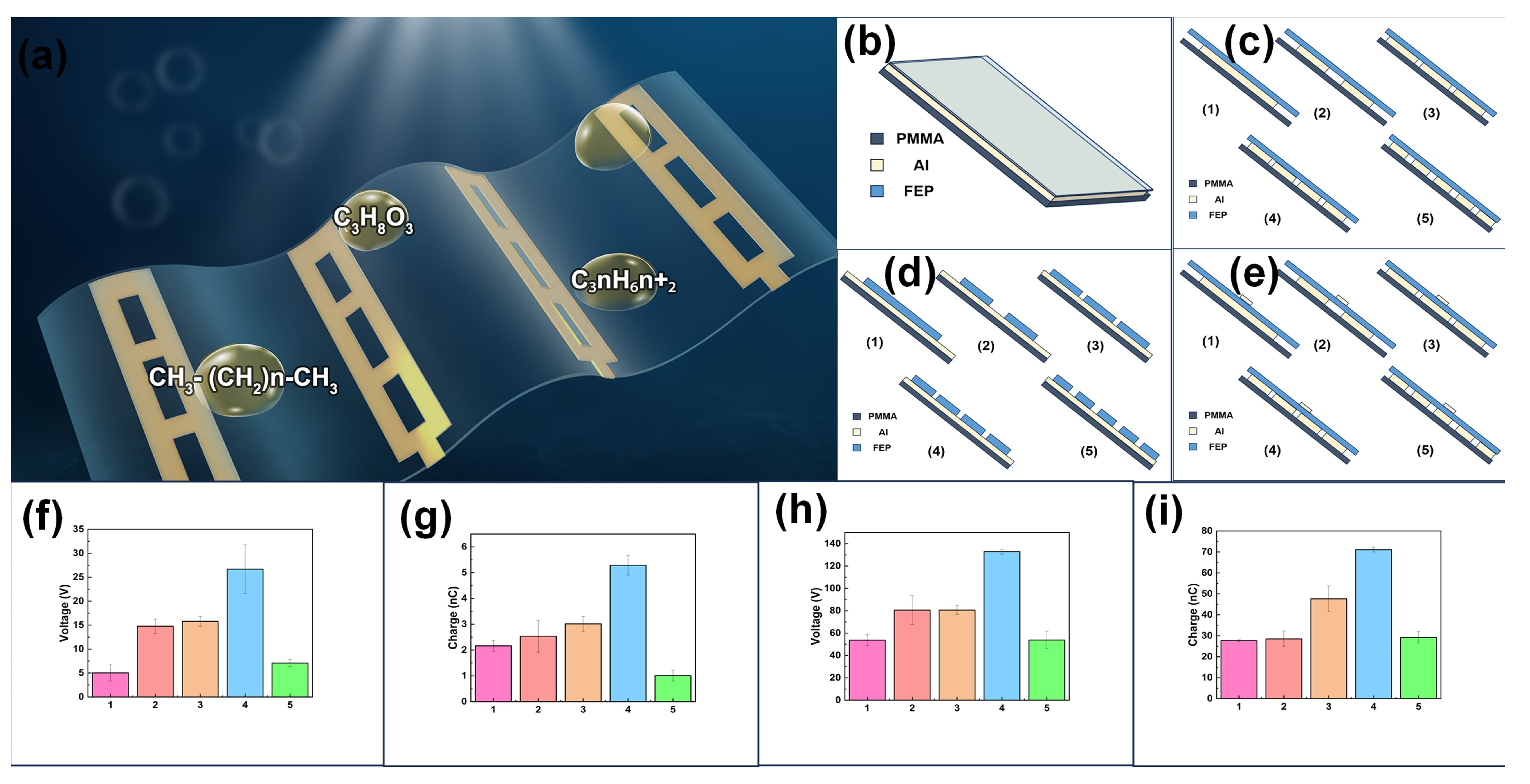
Figure 1. Structure and modification of solid–oil TENGs. (a) Diagram of solid–oil TENG. Structure of solid–oil TENG (b), modified electrode (c), modified polymer (d), and added electrode (e) of solid–oil TENG. (f) Voltage and (g) charge after modifying the electrode. (h) Voltage and (i) charge after adding the electrode.
Nanoenergyadv 05 00015 g001
Figure 2. Material characterization of S-O-M-TENG. SEM and EDS images of S-O-M-TENG (a) before use and (b) after use. Optical microscope images of S-O-M-TENG (c) before use and (d) after use.
Nanoenergyadv 05 00015 g002
Figure 3. The working mechanism of various retrofit methods. (a) Mechanism of S-O-M-TENG. (b) the working mechanism of one electrode, (c) two electrodes, (d) three electrodes, (e) four electrodes, and (f) five electrodes.
Nanoenergyadv 05 00015 g003
Figure 4. Application of S-O-M-TENG. (a) The voltage of different oils. (b) The charge of different oils. (c) The contact angle of different oils. Voltage with (d) different carbon content and (e) different water content. (f) Output characteristic after 20 times.
Nanoenergyadv 05 00015 g004
Disclaimer/Publisher’s Note: The statements, opinions and data contained in all publications are solely those of the individual author(s) and contributor(s) and not of MDPI and/or the editor(s). MDPI and/or the editor(s) disclaim responsibility for any injury to people or property resulting from any ideas, methods, instructions or products referred to in the content.