Article

Electronic Structure Regulation Enhances the Urea Oxidation Reaction Performance of the NiCo-MOF Catalyst

by
Lang Yao
,
Yanzhi Yang
,
Sirong Li
and
Xuechun Xiao
*
School of Materials and Energy, Yunnan University, Kunming 650091, China
*
Author to whom correspondence should be addressed.
Nanoenergy Adv. 2025, 5(4), 17; https://doi.org/10.3390/nanoenergyadv5040017 (registering DOI)
Submission received: 27 August 2025 / Revised: 4 October 2025 / Accepted: 3 November 2025 / Published: 6 November 2025
(This article belongs to the Special Issue Hybrid Energy Storage Systems Based on Nanostructured Materials)

Abstract

In this paper, spherical-shaped catalytic materials with needle-like stacking structures were synthesized in situ on the foam nickel substrate using the hydrothermal method, resulting in the NiM (M = Co, Mn, W, Zn)-MOF series. Furthermore, the catalyst with the best performance was obtained by adjusting the ratio of metal elements. Electrochemical tests show that NiCo-MOF (Ni: Co = 1:2) has the best electrocatalytic performance. During the UOR process, NiCo-MOF exhibits the optimal performance in 1 M KOH and 0.5 M urea solution, with a potential of only 1.33 V at a current density of 10 mA/cm2. The improvement in the activity of NiCo-MOF can be attributed to the synergistic effect between the Ni and Co bimetals, which leads to an increase in the electron transfer rate, the exposure of active sites, and an improvement in conductivity. Moreover, metal–organic framework materials are widely used as electrocatalysts due to their compositional diversity, rich pore structures, and high specific surface areas. Meanwhile, NiCo-MOF was used as a UOR and HER catalyst to assist the overall water decomposition with urea, and it showed relatively excellent performance. Only a voltage of 1.56 V was required to drive the current density of 10 mA/cm2 of the UOR || HER system. Therefore, the synthesized NiCo-MOF catalyst plays an important role in improving the efficiency of hydrogen production from water electrolysis and has promising sustainable application prospects.

1. Introduction

With the continuous growth of the population, industry and agriculture are also developing rapidly, and the demand for technology and energy is constantly increasing. However, fossil fuels such as petroleum, coal, and natural gas are non-sustainable energy sources, and the use of these energy sources can lead to problems such as environmental deterioration [1,2]. Therefore, it is of great significance to conduct research and exploration on renewable energy sources. Hydrogen energy has received extensive attention due to its advantages, such as its high calorific value, high energy density, and pollution-free combustion process [3,4]. There are many methods for producing hydrogen energy, but traditional hydrogen production methods consume a large amount of energy and cause environmental pollution [5]. Therefore, currently, hydrogen is mainly produced through the water electrolysis method, which consists of the oxygen evolution reaction (OER) at the anode and the hydrogen evolution reaction (HER) at the cathode [6,7]. Since the oxygen evolution reaction involves a four-electron transfer process with a theoretical potential of 1.23 V vs. RHE, it has a high reaction energy barrier and slow reaction kinetics. These factors have become the key issues in the research of hydrogen production by water electrolysis [8,9]. To improve the efficiency of hydrogen production, it has been found that molecules such as urea, methanol, and ethanol can be oxidized at a relatively fast reaction rate, which can concentrate the reaction kinetics in the electrolytic cell to reduce energy consumption [10]. Among them, the urea oxidation reaction (UOR) is particularly prominent. The urea oxidation reaction can replace OER as an ideal anodic reaction due to its lower theoretical potential (0.37 V vs. RHE) [11]. Moreover, the UOR can effectively treat urea-rich wastewater, which not only improves the conversion efficiency but also protects the environment [12]. In addition, in an alkaline electrolyte, the products of electro-catalytic urea decomposition are N2 and CO2, which can avoid the explosion caused by the mixing of H2 and O2 and improve the safety of the experiment. However, the UOR still involves a six-electron transfer process (CO(NH2)2 + 6OH → N2 + CO2 + 5H2O + 6e), and its thermodynamics and kinetics are relatively slow. Therefore, efficient catalysts are needed to accelerate the reaction and improve the electro-catalytic reaction performance [13,14].
To lower the reaction barrier of UOR, some catalysts with excellent performance have been developed. Among them, the relatively active catalysts are noble metals or their derivatives containing Pt, Pd, and Ir [15]. However, their scarcity and high cost greatly limit their widespread use. Therefore, the rational design and exploration of environmentally friendly, efficient, and low-cost catalysts have become the research focus [16]. Among them, nickel-based catalysts (including oxides, hydroxides, sulfides, nitrides, and alloys) are considered the most ideal UOR catalysts to replace noble-metal catalysts [17,18]. In 2009, the Boggs [19] team first proposed a technology that uses transition-metal nickel-based catalysts to oxidize urea to produce hydrogen through electrochemical oxidation. They found that the onset potential of the UOR is the same as that of the oxidation of Ni(OH)2 to NiOOH, indicating that the NiOOH generated in situ on the catalyst surface is the active center for the UOR. Since then, the research on urea electrolysis has shifted from the biological field to the field of electro-catalytic hydrogen production. Even though some progress has been made in the research of nickel-based catalysts, there is still much room for improvement in enhancing the performance and stability of these nickel-based catalysts [20,21].
For single-metal nickel catalysts, better catalytic performance can be obtained if they are combined with other transition metals to form bimetallic or multi-metallic catalysts [22,23]. Adding the metal element M (M = Co, Mn, W, Zn) to the nickel-based catalyst to form a nickel-based bimetallic catalyst can improve electrical conductivity. The synergistic effect between Ni and M (M = Co, Mn, W, Zn) changes the electronic structure of the catalyst. During the UOR process, Co2+/Co3+ enhances electron transfer, promotes the formation of more active substances NiOOH, and reduces the over-potential [24]. In addition, the combination of the two metals optimizes the electronic structure of the catalyst surface, balances the adsorption energy of intermediates, and improves the reaction kinetics [25]. Therefore, the number of active centers in the reaction can be increased through electronic regulation, and ultimately, the catalytic activity of the catalyst can be significantly improved [26]. For example, Yin et al. [27] introduced Fe3+ by soaking Ni@NCS in a K3[Fe(CN)6] solution. The incorporation of Fe3+ reduces the initial oxidation potential of urea, the reaction activation energy, and the reaction resistance, and induces the formation of more UOR active centers, Ni3+. These changes also lead to the generation of more electronic states, improving the adsorption energy of reactant and product molecules on the surface, which is beneficial to the UOR kinetics.
Metal–organic frameworks (MOFs) are a new type of porous material, formed by the combination of metal ions and organic ligands. Due to their characteristics such as a large specific surface area, diverse material morphologies, and regular pore structures, they have shown certain development in fields such as energy storage, gas adsorption, and catalysis [28,29]. Wang et al. [30] synthesized an MOF-based electrocatalyst NiFe-MIL-D@NF using the organic ligand terephthalic acid. The characteristics of abundant pore channels, high specific surface area, and diverse morphologies enhance the electrocatalytic activity of the NiFe-MIL-D@NF catalytic material. It only requires an overpotential of 394 mV to provide a current density of 100 mA·cm−2 in the OER and has excellent electrochemical stability.
Therefore, in this paper, Ni-based foam substrates were used to synthesize NiM (M = Co, Mn, W, Zn)-MOF series catalytic materials through in situ hydrothermal growth with a needle-like stacking structure. The nickel foam (NF) substrate has a three-dimensional porous structure with interconnected networks, excellent electrical conductivity, and good corrosion resistance. It can shorten the charge transfer path, avoid the use of polymer binders to fix the electrocatalyst, reduce the series resistance, and thus improve the activity and stability of the catalytic materials [31]. Using the catalytic material as the working electrode, linear sweep voltammetry, cyclic voltammetry, electrochemical impedance spectroscopy, and chronoamperometry tests were carried out in the presence and absence of urea, respectively. Finally, full-water splitting experimental tests were conducted with the catalytic material serving as the cathode and anode, respectively. The electronic regulation effect of the introduction of different transition metals M on the active centers of the NiOOH reaction was systematically explored. The influence of different Co doping amounts on the UOR performance was further studied. When Ni:Co = 1:2, the catalyst exhibited the best catalytic activity. At a current density of 10 mA cm−2, the required UOR potential was as low as 1.33 V, and it also had good stability. The NiM (M = Co, Mn, W, Zn)-MOF catalytic materials with excellent catalytic activity and stability for urea-assisted overall water splitting obtained in this study provide a reference value for the development of new nickel-based MOF catalytic materials.

2. Experimental

2.1. Chemical Reagents

Nickel(II) chloride hexahydrate (NiCl2·6H2O), cobalt(II) chloride hexahydrate (CoCl2·6H2O), manganese(II) chloride tetrahydrate (MnCl2·4H2O), sodium tungstate dihydrate (Na2WO4·2H2O), zinc nitrate hexahydrate (Zn(NO3)2·6H2O), hydrochloric acid (HCl), 2,5-dihydroxyterephthalic acid (DHTA), N,N-dimethylformamide (DMF), and absolute ethanol (C2H5OH) were purchased from Sinopharm Chemical Reagent Co., Ltd (Shanghai, China). The deionized water (18.2 MΩ cm) used in the experiments was purified by a ZYPFT-2-20T system (Sichuan Zhuoyue Water Treatment Equipment Co., Ltd., Chengdu, China). All products could be used without further purification.

2.2. Pretreatment of Nickel Foam

The NF samples (1 cm × 2 cm) were successively sonicated in HCl, ethanol, and deionized water for 30 min to remove surface oils and oxides. Subsequently, the cleaned NF samples were placed in a vacuum oven and dried at 60 °C for 12 h to obtain uncontaminated nickel foam.

2.3. Preparation of NiM (M = Co, Mn, W, Zn)-MOF Catalyst

The NiM (M = Co, Mn, W, Zn)-MOF catalysts were in situ prepared on nickel foam by a hydrothermal method, as shown in Figure 1a. First, 0.65 mmol of NiCl2·6H2O, 1.3 mmol of CoCl2·6H2O, and 0.48 mmol of 2,5-dihydroxyterephthalic acid were added to a mixture of 20 mL of N,N-dimethylformamide (DMF), 2 mL of ethanol, and 2 mL of deionized water, and then the mixture was stirred by a magnetic stirrer for 30 min until completely dissolved. After stirring, the solution was sealed in a Teflon-lined autoclave with the pre-treated nickel foam placed inside. The autoclave was maintained at 140 °C for 14 h. After naturally cooling to room temperature, the nickel foam loaded with NiCo-MOF was repeatedly washed with ethanol and finally dried in a vacuum at 60 °C for 12 h to obtain NiCo-MOF.
The synthesis of NiM (M = Mn, W, Zn) follows a procedure analogous to that of NiCo-MOF, with the sole exception being the substitution of CoCl2·6H2O with MnCl2·4H2O, Na2WO4·2H2O, and Zn(NO3)2·6H2O during the synthesis.
To investigate the influence of different amounts of Co on the performance of NiCo-MOF, the addition amounts of CoCl2·6H2O were set as 0.65 mmol, 0.97 mmol, 1.3 mmol, and 1.63 mmol, forming four ratios with the addition amount of NiCl2·6H2O. Four NiCo-MOF catalysts with different ratios were prepared and named as NiCo-MOF—2:2, NiCo-MOF—2:3, NiCo-MOF—2:4, and NiCo-MOF—2:5, respectively.

2.4. Characterization of Materials

In this experiment, the phase characterization of the synthesized samples was carried out using a D/MAX-3B X-ray diffractometer produced by Rigaku Corporation in Akishima-shi, Japan, with a scanning range from 10° to 90°. The surface morphology and elemental distribution were analyzed using a Nova Nanosem 450 field-emission scanning electron microscope produced by FEI Company in Hillsboro, OR, USA. The morphology and selected-area electron diffraction (SAED) analysis of the materials were conducted using a JEM-2100 (UHR) transmission electron microscope produced by JEOL Ltd., Tokyo, Japan. The elemental and valence-state analysis of the materials was performed using a PHI 5500 X-ray photoelectron spectrometer produced by PHI Company in Houma, LA, USA, with Al/Mg as the dual-anode target materials.

2.5. Electrochemical Characterization

All electrochemical data were measured at room temperature using a conventional three-electrode system on a CHI760E electrochemical workstation (Chenhua Instrument Co., Ltd., Shanghai, China). Among them, the catalyst prepared above served as the working electrode, a platinum plate as the counter electrode, and a Hg/HgO electrode as the reference electrode. All electrochemical potentials were converted to the potentials relative to the reversible hydrogen electrode (vs. RHE) using Equation (1). The electrochemical performance of the electrodes was tested in 1 M KOH solution with and without 0.5 M urea. Unless otherwise specified, the IR compensation for the LSV test was 90%, and the scan rates for both CV and LSV tests were 5 mV s−1.
E(RHE) = E(Hg/HgO) + 0.059 × PH + 0.098
Prior to the experiment, N2 was purged into the electrolyte for 30 min to achieve saturation, thereby eliminating interference from O2. The Tafel slope was obtained by fitting the Tafel equation (Equation (2)), where η denotes the overpotential, j represents the current density, b is the Tafel slope, and a is a constant.
η = b log j + a
The double-layer capacitance (Cdl) was determined within a potential range of 0.2–0.3 V (vs. RHE) at scan rates of 20–100 mV s−1 to establish the linear relationship between the scan rate and current density. The calculation formula (Equation (3)) is given as follows, where v is the scan rate in cyclic voltammetry, and ja and jc represent the anodic and cathodic current densities, respectively, at 0.25 V (vs. RHE) obtained from the fitted cyclic voltammetry curves. Electrochemical impedance spectroscopy (EIS) measurements were performed over a frequency range of 0.01 Hz to 105 Hz.
Cdl = |jajc| 2v

3. Results and Discussion

3.1. Characterization of the Sample

To determine the crystallographic orientation of the samples, XRD measurements were performed on four groups of samples. As shown in Figure 1b, the XRD pattern of the material shows excellent agreement with the simulated pattern from the CCDC database (CCDC number: 1494752). The diffraction pattern of NiCo-MOF shows characteristic peaks at 2θ = 11.9°, 13.7°, 21.7°, 24.8°, 31.5°, 34.5° and 41.2°, corresponding to (300), (220), (321), (241), (621), (152) and (452), respectively. This proves the successful preparation of the Ni-based-MOF catalytic material. Some impurity peaks can be observed in the diffraction pattern because, during the hydrothermal synthesis process, some metal ions may be oxidized or hydrolyzed to form oxides (NiOOH), especially under alkaline or high-temperature conditions. Therefore, the XRD data can be seen to match PDF#06-00754. NiOOH is also an active site for the urea oxidation reaction, which can increase the intrinsic activity of the catalyst and improve the catalytic efficiency. Compared with NiMn-MOF, NiW-MOF, and NiZn-MOF, the NiCo-MOF catalyst exhibits lower diffraction peak intensities, which may be attributed to the different synergistic effects between Ni and various doping elements. The NiCo-MOF may have formed smaller-sized grains or thinner needle-like structures (high specific surface area is usually accompanied by smaller grain sizes and more defects), resulting in a decrease in the intensity of the diffraction peaks. Additionally, the introduction of Co in the Ni lattice introduces more defects or lattice distortions. Although this is beneficial for catalytic activity, it reduces the long-range order and thereby weakens the XRD diffraction intensity.
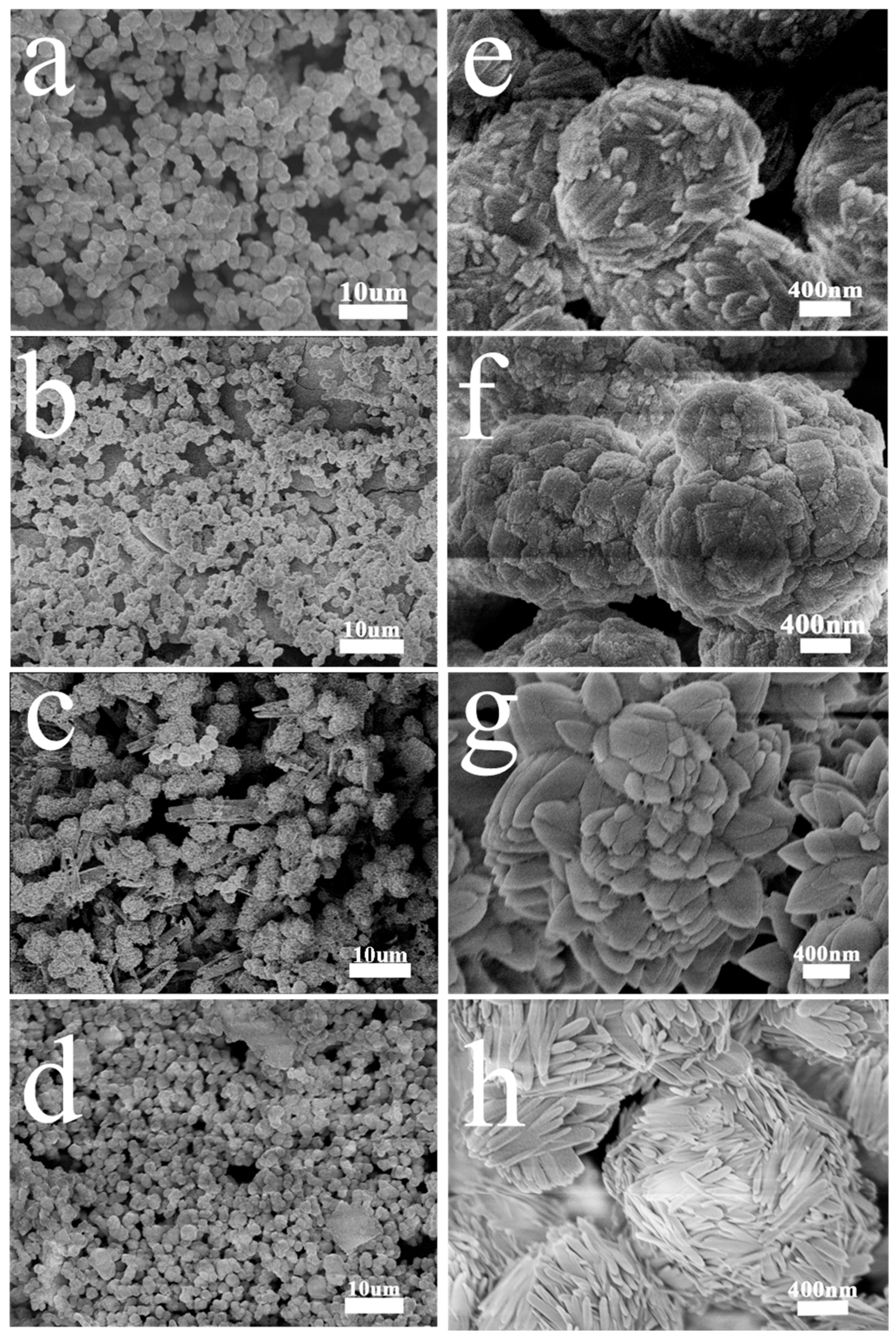
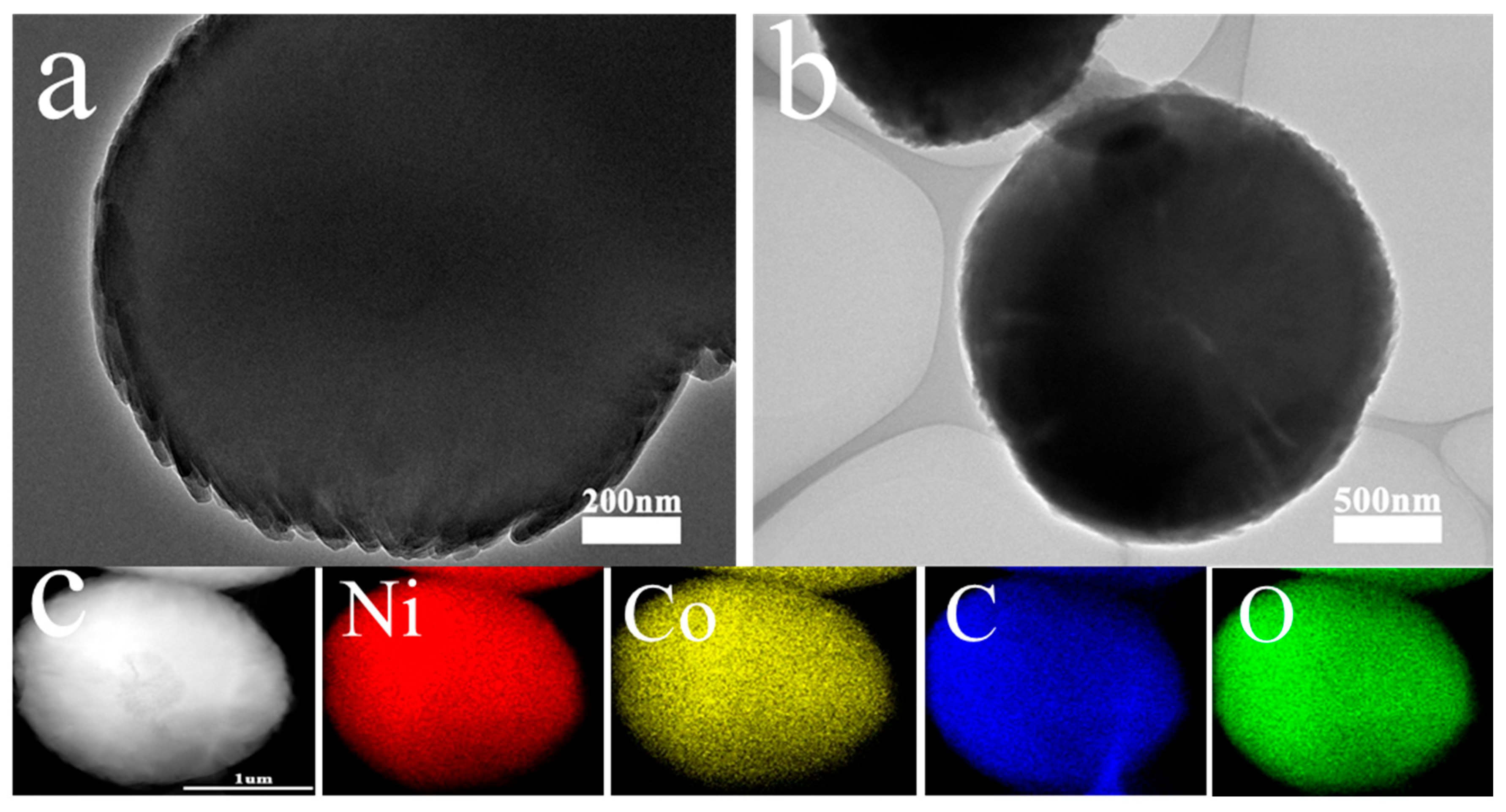
The morphology and structure of NiM (M = Co, Mn, W, Zn)-MOF catalysts were characterized using scanning electron microscopy (SEM) and transmission electron microscopy (TEM). Figure 2a,e reveal that NiMn-MOF exhibits a spherical structure composed of stacked nanosheets, while Figure 2b,f demonstrate that NiW-MOF displays a pinecone-like spherical morphology. Figure 2c,g show that NiZn-MOF possesses a petal-like structure formed by stacked nanosheets. As shown in Figure 2d,h, NiCo-MOF primarily exhibits a spherical structure formed by needle-like stacks, indicating that the introduction of different transition metals significantly influences the morphology of NiM-MOF catalysts. Due to their similar atomic radii, Co atoms can readily incorporate into the Ni lattice during synthesis, forming a relatively stable crystal structure that enhances the catalyst’s stability [32]. Compared with NiM (M = Co, Mn, W, Zn)-MOF catalysts, the needle-like stacks formed by Co incorporation provide additional anchoring sites for active centers, facilitating faster electron transfer. This modification of the electronic structure ultimately enhances the overall catalytic performance [33,34]. TEM images (Figure 3a,b) further confirm the spherical microstructure of the NiCo-MOF catalyst, consistent with the SEM observations. Furthermore, the elemental mapping (Figure 3c) and EDS spectrum (Figure S1) reveal the uniform distribution of Ni, Co, O, and C elements on the material surface, confirming the successful synthesis of the NiCo-MOF catalyst via the hydrothermal method.
To further investigate the surface elemental valence states of NiM (M = Co, Mn, W, Zn)-MOF catalysts, X-ray photoelectron spectroscopy (XPS) characterization was performed to obtain information about the elemental distribution and valence states on the catalyst surfaces. Figure 4a displays the survey spectra of NiM (M = Co, Mn, W, Zn)-MOF catalysts, consisting of Ni 2p, C 1s, O 1s, and corresponding elemental signals, confirming the successful preparation of the catalytic materials. As shown in the Ni 2p spectra (Figure 4b), all four samples exhibit coexistence of Ni2+ and Ni3+ states. For NiM (M = Co, Mn, W, Zn)-MOF, the characteristic peaks at approximately 855.38 eV and 872.98 eV correspond to Ni2+ 2p3/2 and 2p1/2, respectively, while those at 856.58 eV and 874.68 eV are attributed to Ni3+ 2p3/2 and 2p1/2. The satellite peaks appear at around 860.88 eV and 878.78 eV. The binding energy shift is closely related to changes in the chemical state and electronic environment of surface elements. Compared with other NiM (M = Mn, W, Zn)-MOF catalysts, NiCo-MOF exhibits a significant positive shift in the Ni 2p spectrum, indicating oxidation of Ni and increased valence state. This demonstrates that Co incorporation has the most pronounced effect on electron transfer in Ni, leading to the formation of more reactive NiOOH species, which serve as electrocatalytically active centers for urea oxidation reactions, thereby effectively modulating the electronic structure and enhancing catalytic activity [35,36]. Figure 4c presents the C 1s spectra of all four samples, which can be deconvoluted into three peaks corresponding to C=O, C–N, and C–C bonds from left to right. The O 1s spectra (Figure 4d) reveal three distinct peaks (OI, OII, and OIII) for all NiM (M = Co, Mn, W, Zn)-MOF samples, which are assigned to metal–oxygen bonds, oxygen vacancies, and surface-adsorbed water, respectively. Notably, NiCo-MOF exhibits a significantly higher proportion of metal–oxygen (OI) species compared to other samples, suggesting the formation of more NiOOH active centers during synthesis [37]. The Co 2p spectrum (Figure S2a) shows two main peaks at 796.59 eV (Co 2p1/2) and 780.89 eV (Co 2p3/2), indicating the coexistence of Co2+ and Co3+ in the catalyst, with satellite peaks appearing at 802.18 eV and 785.80 eV. For NiMn-MOF (Figure S2b), the Mn 2p spectrum displays characteristic peaks at 642.60 eV (Mn 2p3/2) and 653.20 eV (Mn 2p1/2), along with peaks at 648.40 eV (Mn 2p3/2) and 654.30 eV (Mn 2p1/2). The W 4f spectrum of NiW-MOF (Figure S2c) exhibits two characteristic peaks at 37.78 eV (W 4f7/2) and 35.68 eV (W 4f5/2). In the Zn 2p spectrum of NiZn-MOF (Figure S2d), two peaks are observed at 1021.78 eV (Zn 2p3/2) and 1045.08 eV (Zn 2p1/2). These comprehensive XPS results confirm the successful incorporation of different transition metals (M = Co, Mn, W, Zn) and demonstrate the rigorous experimental process without the introduction of foreign impurities.
To verify that Co incorporation enhances the specific surface area of Ni-based MOF materials, the catalysts (NiMn-MOF, NiW-MOF, NiZn-MOF, and NiCo-MOF) were characterized by N2 adsorption–desorption tests. As shown in Figure 5a–d, all four Ni-based MOF catalysts exhibit Type IV isotherms with H3-type hysteresis loops. The calculated specific surface areas are 208.202 m2/g (NiMn-MOF), 182.177 m2/g (NiW-MOF), 332.020 m2/g (NiZn-MOF), and 682.463 m2/g (NiCo-MOF). This indicates that the spherical structure formed by the needle-like accumulation generated by adding Co can increase the BET. The increase in BET means that the number of active sites that can be provided by the catalyst per unit mass or unit geometric area will be greater, which is beneficial for improving the performance of the catalyst and reducing the overpotential of the reaction. Moreover, the porous structure or three-dimensional network structure accompanying high BET can effectively prevent nanoparticles from migrating and aggregating during the reaction process, thus having good catalytic stability. The inset in the top-left corner reveals that the pore sizes of all four samples are predominantly around 10 nm, confirming their mesoporous nature. The high specific surface area of mesoporous materials further contributes to their abundant active sites.

3.2. Electrochemical Characterization

3.2.1. OER and UOR Performance

The oxygen evolution reaction (OER) performance of NiM (M = Co, Mn, W, Zn)-MOF catalysts was evaluated using a three-electrode system in 1 M KOH electrolyte, as shown in Figure S3. The linear sweep voltammetry (LSV) curves (Figure S3a) reveal that NiCo-MOF requires only 220 mV overpotential to achieve a current density of 10 mA cm−2, which is lower than those of NiMn-MOF (290 mV), NiW-MOF (320 mV), NiZn-MOF (330 mV), and even the precious metal benchmark RuO2 (300 mV), demonstrating superior OER catalytic activity. The corresponding Tafel plots (Figure S3b) show that NiCo-MOF exhibits the smallest Tafel slope of 54.85 mV dec−1 among all catalysts, confirming its enhanced reaction kinetics for OER. Electrochemical impedance spectroscopy (Nyquist plot, Figure S3c) confirms NiCo-MOF has the smallest charge transfer resistance (Rct), facilitating superior mass and charge transport during OER. The double-layer capacitance (Cdl) measurements (Figure S3d) reveal that NiCo-MOF has the highest Cdl value of 5.29 mF cm−2, suggesting a larger electrochemically active surface area and more abundant active sites.
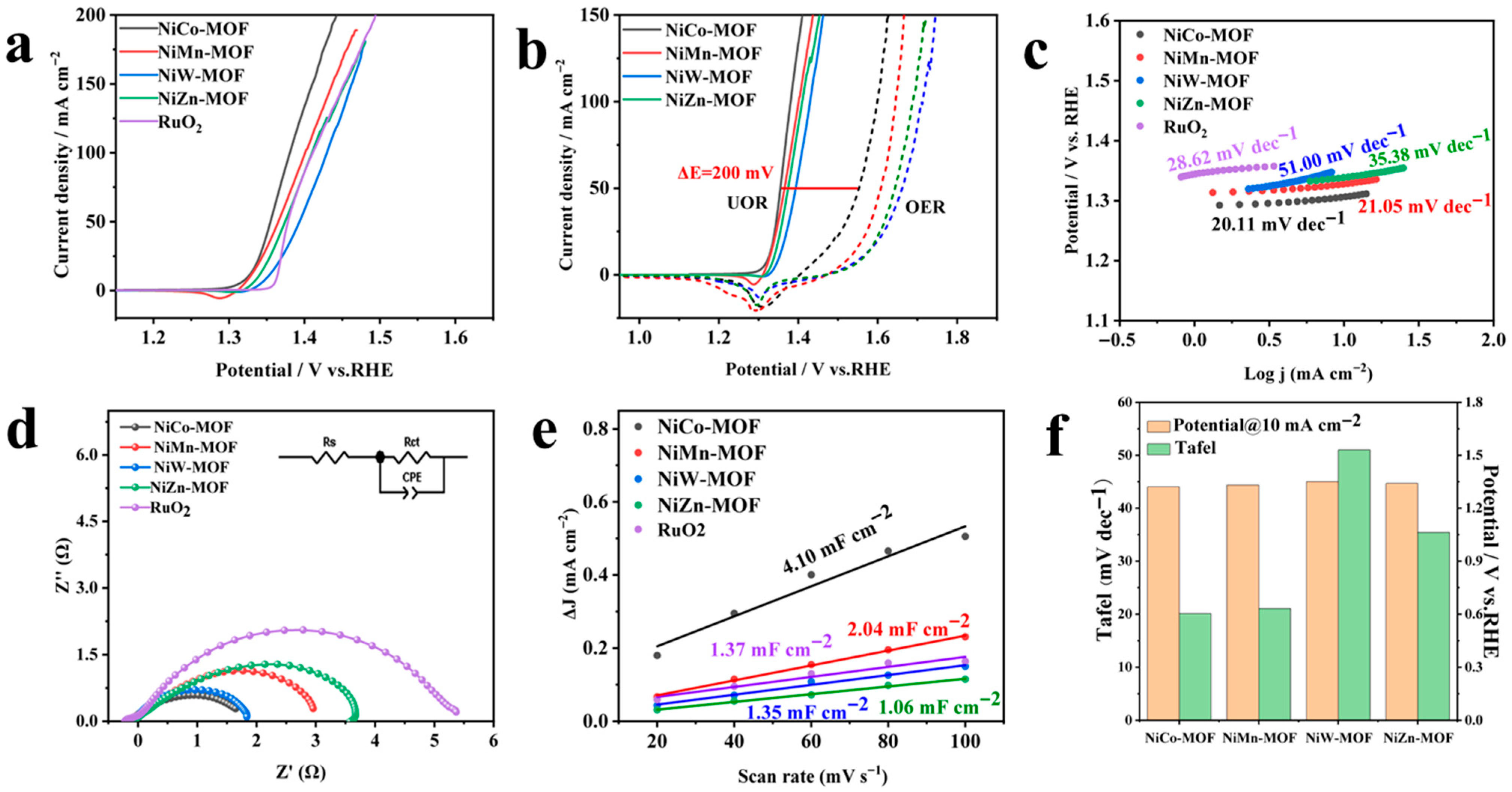
The urea oxidation reaction (UOR) performance of the catalysts was evaluated in 1 M KOH electrolyte containing 0.5 M urea. Linear sweep voltammetry (LSV) curves for UOR in 1 M KOH with 0.5 M urea (Figure 6a) demonstrate that NiCo-MOF achieves current densities of 10 and 100 mA cm−2 at potentials of 1.32 V and 1.38 V, respectively, outperforming NiMn-MOF (1.33/1.40 V), NiW-MOF (1.35/1.43 V), NiZn-MOF (1.34/1.41 V), and the precious metal benchmark RuO2 (1.36/1.41 V). Comparative LSV curves for OER and UOR (Figure 6b) reveal significant performance enhancement upon urea addition, with overpotential reductions of 200 mV, 240 mV, 270 mV, and 270 mV at 50 mA cm−2 for NiCo-MOF, NiMn-MOF, NiW-MOF, and NiZn-MOF, respectively. Tafel analysis (Figure 6c) shows NiCo-MOF possesses the smallest slope (20.11 mV dec−1), compared to NiMn-MOF (21.05 mV dec−1), NiW-MOF (51.00 mV dec−1), NiZn-MOF (35.38 mV dec−1), and RuO2 (28.62 mV dec−1), indicating lower electronic transfer resistance and more favorable reaction kinetics. The electrochemical impedance spectroscopy (EIS) can reflect the charge transfer resistance (Rct) during the electrocatalytic reaction process. Rct is the diameter of the semicircle in the high-frequency region of the electrochemical impedance spectrum, which represents the resistance of the charge transfer step at the electrode/solution interface. The smaller the diameter or radius, the smaller the resistance of charge transfer, and the lower the overpotential required under the same current density. As shown in Figure 6d of the Nyquist plot, the NiCo-MOF catalytic material has a smaller charge transfer resistance during UOR. Double-layer capacitance (Cdl) measurements (Figure 6e) were obtained from cyclic voltammetry scans at 20–100 mV s−1, revealing Cdl values of 6.75, 2.04, 1.35, 1.06, and 1.37 mF cm−2 for NiCo-MOF, NiMn-MOF, NiW-MOF, NiZn-MOF, and RuO2, respectively. The highest Cdl value (6.75 mF cm−2) of NiCo-MOF suggests greater exposure of active sites and enhanced catalytic activity. Comparative analysis of Tafel slopes and UOR potentials (Figure 6f, Table S1) demonstrates NiCo-MOF’s superior UOR activity versus recent catalysts. Stability tests (Figure S4) show excellent cycling durability, with only 0.01 V potential shift at 50 mA cm−2 after 3000 CV cycles. Comprehensive evaluation confirms UOR occurs at lower potentials than OER, with NiCo-MOF exhibiting optimal active site density, charge transfer efficiency, and reaction kinetics among all samples, demonstrating superior bifunctional catalytic activity.

3.2.2. HER Performance

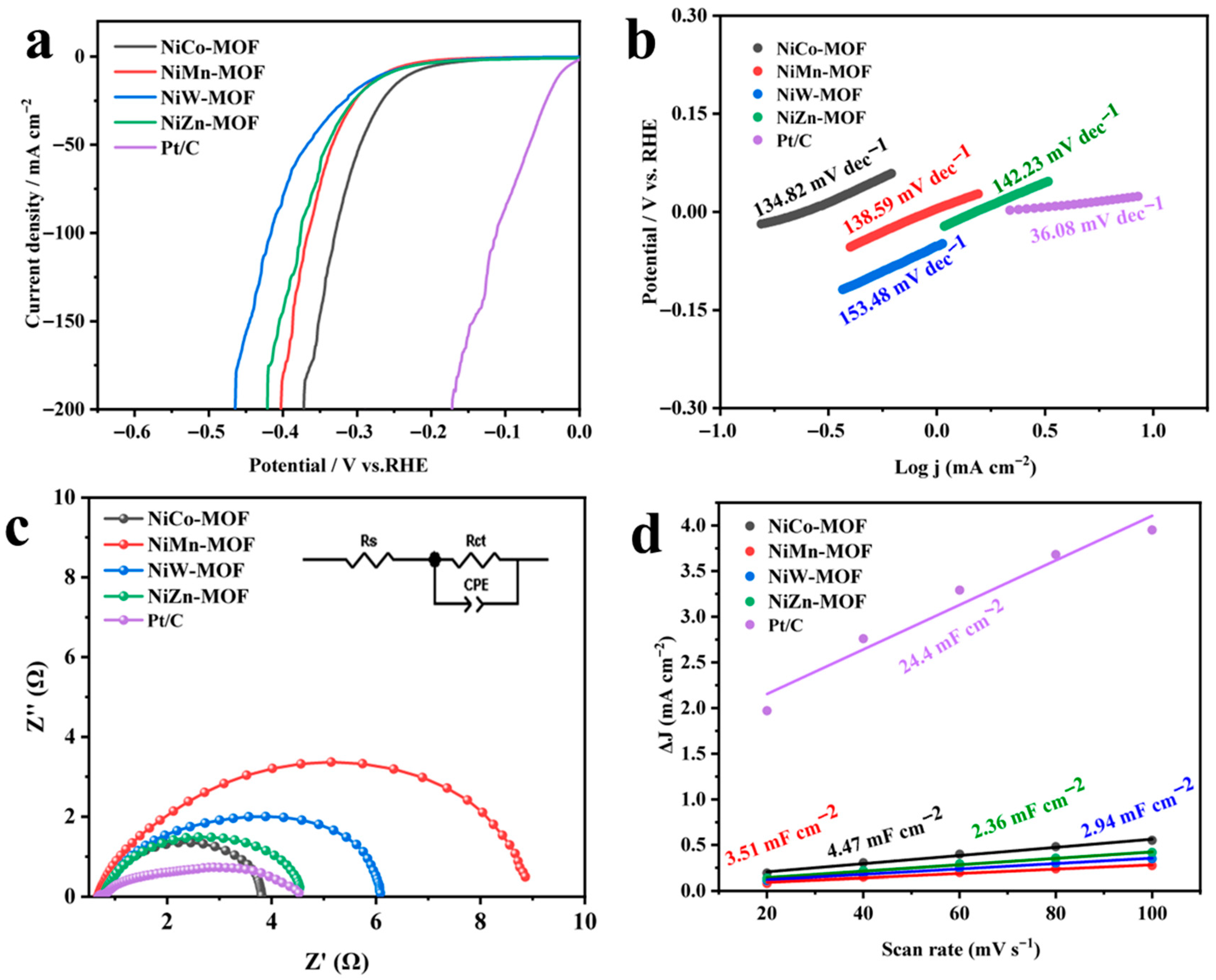
The hydrogen evolution reaction (HER) catalytic performance of NiM (M = Co, Mn, W, Zn)-MOF materials was evaluated using a three-electrode system in 1 M KOH solution with an electrochemical workstation. Linear sweep voltammetry (LSV) curves (Figure 7a) demonstrate that NiCo-MOF exhibits superior HER activity, requiring only 229 mV overpotential to achieve 10 mA cm−2 current density, second only to the precious metal benchmark Pt/C and outperforming NiMn-MOF (265 mV), NiW-MOF (265 mV), and NiZn-MOF (259 mV). Tafel analysis (Figure 7b) reveals NiCo-MOF has a relatively low slope of 117.76 mV dec−1, surpassed only by Pt/C (36.08 mV dec−1), indicating favorable reaction kinetics. Electrochemical impedance spectroscopy (Nyquist plot, Figure 7c) shows that NiCo-MOF possesses higher conductivity and lower charge transfer resistance (Rct) during HER. The double-layer capacitance (Cdl) measurements (Figure 7d) indicate NiCo-MOF has the highest value (4.47 mF cm−2), suggesting a larger electrochemically active surface area with more exposed active sites. Table S2 further compares the HER performance of the NiCo-MOF catalyst with that of the catalysts studied in recent years, from which it can be seen that the NiCo-MOF has a relatively moderate HER catalytic activity. These results collectively demonstrate that NiCo-MOF exhibits the best HER catalytic activity among the NiM (M = Co, Mn, W, Zn)-MOF series, achieving 229 mV overpotential at 10 mA cm−2 current density.

3.2.3. Performance Evaluation of NiCo(2:X)-MOF with Varied Cobalt Incorporation Levels

The aforementioned comparative study of NiM (M = Co, Mn, W, Zn)-MOF catalysts identified NiCo-MOF as the optimal candidate, demonstrating superior comprehensive performance. Building upon these findings, we systematically modulated the Co incorporation ratio in NiCo-MOF (denoted as NiCo-MOF-2:X, where X = 2, 3, 4, 5) to investigate the composition-activity relationship, as presented in Figure S5. Figure S5a–c display the LSV curves for OER, UOR, and HER of the NiCo-MOF-2:X series. The catalytic potentials for all three reactions exhibited a volcano-type dependence on the Ni:Co ratio, reaching optimal performance at 2:4 stoichiometry before declining at higher Co content (2:5). Remarkably, NiCo-MOF-2:4 achieved benchmark overpotentials of 220 mV (OER), 1.30 V (UOR), and 211 mV (HER) at 10 mA cm−2 current density. The double-layer capacitance analysis (Figure S5d) revealed a parallel trend, with Cdl values for all reactions peaking at a 2:4 ratio (>6 mF cm−2) before decreasing at 2:5 composition. These results demonstrate that catalytic enhancement correlates with increased Co incorporation up to an optimal Ni:Co ratio of 2:4, beyond which excessive Co doping induces performance degradation.

3.2.4. Urea-Assisted Overall Water Splitting

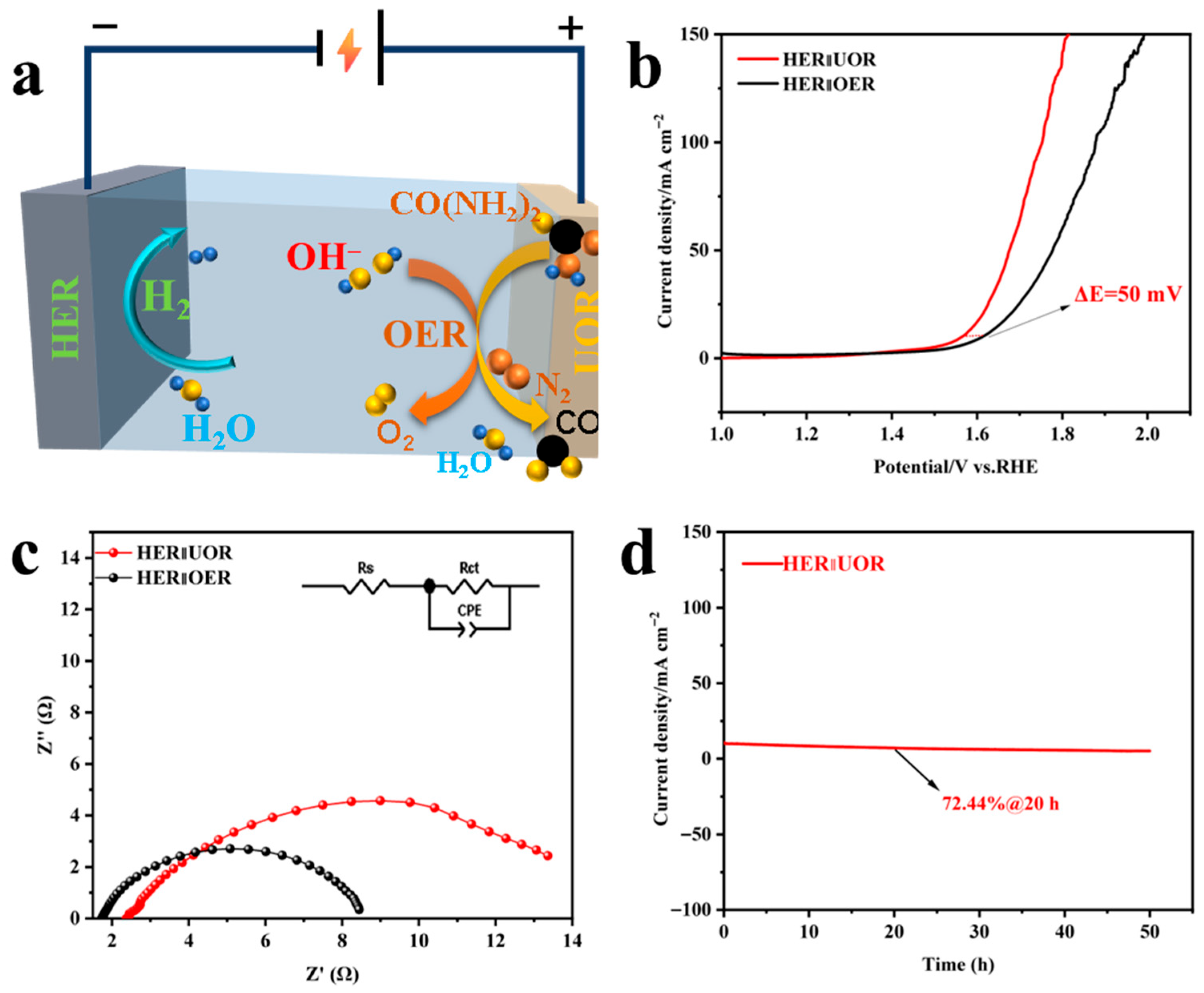
The overall water splitting performance was investigated using NiCo-MOF as both cathode and anode under conditions with and without urea assistance, as illustrated in Figure 8. Figure 8a schematically depicts the urea-assisted overall water splitting system, where the urea oxidation reaction (UOR) occurs at the anode to produce N2, CO2, and H2O, while the hydrogen evolution reaction (HER) proceeds at the cathode to generate H2. As shown in Figure 8b, the NiCo-MOF catalyst requires an applied potential of 1.61 V to achieve 10 mA cm−2 for conventional water splitting, while the potential decreases significantly to 1.56 V at the same current density when 0.5 M urea is introduced. The charge transfer kinetics were investigated using electrochemical impedance spectroscopy (EIS). As shown in Figure 8c, the impedance radius of using OER as the anode reaction was smaller than that of using UOR as the anode reaction, indicating that the influence of the charge transfer resistance size on the performance is not significant in the overall urea-assisted water splitting process. Chronoamperometric stability tests (Figure 8d) in 1 M KOH with 0.5 M urea confirm excellent durability, with the urea-assisted system maintaining stable performance at 10 mA cm−2 for 20 h.

3.3. Characterization After UOR Testing

The surface elemental composition and morphological evolution of the samples were characterized using scanning electron microscopy (SEM) and X-ray photoelectron spectroscopy (XPS). The survey XPS spectra (Figure S6a) confirm the persistent presence of Ni, Co, C, and O elements on the NiCo-MOF catalyst surface after urea oxidation reaction (UOR) testing. Most notably, the high-resolution Ni 2p spectra (Figure S6b) reveal a 0.1 eV positive shift in the Ni 2p3/2 binding energy post-UOR, while the Co 2p spectra (Figure S6c) exhibit a corresponding 0.1 eV negative shift in the Co 2p3/2 peak. This reciprocal shift demonstrates electron transfer from Ni to Co during UOR, facilitating the formation of additional NiOOH active centers and enhancing interfacial charge transfer between the electrode and electrolyte [38]. SEM images (Figure S6e,f) of NiCo-MOF before and after UOR testing show partial surface melting while maintaining the overall spherical architecture, indicating good structural stability under operational conditions.

4. Conclusions

In summary, we successfully synthesized morphologically diverse NiM (M = Co, Mn, W, Zn)-MOF catalysts via a hydrothermal method. Among them, NiCo-MOF exhibited the best performance. Further optimization of the Co incorporation ratio revealed that the NiCo-MOF catalyst with a Ni:Co molar ratio of 1:2 demonstrated the most favorable electrochemical properties. The NiCo-MOF catalyst required an overpotential of 1.45 V vs. RHE to achieve a current density of 10 mA cm−2 for the oxygen evolution reaction (OER), while only 1.33 V vs. RHE was needed for the urea oxidation reaction (UOR), indicating its superior UOR catalytic activity. When employed as both the cathode and anode for urea-assisted overall water splitting, the NiCo-MOF catalyst achieved a cell voltage of 1.56 V at 10 mA cm−2. Moreover, chronoamperometry stability tests confirmed its excellent durability, retaining 72.44% of the initial current density after 20 h of continuous operation. These results demonstrate that the NiCo-MOF catalyst is a promising bifunctional electrocatalyst for urea-assisted overall water splitting. This study also provides valuable insights for the development of novel Ni-based MOF catalysts with high electrocatalytic activity and stability.

Supplementary Materials

The following supporting information can be downloaded at https://www.mdpi.com/article/10.3390/nanoenergyadv5040017/s1. Figure S1: EDS spectrum of NiCo-MOF; Figure S2: XPS spectrum of NiM (M = Co, Mn, W, Zn)-MOF catalyst: (a) Co 2p, (b) Mn 2p, (c) W 4f, (d) Zn 2p; Figure S3: OER performance of NiM (M = Co, Mn, W, Zn)-MOF and RuO2 in 1 M KOH, (a) the LSV curves, (b) Tafel slopes in (a), (c) Nyquist plots, and (d) the Cdl curves; Figure S4: Comparison of UOR LSV curves of (a) NiCo-MOF, (b) NiMn-MOF, (c) NiW-MOF and (d) NiZn-MOF after 3000 CV cycles; Figure S5: LSV curves of (a) OER, (b) UOR, and (c) HER for NiCo-MOF 2:X (X = 2, 3, 4, 5) and (d) bar chart comparing of Cdl; Figure S6: (a) XPS spectrum, (b) Ni 2p spectrum, (c) Co 2p spectrum and (d) O 1s spectrum of the NiCo-MOF before and after the UOR process, (e) The SEM of NiCo-MOF before UOR process, (f) The SEM of NiCo-MOF after UOR process; Table S1: Comparison of other UOR catalysts; Table S2: Comparison of other HER catalysts.

Author Contributions

L.Y.: methodology, writing—original draft, writing—review and editing, data curation. Y.Y.: writing—original draft, writing—review and editing, supervision. S.L.: writing— original draft, writing—review and editing, data curation. X.X.: visualization, investigation. All authors have read and agreed to the published version of the manuscript.

Funding

The project was supported by the Scientific Research Fund of Education Department of Yunnan Province, Research and Innovation Fund for graduate students of Yunnan University (KC-24249120).

Data Availability Statement

The original contributions presented in the study are included in the article and Supplementary Materials; further inquiries can be directed to the corresponding author.

Conflicts of Interest

The authors declare no conflicts of interest.

References

  1. Xie, X.; Xu, L.; Zeng, Q.; Zhang, Z.; Xu, Z.; Yin, C.; Wang, X. A NiMOF integrated with conductive materials for efficient bifunctional electrocatalysis of urea oxidation and oxygen evolution reactions. Dalton Trans. 2024, 53, 2565–2574. [Google Scholar] [CrossRef] [PubMed]
  2. Shaddad, M.N.; Alharthi, A.I.; Aladeemy, S.A.; Arunachalam, P. Engineering oxygen vacancy on nickel-doped iron oxide nanorods as efficient bifunctional electrocatalysts for oxygen evolution and urea oxidation reaction. J. Taiwan Inst. Chem. Eng. 2024, 27, 105928. [Google Scholar] [CrossRef]
  3. Bian, H.; Wang, C.; Zhao, S.; Han, G.; Xie, G.; Qi, P.; Liu, X.; Zeng, Y.; Zhang, D.; Wang, P. Preparation of highly efficient high-entropy alloy catalysts with electrodeposition and corrosion engineering for OER electrocatalysis. Int. J. Hydrog. Energy 2024, 57, 651–659. [Google Scholar] [CrossRef]
  4. Chen, Z.; Huang, K.; Zhang, B.; Xia, J.; Wu, J.; Zhang, Z.; Huang, Y. Corrosion engineering on AlCoCrFeNi high-entropy alloys toward highly efficient electrocatalysts for the oxygen evolution of alkaline seawater. Int. J. Miner. Metall. Mater. 2023, 30, 1922–1932. [Google Scholar] [CrossRef]
  5. Zhang, H.-M.; Zhang, S.-F.; Zuo, L.-H.; Li, J.-K.; Guo, J.-X.; Wang, P.; Sun, J.-F.; Dai, L. Recent advances of high-entropy electrocatalysts for water electrolysis by electrodeposition technology: A short review. Rare Met. 2024, 1011, 178435. [Google Scholar] [CrossRef]
  6. Iqbal, W.; Hameed, A.; Tariq, I.; Shah, S.S.A.; Nadeem, M.A. Cobalt hydroxide supported nickel nanoparticles for an efficient electrocatalytic urea oxidation reaction. Electrochim. Acta 2023, 467, 143055. [Google Scholar] [CrossRef]
  7. Nourshargh, B.; Ghaffarinejad, A.; Barati Darband, G. Water splitting by CoFeLDH@NiFeS nanoelectrocatalyst assisted urea electrooxidation reaction. J. Environ. Chem. Eng. 2023, 12, 111629. [Google Scholar] [CrossRef]
  8. Yu, H.; Xu, W.; Chang, H.; Xu, G.; Li, L.; Zang, J.; Huang, R.; Zhu, L.; Yu, B. Electrocatalytic Ni-Co Metal Organic Framework for Efficient Urea Oxidation Reaction. Processes 2023, 11, 3035. [Google Scholar] [CrossRef]
  9. Sreekanth, T.V.M.; Naresh, B.; Prasad, K.; Kim, J.; Yoo, K. NiO/ATO as an efficient bifunctional electrocatalysts for oxygen evolution and urea oxidation reactions. Inorg. Chem. Commun. 2024, 170, 113315. [Google Scholar] [CrossRef]
  10. Guo, F.; Cheng, D.; Chen, Q.; Liu, H.; Wu, Z.; Han, N.; Ni, B.-J.; Chen, Z. Amorphous electrocatalysts for urea oxidation reaction. Prog. Nat. Sci. Mater. Int. 2024, 34, 362–375. [Google Scholar] [CrossRef]
  11. Cao, X.; Wang, T.; Qin, H.; Lin, G.; Zhao, L.; Jiao, L. Crystalline—Amorphous interfaces of NiO-CrOx electrocatalysts for boosting the urea oxidation reaction. Nano Res. 2022, 16, 3665–3671. [Google Scholar] [CrossRef]
  12. Diao, Y.; Liu, Y.; Hu, G.; Zhao, Y.; Qian, Y.; Wang, H.; Shi, Y.; Li, Z. NiFe nanosheets as urea oxidation reaction electrocatalysts for urea removal and energy-saving hydrogen production. Biosens. Bioelectron. 2022, 211, 114380. [Google Scholar] [CrossRef]
  13. Rodrigues, E.M.; Fernandes, C.M.; Alves, O.C.; Santos, E.C.S.; Garcia, F.; Xing, Y.; Ponzio, E.A.; Silva, J.C.M. MagnetoElectroCatalysis: A new approach for urea electro-oxidation reaction on nickel-iron oxide catalyst. Int. J. Hydrog. Energy 2023, 51, 1460–1470. [Google Scholar] [CrossRef]
  14. Song, S.; Huang, X.; Yang, Y.; Feng, L. Se self-doped Ni(OH)2 for an efficient urea oxidation reaction. Chem. Commun. 2024, 60, 10906–10909. [Google Scholar] [CrossRef]
  15. He, J. Role of Zr in promoted activity of urea oxidation reaction and oxygen evolution reaction for NiFe layered double hydroxide. Int. J. Hydrog. Energy 2024, 57, 929–938. [Google Scholar] [CrossRef]
  16. Liu, H.; Luo, J.; Zhu, S.; Cui, Z.; Liang, Y.; Yu, S.; Wei, J. Endowing nickel nitride with moderate amount of Ni0 species for the enhanced urea oxidation reaction reactivity. J. Electroanal. Chem. 2023, 948, 117821. [Google Scholar] [CrossRef]
  17. Li, J.; Hu, F.; Hei, J.; Liu, G.; Wei, H.; Wang, N.; Wei, H. Hierarchical Ni–Mo–P nanoarrays toward efficient urea oxidation reaction. Dalton Trans. 2022, 51, 18059–18067. [Google Scholar] [CrossRef]
  18. Liu, J.; Du, Y.; Zheng, D.; Wang, S.; Hou, Y.; Zhang, J.; Lu, X.F. Nickel-Based Anode Electrocatalysts for Hydrogen Production. ACS Mater. Lett. 2023, 6, 466–481. [Google Scholar] [CrossRef]
  19. Boggs, B.K.; King, R.L.; Botte, G.G. Urea electrolysis: Direct hydrogen production from urine. Chem. Commun. 2009, 32, 4859–4861. [Google Scholar] [CrossRef] [PubMed]
  20. Asiain-Mira, R.; Smith, C.; Zamora, P.; Monsalvo, V.M.; Torrente-Murciano, L. Hydrogen production from urea in human urine using segregated systems. Water Res. 2022, 222, 118931. [Google Scholar] [CrossRef]
  21. Kun, X.; Linjian, Y.; Yang, X.; Haidong, Z.; Jia, C.; Yuan, G. Cerium-incorporated Ni2P nanosheets for enhancing hydrogen production from overall water splitting and urea electrolysis. J. Alloys Compd. 2022, 912, 165234. [Google Scholar] [CrossRef]
  22. Zheng, J. Pt-free NiCo electrocatalysts for oxygen evolution by seawater splitting. Electrochim. Acta 2017, 247, 381–391. [Google Scholar] [CrossRef]
  23. Zemtsova, V.M.; Oshchepkov, A.G.; Savinova, E.R. Unveiling the Role of Iron in the Nickel-Catalyzed Urea Oxidation Reaction. ACS Catal. 2023, 13, 13466–13473. [Google Scholar] [CrossRef]
  24. Wu, C.; Wang, X.; Huang, M.; Meng, C.; Chang, L.; Xu, D.; Pei, W. Design and fabrication of intermetallic NiCo electrocatalysts for alkaline HER. Nanoscale 2024, 16, 15148. [Google Scholar] [CrossRef]
  25. Zhang, Y.; Guo, Z.; Fang, Y.; Tang, C.; Meng, F.; Miao, N.; Sa, B.; Zhou, J.; Sun, Z. Rational design of bimetallic MBene for efficient electrocatalytic nitrogen reduction. J. Colloid Interface Sci. 2024, 670, 687–697. [Google Scholar] [CrossRef]
  26. Cheng, W.; Wang, H.; Gu, Z.; Cao, M.; He, C.; Li, J.; Li, Z.; Tian, L. Modulation of the electronic structure of CoP by surface and interface codoping boosts electrocatalytic oxygen evolution reaction. Int. J. Hydrog. Energy 2023, 51, 914–921. [Google Scholar] [CrossRef]
  27. Yin, X.; Zhu, K.; Ye, K.; Yan, J.; Cao, D.; Zhang, D.; Yao, J.; Wang, G. FeNi supported on carbon sponge for efficient urea oxidation in direct urea fuel cell. J. Colloid Interface Sci. 2023, 654, 36–45. [Google Scholar] [CrossRef]
  28. Yuan, Y.; Wang, K.; Zhong, B.; Yu, D.; Ye, F.; Liu, J.; Dutta, J.; Zhang, P. MOF-Derived Iron-Cobalt Phosphide Nanoframe as Bifunctional Electrocatalysts for Overall Water Splitting. Energy Environ. Mater. 2024, 7, 12747. [Google Scholar] [CrossRef]
  29. Kayode Adesina, A.; Nobanathi Wendy, M. Porous metal−organic framework (MOF)-based and MOF-derived electrocatalytic materials for energy conversion. Mater. Today Energy 2021, 21, 100816. [Google Scholar] [CrossRef]
  30. Wang, K.; Kang, J.; Jin, L.; Yang, L.; Liu, Y.; Li, Y.; Chen, G.; Xu, H. Defect engineering of MOF toward enhanced electrocatalytic water oxidation. Ionics 2023, 29, 5397–5403. [Google Scholar] [CrossRef]
  31. Marquez-Montes, R.A.; Kawashima, K.; Son, Y.J.; Weeks, J.A.; Sun, H.H.; Celio, H.; Ramos-Sánchez, V.H.; Mullins, C.B. Mass transport-enhanced electrodeposition of Ni–S–P–O films on nickel foam for electrochemical water splitting. J. Mater. Chem. A 2021, 9, 7736–7749. [Google Scholar] [CrossRef]
  32. Yan, X.; Hu, Q.-T.; Wang, G.; Zhang, W.-D.; Liu, J.; Li, T.; Gu, Z.-G. NiCo layered double hydroxide/hydroxide nanosheet heterostructures for highly efficient electro-oxidation of urea. Int. J. Hydrog. Energy 2020, 45, 19206–19213. [Google Scholar] [CrossRef]
  33. Kuang, M.; Han, P.; Huang, L.; Cao, N.; Qian, L.; Zheng, G. Electronic Tuning of Co, Ni-Based Nanostructured (Hydr)oxides for Aqueous Electrocatalysis. Adv. Funct. Mater. 2018, 28, 1804886. [Google Scholar] [CrossRef]
  34. Khalafallah, D.; Ouyang, C.; Zhi, M.; Hong, Z. Heterostructured Nickel-Cobalt Selenide Immobilized onto Porous Carbon Frameworks as an Advanced Anode Material for Urea Electrocatalysis. ChemElectroChem 2019, 6, 5191–5202. [Google Scholar] [CrossRef]
  35. Wang, Y.; He, W.; Du, X.; Zhang, X. Electrocatalytic urea oxidation based on M (M = Fe, Cr, Mo)-Ni3S2/Co3S4: Performance optimization and mechanism analysis. Fuel 2024, 376, 132749. [Google Scholar] [CrossRef]
  36. Lu, X.; Wang, T.; Cao, M.; Cheng, W.; Yang, H.; Xu, H.; He, C.; Tian, L.; Li, Z. Homogeneous NiMoO4–Co(OH)2 bifunctional heterostructures for electrocatalytic oxygen evolution and urea oxidation reaction. Int. J. Hydrog. Energy 2023, 48, 34740–34749. [Google Scholar] [CrossRef]
  37. Shukla, R.K.; Chaturvedi, A.K.; Volla, C.M.R. Catalytic Cascade Cyclization and Regioselective Hydroheteroarylation of Unactivated Alkenes. ACS Catal. 2021, 11, 7750–7761. [Google Scholar] [CrossRef]
  38. Zhao, X.; Che, M.; Gong, Y. Synthesis and performance study of Fe2WO6@Ni3S2-WS2/NF for efficient electrolytic water to hydrogen. Sustain. Mater. Technol. 2025, 43, e01302. [Google Scholar] [CrossRef]
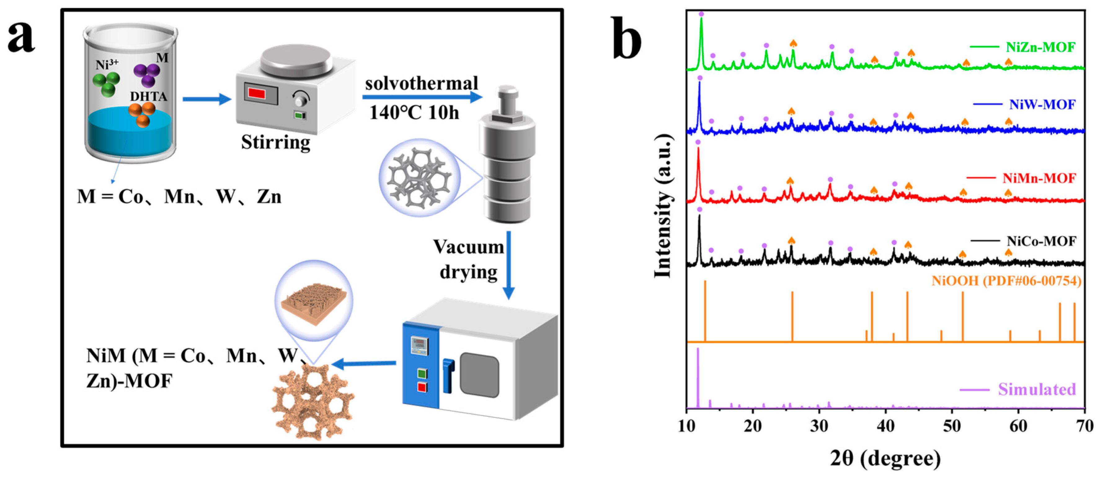
Figure 1. (a) Schematic diagram of the preparation process of NiM (M = Co, Mn, W, Zn)-MOF, (b) XRD of NiM (M = Co, Mn, W, Zn).
Nanoenergyadv 05 00017 g001
Figure 2. SEM of NiMn-MOF (a,e), NiW-MOF (b,f), NiZn-MOF (c,g) and NiCo-MOF (d,h).
Nanoenergyadv 05 00017 g002
Figure 3. (a,b) TEM of NiCo-MOF, (c) Elemental mapping images of NiCo-MOF.
Nanoenergyadv 05 00017 g003
Figure 4. XPS spectrum of NiM (M = Co, Mn, W, Zn)-MOF catalyst: (a) Full spectrum, (b) Ni 2p, (c) C 1s, and (d) O 1s.
Nanoenergyadv 05 00017 g004
Figure 5. N2 adsorption and desorption isotherm curve of (a) NiMn-MOF catalyst, (b) NiW-MOF catalyst, (c) NiZn-MOF catalyst, and (d) NiCo-MOF catalyst.
Nanoenergyadv 05 00017 g005
Figure 6. UOR performance of NiM (M = Co, Mn, W, Zn)-MOF and RuO2 in 1 M KOH + 0.5 M urea. (a) The LSV curves; (b) The LSV curves of NiM (M = Co, Mn, W, Zn)-MOF for UOR and OER; (c) Tafel slopes in (a); (d) Nyquist plots; (e) The Cdl curves, and (f) performance comparison of NiM (M = Co, Mn, W, Zn)-MOF.
Nanoenergyadv 05 00017 g006
Figure 7. HER performance of NiM (M = Co, Mn, W, Zn)-MOF and Pt/C in 1 M KOH. (a) The LSV curves; (b) Tafel slopes in (a); (c) Nyquist plots; and (d) the Cdl curves.
Nanoenergyadv 05 00017 g007
Figure 8. Overall water splitting performance of NiCo-MOF. (a) Schematic diagram, (b) LSV, (c) EIS, and (d) stability testing of overall water breakdown in 1 M KOH + 0.5 M urea.
Nanoenergyadv 05 00017 g008
Disclaimer/Publisher’s Note: The statements, opinions and data contained in all publications are solely those of the individual author(s) and contributor(s) and not of MDPI and/or the editor(s). MDPI and/or the editor(s) disclaim responsibility for any injury to people or property resulting from any ideas, methods, instructions or products referred to in the content.