Article

Metal-Free, Bio-Triboelectric Nanogenerator Based on a Single Electrode of Bacterial Cellulose Modified with Carbon Black

by
Andre L. Freire
1,
Lais R. Lima
2,
Iuri C. M. Candido
1,
Luygui G. Silva
3,
Sidney J. L. Ribeiro
3,
Emanuel Carrilho
2,
Thais L. Oliveira
4,
Luiz Fernando C. de Oliveira
4,
Hernane S. Barud
5 and
Helinando P. de Oliveira
1,*
1
Institute of Materials Science, Universidade Federal do Vale do São Francisco—UNIVASF, Juazeiro 48902-300, BA, Brazil
2
Instituto de Química de São Carlos, Universidade de São Paulo—USP, São Carlos 13566-590, SP, Brazil
3
Institute of Chemistry, São Paulo State University—UNESP, Araraquara 14800-060, SP, Brazil
4
Núcleo de Espectroscopia e Estrutura Molecular (NEEM), Departament of Chemistry, Universidade Federal de Juiz de Fora—UFJF, Juiz de Fora 36036-900, MG, Brazil
5
Biopolymers and Biomaterials Laboratory (BioPolMat), Universidade de Araraquara—UNIARA, Araraquara 14801-320, SP, Brazil
*
Author to whom correspondence should be addressed.
Nanoenergy Adv. 2024, 4(1), 110-121; https://doi.org/10.3390/nanoenergyadv4010006
Submission received: 19 December 2023 / Revised: 27 January 2024 / Accepted: 1 February 2024 / Published: 7 February 2024

Abstract

:
Developing metal-free electrodes for prototypes of bio-based devices is an essential step in producing non-toxic components for implantable devices and wearables. In particular, the advancement in self-powered devices is a hot topic for several applications due to the possibility of creating free-battery devices and sensors. In this paper, the modification of bacterial cellulose by the progressive incorporation of carbon black (a conductive filler) was explored as a prototype for bio-based electrodes for triboelectric nanogenerators. This process was controlled by the percolation pathways’ activation through the contact of carbon black grains with the bacterial cellulose membrane, which represents a critical step in the overall process of optimization in the power output performance, reaching an open circuit voltage value of 102.3 V, short circuit current of 2 μA, and power density of 4.89 μW/cm2.

1. Introduction

Advances in the Internet of Things and wearables have been highly favored by the initiative of producing flexible electronics and self-powered devices that harvest energy from mechanical movement/environment to convert it into electrical energy [1,2]. When considering the use of these devices as implantable or components [3,4] that operate in contact with the skin, the requisites of non-toxicity and biocompatibility are critical [5], making relevant the development of bio-based triboelectric nanogenerators (TENGs) [6,7,8] with several applications in water-harvesting systems [9], sweat sensors [10], and sensors for tactile perception [11].
Cellulose-based supports have been considered promising templates for active components in triboelectric nanogenerators [12,13]. The high biocompatibility and biodegradability [14,15] of these polysaccharides and their abundance in nature can be considered promising eco-friendly factors that make implementing cellulose-based devices possible. In particular, bacterial cellulose (BC) is a kind of cellulose synthesized by microorganisms that introduces the advantages of the high purity of the cellulose, avoiding additional steps for removing lignin and hemicellulose [5,15,16,17]. A standard application for BC-based triboelectric nanogenerators is based on its use as a friction layer [1,18] due to the possibility of tuning in the charge density of the membrane. Strategies applied in the control of the porous degree and the dielectric constant of the friction layers have been explored by doping bacterial cellulose with BaTiO3 [19], nitrogen-based and methyl groups [20], and zinc oxide derivatives [3].
Despite these strategies to control the output performance by tuning the dielectric properties/ surface characteristics of the frictional layers, the development of free-of-metal electrodes represents another critical step toward the development of all-eco-friendly bio-TENGs since the typical procedure for the production of electrodes for TENGs is based on the deposition of metal layers on the friction-back face. The related issues of mechanical resistance, wearability, and costs are drawbacks of metal-based components [21].
In this paper, carbon black as a conductive filler is incorporated into BC films as a part of a strategy to produce modified BC-based films for metal-free electrodes. With the progressive incorporation of the conductive filler in the membrane, a carbon black concentration-dependent profile is expected to be observed in the electrical response of the TENG. Above a critical filler concentration, the conductive grains must create pathways along with the material, providing an adequate charge transfer. This process can be observed not only in the electrical response of the electrodes but also in the overall performance of the assembled TENG.

2. Materials and Methods

2.1. Materials

Carbon black was purchased from CABOT, São Paulo, SP, Brazil, while HB Biotech, Araraquara, SP, Brazil, kindly provided bacterial cellulose membranes. Silicone rubber Ecoflex™ 00-30 (Smooth-On Inc., Macungie, PA, USA) was used as a tribonegative layer and was prepared through the mixing of equal parts of A (10 g) and B (10 g) of the Ecoflex 00-30 elastomer for 20 min until a homogeneous dispersion of the material was observed. A controlled roughness surface was created by using a mold of sandpaper foil (100 × 30 mm2) over which the resulting solution of Ecoflex was poured and cured at 25 °C for 24 h.
To prepare BC/carbon black films, moist BC membranes were cut into squares with an area of 25 cm2 and then immersed into 40 mL of the aqueous dispersion of carbon black in a 250 mL Erlenmeyer glass. In an orbital shaker, the solution was kept under constant stirring (120 rpm) for 24 h at room temperature (25 °C). The impregnation with an increasing amount of the filler (carbon black) was conducted according to [22], with the specific amounts of 1 mg, 3 mg, 6 mg, 9 mg, and 12 mg resulting from the dry mass of the BC in the samples BC-1 wt%, BC-3 wt%, BC-6 wt%, BC-9 wt%, and BC-12 wt%, respectively. The dried BC membranes impregnated with carbon black were then cut into 4 cm × 4 cm squares in triplicate for each concentration.
The TENG was assembled according to a single-electrode configuration in which a polylactic acid (PLA) layer was used as the tribopositive layer, the Ecoflex was used as the tribonegative component, and a modified bacterial cellulose as the electrode. The complete scheme for the assembled TENG is shown in Figure 1, in which a 3D-printed layer of PLA with 16 cm2 is connected to the arm of a reciprocating linear motor that operates in the range of 1 Hz–7 Hz, providing contact–separation for the friction layers of PLA and Ecoflex deposited on a BC membrane prepared with different contents of the carbon black (from 1 wt% to 12 wt%). The general mechanism of contact electrification was established from the first contact of the tribopairs, inducing a layer of positive charges of PLA and negative ones on the Ecoflex membrane. As observed in the scheme of Figure 1, no electrode was connected to the tribopositive layer, while the unique electrode was applied on the back of the tribonegative layer (Ecoflex).
In the initial configuration (before the contact of the tribopairs), there is no electric output nor accumulated charge at the interfaces. Once the PLA comes into contact with the Ecoflex layer, electrons are transferred to the Ecoflex surface, while the positive charge migrates to the PLA surface. With the release of the force applied on the TENG, the tribopairs tend to separate, increasing the potential difference and driving a flow of electrons in the direction of the ground along with the resistance load. The current tends to zero after the complete release of the force and returns in the opposite direction under compressive forces that approach the tribolayers, generating an alternate current in the output component.

2.2. Characterization

The thermal properties of the bacterial cellulose membranes were determined by thermogravimetric analysis (TGA) with curves acquired using a TA Instruments (New Castle, DE, USA) SDT Q600 in an atmosphere of O2 flowing at 100 mL min−1 and at a heating rate of 10 °C min−1 over a range of 30–850 °C, with 5 mg of the samples and an alumina pan as the reference. The vibrational spectroscopy technique in the infrared region was used to structurally characterize the BC membranes in the attenuated total reflectance (FTIR-ATR) mode (diamond crystal). The spectra were acquired in a Bruker spectrometer (VERTEX 70) in the transmission module at a resolution of 2 cm−1 and the range of 4000–400 cm−1. The morphology of the pure and modified bacterial cellulose by the impregnation of carbon black was evaluated by scanning electron microscopy (Vega 3XM Tescan, Brno – Kohoutovice, Czech Republic). For the evaluation of the electrical performance of the TENG, the open-circuit voltage was determined by a digital oscilloscope (MSO1104Z, Rigol, Portland, OR, USA) using a 100 MΩ probe LF-250S (Minipa, São Paulo, SP, Brazil). For short-circuit current determination, the oscilloscope was connected to a circuit with an LMC6001 current preamplifier, following the steps reported in Ref. [23].
The mechanical properties of the bacterial cellulose and the modified bacterial cellulose were analyzed using an electromechanical universal machine (EMIC model DL 10000) with the data processed using the TESC software. The Raman spectra of the carbon black samples and the BC_cb films (1, 3, 6, 9, and 12 wt%) were obtained using a dispersive Raman equipment of the Bruker model Senterra with an excitation line at 532 nm, an average of 10 scans and 5 s of time acquisition, a laser power of 2 mW at the sample, and a spectral resolution of 3 cm−1. The BC film sample was analyzed using an interferometric Raman instrument from Bruker model RFS-100, with an excitation line at 1064 nm of a Ne/YAG solid-state laser, using 100 mW of laser power at the sample surface, an average of 512 scans, and 4 cm−1 of resolution. All spectra were obtained at least twice to avoid any thermal decomposition/chemical degradation at the sample surface, comparing the intensity and position of each main band on the spectra.

3. Results

3.1. Thermal and Structural Characterization of CB and CB-Modified Membranes

The thermal behavior of the BC/carbon black films was evaluated and the results are shown in Figure S1. As it can be seen, comparing the pristine BC and pristine carbon black, three weight loss events were observed for BC, namely: (1) from room temperature to ca. 150 °C, indicating that there was dehydration below 100 °C; (2) from ca. 150 to 465 °C, associated with the main thermal degradation of BC (~350 °C), as the depolymerization and decomposition of glucosyl units; and (3) above 465 °C, assigned to the carbonization of the degradation products, resulting in no residues [24]. On the other hand, the pristine carbon black presented a main weight loss event, referring to the degradation of the material between 600 °C and 720 °C [25]. The residue observed at 850 °C was approximately 4%. The main thermal event for the carbon-black-containing films was observed at similar temperatures (ca. 350 °C), due mostly to the decomposition of the BC molecules. The addition of carbon black particles showed a slight increase in Tonset and Toffset for all the composites (ca. 312–320 °C and 525 °C, respectively) compared to the pristine BC (ca. 300 °C and 480 °C, respectively); see Figure S2. For the carbon-black-containing samples, the residue at 850 °C can be associated with the ash from the carbon black added to the BC matrix. The significant increase in the residue was limited to 3%, even for the samples containing more than this concentration of carbon black. The slight increase in the Tonset and Toffset of the functionalized films suggests good interactions between the BC membranes and their particle counterparts.
A structural characterization was performed by FTIR and Raman spectroscopy. Figure S1b shows the FTIR spectra of the pristine BC and BC with varying concentrations of carbon black (1, 3, 6, 9, and 12 wt%). All samples present uniform spectral profiles, indicating similar absorption band patterns. The observed uniformity in response suggests that the introduction of carbon black (cb) minimally affects the chemical structure of cellulose. The observed infrared spectra indicate the characteristic group frequencies for BC: the band at approximately 3340 cm−1 corresponds to intra- and inter-O–H stretching in cellulose I; the weak band at around 2900 cm−1 is associated with the C–H stretching of CH2 and CH3 groups or CH2 asymmetric stretching; that at 1640 cm−1 corresponds to the H–O–H bending of absorbed water; that at 1425 cm−1 is attributed to CH2 symmetric bending or O–H in-plane bending; that at 1320 cm−1 corresponds to C–H deformation, O–H in-plane bending, and the out-of-plane wagging of CH2 groups; the absorption band at 1160 cm−1 suggests the presence of the C–O–C antisymmetric bridge stretching of 1,4-β-D-glucoside in BC; the bands at 1000–1110 cm−1 are hypothesized to be related to C–O stretching vibration in primary alcohol and C–O–C skeletal vibration; and the bands at 400–1000 cm−1, particularly around 900 cm−1, correspond to the antisymmetric out-of-phase ring stretching of β-glucosidic linkages, indicating the presence of cellulose II [26,27,28,29,30].
Figure S3 shows the Raman spectra for each one of the investigated samples. The bands at 1344 and 1578 cm1 refer to the D (disorder band) and G (graphite band) bands of carbon [31,32]; it is important to notice that the relationship between the overall intensities on the Raman spectra are not the same, strongly suggesting a significant heterogeneity on the obtained samples. Table 1 shows some of the characteristic bands of cellulose, with the most intense modes at 2980 cm1, characteristic of the C–H stretching vibration, and at 1380 cm1 attributed to the C–O–H vibration; in the range of 1000–1300 cm1, the intense bands at 1122 and 1097 cm1 are included, assigned to the C–C stretching and C–O–H and C–C–H deformation modes, respectively. The Raman spectroscopy analysis of the BC_cb samples with different percentages, 1%, 3%, 6%, 9%, and 12%, was carried out at three different points of each of these samples. The laser was focused on darker, lighter, and intermediate points. It was observed that, in the five samples, the spectra differed according to the analyzed point. When focusing on the darker points, the carbon black bands D and G were straightforward but with different intensity ratios (ID/IG). When analyzing the intermediate and lighter points, in addition to the D and G bands being less intense, it was observed that the bands referring to the BC film appeared to have a greater or lesser predominance. In the lighter points, they were more evident, and in the darker points, they were less evident. Furthermore, the variability in the intensity ratio of the G and D bands, both in the carbon black and for the films with different CB concentrations, showed that there was a lesser or greater interaction between the carbon black and the matrix (bacterial cellulose film) and how it reflected the heterogeneity of the material [33,34,35]. All intensity relationships are shown in Table S1 in the Supplementary Materials.

3.2. Morphology Evaluation

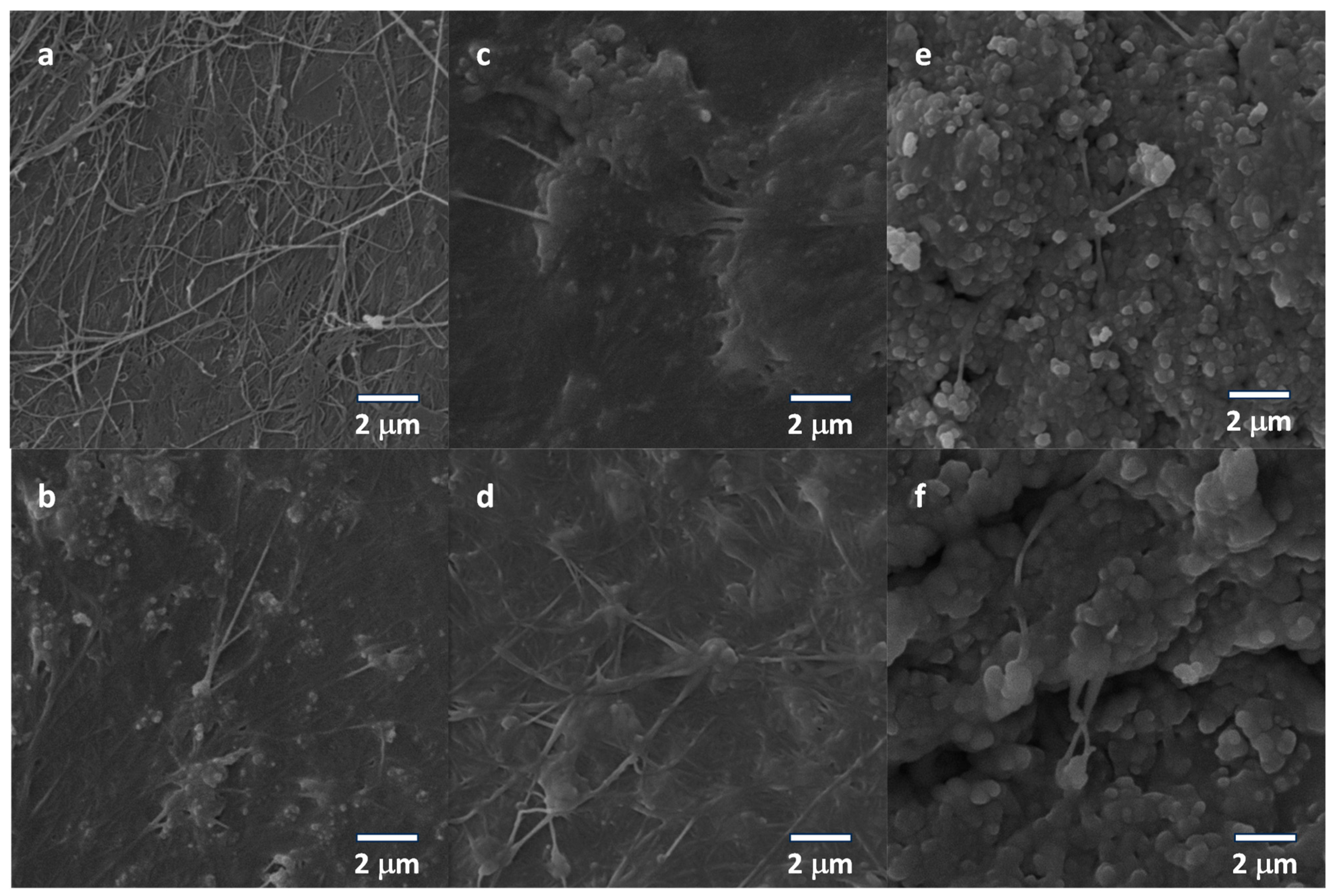
The morphology of the bacterial cellulose (pure and modified) membranes was evaluated using scanning electron microscopy, in which the surface of the membranes was analyzed as a function of the concentration of the conductive filler. As seen in Figure 2a, for the samples prepared without the conductive filler (negative control), it is possible to identify a network of structures composed of long nanofibers with typical morphology, as reported in the literature [36,37,38].
At increasing concentrations of the filler, it can be observed, for samples BC-1 wt%—Figure 2b, BC-3 wt%—Figure 2c, BC-6 wt%—Figure 2d, BC-9 wt%—Figure 2e, and BC-12 wt%—Figure 2f, that an increase in the density of grains (and aggregates) is established between the fibers and superposed on those structures, a critical condition that affects the morphology and mechanical and electrical properties of the modified cellulose-based support.

3.3. Electrical Characterization of the Electrodes

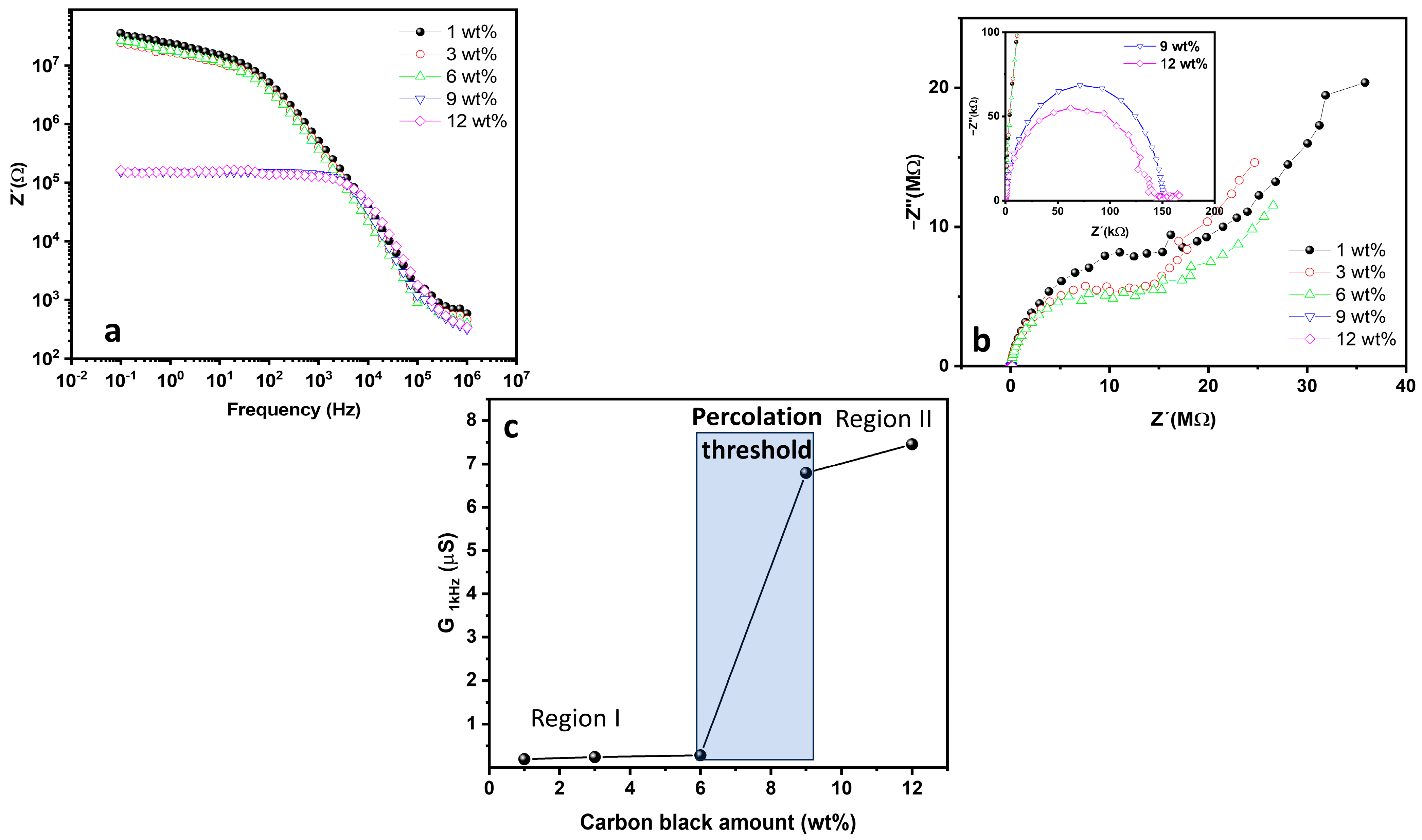
It is worth mentioning that a significant modification in the electrical response of the bacterial cellulose for use as electrodes is required since a high conductivity of the current collectors is desirable for corresponding applications and an intrinsic poor electrical conductivity is observed in the pristine bacterial cellulose. The electrical characterization of the bacterial cellulose electrodes with different concentrations of the conductive fillers was evaluated by the electrical impedance spectroscopy of the electrodes (across the transversal direction) in the range of frequency from 0.1 Hz to 1 MHz (see Figure 3a)—allowing for the process of transport and polarization to be conveniently addressed. As expected, at the limit of low concentration of carbon black in the membranes, the high values for the real part of the impedance at a low frequency confirm that the low density of the conductive fillers is not sufficient to create current pathways along the sample—with direct consequences on the electrical response of the material. With the increase in the concentrations of carbon black, a strong decrease in the low-frequency impedance level of the membranes (from 107 Ω to 105 Ω) confirms that the contact with conductive grains favors the reduction in the overall electrical resistance. These results are also observed in the Nyquist plot (see Figure 3b), in which it can be confirmed that the characteristic semicircle for the samples is progressively reduced with the increase in the additive concentrations. The inset confirms that lower values for the characteristic diameter in a semicircle are obtained with the increase in concentrations of the conductive filler. As a standard evaluation of the percolation-type process, the calculation of the conductance level (G) versus the amount of additive is provided from the plot of the real part of the admittance at 1 kHz (low-frequency region in which the real part of the impedance is constant) versus the concentration of carbon black, expressed by G = Z Z 2 + Z 2 .
As reported in the literature [39], the behavior of the conductance (G) versus the content of conductive filler in composites is expressed by a first process (a non-ohmic response at region I in Figure 3c) due to the barrier-tunneling effect in the gap between the carbon black aggregates and the bacterial cellulose structure. At ohmic conditions (region II in Figure 3c), the linked particles of the conductive filler form a network that favors the total current along the structure—with the transition between the non-ohmic and ohmic region determined by the percolation threshold in which the conductance of the composite jumps up 10× as a consequence of the formation of an electron pathway in the bacterial cellulose composite.
The influence of the conductive filler on the overall response of the modified BC membrane was also evaluated using standard mechanical assays, in which the stress–strain response of the samples was tested with the progressive incorporation of the carbon black, with the results being shown in Figure S4. As can be seen, the progressive incorporation of the conductive filler minimally affects the maximum value for the tensile strength at the condition of the ultimate strength (negligible variations relative to the value of samples prepared with different content amounts of carbon black). On the other hand, differences are observed for the absorbed energy—an indication of a noticeable change in the rate of elongation that shifts from a maximum strain of 9 wt% for the pure BC to values in the range of 12–27% for the doped membranes as a consequence of the incorporation of carbon black, with a maximum elongation for the sample with 9 wt%.

3.4. TENG Evaluation Performance

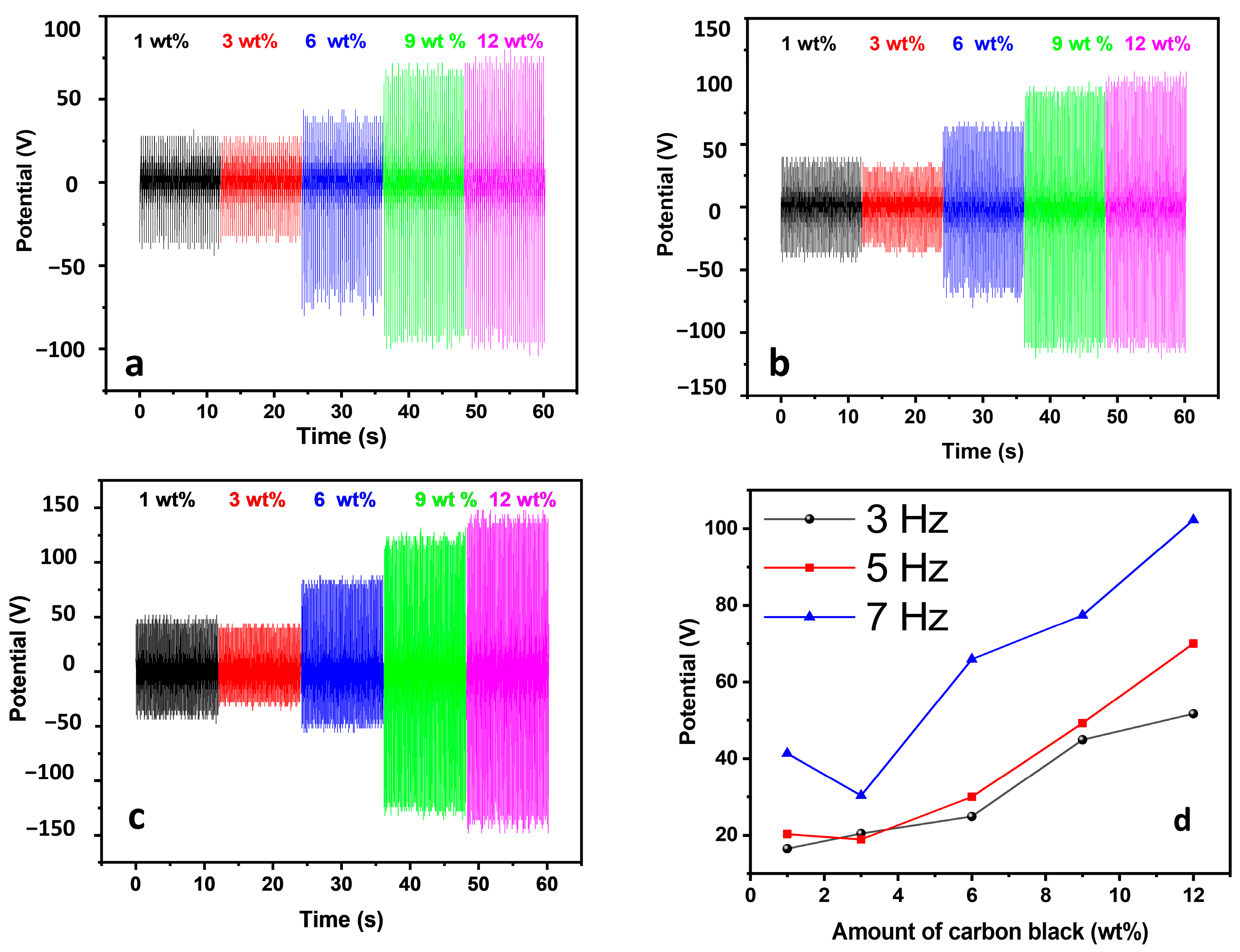
The influence of the electrical properties of the modified electrodes on the overall electrical output performance of the TENGs can be observed in the electrical generation (voltage and current) output of the assembled TENGs at different frequencies of operation and with the increase in the concentrations of the conductive filler. According to Figure 4a, it is possible to observe that a low open-circuit voltage is observed (20 V) for the samples prepared with a lower concentration of carbon black (C < 3 wt%) with a maximum voltage value of 90 V for the samples prepared with 12 wt% of the additive. Similarly, this behavior is observed for samples excited at increasing frequencies of operation (3 Hz—Figure 4a, 5 Hz—Figure 4b, and 7 Hz—Figure 4c) with higher values of the voltage output obtained at a higher frequency of operation due to the increase in the energy transfer rate from the mechanical exciter (a slight variation in this behavior is observed for the sample with 3 wt%, which can be attributed to a non-homogeneous distribution of carbon black for samples prepared with a low concentration of the conductive filler).
To evaluate the mutual dependence of the electrical output response of the TENGs on the concentration of carbon black and the frequency of operation, the average of the generated peaks for the voltage output was calculated, and the dependence of the open-circuit voltage (Voc) on both parameters was plotted, as shown in Figure 4d. As it can be seen, a general increase in the voltage was observed with the increase in the amounts of the additive at a low frequency of operation. As observed, the slope of the curve increased, and a stronger dependence on the voltage output was observed with the increase in the conductive filler content. Based on this condition, the voltage output reached an optimized operation condition at 7 Hz and above the percolation threshold condition.
On the other hand, the response of the short-circuit current shows a well-defined behavior that agrees with the percolation threshold curve in Figure 3c. As can be seen in Figure S5a (f = 3 Hz), Figure S5b (f = 5 Hz), and Figure S5c (f = 7 Hz), a significant increase in the resulting current is observed above the percolation threshold zone and followed by saturation in the current at the ohmic zone (region II), indicating that current pathways are effectively created and affect the charge transfer in the device, as observed from the values of the average of the peaks shown in Figure S5d (the corresponding value for charge transferred per cycle is shown in Figure S6a–e for different frequencies of operation and content). Based on these results, the most adequate combination of parameters to be considered for high-performance TENGs is the use of electrodes with 12 wt% of carbon black operating at 7 Hz.
Using these parameters, the voltage and current response were evaluated for different load resistances. As shown in Figure S7a, the general behavior of inverse variation in the voltage output and current is observed with the increase in the load resistance of the output. A complete variation in the voltage output from ~3 to 84 V is observed for a complete variation in the current from 2.1 μA to 0.8 μA for a range of loading resistance values from 1 MΩ to 100 MΩ. As a consequence, the resulting power output tends to be a function with a well-defined maximum (78 μW)—as it can be seen in Figure S7b.
The performance of the bio-TENG was compared with the data reported in the literature for bacterial cellulose-based TENGs (see Table 2)—with the bacterial cellulose applied as an electrode and also as a friction layer (active tribopair). As can be seen, the most common strategy applied in the production of bio-based TENGs uses metal electrodes with the active layer of BC prepared under modifications based on incorporating additives (such as BaTiO3) in the tribopositive layers. By comparing the performance of BC-based TENGs, it is possible to observe a high voltage for the TENG based on the electrode-modified BC with cb, which is associated with a good conductivity level of the electrode that produces current values in the order of 2 μA and a power density of 48.9 μW/m2, characterizing a good electrical response for the proposed metal-free TENG.
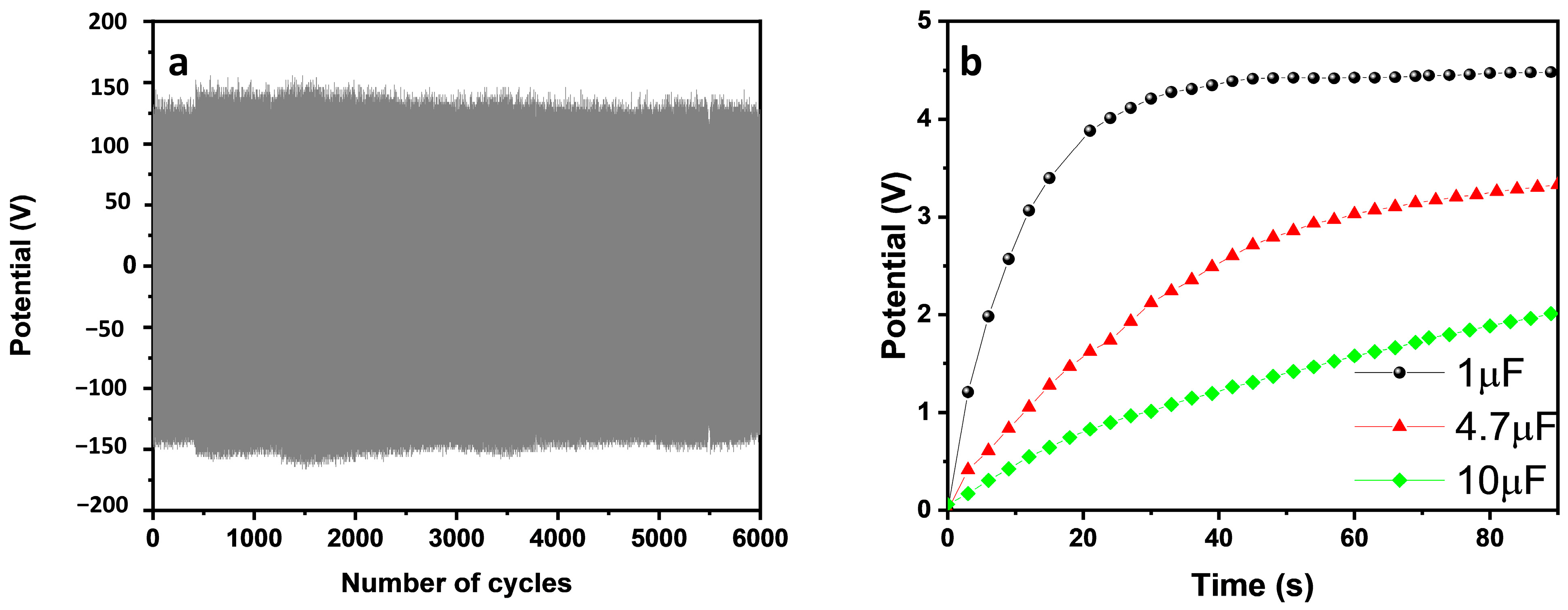
In addition to the electrical output performance for the produced bio-TENGs, the retention of the output parameters after cycles of operation and the ability to operate external devices are desirable properties to be considered in the prepared device. To evaluate these properties, the TENG (with 12 wt% of cb in BC) was operated at a frequency of 7 Hz under successive cycles of excitation. The results in Figure 5a indicate that a negligible variation in the output voltage is observed after 6000 cycles of operation, confirming the long-term retention in the performance of the TENG.
Another important property to be considered is the ability of the TENG to transfer energy to conventional energy storage devices, such as capacitors. The pumping of energy to a capacitor was evaluated for three different capacitors with the capacitance values of 1 μF, 4.7 μF, and 10 μF, respectively, as shown in Figure 5b. As can be seen, a faster charge rate was observed for lower capacitance devices, as a consequence of the lower charge (Q = CV) required to be separated between plates. Consequently, an accumulated voltage level above 4 V was reached after 90 s of operation of the TENG on the plates of a capacitor of 1 μF.

4. Conclusions

Developing metal-free electrodes for TENGs depends on the percolation threshold condition for conductive fillers incorporated into support. In particular, the production of bacterial cellulose membranes impregnated with carbon black reached an adequate condition for use at the relative concentration of 12 wt%; above this level, a saturation in the short-circuit current was observed for the produced TENG. The assembled devices in the single-electrode configuration using Ecoflex as the tribonegative friction layer and PLA as the tribopositive support presented the best performance in terms of energy harvesting with an open-circuit voltage value of 102.3 V, short-circuit current of 2 µA, and power density of 4.89 μW/cm2. A negligible variation in the output generation after 6000 cycles of operation and the ability to charge conventional capacitors are some of the critical properties of this free-of-metal bio-TENG.

Supplementary Materials

The following supporting information can be downloaded at: https://www.mdpi.com/article/10.3390/nanoenergyadv4010006/s1. Figure S1. (a) TGA curves and (b) FTIR spectrum for the pristine BC and BC/carbon black with relative carbon black content amounts of 1, 3, 6, 9, and 12 wt%; Figure S2. DTG curves of the pristine BC and with the increase in the concentrations of the conductive filler (carbon black) BC-1 wt%, BC-3 wt%, BC-6 wt%, BC-9 wt%, and BC-12 wt%; Figure S3. Raman spectra of (a) carbon black (black), BC (blue), (b) BC_cb 1%, (c) BC_cb 3%, (d) BC_cb 6%, (e) BC_cb 9%, and BC_cb 12%. (b–f) are depicted at three different positions over the sample surface; Table S1. Intensity ratio between the carbon D and G bands; Figure S4. Stress–strain curves for the electrodes of the bacterial cellulose prepared with increasing content amounts of carbon black; Figure S5 Short-circuit current for the bio-TENG with the modified bacterial cellulose produced with increasing content amounts of the additive filler and excited at 3 Hz (a), 5 Hz (b), and 7 Hz (c) and the average of the peaks as a function of the additive content and frequency of operation (d); Figure S6. Transferred charge per cycle calculated using the short-circuit current of the different devices ((a) 1 wt%, (b) 3 wt%, (c) 6 wt%, (d) 9 wt%, and (e) 12 wt%) at different frequencies of operation; Figure S7. (a) Overall dependence of the voltage output and current as a function of the loading resistance and (b) the corresponding variation in the power output for the bio-TENG.

Author Contributions

Conceptualization, H.S.B., H.P.d.O., L.G.S., A.L.F., L.R.L. and I.C.M.C.; methodology, H.S.B., T.L.O., H.P.d.O., L.G.S., A.L.F., L.R.L. and I.C.M.C.; investigation, L.F.C.d.O., T.L.O., L.G.S., A.L.F., L.R.L., I.C.M.C. and H.P.d.O.; writing—original draft preparation, H.S.B., T.L.O., H.P.d.O., L.G.S., A.L.F., L.R.L., and I.C.M.C.; writing—review and editing, H.P.d.O. and H.S.B.; visualization, H.P.d.O., H.S.B., L.F.C.d.O., E.C. and S.J.L.R.; supervision, H.P.d.O., H.S.B., L.F.C.d.O., E.C. and S.J.L.R.; project administration, H.P.d.O., H.S.B., L.F.C.d.O., E.C. and S.J.L.R.; funding acquisition, H.P.d.O., H.S.B., E.C., and S.J.L.R. All authors have read and agreed to the published version of the manuscript.

Funding

This research was funded by CAPES, FACEPE, FAPESB, FAPEMIG, and CNPq. H.S.B. thanks CNPq (Grant No. 309614/2021-0; INCT-INFO), São Paulo Research Foundation (FAPESP) (Grant No. 2013/07276-1), and INCT/Polysaccharides (National Technology-Science Institute for Polysaccharides) and Anton Paar Company. E.C. thanks CNPq (Grant No. 409215/2022-8) for funds and fellowship to L.R.L. H.P.O. thanks CNPq (Grant No. 303997/2021-4) for the funds.

Data Availability Statement

The original contributions presented in the study are included in the article/supplementary material, further inquiries can be directed to the corresponding author.

Conflicts of Interest

The authors declare no conflicts of interest.

References

  1. Yu, H.; Shao, Y.; Luo, C.; Li, Y.; Ma, H.; Zhang, Y.; Yin, B.; Shen, J.; Yang, M. Bacterial Cellulose Nanofiber Triboelectric Nanogenerator Based on Dielectric Particles Hybridized System. Compos. Part A Appl. Sci. Manuf. 2021, 151, 106646. [Google Scholar] [CrossRef]
  2. Park, S.; Vosguerichian, M.; Bao, Z. A Review of Fabrication and Applications of Carbon Nanotube Film-Based Flexible Electronics. Nanoscale 2013, 5, 1727–1752. [Google Scholar] [CrossRef] [PubMed]
  3. Jakmuangpak, S.; Prada, T.; Mongkolthanaruk, W.; Harnchana, V.; Pinitsoontorn, S. Engineering Bacterial Cellulose Films by Nanocomposite Approach and Surface Modification for Biocompatible Triboelectric Nanogenerator. ACS Appl. Electron. Mater. 2020, 2, 2498–2506. [Google Scholar] [CrossRef]
  4. Wang, X.; Tao, Y.; Pan, S.; Fang, X.; Lou, C.; Xu, Y.; Wu, J.; Sang, M.; Lu, L.; Gong, X.; et al. Biocompatible and Breathable Healthcare Electronics with Sensing Performances and Photothermal Antibacterial Effect for Motion-Detecting. NPJ Flex. Electron. 2022, 6, 95. [Google Scholar] [CrossRef]
  5. Choi, S.M.; Rao, K.M.; Zo, S.M.; Shin, E.J.; Han, S.S. Bacterial Cellulose and Its Applications. Polymers 2022, 14, 1080. [Google Scholar] [CrossRef] [PubMed]
  6. Candido, I.C.M.; Oliveira, G.d.S.; Ribeiro, S.J.L.; Cavicchioli, M.; Barud, H.S.; Silva, L.G.; de Oliveira, H.P. PVA-Silk Fibroin Bio-Based Triboelectric Nanogenerator. Nano Energy 2023, 105, 108035. [Google Scholar] [CrossRef]
  7. Candido, I.C.M.; Piovesan, L.F.; Freire, A.L.; Fotius, J.A.A.; de Lima, J.J.I.; Barud, H.S.; de Oliveira, H.P. Biodegradable Hyaluronic Acid-Based Triboelectric Nanogenerator as Self-Powered Temperature Sensor. Mater. Today Commun. 2023, 36, 106855. [Google Scholar] [CrossRef]
  8. Candido, I.C.M.; Oliveira, G.d.S.; Lima, R.M.A.P.; de Lima, J.J.I.; de Oliveira, H.P. All-Silicone Rubber Triboelectric Nanogenerators with Graphite-Impregnated Electrodes. ACS Appl. Eng. Mater. 2023, 1, 1069–1078. [Google Scholar] [CrossRef]
  9. Zhang, S.; Chi, M.; Mo, J.; Liu, T.; Liu, Y.; Fu, Q.; Wang, J.; Luo, B.; Qin, Y.; Wang, S.; et al. Bioinspired Asymmetric Amphiphilic Surface for Triboelectric Enhanced Efficient Water Harvesting. Nat. Commun. 2022, 13, 4168. [Google Scholar] [CrossRef]
  10. Qin, Y.; Mo, J.; Liu, Y.; Zhang, S.; Wang, J.; Fu, Q.; Wang, S.; Nie, S. Stretchable Triboelectric Self-Powered Sweat Sensor Fabricated from Self-Healing Nanocellulose Hydrogels. Adv. Funct. Mater. 2022, 32, 2201846. [Google Scholar] [CrossRef]
  11. Lu, D.; Liu, T.; Meng, X.; Luo, B.; Yuan, J.; Liu, Y.; Zhang, S.; Cai, C.; Gao, C.; Wang, J.; et al. Wearable Triboelectric Visual Sensors for Tactile Perception. Adv. Mater. 2023, 35, e2209117. [Google Scholar] [CrossRef] [PubMed]
  12. Athirah Raihana Nor Aziz Hashim, N.; Zakaria, J.; Mohamad, S.; Fathiyah Sy Mohamad, S.; Rahim, M.H.A. Effect of Different Treatment Methods on the Purification of Bacterial Cellulose Produced from OPF Juice by Acetobacter Xylinum. IOP Conf. Ser. Mater. Sci. Eng. 2021, 1092, 012058. [Google Scholar] [CrossRef]
  13. Mule, A.R.; Dudem, B.; Patnam, H.; Graham, S.A.; Yu, J.S. Wearable Single-Electrode-Mode Triboelectric Nanogenerator via Conductive Polymer-Coated Textiles for Self-Power Electronics. ACS Sustain. Chem. Eng. 2019, 7, 16450–16458. [Google Scholar] [CrossRef]
  14. Fooladi, S.; Nematollahi, M.H.; Rabiee, N.; Iravani, S. Bacterial Cellulose-Based Materials: A Perspective on Cardiovascular Tissue Engineering Applications. ACS Biomater. Sci. Eng. 2023, 9, 2949–2969. [Google Scholar] [CrossRef]
  15. Li, G.; Wang, L.; Deng, Y.; Wei, Q. Research Progress of the Biosynthetic Strains and Pathways of Bacterial Cellulose. J. Ind. Microbiol. Biotechnol. 2022, 49, kuab071. [Google Scholar] [CrossRef]
  16. Luo, C.; Shao, Y.; Yu, H.; Ma, H.; Zhang, Y.; Yin, B.; Yang, M. Improving the Output Performance of Bacterial Cellulose-Based Triboelectric Nanogenerators by Modulating the Surface Potential in a Simple Method. ACS Sustain. Chem. Eng. 2022, 10, 13050–13058. [Google Scholar] [CrossRef]
  17. Lin, S.-P.; Loira Calvar, I.; Catchmark, J.M.; Liu, J.-R.; Demirci, A.; Cheng, K.-C. Biosynthesis, Production and Applications of Bacterial Cellulose. Cellulose 2013, 20, 2191–2219. [Google Scholar] [CrossRef]
  18. Zhang, R.; Dahlström, C.; Zou, H.; Jonzon, J.; Hummelgård, M.; Örtegren, J.; Blomquist, N.; Yang, Y.; Andersson, H.; Olsen, M.; et al. Cellulose-Based Fully Green Triboelectric Nanogenerators with Output Power Density of 300 W m−2. Adv. Mater. 2020, 32, 2002824. [Google Scholar] [CrossRef]
  19. Shao, Y.; Feng, C.; Deng, B.; Yin, B.; Yang, M. Facile Method to Enhance Output Performance of Bacterial Cellulose Nanofiber Based Triboelectric Nanogenerator by Controlling Micro-Nano Structure and Dielectric Constant. Nano Energy 2019, 62, 620–627. [Google Scholar] [CrossRef]
  20. Boonchai, N.; Mongkolthanaruk, W.; Harnchana, V.; Faungnawakij, K.; Pinitsoontorn, S. Chemical Functionalization of Bacterial Cellulose Film for Enhancing Output Performance of Bio-Triboelectric Nanogenerator. Biointerface Res. Appl. Chem. 2021, 12, 1587–1600. [Google Scholar]
  21. Hwang, H.; Lee, K.Y.; Shin, D.; Shin, J.; Kim, S.; Choi, W. Metal-Free, Flexible Triboelectric Generator Based on MWCNT Mesh Film and PDMS Layers. Appl. Surf. Sci. 2018, 442, 693–699. [Google Scholar] [CrossRef]
  22. Burmistrov, I.; Gorshkov, N.; Ilinykh, I.; Muratov, D.; Kolesnikov, E.; Anshin, S.; Mazov, I.; Issi, J.-P.; Kusnezov, D. Improvement of Carbon Black Based Polymer Composite Electrical Conductivity with Additions of MWCNT. Compos. Sci. Technol. 2016, 129, 79–85. [Google Scholar] [CrossRef]
  23. Mallineni, S.S.K.; Behlow, H.; Podila, R.; Rao, A.M. A Low-Cost Approach for Measuring Electrical Load Currents in Triboelectric Nanogenerators. Nanotechnol. Rev. 2018, 7, 149–156. [Google Scholar] [CrossRef]
  24. Yang, M.; Ward, J.; Choy, K. Nature-Inspired Bacterial Cellulose/Methylglyoxal (BC/MGO) Nanocomposite for Broad-Spectrum Antimicrobial Wound Dressing. Macromol. Biosci. 2020, 20, 2000070. [Google Scholar] [CrossRef] [PubMed]
  25. Sharma, H.N.; Pahalagedara, L.; Joshi, A.; Suib, S.L.; Mhadeshwar, A.B. Experimental Study of Carbon Black and Diesel Engine Soot Oxidation Kinetics Using Thermogravimetric Analysis. Energy Fuels 2012, 26, 5613–5625. [Google Scholar] [CrossRef]
  26. Barud, H.S.; Souza, J.L.; Santos, D.B.; Crespi, M.S.; Ribeiro, C.A.; Messaddeq, Y.; Ribeiro, S.J.L. Bacterial Cellulose/Poly(3-Hydroxybutyrate) Composite Membranes. Carbohydr. Polym. 2011, 83, 1279–1284. [Google Scholar] [CrossRef]
  27. Lima, L.R.; Conte, G.V.; Brandão, L.R.; Sábio, R.M.; de Menezes, A.S.; Resende, F.A.; Caiut, J.M.A.; Ribeiro, S.J.L.; Otoni, C.G.; Alcântara, A.C.S.; et al. Fabrication of Noncytotoxic Functional Siloxane-Coated Bacterial Cellulose Nanocrystals. ACS Appl. Polym. Mater. 2022, 4, 2306–2313. [Google Scholar] [CrossRef]
  28. Gomes, R.J.; Ida, E.I.; Spinosa, W.A. Nutritional Supplementation with Amino Acids on Bacterial Cellulose Production by Komagataeibacter Intermedius: Effect Analysis and Application of Response Surface Methodology. Appl. Biochem. Biotechnol. 2022, 194, 5017–5036. [Google Scholar] [CrossRef]
  29. Wang, S.-S.; Han, Y.-H.; Ye, Y.-X.; Shi, X.-X.; Xiang, P.; Chen, D.-L.; Li, M. Physicochemical Characterization of High-Quality Bacterial Cellulose Produced by Komagataeibacter Sp. Strain W1 and Identification of the Associated Genes in Bacterial Cellulose Production. RSC Adv. 2017, 7, 45145–45155. [Google Scholar] [CrossRef]
  30. Shim, E.; Silva, C.; Cavaco-Paulo, A.; Kim, H.R. Effects of the Modification of Bacterial Cellulose as a Template for the in Situ Enzyme-Catalyzed Polymerization of Catechol. Text. Res. J. 2023, 93, 3588–3599. [Google Scholar] [CrossRef]
  31. Gruber, T.; Zerda, T.W.; Gerspacher, M. Raman Studies of Heat-Treated Carbon Blacks. Carbon 1994, 32, 1377–1382. [Google Scholar] [CrossRef]
  32. Cançado, L.G.; Jorio, A.; Ferreira, E.H.M.; Stavale, F.; Achete, C.A.; Capaz, R.B.; Moutinho, M.V.O.; Lombardo, A.; Kulmala, T.S.; Ferrari, A.C. Quantifying Defects in Graphene via Raman Spectroscopy at Different Excitation Energies. Nano Lett. 2011, 11, 3190–3196. [Google Scholar] [CrossRef]
  33. Blackwell, J. Infrared and Raman Spectroscopy of Cellulose. In Cellulose Chemistry and Technology; American Chemical Society: Washington, DC, USA, 1977; pp. 206–218. [Google Scholar]
  34. Proniewicz, L.M.; Paluszkiewicz, C.; Wesełucha-Birczyńska, A.; Majcherczyk, H.; Barański, A.; Konieczna, A. FT-IR and FT-Raman Study of Hydrothermally Degradated Cellulose. J. Mol. Struct. 2001, 596, 163–169. [Google Scholar] [CrossRef]
  35. Satha, H.; Kouadri, I.; Benachour, D. Thermal, Structural and Morphological Studies of Cellulose and Cellulose Nanofibers Extracted from Bitter Watermelon of the Cucurbitaceae Family. J. Polym. Environ. 2020, 28, 1914–1920. [Google Scholar] [CrossRef]
  36. Stanisławska, A. Bacterial Nanocellulose as a Microbiological Derived Nanomaterial. Adv. Mater. Sci. 2016, 16, 45–57. [Google Scholar] [CrossRef]
  37. Yu, K.; Balasubramanian, S.; Pahlavani, H.; Mirzaali, M.J.; Zadpoor, A.A.; Aubin-Tam, M.-E. Spiral Honeycomb Microstructured Bacterial Cellulose for Increased Strength and Toughness. ACS Appl. Mater. Interfaces 2020, 12, 50748–50755. [Google Scholar] [CrossRef]
  38. Petersen, N.; Gatenholm, P. Bacterial Cellulose-Based Materials and Medical Devices: Current State and Perspectives. Appl. Microbiol. Biotechnol. 2011, 91, 1277–1286. [Google Scholar] [CrossRef] [PubMed]
  39. Choi, H.-J.; Kim, M.S.; Ahn, D.; Yeo, S.Y.; Lee, S. Electrical Percolation Threshold of Carbon Black in a Polymer Matrix and Its Application to Antistatic Fibre. Sci. Rep. 2019, 9, 6338. [Google Scholar] [CrossRef] [PubMed]
  40. Kim, H.-J.; Yim, E.-C.; Kim, J.-H.; Kim, S.-J.; Park, J.-Y.; Oh, I.-K. Bacterial Nano-Cellulose Triboelectric Nanogenerator. Nano Energy 2017, 33, 130–137. [Google Scholar] [CrossRef]
  41. Zhang, J.; Hu, S.; Shi, Z.; Wang, Y.; Lei, Y.; Han, J.; Xiong, Y.; Sun, J.; Zheng, L.; Sun, Q.; et al. Eco-Friendly and Recyclable All Cellulose Triboelectric Nanogenerator and Self-Powered Interactive Interface. Nano Energy 2021, 89, 106354. [Google Scholar] [CrossRef]
  42. Huang, J.; Hao, Y.; Zhao, M.; Qiao, H.; Huang, F.; Li, D.; Wei, Q. Biomass-Based Wearable and Self-Powered Pressure Sensor for Human Motion Detection. Compos. Part A Appl. Sci. Manuf. 2021, 146, 106412. [Google Scholar] [CrossRef]
  43. Fatma, B.; Andrabi, S.M.; Gupta, S.; Verma, V.; Kumar, A.; Pitsalidis, C.; Garg, A. Biocompatible, Breathable and Degradable Microbial Cellulose Based Triboelectric Nanogenerator for Wearable Transient Electronics. Nano Energy 2023, 114, 108628. [Google Scholar] [CrossRef]
  44. Li, M.; Jie, Y.; Shao, L.H.; Guo, Y.; Cao, X.; Wang, N.; Wang, Z.L. All-in-One Cellulose Based Hybrid Tribo/Piezoelectric Nanogenerator. Nano Res. 2019, 12, 1831–1835. [Google Scholar] [CrossRef]
  45. Hu, S.; Han, J.; Shi, Z.; Chen, K.; Xu, N.; Wang, Y.; Zheng, R.; Tao, Y.; Sun, Q.; Wang, Z.L.; et al. Biodegradable, Super-Strong, and Conductive Cellulose Macrofibers for Fabric-Based Triboelectric Nanogenerator. Nano-Micro Lett. 2022, 14, 115. [Google Scholar] [CrossRef] [PubMed]
Disclaimer/Publisher’s Note: The statements, opinions, and data contained in all publications are solely those of the individual author(s) and contributor(s) and not of MDPI and/or the editor(s). MDPI and/or the editor(s) disclaim responsibility for any injury to people or property resulting from any ideas, methods, instructions, or products referred to in the content.
Figure 1. General scheme for the disposition of the mechanical exciter systems and the assembled TENG, composed by a 3D-printed plate of polylactic acid (PLA) used as a tribopositive layer and a tribonegative layer of Ecoflex applied on a 4 cm × 4 cm membrane of bacterial cellulose with different contents of the conductive filler. The working mechanism is illustrated in a complete cycle of contact–separation of tribopairs.
Nanoenergyadv 04 00006 g001
Figure 2. SEM images with a magnification of 10 kx for the bacterial cellulose membranes prepared with increasing amounts of content of the conductive filler (carbon black): pure (a), BC-1 wt% (b), BC-3 wt% (c), BC-6 wt% (d), BC-9 wt% (e), and BC-12 wt% (f).
Nanoenergyadv 04 00006 g002
Figure 3. (a) Real part of the impedance of the BC membranes with different content amounts of the conductive filler (from 1 wt% to 12 wt%), (b) Nyquist plot for the samples, and (c) conductance of the samples as a function of the content of the conductive filler, with the identification of region I (non-ohmic behavior), percolation threshold, and region II (ohmic behavior).
Nanoenergyadv 04 00006 g003
Figure 4. Open-circuit voltage for the bio-TENG based on modified bacterial cellulose with increasing content amounts of the additive filler excited at 3 Hz (a), 5 Hz (b), and 7 Hz (c), and the average of the peaks as a function of the additive content and frequency of operation (d).
Nanoenergyadv 04 00006 g004
Figure 5. (a) Overall retention in the voltage output after 6000 cycles of operation of the TENG and (b) the corresponding charge profiles of 1 μF (curve in black), 4.7 μF (curve in red), and 10 μF (curve in green) after 90 s of operation of the TENG.
Nanoenergyadv 04 00006 g005
Table 1. Vibrational assignment (Raman and infrared spectra) for the investigated chemical systems.
IR (cm−1)Raman (cm−1)Assignments
33403339νs (O–H)
29002896νs (C–H)
1640-ν (C=C)
-1481δ (C–O–H)
14251460δ (CH)
-1411δ (C–O–H) and (C–C–H)
-1380δ (CH)
13201339δ (CH2) and (C–O–H)
-1293δ (CC)
11601152νas (C–O–C)
11101122δ (C–O–H)
-1098νs (C–C) and δ (C–O–H), δ (C–C–H)
10501061δ (C–C–H)
10301036δ (C–O–H)
Table 2. Comparison of the output voltage, short-circuit current, and power density for the TENG reported in this work and related values for bacterial cellulose-based TENGs reported in the literature.
BC-Based Active LayerElectrodeConfigurationVoltageCurrentPowerRef.
BC Cu Vertical contact–separation 13 V 3 μA 4.8 mW/m2[40]
Silver nanowires and BaTiO3 in BCCuVertical contact–separation87 V7.1 μA75 μW/cm 2[1]
Dip-coated hydroxyethyl celluloseCuVertical contact–separation76.6 V8.68 μA290.7 μW[16]
BCBC/CNT/PPySingle electrode29 V0.6 μA3 μW[41]
BC/ZnOITOSingle electrode57.6 V5.78 μA42 mW/m2[3]
BaTiO3-doped BCCuVertical contact–separation181 V21 μA4.8 W/m2[19]
Bacterial cellulose/chitosan Cu Vertical contact–separation23 V500 nA3.3 mW/m2[42]
Polydopamine-coated bacterial cellulose MWCNT/BC Single electrode1010 V-8.7 W/m2[43]
Nitrocellulose/BaTiO3/MWCNT Cu Vertical contact–separation37 V1.23 μA10.6 μW/cm2[44]
Nylon BC/CNT/PPy Single electrode170 V7.5 μA352 μW[45]
Polylactic acid BC/carbon black Single electrode102.3 V2 μA48.9 mW/m2This work
Disclaimer/Publisher’s Note: The statements, opinions and data contained in all publications are solely those of the individual author(s) and contributor(s) and not of MDPI and/or the editor(s). MDPI and/or the editor(s) disclaim responsibility for any injury to people or property resulting from any ideas, methods, instructions or products referred to in the content.