The authors wish to make the following corrections to this paper [1]:
Error in Figure
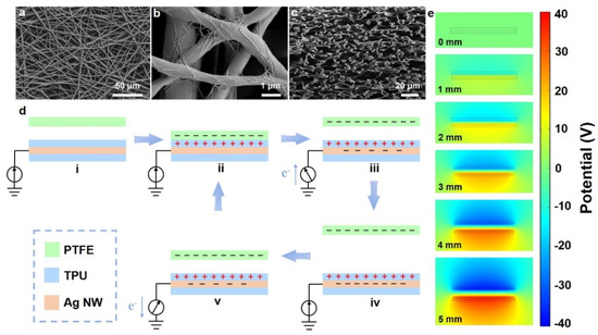
In the original publication, there was a mistake in Figure 2. We reversed the charge on the surface of the PTFE and the TPU in Figure 2d, and the parameters in the COMSOL simulation were also set incorrectly, leading to a wrong result in Figure 2e. The corrected version of Figure 2 is provided below.

Figure 2.
The micromorphologies and working mechanism of the TE-skin. (a) The SEM image of the TPU layer. (b) The SEM image of the Ag NW that is deposited on the TPU fibers. (c) The cross-section SEM image of the TE-skin. (d) The working mechanism of the TE-skin upon contact with skin. (e) The potential simulation by COMSOL to elucidate the working principle of the TE-skin.
Text Correction
There was an error in the original publication. As described in Section 3.2 of the paper, “…wherein the PTFE is electronegative in comparison with the TPU, due to the diverse triboelectric polarities”. However, the following writing of “Due to its ability to attract more electrons, the TPU will be negatively charged, whereas the PTFE will be positively charged in this period” is wrong, leading to an incorrect direction of electron flow in the content of the paper. A correction has been made to Section 3.2, Paragraph 1:
By using an electrospinning technique, the two TPU layers present a typical stacked-fiber structure (Figure 2a,c), with a corresponding average fiber diameter of 1.9 μm (Supplementary Figure S4). In addition, the Ag NW electrode layer is uniformly distributed over the surface of the TPU fibers by spraying (Figure 2b), which process constructs excellent conductive networks. The energy-dispersive spectrometer (EDS) mapping images (Supplementary Figure S5) further confirm this pivotal result. In addition, the TE-skin has numerous micro/nanopores that are formed by the multilayer interconnected compact fiber networks, ensuring good breathability. To explain the working mechanism of the TE-skin in detail, polytetrafluoroethylene (PTFE) film was adopted in order to have a contact-separation process with the TE-skin in single-electrode mode (Figure 2d), wherein the PTFE is electronegative in comparison with the TPU, due to the diverse triboelectric polarities. Once the TPU is in contact with the PTFE, electrification will occur at their interface, and an equal number of charges with opposite polarities will be generated on the surface of the TPU and PTFE. Due to its ability to attract more electrons, the PTFE will be negatively charged, whereas the TPU will be positively charged in this period (Figure 2d, ii). As the PTFE begins to separate from the TPU, a potential difference is formed. Owing to the electrostatic induction effect, the negative charges will be transferred from the ground to the Ag NW conductive networks (Figure 2d, iii). The electron flow continues until the separation between the PTFE and the TPU is complete; the positive and negative charges are neutralized during this process (Figure 2d, iv). Notably, the accumulated charges will be retained for a sufficiently long time due to the inherent characteristic of the insulator, rather than being lost immediately. In contrast, if the PTFE is close to the TPU, the electrons will flow back from the Ag NW conductive networks to the ground through the external load, compensating for the electrical potential differences (Figure 2d, v) until the whole system reverts to its original state. As a result, an alternating potential and current are produced in the contact–separation process occurring between the PTFE and the TE-skin. To assess the electricity-generating process quantitatively, the COMSOL was utilized to simulate the potential distribution result of the PTFE and the TE-skin in different contact and separation processes. Figure 2e shows that the potential difference will grow moderately from 0 to 80 V with an increase in the separation distance between the PTFE and the TE-skin from 0 to 5 mm.
There was an error in the original publication. We missed a letter in Equation (2). The pressure sensitivity of the TE-skin is represented as “S”. A correction has been made to Section 3.3, Paragraph 2:
The pressure sensitivity of the TE-skin (S) as a function of the loading force was also explored, which is calculated as follows:
The authors apologize for any inconvenience caused and confirm that the scientific conclusions are unaffected. This correction was approved by the Academic Editor. The original publication has also been updated.
Reference
- Shi, Y.; Ding, T.; Yuan, Z.; Li, R.; Wang, B.; Wu, Z. Ultrathin Stretchable All-Fiber Electronic Skin for Highly Sensitive Self-Powered Human Motion Monitoring. Nanoenergy Adv. 2022, 2, 52–63. [Google Scholar]
Publisher’s Note: MDPI stays neutral with regard to jurisdictional claims in published maps and institutional affiliations. |
© 2022 by the authors. Licensee MDPI, Basel, Switzerland. This article is an open access article distributed under the terms and conditions of the Creative Commons Attribution (CC BY) license (https://creativecommons.org/licenses/by/4.0/).