Article

A Near-Zero Power Triboelectric Wake-Up System for Autonomous Beaufort Scale of Wind Force Monitoring

1
CAS Center for Excellence in Nanoscience, Beijing Key Laboratory of Micro-Nano Energy and Sensor, Beijing Institute of Nanoenergy and Nanosystems, Chinese Academy of Sciences, Beijing 101400, China
2
School of Nanoscience and Technology, University of Chinese Academy of Sciences, Beijing 100049, China
3
School of Mechanical Engineering, Guangxi University, Nanning 530004, China
4
Center on Nanoenergy Research, School of Physical Science and Technology, Guangxi University, Nanning 530004, China
5
Tribotronics Research Group, Beijing Institute of Nanoenergy and Nanosystems, Chinese Academy of Sciences, Beijing 100029, China
*
Author to whom correspondence should be addressed.
Nanoenergy Adv. 2021, 1(2), 121-130; https://doi.org/10.3390/nanoenergyadv1020006
Submission received: 12 May 2021 / Revised: 18 July 2021 / Accepted: 17 September 2021 / Published: 1 October 2021
(This article belongs to the Special Issue Recent Advances in Nanogenerators)

Abstract

:
Beaufort scale of wind force monitoring is the basic content of meteorological monitoring, which is an important means to ensure the safety of production and life by timely warning of natural disasters. As there is a limited battery life for sensors, determining how to reduce power consumption and extend system life is still an urgent problem. In this work, a near-zero power triboelectric wake-up system for autonomous Beaufort scale of wind force monitoring is proposed, in which a rotary TENG is used to convert wind energy into a stored electric energy capacitor. When the capacitor voltage accumulates to the threshold voltage of a transistor, it turns on as an electronic switch and the system wakes up. In active mode, the Beaufort scale of wind force can be judged according to the electric energy and the signal is sent out wirelessly. In standby mode, when there is no wind, the power consumption of the system is only 14 nW. When the wind scale reaches or exceeds light air, the system can switch to active mode within one second and accurately judge the Beaufort scale of wind force within 10 s. This work provided a triboelectric sensor-based wake-up system with ultralow static power consumption, which has great prospects for unattended environmental monitoring, hurricane warning, and big data acquisition.

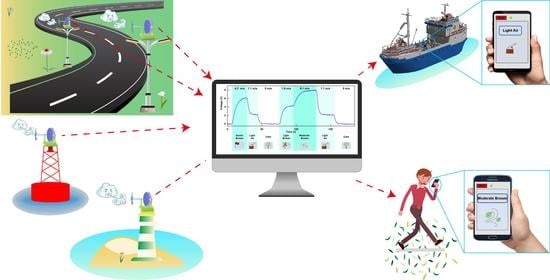
Graphical Abstract

1. Introduction

Beaufort scale of wind force monitoring is an important meteorological predicting technology, which has been widely used in guiding production and preventing natural disasters [1]. For example, in the early warning of marine storms, the Beaufort scale is one of the important parameters in predicting typhoons. However, the conventional Beaufort scale monitoring systems of wind force cannot keep running for a long time because batteries continuously power most sensors, leading to a short lifetime and high maintenance costs. In order to improve the lifespan of the monitoring systems, the project of “Near Zero Power RF and Sensor Operations (N-ZERO)” was proposed by the Defense Advanced Research Projects Agency (DARPA) in 2015 [2], which aims to develop near-zero power systems. To further reduce energy consumption, the auto-wakeup system is proposed based on various active sensors [3,4,5,6,7]. In 2017, Robert W. Reger. et al. proposed a near-zero power wakeup system based on a complementary metal–oxide-semiconductor comparator (CMOS) and a piezoelectric microelectromechanical accelerometer, in which the system can be awakened by threshold acceleration [8]. In the same year, a near-zero power sensing system awakened by sound was proposed, by coupling a piezoelectric sensor with low-power CMOS circuits [9]. In 2019 and 2020, Venkateswaran Vivekananthan and his coauthors designed and fabricated a triboelectrification based energy collector, which realized the function of zero-power consuming seismic detection and a zero-power consuming active pressure sensor, the reported result brought the self-power electronic device into zero-power or near-zero power mode [10,11]. In 2021, Chenxi Zhang et, al proposed a near-zero power system awakened by touch based on the triboelectrification effect, which demonstrated an ultralow quiescent power consumption wake-up technology [12]. With the advantages of a long lifespan and low maintenance costs, the auto-wakeup technology is promising for wind force monitoring.
In 2012, the triboelectric nanogenerator (TENG) was invented based on contact electrification and electrostatic induction [13,14,15], which can convert mechanical energy into electrical energy effectively [16,17,18]. At present, TENGs are widely used in self-powered systems [19,20,21], sensor array [22], and big data acquisition [23]. Previous studies have shown that the TENG can be used as active sensors for wind speed monitoring [24], such as the active wind sensor based on the flutter TENG [25,26], the self-powered wind sensing system based on the rotating TENG [27,28,29], the intelligent self-powered wireless wind sensing systems based on a single TENG [30], and so on. Nevertheless, the existing wind-driven TENGs-based sensing systems always remain in active mode for signal monitoring and measurement [31], which lead to continuous consumption of electrical energy. Constant power consumption neither conserves energy nor ensures that the system maximizes the use of power when transmitting signals. The mechanical energy collected from the natural environment is not enough to convert into electrical energy to power the sensing system all the time. Therefore, to extend the lifespan with low static power consumption, it is necessary to develop the TENG-based auto-wakeup system for wind force monitoring.
In this work, a near-zero power triboelectric wake-up system (NP-TWS) for autonomous Beaufort scale of wind force monitoring is proposed, in which a rotary TENG is used to convert wind energy into a stored electric energy capacitor. When the capacitor voltage accumulates to the threshold voltage of a transistor, it turns on as an electronic switch and the system wakes up. In active mode, the Beaufort scale of wind force can be judged according to the electric energy and the signal is sent out wirelessly. In standby mode when there is no wind, the power consumption of the system is only 14 nW. When the wind scale reaches or exceeds light air, the system can switch to the active mode within one second and accurately judge the Beaufort scale of wind force within 10 s. This work has provided a triboelectric sensor-based wake-up system with ultralow static power consumption, which has great prospects for unattended environmental monitoring, hurricane warning, and big data acquisition.

2. System Design and Characterization

2.1. Design of the System Framework

The NP-TWS for autonomous Beaufort scale of wind force monitoring consists of a rotating TENG, a wake-up circuit, and a stage circuit (SC), which is shown in Figure 1a. The TENG is used to convert wind energy into electric energy and stores it in a capacitor. Then, the wake-up circuit determines whether to wake up the system according to the capacitor voltage. If the system is not awakened, it remains in standby mode and maintains ultra-low static power consumption. Otherwise, the system will shift to active mode, in which the SC judges the Beaufort scale of wind force according to the comparison voltage of the storage capacitor and the signal is sent out wirelessly.

2.2. Structure and Characteristics of the Rotating TENG

As depicted in Figure 1b, the TENG in rotating freestanding-mode was designed as a wind energy harvester with nine fixed power generation units, which contain a stator and a rotator. The two 280 mm diameter acrylic disks with a center hole were divided into 18 fan shapes. The 18 fan shapes of the stator disk were covered with copper. A fan-shaped area was left between every two film coated areas, and the 9 fan shapes of the rotator were attached with fluorinated ethylene propylene (FEP). The stator and the rotor were connected through the shaft, and a fan blade was added in front of the rotor. The working principle of the freestanding-mode TENG is shown in Figure 1c. The FEP layer was in contact with the copper electrode in advance, and the same amount of heterogeneous charge was generated. During the rotation, a small gap is left between the two triboelectric layers, which can eliminate friction and extend the service life of the TENG. In the original state, the FEP layer was aligned with the left copper electrode. At this time, since the TENG was in an electrostatic equilibrium state, there was no current in the external circuit, as shown in Figure 1c (I). When the rotor started to rotate, the alignment area between the FEP and the left electrode was reduced, resulting in the generation of a potential difference, so electrons flowed from the right electrode to the left electrode through the external circuit, as shown in Figure 1c (II). This process would continue until the FEP layer is completely aligned with the right copper electrode, as shown in Figure 1c (III). Then, the alignment area between the FEP and the left electrode increased, which created a reverse current, as shown in Figure 1c (IV). The periodic movement of the FEP layer would generate periodic alternating current (AC) signals. When the wind speed was 4 m/s, the output voltage of TENG was 178 V, and the output current was 4 μA, the corresponding waveform is shown in Figure 1d,e, respectively. The output peak–peak open-circuit voltage and peak short-circuit current of TENG with the Beaufort scale of wind force at grades 1–4 is shown in Figure 1f. From light air to moderate breeze, the voltage of TENG hardly changed and stabilized at 178 V, while the current increased from 1 μA to 6 μA, and the current was positively correlated with the wind speed. The output power of TENG is shown in Figure S6. The durability test of TENG is shown in Figure S5. For 2500 s, the output voltage of TENG remained stable.

2.3. Mechanism and Characteristics of the Wake-Up Circuit

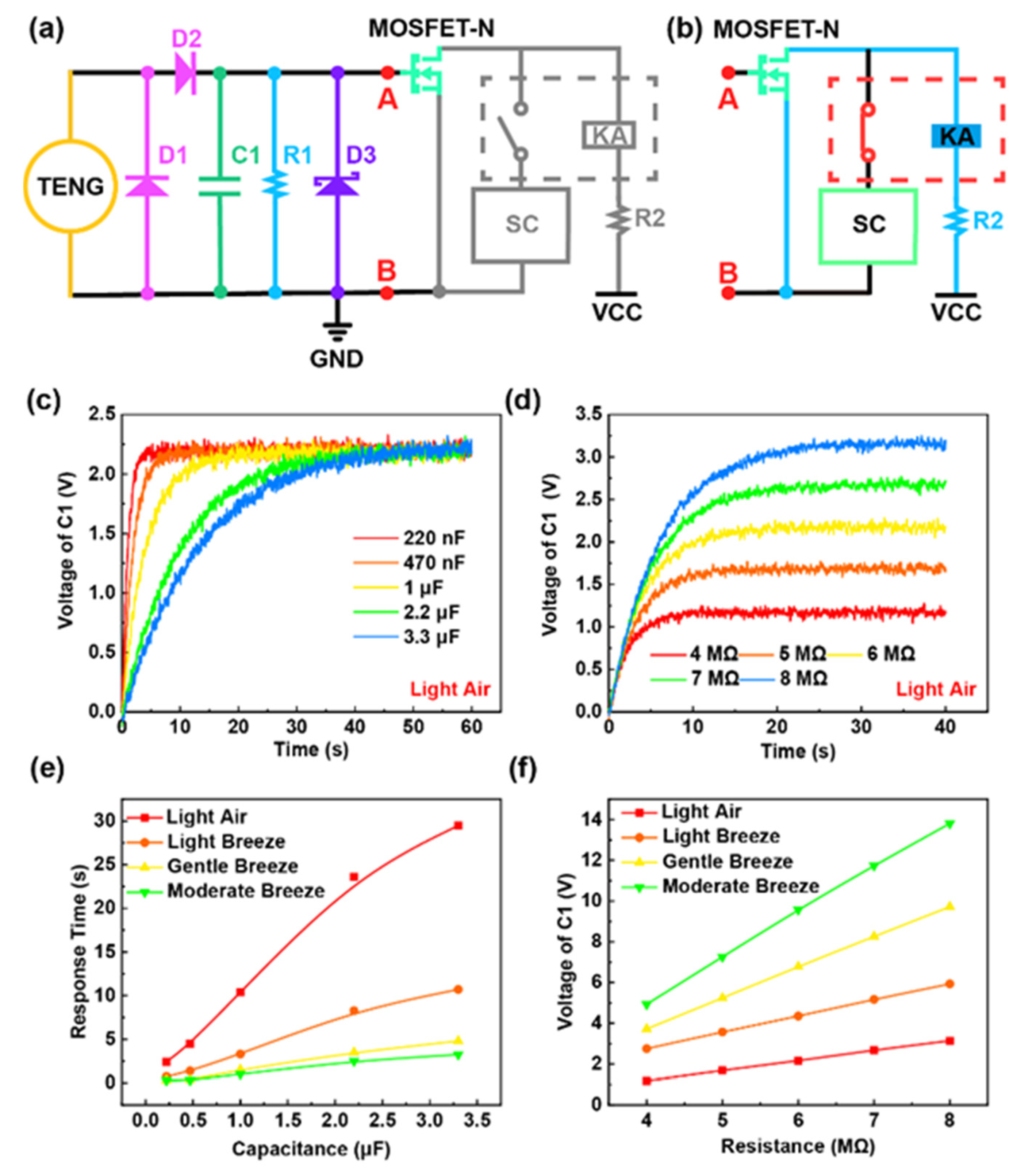
The circuit schematic diagram of the wake-up circuit is shown in Figure 2a, including a half-wave rectifier (D1, D2), a storage capacitor C1, a resistor R1, a zener diode D3, a MOSFET, and a relay. The AC signal output by TENG was converted into a DC signal by a half-wave rectifier composed of D1 and D2 and stored in the capacitor C1. When the voltage of C1 accumulated to the threshold voltage of MOSFET-N, it turned on as an electronic switch. Then current flowed through the coil of the relay KA, causing its switch to pull in and the system woke up, as shown in Figure 2b. With the resistor R1, the electrical energy stored in the capacitor C1 could be released to prevent the system from being triggered by mistake. The zener diode D3 was mainly used for overvoltage protection of MOSFET-N. In the same way, the resistor R2 was mainly used for overcurrent protection of relay KA.
The effects of the capacitance of C1 and the resistance of R1 on the voltage of C1 were studied systematically. The wind speed ranges corresponding to the Beaufort scale of wind force at grades 1–4 are shown in the Figure S1. Figure 2c illustrates the voltage of C1 with different capacitance in light air. The threshold voltage of the MOSFET-N set in the system was 2 V, so the time from 0 to 2 V of capacitor voltage was the response time of the system. The experiments results indicated that the response time of the system decreased along with decreasing the capacitance of C1. The voltage of the C1 with different resistance in light air is shown in Figure 2d, which indicated that the voltage of C1 increased along with increasing the resistance of R1. The voltage of the C1 with different capacitance and resistance on the Beaufort scale of wind force at grades 2–4 had the same result as above, as shown in Figure S2. Figure 2e summarizes the response times of the wake-up circuit with different capacitance on the Beaufort scale of wind force at grades 1–4. The experiment’s results indicated that the response time decreased with the decrease in the capacitance and the increase in the Beaufort scale of wind force. In order to avoid a rapid response causing the system to be awakened by mistake, when a burst of strong disturbance suddenly appears, while maintaining a fast response, a 1 μF capacitor was selected as an energy storage unit. In this case, the system can be awakened within one second and the voltage of C1 would tend to smooth within 10 s. The voltage of C1 with different resistance on the Beaufort scale of wind force at grades 1–4 is summarized in Figure 2f, which shows the increase in capacitor voltage not only increased with the resistance but also increased with the Beaufort scale of wind force. The power supply VCC was 10 V. A 6 MΩ resistor could meet the voltage of a capacitor between 2 and 10 V on the Beaufort scale of wind force at grades 1–4.

2.4. Mechanism and Characteristics of the Stage Circuit (SC)

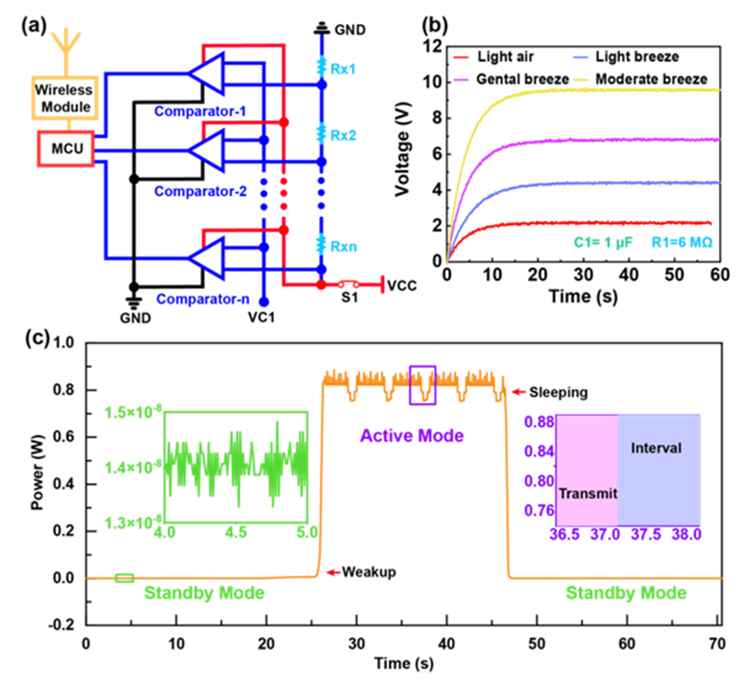
The circuit schematic diagram of the stage circuit (SC) is shown in Figure 3a, including comparators, resistors, the Microprogrammed Control Unit (MCU), and wireless module. In active mode, the power supply VCC connected to the SC. Resistors R1, R2..Rxn + 1 acted as resistor dividers to provide a threshold voltage for comparators, which were compared with the voltage of capacitor C1. The comparators output a signal of 0 or 1 according to the comparison of the two voltages. The MCU collected and processed the results and transmitted signals by wireless mode. In the experiment, a four-stage circuit was designed to monitor the Beaufort scale of wind force at grades 1–4. The comparison voltage on the Beaufort scale of wind force at grades 1–4 with 1 μF capacitor and a 6 MΩ resistor can be seen in Figure 3b, which shows that the comparison voltages tended to smooth at 2 V, 4 V, 6 V, and 8 V respectively. Considering the voltage fluctuation at the boundary of classification and the power supply VCC was 10 V, five resistors of 100 Ω in series could provide threshold voltages of 2 V, 4 V, 6 V, and 8 V for each of the four comparators. The output signal of the comparator is shown in Figure S3, which indicated that the system could distinguish the Beaufort scale of wind force at grades 1–4.

3. The Result and Discussion

3.1. The Power Consumption of the Wake-Up System

Since the purpose of the NP-TWS is to reduce static power consumption and thereby increase the battery life, the characteristic of the power consumption of the system was examined as shown in Figure 3c, and the power consumption was provided by the power supply VCC. In standby mode, there was only the leakage current of the MOSFET in the system, and the power consumption was just 14 nW, which demonstrated that the system had ultra-low static power consumption and could meet the requirements of low power consumption. In active mode, the power consumption was between 0.75 W and 0.88 W, which was caused by the wireless module. The power consumption would be higher when the wireless module sends data. When the system returned to the standby mode from the active mode, it maintained ultra-low static power consumption again.

3.2. Demonstration of Beaufort Scale of Wind Force Monitoring

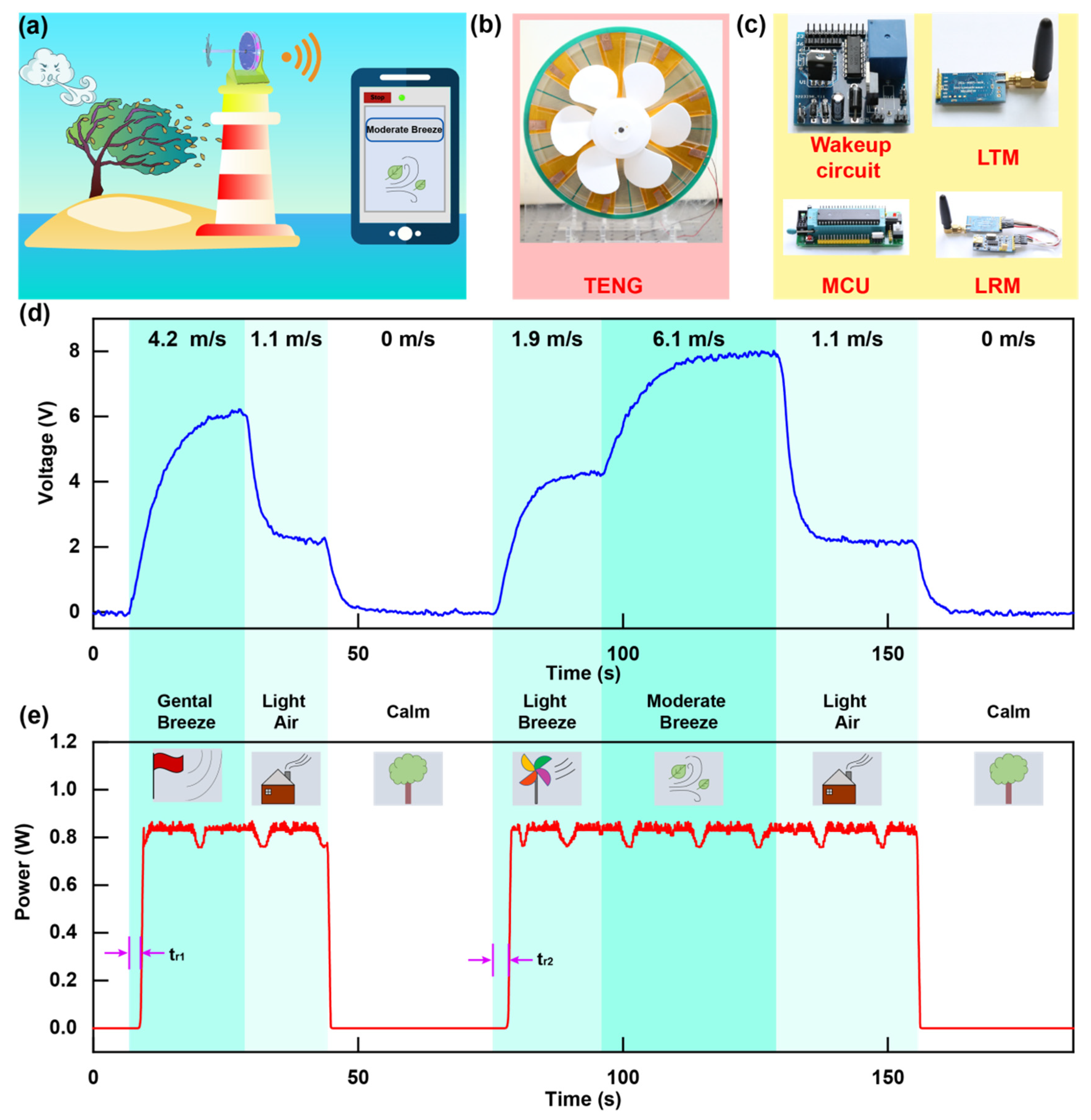
Verification experiments were demonstrated by utilizing this wake-up system to monitor the Beaufort scale of wind force. With the auto-wakeup technology, the NP-TWS realized the autonomous monitoring with ultra-low static power consumption and indicated potential application prospects for wind force monitoring, as shown in Figure 4a. Driven by wind energy, the NP-TWS can be used as a wireless sensor network node unattended and with a long lifetime. By monitoring the Beaufort scale of wind force, a large amount of data can be remotely sent to the terminal for wind information collection. The photos of the TENG, wake-up circuit, MCU, LoRa transmitter (LTM), and LoRa receiver (LRM) are shown in Figure 4b,c. Moreover, the flow chart of the NP-TWS is shown in Figure S4. As a demonstration, the compared voltage and system power consumption with different Beaufort scale of wind force are summarized in Figure 4d,e. The first part simulated the wind speed from 0 to 4.2 m/s in the external environment. Then the wind speed was changed to 1.1 m/s. Finally, the wind stopped blowing. In this process, the display on the terminal interface was “Calm”, “Gentle Breeze”, “Light Air” and “Calm”. The compared voltage measured also changed with the Beaufort scale of wind force and corresponded to the system monitoring results one by one. The power consumption of the system increased when the system was awake, and maintained near-zero power when there was no wind. In the second part, the system was kept in windless mode for a period of time, and the measurement results showed that the system could maintain ultralow static power consumption. Subsequently, we simulated the change of wind speed, which was 0, 1.9 m/s, 6.1 m/s, 1.1 m/s, and 0 in this order. The experimental results indicated that the display on the terminal interface, the comparison voltage, and the power consumption of the system were in line with expectations. In addition, the tr1 and tr2 shown in Figure 4e was the response time of the system.
In the experiments, the system is automatically awakened up when the wind blows and the Beaufort scale of wind force is displayed on the terminal device. Even if the Beaufort scale of wind force changes, the system can detect it immediately. When the wind stops blowing, the system will return to standby mode with ultralow static power consumption and wait for the next monitoring. The dynamic display of wake-up is shown in Video S1.

4. Experimental Section

The fabrication of rotary TENG. The two 280 mm diameter acrylic disks with a center hole were divided into 18 fan shapes with a 19 degree central angle. The 18 fan shapes of the stator disk were covered with copper, which both acted as the friction layer and the electrode. A fan-shaped area was left between every two film coated areas, and the nine fan shapes of the rotator were attached with fluorinated ethylene propylene (FEP), which acted as the friction layer. The stator and the rotor were connected through the shaft, and a fan blade was added in front of the rotor.
Characterization of electric output. The output voltage and current of TENG was measured by the electrometer (Keithley 6514). The current of the system was measured by the data acquisition (Keithley DAQ6510). Recording the realtime data and receiving the results in terminal were completed with the software platform developed based on LabVIEW.

5. Conclusions

In summary, an NP-TWS driven by wind energy was developed to monitor the Beaufort scale of wind force. Based on a rotary TENG for energy conversion and a half-wave rectifier for voltage regulation, the voltage of the storage capacitor can be a signal to wake up the system. The wake-up circuit is designed with a transistor, which can accurately control the wake-up of the system. When the capacitor voltage accumulates to the threshold voltage of MOSFET, it turns on as an electronic switch and the system wakes up. In the active mode, the SC can judge the Beaufort scale of wind force according to the comparison voltage and send out the signal by wireless. When the wind scale reaches or exceeds light air, the system can switch to active mode within one second and accurately judge the Beaufort scale of wind force within 10 s. Even if the Beaufort scale of wind force changes, the system can detect it immediately. In standby mode, because there is only the leakage current of the MOSFET in the system, the power consumption of the system is only 14 nW. Owing to the ultra-low static power consumption, the system can monitor in an unattended area for a long time. This work was tested in the laboratory to verify the feasibility of the system. However, for use outside, it is necessary to design the package for TENG. The stability and practicability of the system will be improved in future work, so that the system can cope with a harsh environment. This work has provided a triboelectric sensor-based wake-up system with ultralow static power consumption, which shows promise for unattended environmental monitoring, hurricane warning, and big data acquisition.

Supplementary Materials

The following are available online at https://www.mdpi.com/article/10.3390/nanoenergyadv1020006/s1, Figure S1: The wind speed ranges corresponding to the Beaufort scale of wind force at grade 1–4. Figure S2: The voltage of the C1 with different capacitance in light breeze. Figure S3: The output of the comparator with the Beaufort scale of wind force at grade 1–4. Figure S4: The flow chart of the NP-TWS. Figure S5: Durability test of TENG result. Figure S6: The output power of TENG. Video S1: The dynamic display of Beaufort scale of wind force monitoring.

Author Contributions

Conceptualization, T.T. and C.Z.; methodology, G.L.; validation, Y.L. and S.X.; data curation, Y.L.; writing—original draft preparation, T.T.; writing—review and editing, G.L.; visualization, Y.L.; supervision, C.Z.; funding acquisition, C.Z. All authors have read and agreed to the published version of the manuscript.

Funding

The authors thank the support of the National Natural Science Foundation of China (51922023, 61874011), Fundamental Research Funds for the Central Universities (E1EG6804), Tribology Science Fund of State Key Laboratory of Tribology (SKLTKF19B02), and Open Research Foundation of State Key Laboratory of Digital Manufacturing Equipment & Technology (DMETKF2020014).

Data Availability Statement

Data are contained within the article or Supplementary Material.

Conflicts of Interest

The authors declare no conflict of interest.

References

  1. Kusiak, A.; Zhang, Z.; Verma, A. Prediction, operations, and condition monitoring in wind energy. Energy 2013, 60, 1–12. [Google Scholar] [CrossRef]
  2. Olsson, R.H.; Bogoslovov, R.B.; Gordon, C. Event Driven Persistent Sensing: Overcoming the Energy and Lifetime Limitations in Unattended Wireless Sensors. In Proceedings of the 2016 IEEE SENSORS, Orlando, FL, USA, 30 Octocber–3 November 2016; pp. 1–3. [Google Scholar]
  3. Bassirian, P.; Moody, J.; Bowers, S.M. Event-Driven Wakeup Receivers: Applications and Design Challenges. In Proceedings of the 2017 IEEE 60th International Midwest Symposium on Circuits and Systems (MWSCAS), Boston, UK, 6–9 August 2017; pp. 1324–1327. [Google Scholar]
  4. Hassanalieragh, M.; Soyata, T.; Nadeau, A.; Sharma, G. UR-SolarCap: An Open Source Intelligent Auto-Wakeup Solar Energy Harvesting System for Supercapacitor-Based Energy Buffering. IEEE Access 2017, 4, 542–557. [Google Scholar] [CrossRef]
  5. Sanchez, A.; Aguilar, J.; Blanc, S.; Serrano, J.J. RFID-based wake-up system for wireless sensor networks. Proc. Spie 2011, 8067, 8–12. [Google Scholar]
  6. Kpuska, V.Z.; Eljhani, M.M.; Hight, B.H. Front-end of Wake-Up-Word Speech Recognition System Design on FPGA. J. Telecommun. Syst. Manage. 2013, 2, 1000108. [Google Scholar]
  7. Yen, W.C.; Chen, H.W. Low power and fast system wakeup circuit. IEE Proc. Circuits Devices Syst. 2005, 152, 223–228. [Google Scholar] [CrossRef]
  8. Reger, R.W.; Barney, B.; Yen, S.; Satches, M.; Griffin, B.A. Near-Zero Power Accelerometer Wakeup System. In Proceedings of the 2017 IEEE SENSORS, Glasgow, UK, 29 Octocber–1 November 2017; pp. 1–3. [Google Scholar]
  9. Reger, R.W.; Clews, P.J.; Bryan, G.M.; Keane, C.A.; Henry, M.D.; Griffin, B.A. Aluminum Nitride Piezoelectric Microphones as Zero-Power Passive Acoustic Filters. In Proceedings of the 19th International Conference on Solid-State Sensors, Actuators and Microsystems (TRANSDUCERS), Kaohsiung, Taiwan, 18–22 June 2017; pp. 2207–2210. [Google Scholar]
  10. Vivekananthan, V.; Chandrasekhar, A.; Alluri, N.R.; Purusothaman, Y.; Khandelwal, G.; Pandey, R.; Kima, S.-J. Fe2O3 magnetic particles derived triboelectric-electromagnetic hybrid generator for zero-power consuming seismic detection—ScienceDirect. Nano Energy 2019, 64, 103926. [Google Scholar] [CrossRef]
  11. Vivekananthan, V.; Chandrasekhar, A.; Alluri, N.R.; Purusothaman, Y.; Kim, S.-J. A highly reliable, impervious and sustainable triboelectric nanogenerator as a zero-power consuming active pressure sensor. Nanoscale Adv. 2020, 2, 746–754. [Google Scholar] [CrossRef]
  12. Zhang, C.; Dai, K.; Liu, D.; Yi, F.; You, Z. Ultralow Quiescent Power-Consumption Wake-Up Technology Based on the Bionic Triboelectric Nanogenerator. Adv. Sci. 2020, 7, 2000254. [Google Scholar] [CrossRef] [PubMed]
  13. Wang, S.; Lin, L.; Wang, Z.L. Nanoscale triboelectric-effect-enabled energy conversion for sustainably powering portable electronics. Nano Lett. 2012, 12, 6339–6346. [Google Scholar] [CrossRef] [PubMed] [Green Version]
  14. Wang, Z.L. On Maxwell’s displacement current for energy and sensors: The origin of nanogenerators. Mater. Today 2017, 20, 74–82. [Google Scholar] [CrossRef]
  15. Zhou, Y.S.; Wang, S.; Yang, Y.; Zhu, G.; Niu, S.; Lin, Z.H.; Liu, Y.; Wang, Z.L. Manipulating Nanoscale Contact Electrification by an Applied Electric Field. Nano Lett. 2014, 14, 1567–1572. [Google Scholar] [CrossRef] [Green Version]
  16. Chen, J.; Huang, Y.; Zhang, N.; Zou, H.; Liu, R.; Tao, C.; Fan, X.; Wang, Z.L. Micro-cable structured textile for simultaneously harvesting solar and mechanical energy. Nat. Energy 2016, 1, 16138. [Google Scholar] [CrossRef]
  17. Niu, S.; Ying, L.; Wang, S.; Long, L.; Yu, S.Z.; Hu, Y.; Zhong, L.W. Theoretical Investigation and Structural Optimization of Single-Electrode Triboelectric Nanogenerators. Adv. Funct. Mater. 2014, 24, 3332–3340. [Google Scholar] [CrossRef]
  18. Zhu, G.; Chen, J.; Liu, Y.; Bai, P.; Zhou, Y.S.; Jing, Q.; Pan, C.; Wang, Z.L. Linear-Grating Triboelectric Generator Based on Sliding Electrification. Nano Lett. 2013, 13, 2282–2289. [Google Scholar] [CrossRef] [PubMed]
  19. Guo, T.; Zhao, J.; Liu, W.; Liu, G.; Pang, Y.; Bu, T.; Xi, F.; Zhang, C. Self-Powered Hall Vehicle Sensors Based on Triboelectric Nanogenerators. Adv. Mater. Technol. 2018, 3, 1800140. [Google Scholar] [CrossRef]
  20. Liu, D.; Chen, B.; An, J.; Li, C.; Liu, G.; Shao, J.; Tang, W.; Zhang, C.; Wang, Z.L. Wind-driven self-powered wireless environmental sensors for Internet of Things at long distance. Nano Energy 2020, 73, 104819. [Google Scholar] [CrossRef]
  21. Wang, Z.L. Triboelectric Nanogenerators as New Energy Technology for Self-Powered Systems and as Active Mechanical and Chemical Sensors. ACS Nano 2013, 7, 9533–9557. [Google Scholar] [CrossRef]
  22. Rong, X.; Zhao, J.; Guo, H.; Zhen, G.; Dong, G. Material Recognition Sensor Array by Electrostatic Induction and Triboelectric Effects. Adv. Mater. Technol. 2020, 5, 2000641. [Google Scholar] [CrossRef]
  23. Liu, W.; Xu, L.; Liu, G.; Yang, H.; Bu, T.; Fu, X.; Xu, S.; Fang, C.; Zhang, C. Network topology optimization of triboelectric nanogenerators for effectively harvesting ocean wave energy. Iscience 2020, 23, 101848. [Google Scholar] [CrossRef] [PubMed]
  24. Jiang, D.; Liu, G.; Li, W.; Bu, T.; Wang, Y.; Zhang, Z.; Pang, Y.; Xu, S. A leaf-shaped triboelectric nanogenerator for multiple ambient mechanical energy harvesting. IEEE Trans. Power Electron. 2019, 35, 25–32. [Google Scholar] [CrossRef]
  25. Quan, Z.; Han, C.B.; Jiang, T.; Wang, Z.L. Wind Energy: Robust Thin Films-Based Triboelectric Nanogenerator Arrays for Harvesting Bidirectional Wind Energy. Adv. Energy Mater. 2016, 6, 1501799. [Google Scholar] [CrossRef]
  26. Yang, Y.; Zhu, G.; Zhang, H.; Chen, J.; Zhong, X.; Lin, Z.H.; Su, Y.; Bai, P.; Wen, X.; Wang, Z.L. Triboelectric nanogenerator for harvesting wind energy and as self-powered wind vector sensor system. Acs Nano 2013, 7, 9461–9468. [Google Scholar] [CrossRef]
  27. Bi, M.; Wu, Z.; Wang, S.; Cao, Z.; Ye, X. Optimization of structural parameters for rotary freestanding-electret generators and wind energy harvesting. Nano Energy 2020, 75, 104968. [Google Scholar] [CrossRef]
  28. Wang, J.; Ding, W.; Pan, L.; Wu, C.; Yu, H.; Yang, L.; Liao, R.; Wang, Z.L. Self-Powered Wind Sensor System for Detecting Wind Speed and Direction Based on a Triboelectric Nanogenerator. ACS Nano 2018, 12, 3954–3963. [Google Scholar] [CrossRef] [PubMed]
  29. Wang, P.; Lun, P.; Wang, J.; Xu, M.; Dai, G.; Zou, H.; Dong, K.; Wang, Z.L. An Ultra-Low-Friction Triboelectric-Electromagnetic Hybrid Nanogenerator for Rotation Energy Harvesting and Self-Powered Wind Speed Sensor. ACS Nano 2018, 12, 9433–9440. [Google Scholar] [CrossRef] [PubMed]
  30. Shan, L.; Gao, L.; Chen, X.; Tong, D.; Yu, H. Simultaneous energy harvesting and signal sensing from a single triboelectric nanogenerator for intelligent self-powered wireless sensing systems. Nano Energy 2020, 75, 104813. [Google Scholar]
  31. Fu, X.; Bu, T.; Li, C.; Liu, G.; Zhang, C. Overview of micro/nano wind energy harvesters and sensors. Nanoscale 2020, 12, 23929–23944. [Google Scholar] [CrossRef] [PubMed]
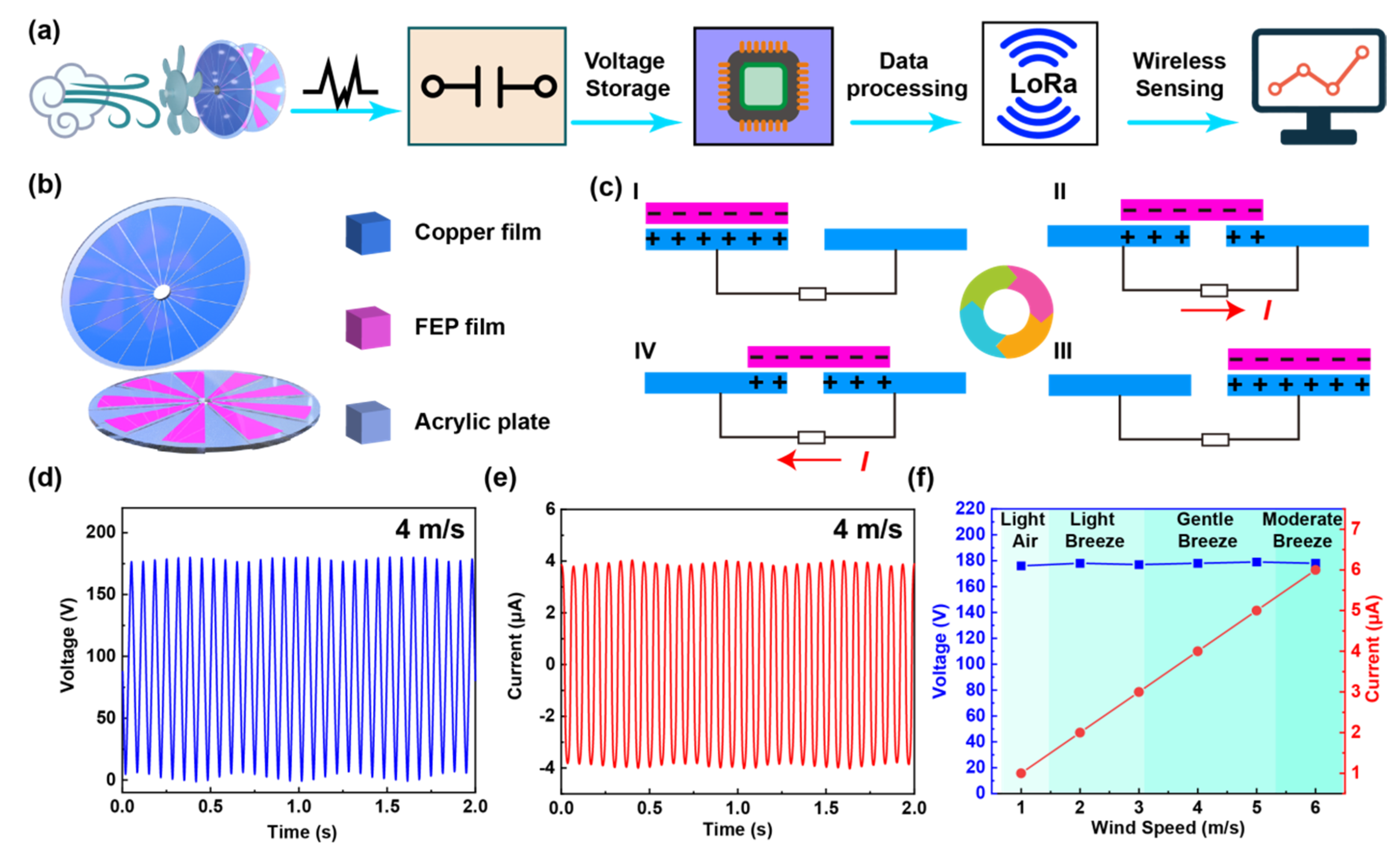
Figure 1. Overview of the wake-up system and the triboelectric nanogenerator (TENG). (a) Schematic diagrams showing the near-zero power triboelectric wake-up system (NP-TWS) for autonomous Beaufort scale of wind force monitoring. (b) Schematic diagram showing the structure of the TENG. (c) Working principle of the TENG. (d) The output voltage and (e) output current of TENG in moderate breeze. (f) The output peak-voltage and peak-current of TENG with the Beaufort scale of wind force at grades 1–4.
Nanoenergyadv 01 00006 g001
Figure 2. The wake-up circuit using TENG as a sensor. (a) The circuit schematic diagram of the wake-up circuit in standby mode. (b) The circuit schematic diagram of the wake-up circuit in active mode. (c) The voltage of the C1 with different capacitance in light air. (d) The voltage of C1 with different resistance in light air. (e) The response time of the wake-up circuit with different capacitance on the Beaufort scale of wind force at grades 1–4. (f) The voltage of C1 with different resistance on the Beaufort scale of wind force at grades 1–4.
Nanoenergyadv 01 00006 g002
Figure 3. The stage circuit (SC) and the system power consumption. (a) The circuit schematic diagram of SC in active mode. (b) The comparison voltage with the Beaufort scale of wind force at grades 1–4. (c) The power consumption of the wake-up system in standby mode and active mode.
Nanoenergyadv 01 00006 g003
Figure 4. Demonstration of Beaufort scale of wind force monitoring. (a) Sketch of the NP-TWS for Beaufort scale of wind force monitoring. (b) The photo of the TENG. (c) The photos of the wake-up circuit, microprogrammed control unit (MCU), LoRa transmitting module (LTM), and LoRa receiving module (BRM). (d) The comparison of voltage of the system in a simulated wind environment. (e) The power consumption of the NP-TWS and the received data of the terminal in a simulated wind environment.
Nanoenergyadv 01 00006 g004
Publisher’s Note: MDPI stays neutral with regard to jurisdictional claims in published maps and institutional affiliations.