Project Report

Comparing Suitability of Distillation and Membrane for Production of Heavy-Duty 5% Propane

by
Yousef Alqaheem
*,
Abdulaziz A. Alomair
and
Mohammad Alobaid
Petroleum Research Center, Kuwait Institute for Scientific Research, Safat 13109, Kuwait
*
Author to whom correspondence should be addressed.
Gases 2025, 5(4), 27; https://doi.org/10.3390/gases5040027
Submission received: 25 September 2025 / Revised: 19 November 2025 / Accepted: 20 November 2025 / Published: 24 November 2025

Abstract

The demand for heavy-duty 5% (HD5) propane is expected to increase in the future due to the use of the gas as a fuel for engines. A refinery produces HD10 propane, and it is looking to upgrade to HD5 propane using either the conventional process (distillation) or an energy-saving unit (membrane). This study compared the two technologies in terms of product quality and quantity using process simulation in UniSIM®. The software also provided the design parameters and power consumption for the two processes. The results show that the membrane was competitive with distillation and was capable of producing 96 mol% propane with a recovery of 99.3%. On the other hand, distillation achieved a maximum propane quality of 95 mol% with a recovery of 99.9%. Surprisingly, the energy consumption in the membrane was 669 kWh, which was higher than that of distillation (540 kWh) due to the requirement for a pre-heating step. Therefore, the technology should be selected based on either the quality or quantity of propane.

1. Introduction

Propane is an odorless gas that is mainly used as a fuel. Many industrial boilers and furnaces run on propane due to its high efficiency [1]. The gas is also used domestically for heating and cooking. Moreover, propane is used as a fuel for hot-air balloons and a propellant in aerosol sprays [2,3].
Propane is formed mainly from the separation of liquefied petroleum gas (LPG). This stream contains other hydrocarbons such as butane. LPG is produced from the processing of associated gas that emerge during oil production [4]. LPG is also produced from other refinery units such as crude distillation, hydrocracker, delayed coker, and fluid catalytic cracking (FCC) units [5]. Significant amounts of LPG are known to be produced by FCC compared to other units [6].
A refinery is looking to produce heavy-duty 5% (HD5) propane to meet the future market for using propane as a fuel. In developed countries such as the United States, HD5 propane is used in forklifts due to its high octane number, which gives higher power [7]. Currently, the refinery produces HD10 propane at the propylene recovery unit (PRU) after the fluid catalytic cracking (FCC) process. The conventional method to purify propane from propylene is distillation, but the process is costly [8]. The refinery is seeking alternative processes for propane/propylene separation, such as a membrane. It is reported that a membrane has lower capital investment with reduced energy consumption compared to distillation [9].
Facilitated transport membranes (FTMs) are one of the promising technologies for propane/propylene separation [10]. FTMs are easier to fabricate compared to other membrane materials [11]. Many FTM units have been installed in refineries, and FTMs have stable performance for long-term operation [12]. FTMs are based on a polymer with the addition of adsorption sites like silver. It was observed that silver acted as a carrier for propylene molecules and prevented propane from passing the membrane [13].
In this paper, the efficacy of distillation was compared with that of a membrane for upgrading propane using process simulation. The study was performed in Honeywell UniSIM® to determine the quality and quantity of propane from the two technologies. The simulation also provided the design parameters of the new distillation method and the membrane. Furthermore, energy consumption was also estimated. Such technical comparisons between the efficacy of distillation and a membrane for upgrading to HD5 propane are rarely reported in the literature.

2. Materials and Methods

The design and operating conditions of the refinery PRU were used to develop a case in UniSIM® R500 (2024). The case was solved using the reported reflux ratio (19.4) and propane production rate (10.3 m3 h−1). After that, an additional distillation column was added to PRU to determine the required number of stages in the new distillation tower to produce HD5 propane. This was achieved by increasing the number of stages in the new column from 25 to 175 stages. The new column was integrated within the column environment so that the case could still be solved by using the reflux ratio and propane production rate.
Next, a commercial membrane for propane/propylene separation was selected, and the performance data is given in Table 1. The membrane is based on a fluoropolymer containing silver. The membrane is selective to propylene with a permeation of 150 GPU. The reported propylene-to-propane selectivity is 30.
UniSIM® does not have a ready-to-use membrane unit, so the system was manually created using a component splitter, adjust functions, and a spreadsheet. The membrane process flow is given in Figure 1. Mass balance equations were added to the spreadsheet. Numerical methods are needed to solve the system due to the non-linear equations. Simply, the membrane was solved by guessing the permeate cuts and comparing them with the calculated values based on the permeance data. As a starting point, the propylene permeate cut was set to 0.5, and the corresponding propane permeate cut was calculated from propylene-to-propane selectivity, which gives 0.016. The adjust functions then changed the initial guesses until the error between the guessed and calculated values were less than 0.0003. More details on solving the developed membrane model are described elsewhere [15].
Table 2 shows the operating conditions of the membrane system. The membrane area was changed from 500 to 5000 m3, and the propane quality and quantity were observed. The pressure ratio was five, meaning that the permeate stream (enriched propylene) had five-times lower pressure compared to the feed pressure applied to the membrane.

3. Results and Discussion

Propylene Recovery Unit (PRU): The current PRU process was built in UniSIM®, and the solved flow sheet is presented in Figure 2. Feed composed of 25 mol% propane and 75 mol% propylene enters the distillation unit at 26 bar and 48 °C with a flow rate of 37 m3 h−1. The column consists of 185 trays with a tray efficiency of 90%. The tower has a condenser at the top and a reboiler at the bottom. This design is widely used in the industry. The flow sheet was converged by fixing the reflux ratio at 19.4 and the propane draw rate at 10.3 m3 h−1. PRU produced two streams: top propylene with a quality of 99.4 mol% and bottom propane with purity of 93.4 mol%. The tower consumed 26.4 MW for the reboiler and 26.6 MW for the condenser.
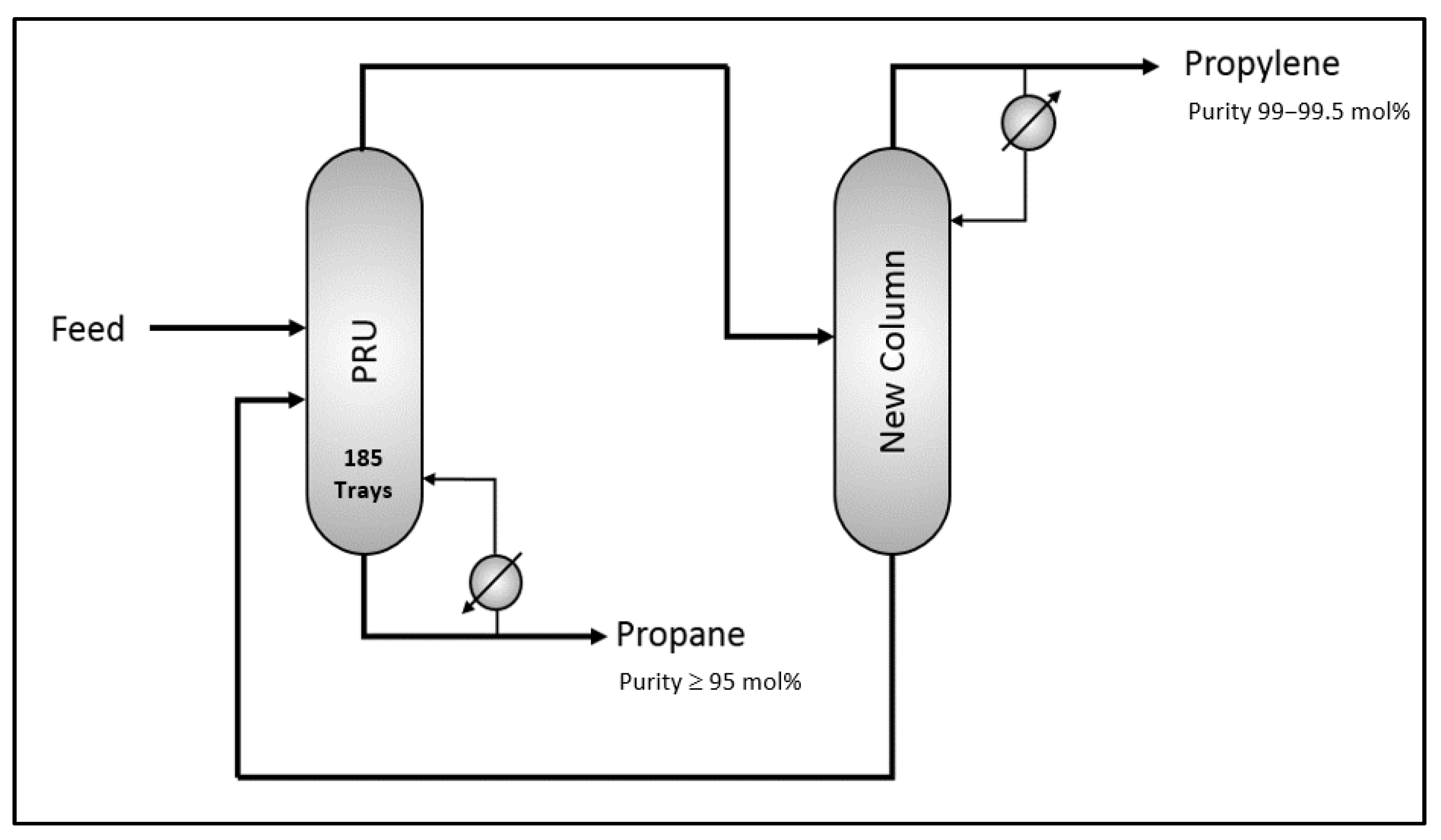
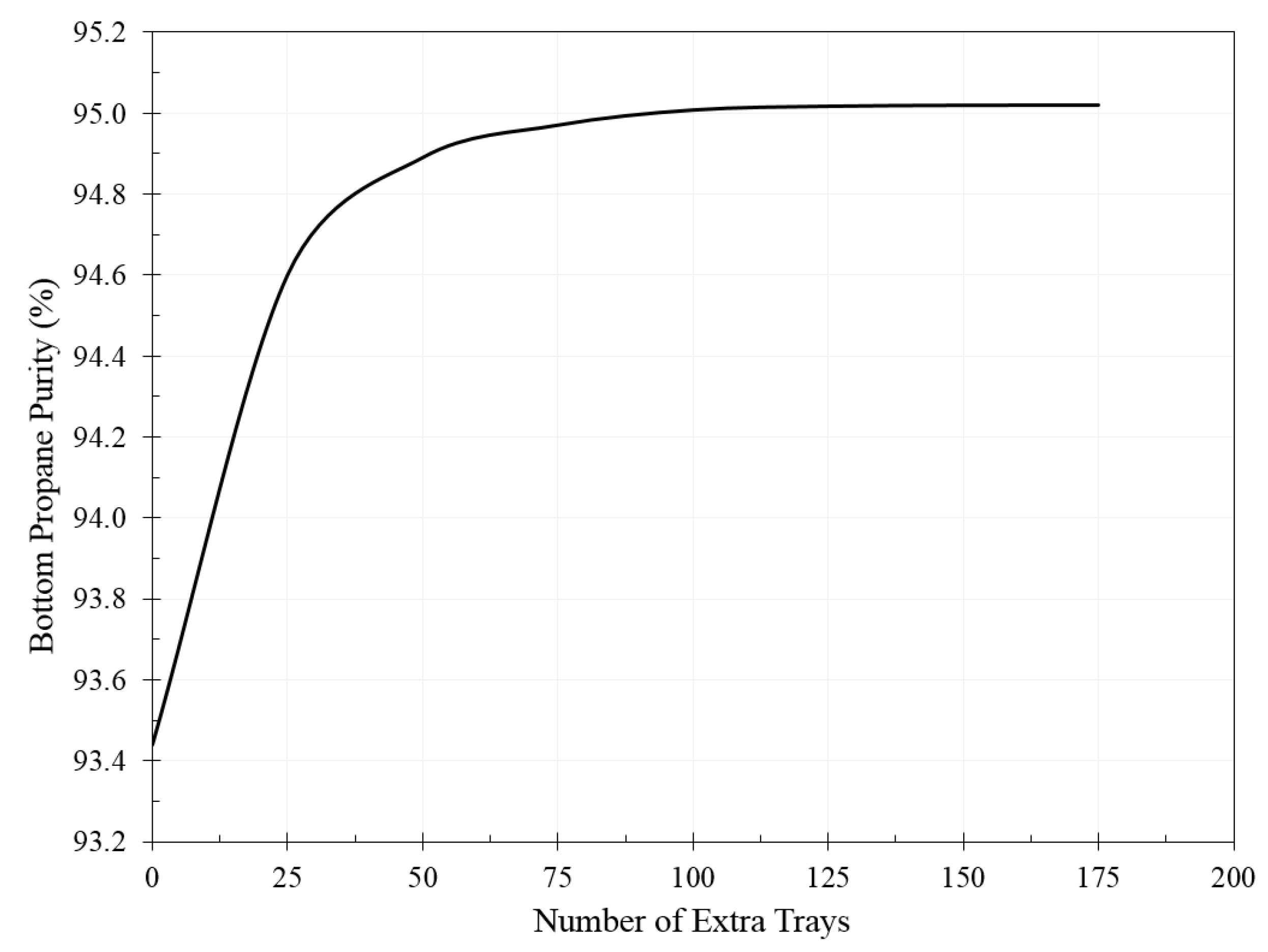
New Distillation Column: After creating the PRU case in UniSIM®, an additional distillation column was added to PRU to enhance propane quality to ≥95 mol%. The bottom propane from PRU was sent to the new tower. The second tower works in parallel with PRU distillation, in which the bottom product from the second tower is recycled back to PRU, as shown in Figure 3. Furthermore, the condenser was removed from PRU and moved to the second tower for better energy optimization. The extra number of stages was plotted against the produced propane quality, as demonstrated in Figure 4. It was found that the propane quality was 95 mol% using 100 extra trays, and adding more trays did not increase propane quality at the current production rate of 10.3 m3 h−1.
The additional column further improved propane recovery from 98.3 to 99.9%. Propylene purity was also enhanced from 99.4 to 99.9%. It should be noted that the energy consumption increased by 540 kWh; the reboiler consumed 250 kWh more power, while the condenser energy increased by 290 kWh.
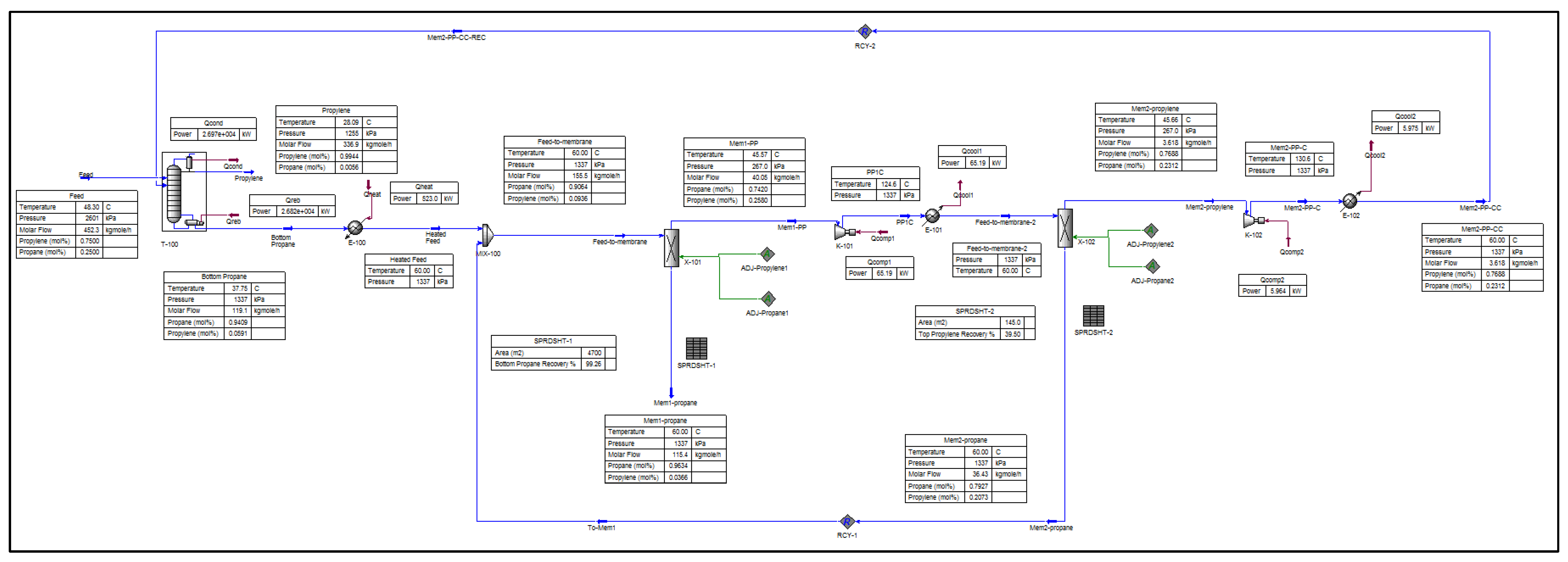
Membrane Unit: Initially, a single-stage membrane was used to study the effect of membrane area on the quality and quantity of the produced propane, as presented in Figure 5. The membrane area against propane quality and quantity is plotted in Figure 6. Unlike distillation, the membrane achieved a higher propane quality than 95 mol%. However, there is a tradeoff between propane quality and quantity. For example, at an area of 2000 m2, the membrane produced 96 mol% propane, but the recovery was only 88%. In distillation, a maximum quality of 95 mol% propane was produced but with an outstanding recovery of 99.9%. To overcome this issue, a two-stage membrane system is needed to improve propane quantity. The two-stage system consists of two membranes with a recycling stream from the second membrane back to the first unit. The solved case is given in Figure 7, and the recovery considerably increased from 88 to 99.3% while maintaining propane quality at 96 mol%. Nevertheless, the membrane produced a permeate stream containing only 80 mol% propylene, known as refinery-grade propylene (RGP). This stream has a lower value compared to polymer-grade propylene (>99 mol%). To make use of this stream, distillation–membrane integration was proposed by recycling the RGP stream back to the PRU, as shown in Figure 8. After this, the PRU with the membrane produced only two streams: 99.4 mol% propylene and 96 mol% propane.
As shown in Figure 8, the membrane system consists of many pieces of equipment that consume energy, such as compressors, coolers, and a pre-heater. The compressors are needed to provide the driving force for mass transport, and the required power is 75 kWh. The coolers are used after the compressors to cool down the streams, as the compression will cause heat generation. The coolers need another 71 kWh. The pre-heating step is essential because the bottom propane from the PRU is in liquid form, and it cannot enter the membrane. The stream should be transformed to a gaseous state by heating it from 38 to 60 °C. This will demand an excessive amount of energy of 523 kWh. Thus, the total energy requirement for the membrane system is 669 kWh, which is higher than the 540 kWh of energy consumed by distillation. However, the refinery has no issues in providing heat for the membrane process. It should be noted that the total required membrane area is 4845 m2.
At this stage, the membrane system can compete technically with distillation, and Table 3 shows the difference in performance between the membrane and distillation for upgrading to HD5 propane. To decide which technology is better, economic analysis is needed. The economic assessment will be based on the capital expenditure (CAPEX) and the annual operating expenses (OPEX). CAPEX is related to the purchase cost of the equipment, while OPEX includes maintenance and utility bills. This analysis will be carried out in a future work.
It is worth noting that the results of this study depend on the specific operating conditions of the refinery. The outcome also depends on the type of distillation tower and the membrane material. Any changes to these input data may significantly affect the simulation results.

4. Conclusions

A refinery is producing HD10 propane and is looking to upgrade to HD5 to meet future market demands. Two technologies for purifying propane were considered in this study: distillation and a membrane. Process simulation by UniSIM® was performed to evaluate the two technologies in terms of propane quality and quantity along with energy consumption. The results show that distillation achieved a maximum propane concentration of 95 mol%, while the membrane reached a higher concentration of 96%. On the other hand, distillation resulted in slightly better recovery (99.9%) compared to the membrane (99.3%). The energy consumption by distillation was 540 kWh, while the membrane consumed more power (669 kWh), which was related to the required pre-heating step. It was concluded that both technologies are sufficient for upgrading propane, and the technology should be selected based on either propane quality or quantity. Moreover, an economic assessment will provide a critical analysis for unit selection by comparing the capital investment and the annual operating cost.

Author Contributions

Conceptualization, Y.A.; Methodology Y.A.; software, Y.A.; Validation A.A.A.; Formal analysis, M.A.; writing original draft preparation, Y.A.; funding acquisition, Y.A. All authors have read and agreed to the published version of the manuscript.

Funding

This project was funded by a refinery under the code PF118C.

Data Availability Statement

The data presented in this study are available on request from the corresponding author due to confidentiality.

Conflicts of Interest

The authors declare no conflicts of interest.

References

  1. Heselton, K. Boiler Operator’s Handbook; Lulu: Morrisville, NC, USA, 2015. [Google Scholar]
  2. Balloon Flying Handbook; U.S. Department of Transportation: Washington, DC, USA, 2007.
  3. Safetyline; United States Naval Safety Center: Norfolk, VA, USA, 1991.
  4. Mokhatab, S.; Poe, W.; Mak, J. Handbook of Natural Gas Transmission and Processing: Principles and Practices; Elsevier Science: Amsterdam, The Netherlands, 2015. [Google Scholar]
  5. Fahim, M.; Al-Sahhaf, T.; Elkilani, A. Fundamentals of Petroleum Refining; Elsevier Science: Amsterdam, The Netherlands, 2009. [Google Scholar]
  6. Sadeghbeigi, R. Fluid Catalytic Cracking Handbook: An Expert Guide to the Practical Operation, Design, and Optimization of FCC Units; Elsevier Science: Amsterdam, The Netherlands, 2000. [Google Scholar]
  7. Folkson, R.; Sapsford, S. Alternative Fuels and Advanced Vehicle Technologies for Improved Environmental Performance: Towards Zero Carbon Transportation; Woodhead Publishing: Cambridge, UK, 2022. [Google Scholar]
  8. Abbasi, S.; Khosravi-Nikou, M.; Shariati, A. Removal of propylene from fuel-grade propane. Sep. Purif. Rev. 2007, 33, 157–182. [Google Scholar]
  9. Yamaki, T.; Thuy, N.; Hara, N.; Taniguchi, S.; Kataoka, S. Design and evaluation of two-stage membrane-separation processes for propylene–propane mixtures. Membranes 2022, 12, 163. [Google Scholar] [CrossRef] [PubMed]
  10. Guo, M.; Kanezashi, M. Recent progress in a membrane-based technique for propylene/propane separation. Membranes 2021, 11, 310. [Google Scholar] [CrossRef] [PubMed]
  11. Su, Y.; Cong, S.; Shan, M.; Zhang, Y. Enhanced propylene/propane separation in facilitated transport membranes containing multisilver complex. AIChE J. 2022, 68, e17410. [Google Scholar] [CrossRef]
  12. Zhang, J.; Shahidi, K.; Sekhon, G.; Hudson, A.; Hatahet, M.; Salih, F.; Wang, X. Permylene™ membrane technology: An efficient approach to separate propylene from propane. J. Membr. Sci. 2024, 690, 122204. [Google Scholar] [CrossRef]
  13. Kasahara, S.; Kamio, E.; Minami, R.; Matsuyama, H. A facilitated transport ion-gel membrane for propylene/propane separation using silver ion as a carrier. J. Membr. Sci. 2013, 431, 121–130. [Google Scholar] [CrossRef]
  14. CMS. OptipermTM Membrane Demonstrates Stable Performance in Pilot Study of HD5 Propane Production. 2017. Available online: https://compactmembrane.com/wp-content/uploads/2019/10/DCRC-Pilot-Study-White-Paper.pdf (accessed on 1 April 2024).
  15. Alqaheem, Y. Accuracy of Mathematical Models and Process Simulators for Predicting the Performance of Gas-Separation Membranes. Eng 2024, 5, 3137–3147. [Google Scholar] [CrossRef]
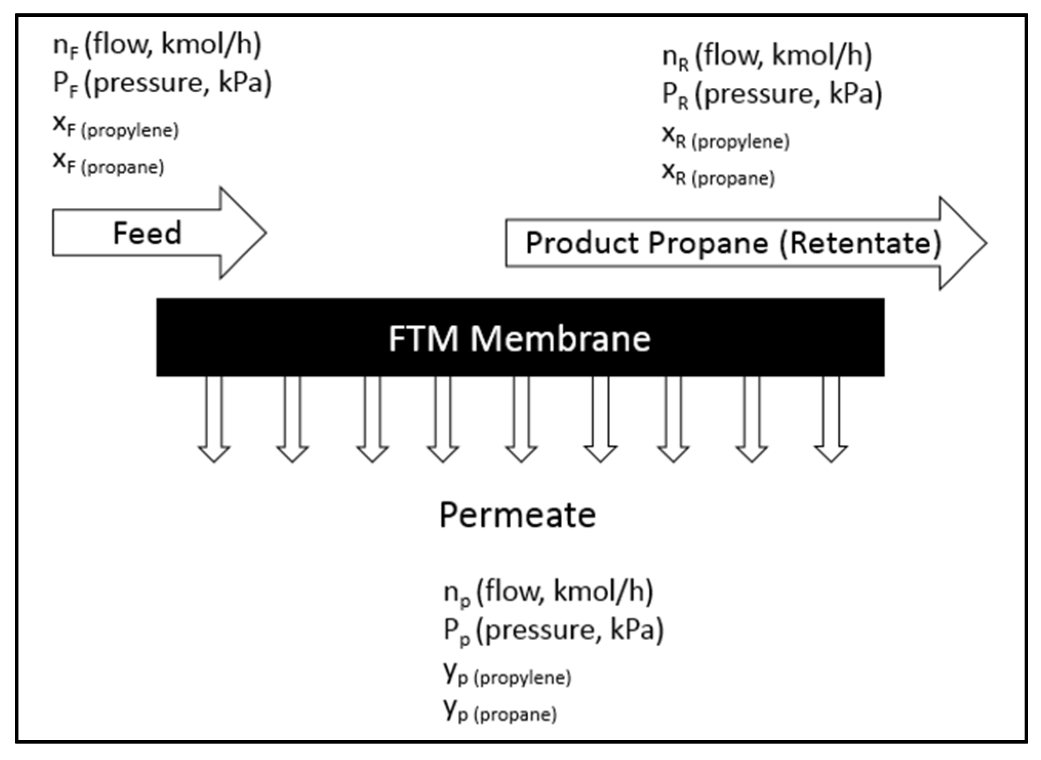
Figure 1. Membrane process flow for propane/propylene separation.
Gases 05 00027 g001
Figure 2. Solved case in UniSIM® to simulate current PRU.
Gases 05 00027 g002
Figure 3. Use of an additional distillation column to improve propane quality in PRU.
Gases 05 00027 g003
Figure 4. Number of stages in the new distillation column and the quality of produced propane.
Gases 05 00027 g004
Figure 5. Use of a membrane unit to upgrade PRU bottom propane.
Gases 05 00027 g005
Figure 6. Performance of a single-stage membrane for upgrading PRU propane.
Gases 05 00027 g006
Figure 7. Solved UniSIM® case for upgrading bottom propane from PRU using a two-stage membrane system to produce 96 mol% propane with 99.3% recovery.
Gases 05 00027 g007
Figure 8. PRU–membrane integration for producing 96 mol% propane with 99.3% recovery.
Gases 05 00027 g008
Table 1. Properties of a commercial membrane for propane/propylene separation [14].
PropertyValue
Propylene permeance150 GPU
Propylene/propane selectivity (α)30
Maximum operating temperature/pressure70 °C/18 bar
Table 2. Operating conditions of the membrane system for propane/propylene separation at PRU.
PropertyValue
Distillation bottom propane pressure13.3 bar
Distillation bottom propane temperature37.7 °C
Distillation bottom propane flow rate10.3 m3 h−1
Membrane retentate pressure13.3 bar
Membrane permeate pressure2.7 bar
Membrane area500 to 5000 m2
Table 3. Product quality and quantity of distillation and membrane for upgrading PRU propane to HD5 along with energy consumption.
PropertyPRUMembraneDistillation
Propane purity (mol%)93.496.395.0
Propane recovery (%)98.399.399.9
Propylene purity (mol%)99.499.499.9
Propylene recovery (%)97.798.898.2
Energy consumption (kWh)669540
Disclaimer/Publisher’s Note: The statements, opinions and data contained in all publications are solely those of the individual author(s) and contributor(s) and not of MDPI and/or the editor(s). MDPI and/or the editor(s) disclaim responsibility for any injury to people or property resulting from any ideas, methods, instructions or products referred to in the content.