Proceeding Paper

Coupling Computational Fluid Dynamics and Artificial Intelligence for Sustainable Urban Water Management and Treatment †

1
Department of Civil and Environmental Engineering, University of Tennessee, Knoxville, TN 37996, USA
2
Department of Civil Engineering and Construction, Bradley University, Peoria, IL 61625, USA
3
Engineering School of Sustainable Infrastructure and Environment, University of Florida, Gainesville, FL 32611, USA
*
Author to whom correspondence should be addressed.
Presented at the International Conference EWaS5, Naples, Italy, 12–15 July 2022.
Keynote Speaker.
Environ. Sci. Proc. 2022, 21(1), 87; https://doi.org/10.3390/environsciproc2022021087
Published: 29 January 2023

Abstract

:
Water treatment systems have been implemented by urbanizing societies for millennia to facilitate water management goals. Common models of surface overflow rate (SOR), plug flow reactor (PFR), and continuously stirred-tank reactor (CSTR) were developed through conceptual, empirical, and analytical tools; implemented based on idealized hydrodynamics and geometrics. More recently, computational fluid dynamics (CFD) and artificial intelligence (AI), from evolutionary optimization to machine learning (ML) methods, have been introduced. AI methods can be effectively coupled with CFD simulations to optimize water treatment. In this study, CFD coupled with physical models and selected ML and optimization tools, including DeepXtorm, are examined with respect to design, treatment analysis, and retrofits, providing significant economic and treatment benefits.

1. Introduction

Of the three primary urban water components, potable-, waste-, and stormwater (urban drainage herein), this paper focuses on urban drainage treatment, specifically clarification of particulate matter (PM), as the primary vehicle and substrate for partitioning/distribution of chemicals and pathogens. The fundamental principles elucidated herein translate to potable- and wastewater control and management as well as for combined sewer overflows. Urban drainage generated from storm events transports PM, chemicals, and pathogens to receiving waters, impacting aqueous chemistry acutely and chronically with consequences for public health (e.g., harmful algal blooms, HAB). For a half-century, clarifier systems, specifically urban drainage basins, have been a common unit operation (UO) with unit process (UP) functionality, deployed in built environments for hydraulic/volumetric management and clarification. Urban drainage clarification basins in the United States (US) now exceed 10 million. These clarifiers intercept approximately 25% of the runoff in the US. Despite clarifier ubiquity, fundamental PM and PM-associated chemical transport and fate processes are poorly understood. This knowledge gap is a result of the complexity of nonlinear interaction and multiphase coupling of turbulence, partitioning/distribution, and heterodisperse PM. Irrespective of surface overflow rate (SOR) [1], design and regulatory guidance for clarifiers have historically employed presumptive criteria based on mean residence time (RT) [2,3,4,5]. Decades of such practice have led to an impairment designation for most clarifiers that does not meet load reduction requirements. More importantly, clarifiers do not meet intended functionality, with discharge of PM, chemicals, and pathogens harmful to humans and the urban water cycle. In most cases, geometric expansion of clarifiers as open basins, tanks, or tunnels is not viable due to infrastructure constraints, an even greater constraint in the built environs of Europe. There is a critical need to supplant existing tools with higher-fidelity physics-based simulation tools to inform (1) design/regulatory guidance, (2) basin functionality, and (3) intra-basin retrofits, for example, with internal baffles to train clarifier hydrodynamics. This paper illustrates the combination of computational fluid dynamics (CFD) and physical modeling of fundamental transport/fate of PM, noting that the extension to PM-partitioned chemicals only requires partitioning/distribution data. Herein, CFD is integrated with machine learning (ML), providing robust, effective, and efficient planning and retrofits. The main objectives are (i) to review current empirical and lumped analytical models (RT, SOR, CSTR, PFR) for clarification basins, (ii) illustrate results of clarifier turbulence transport and PM fate, (iii) illustrate CFD for basin transport/fate simulation, (iv) enhance functionality and economy of clarification basin geometrics and intra-basin retrofits with ML, and (v) couple ML methods with CFD to develop a CFD-ML augmented basin analysis and retrofit tool, DeepXtorm, with extensibility to any management or treatment system for urban waters.

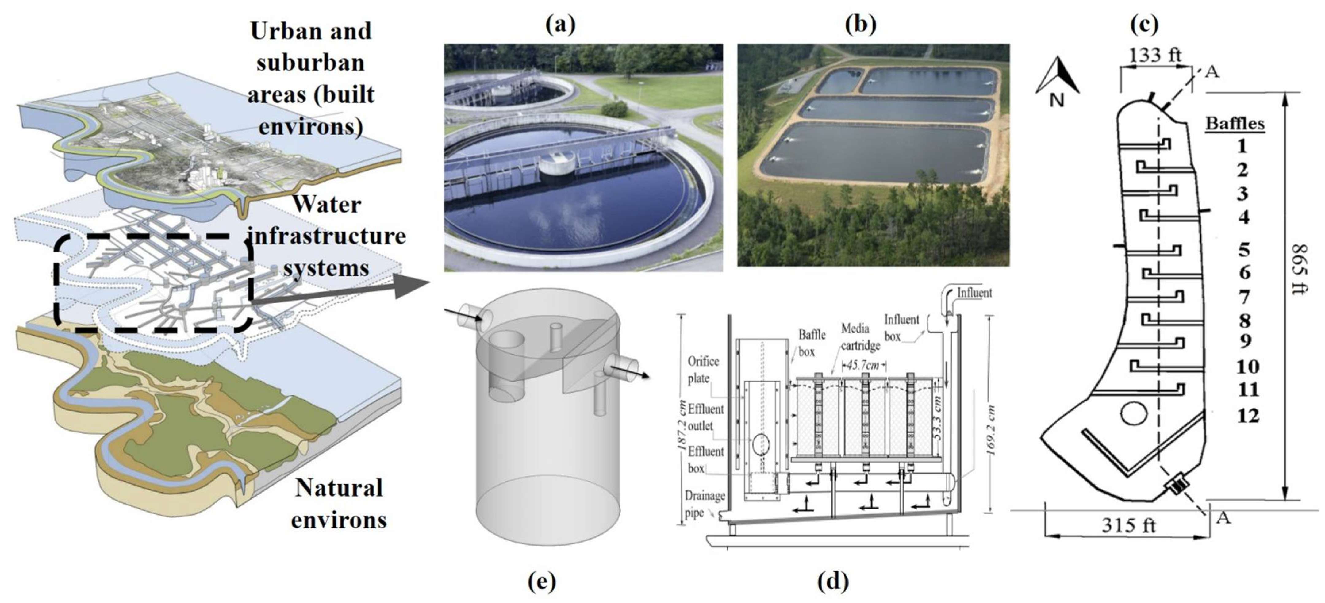
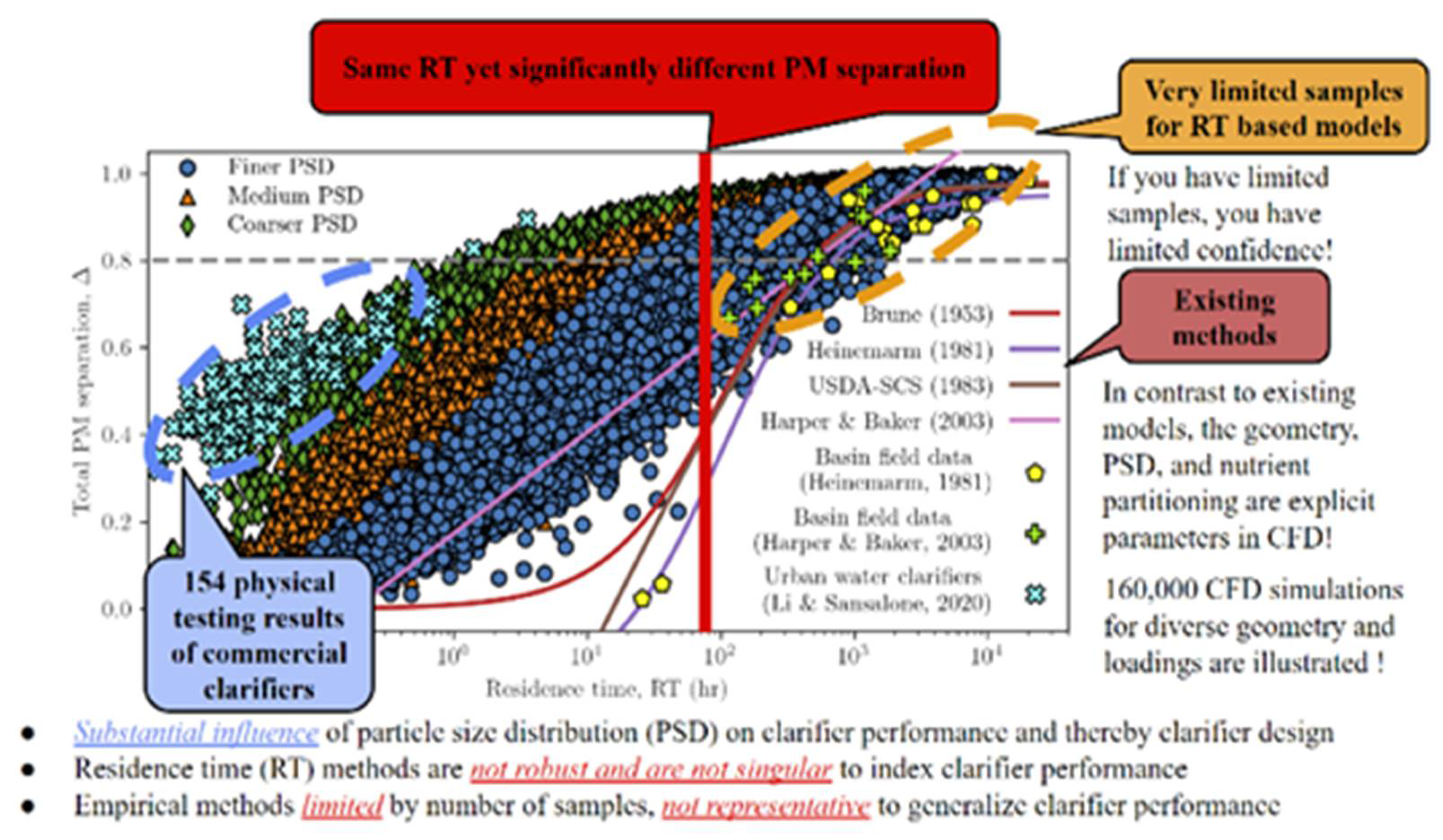
2. Clarification of Particulate Matter (PM) for Urban Drainage Treatment

Clarification as a UO to separate PM and PM-partitioned constituents by gravitational forces has been employed in built environments for thousands of years to facilitate societal needs for water supply, treated discharge, or reuse. Figure 1 illustrates the overlay between the built environments, water infrastructure clarification systems, and the natural environments, identifying common types of clarification systems. Historically, and currently, clarification is an essential mechanism for management of PM, PM-partitioned chemicals, and PM-partitioned pathogens. PM, while not an emerging contaminant, is the dominant, labile, and high-surface-area substrate for partitioning and transport of emerging or known chemicals and pathogens. Knowledge of the constitutive properties of PM and partitioning to/from PM are critical and necessary when evaluating clarification. For all of these water cycle components, clarifiers are a critical UO for separating PM in preliminary, primary, and secondary treatment train unit operations and processes. While PM separation in volumetric units such as clarification basins is the focus, filtration is also a UO for clarification of PM (albeit a secondary UO following primary clarification). Similarly, with respect to activated sludge or membranes, clarification systems are still required upstream of such units.
While the necessity of clarification in wastewater treatment has been recognized and implemented for over a century, the need for clarification as an engineered UO for urban drainage is a much more recent focus. On an annual basis for a municipality, the episodic and unsteady flow volume and the loads of PM, metals, and chemical oxygen demand (COD) in urban drainage flow equals or exceed loads delivered by quasi-steady and diurnal wastewater (as dry weather flows) [6]. For urban drainage, clarification units or systems can range from hydrodynamic separator (HS) units as a preliminary UO for separation of only debris/detritus/gross solids to a broad classification of primary/secondary clarification systems that are ubiquitous for management of water cycle components. These primary/secondary treatment systems include above-ground basins (as detention or retention), below-ground tanks or tunnel systems, or online and offline volumetric storage units. These systems provide multiple functions that integrate equalization as a hydraulic/volumetric UO with physical primary treatment. As a function of spatial constraints, these systems are implementable in a wide range of conditions in built environments and across urban, suburban, and rural land uses. Historically and currently, clarification basins are a lower technology UO solution that can be readily and economically implemented in developing communities, although in built environments, current design practices according to residence time (RT)-based presumptive criteria of treatment results in significant lost opportunity land costs and economic burden [7].

3. Common Models of Urban Drainage Clarification Units

Investigating clarification dynamics and examining models for clarification UOs subject to complex hydrodynamics and geometry contribute to the goal of more sustainable water systems and management thereof. Clarification models currently range from the increasing implementation of CFD to the much more commonly deployed analytical or empirical models developed prior to digital computers. Such analytical and empirical models for clarification (in volumetric units such as basins or tanks) were developed by Hazen (1904) [1] and a competing model by Camp (1936) [8], among others since Hazen’s seminal 1904 publication, “On Sedimentation”, based on surface overflow rate (SOR). In these early studies, the analytical models (also known as conceptual or semi-empirical models) of SOR, plug flow reactor (PFR), and continuously stirred-tank reactor (CSTR), were developed through conceptualized geometry of clarification systems (e.g., rectangular, prismatic) and idealized hydrodynamic conditions (i.e., plug flow or well-mixed condition). Subsequently, a tanks-in-series method was introduced to generalize non-idealized clarification, in which the non-idealized clarification is characterized as a transition between two hypothesized limiting conditions of PFR and CSTR, noting that a PFR or CSTR-assumed conditions have recently been shown not to be limiting [9]. With the development of digital computers, algorithms of clarification have progressed in the last 50 years. While clarification models have evolved, these models are most commonly represented as lumped (or partially lumped) process-based simulations (i.e., dynamic models) [10] that do not resolve the hydrodynamic complexity and complex geometry of clarification systems. Figure 2 presents the results of SOR, CSTR, and PFR models to full-scale physical modeling data (the plotted symbols) and that of a plain cylindrical tank (SAFL-CT) in plot (a), illustrating a range of commercial clarifier systems, some of which are shown in plot (b), and the turbulent flow configuration and vortical structures generated within the simple geometry of a plain cylindrical tank clarification system as modeled from large-eddy (LES) simulation and shown in plot (c). While SOR reasonably represented the physical model data from these 17 different commercial clarification systems, albeit distinctly below the mean trend line (the solid thick red curve), the PFR and CSTR models do not represent the physical modeling data. For PM clarification, the plain cylindrical tank configuration (SAFL-CT) outperformed most of the less economical commercial clarifier systems across the characteristic velocity scale (SOR). Irrespective of the common model chosen, these common models are unable to elucidate the role of turbulence and illustrate the turbulent structure within these systems.

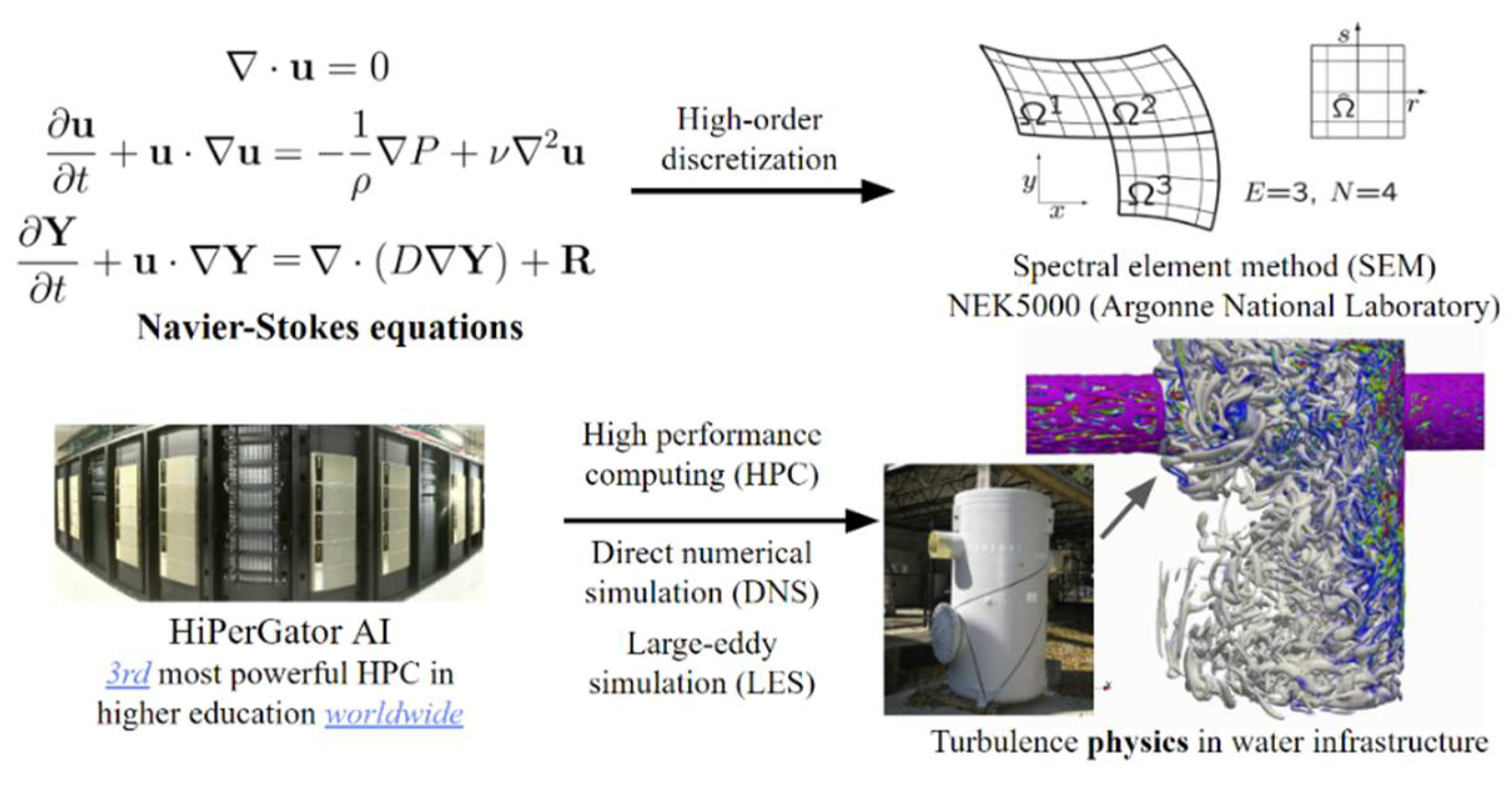
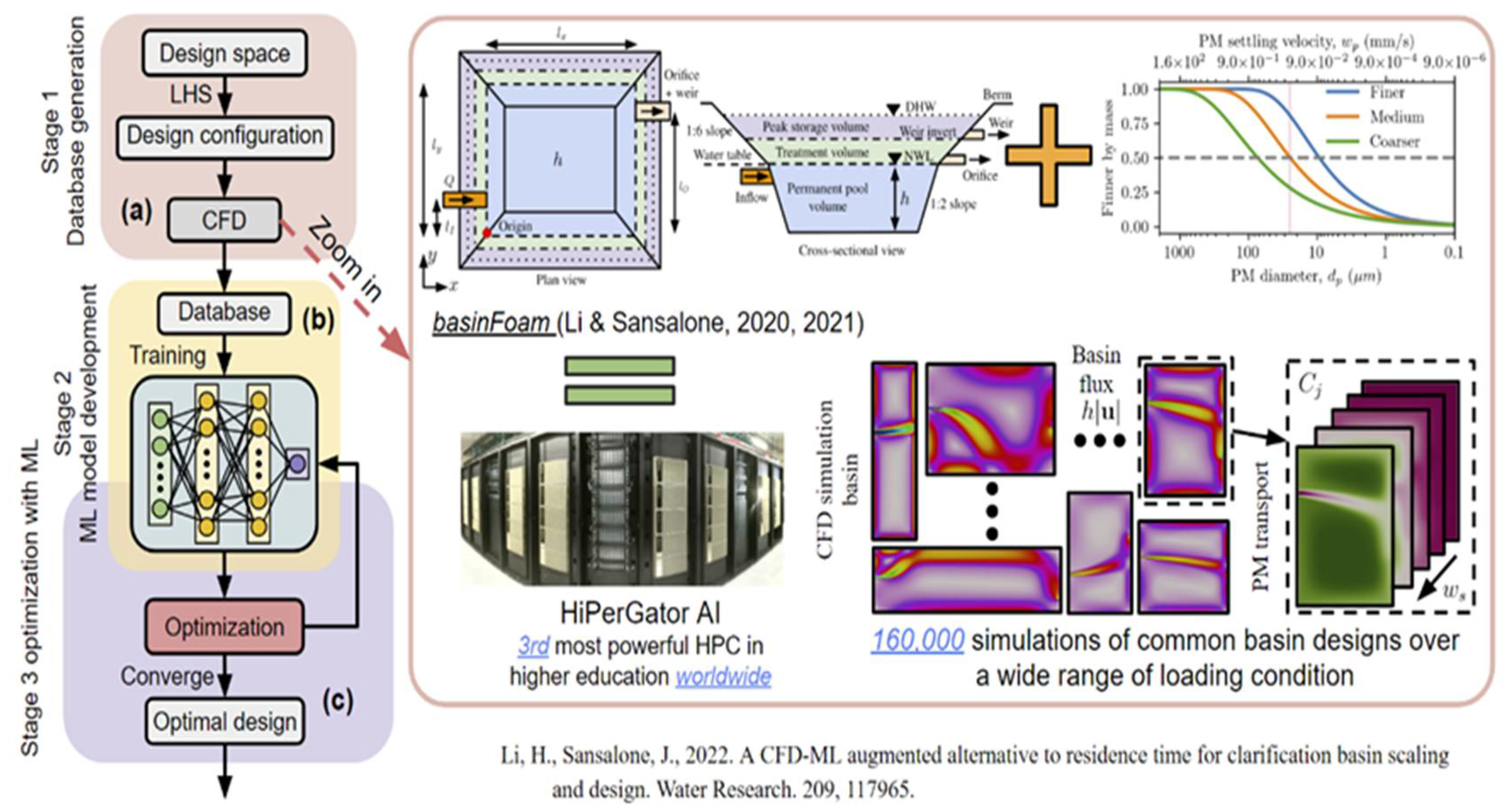
4. CFD and ML as an Artificial Intelligence (AI) Method

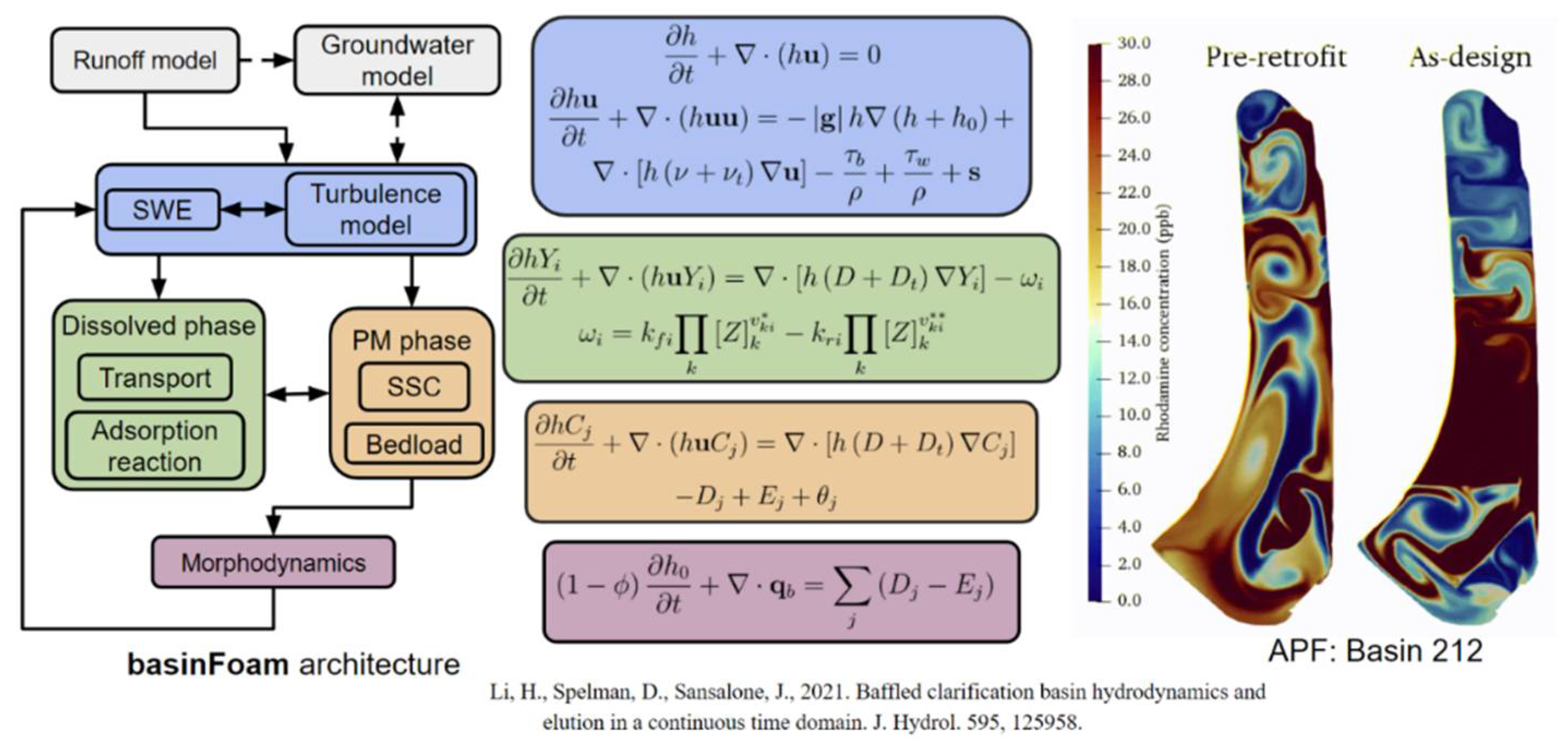
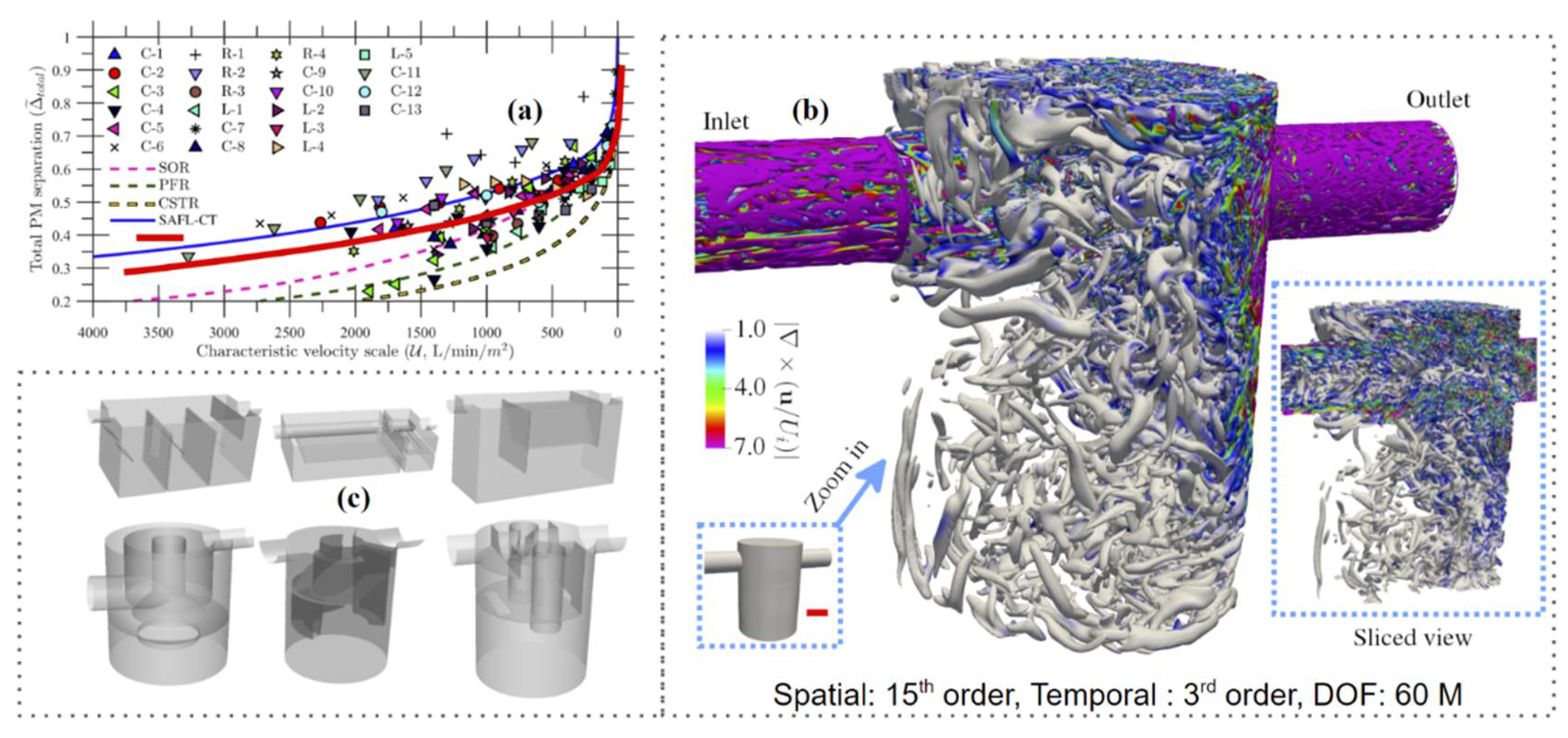
4.1. CFD for Clarification

Much more recently, models have evolved towards incorporating hydrodynamic-resolving CFD-based simulations. With respect to the analytical models developed within the last century, Reynolds-Averaged Navier–Stokes (RANS)-based CFD models provides improved predictive capabilities and the potential for further development [11]. Advancements with respect to CFD and turbulence have also improved the accuracy of RANS-based models through the use of high-fidelity simulation methods of LES, as shown in Figure 3, and direct numerical simulation (DNS) [11,12,13,14]. For urban water systems including basins, a range of CFD tools for basin clarification simulation have been developed such as the shallow water equation (SWE) [15], RANS equations [16], and LES [13].
When examining CFD as a tool for water management, perspective is important. Despite significant advancement with CFD methods, resolving turbulence with such methods and facilities such as the HPC, the current state of clarification system design, management, and regulation adopt models of PFR and CSTR despite the inability of such models to reproduce physical modeling data as shown in Figure 2a. As an example of such an implementation, modeling of the rainfall–runoff process in the urban water cycle through a model such as the Storm Water Management Model (SWMM), which is a common, comprehensive, and well-developed analysis tool, allows implementation of these these analytical models (as lumped system models) [10]. Implementation of, and adherence to, these analytical models (and their dynamic variants) for clarification can also be widely found in the recent literature, and it demonstrates a level of predictive capability subject to specific geometric/hydraulic/granulometric conditions and chemical partitioning, in particular for low Hazen numbers (dimensionless settling velocities) [17] and for coarser particle size distributions (PSDs) [18,19,20,21]. In contrast to such conditions for application of these analytical models, multiphase turbulent flow [11,12,13,14,17] and RANS-based CFD clarification modeling illustrate the significant role and impact of complex system hydrodynamics on PM and pathogen transport, mixing, chemical partitioning to/from PM, and treatment efficacy. Such models need to be tested for clarification systems over a range of scales, for actual (not idealized) geometries and for complex and unsteady hydrodynamic conditions and loadings. While geometrics in a wastewater treatment plant (WWTP) clarifier are reasonably approximated, the geometrics of real urban drainage systems are quite complex, as are the turbulence structures and their temporal variability. In Figure 4, the depth-averaged Navier–Stokes equation in the framework of the shallow water equation (SWE) is illustrated for a typical above-grade urban drainage clarifier, subject to wet weather flow hydrodynamics, before retrofitting and after retrofitting with permeable gabion baffles [15]. There needs to be a clear demonstration of the applicability and the limits or boundaries of generality for such analytical/empirical models; otherwise, clarification system design and regulation with such models [5] will misrepresent treatment behavior and design/regulation will be guided by methods that are not representative and can be highly uneconomical for a given level of treatment performance [7,9,17].

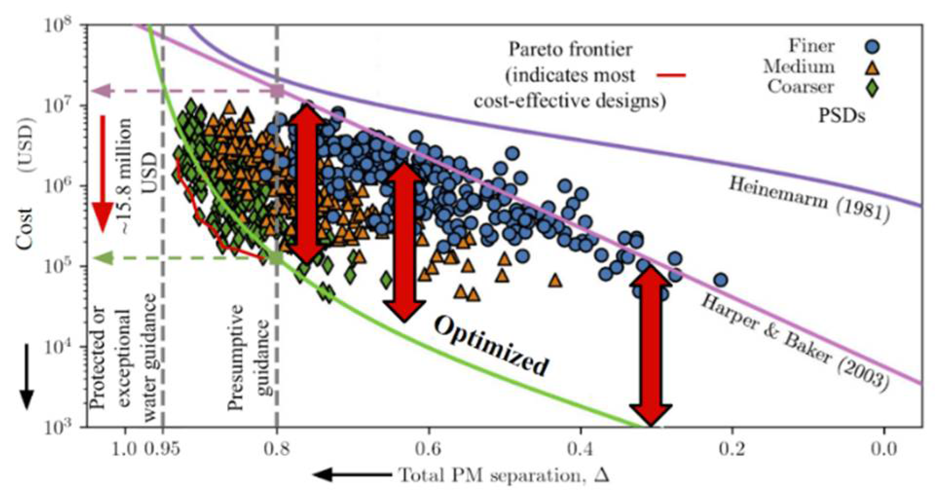
4.2. Machine Learning (ML)

Despite progress since the development and deployment of CFD, decades of regulatory, design, and management guidance for clarification are still commonly implemented based on empirical techniques and lumped indices introduced through the concept of RT by Brune (1953) [2]. Specifically, presumptive criteria based on RT (or hydraulic RT, HRT) to achieve a level of PM separation, for example, 80% of nutrients, are still widely adopted. The basis for RT from first principles to scale basin clarification is unclear, not robust and not economical, although it is worth noting that SOR does have a physical basis and can be related to the concept of a dimensionless settling velocity (Hazen number). Recent research has shown that RT cannot be used to scale clarifier basin performance over a wide range of system geometrics, PM granulometry, and loadings [7]. The cost of a single basin can range from hundreds of thousands to tens of millions United States Dollars (USD) as a result of current RT-based criteria [7,9,14]. There is a need for methods to leverage robust CFD capability yet provide a more user-friendly clarifier design, analysis, and retrofit experience.
When coupled with CFD, AI methods such as ML (CFD-ML) provide a potential solution for the more widespread adoption of CFD and a tool to optimize the performance of urban water systems such as clarifiers or optimize the economy of such systems at a given level of performance. This framework is shown in Figure 5. ML methods provide a spectrum of techniques to analyze data, model results and information, as well as identify patterns from the data or model results. For example, artificial neural networks (ANN) as one ML model are able to learn the multidimensional and nonlinear correlations between input features and output labels from data or model results, as supervised learning. With such functionality, analogous ML models can be created to approximate the mapping relation between clarifier basin geometric parameters (features) and basin clarification or water chemistry functionality (labels), for example, based on the higher-fidelity CFD simulations of PM, PM-partitioned constituents, or solute transport and fate.
In comparison to empirical or lumped analytical models (RT, SOR, PFR, CSTR), such trained ML models replicate the dependence of PM (PSD and PM density) and solute transport/fate to the detailed system geometrics, loading condition, hydrodynamics, and constitutive load properties. In contrast to LES, trained ML models reduce CFD computation time and facilitate a simple and efficient examination of basin geometrics, retrofit of impaired basins, and regulation for practical application that is predicated on existing CFD model outputs. Such a combination of CFD and ML enhances and extends the existing knowledge base and methods for urban water system design, analysis, retrofit, and regulation. A new approach that hybridizes CFD and ML models facilitates robust, simple, and economical clarifier analysis, and geometric design with capability of retrofit design [7]. The framework for clarifier design and optimization is shown in Figure 5. A critical component of this framework is high-performance computing (HPC) to facilitate CFD simulations.
A set of results from implementation of the CFD modeling component of this framework for clarifiers of diverse geometries and loadings are illustrated in Figure 6. In this figure, historical RT methods and the current regulatory guidance using RT developed through Harper and Baker (2003) [5] are overlayed as curves on plot of total PM (the entire particle size distribution, PSD, not a PSD fraction such as total suspended solids, TSS) separation as a function of RT.
Focusing on Harper and Baker (2003) [5], this RT model is based on and extrapolated from only 13 field data points. The RT method [5] is agnostic to hydrodynamics, partitioning, geometry, and PM constitutive properties such as PSD. For example, subject to loadings of different PSDs at the same RT, total PM separation ranges from 40 to 90%. Furthermore, full-scale physical testing of commercial clarifiers of lower RT also yields results distinctly different from the RT method [5,17]. As a result, clarifiers underperform and are 10 to 100× more costly than those optimized with CFD-ML.
While the ability to separate PM (nutrients, metals, organics, emerging contaminants) is a primary metric of clarifier evaluation, the cost of achieving a required level of this metric is as critical of a metric when considering the viability and sustainability of a clarifier design or retrofits. Figure 7 illustrates results of the CFD-ML model, DeepXtorm for a rectangular basin (6:1 length to width), RT of ~5 days (<14 day requirement), depth of 3 m, and 1.4 hectares of surface area at normal pool elevation [22]. The basin receives direct flows from a 50 hectare urban drainage area. Three results are illustrated in Figure 7. Harper and Baker’s study (2003) [5] represents current presumptive guidance for PM and nutrient clarification. The optimized result is based on CFD-ML and was benchmarked with monitoring data, clarifier retrofit, and land costs [22]. At a presumptive guidance level of 80% for this clarifier, there is a USD 15.8 million reduction in costs through CFD-ML optimization to retrofit the clarifier compared to RT requirements.

5. Discussion and Conclusions

Urban drainage clarifiers are a critical component of urban water treatment infrastructure. Whether implemented for wet weather flow, dry weather flow, or combined sewer flow and overflow treatment, clarification is a preliminary and primary unit operation, with applications that date back thousands of years in urbanized societies, and implementation that is ubiquitous in built environments. On the other hand, there are historical analytical models of clarification (SOR, PFR, CSTR) and empirical models, such as RT, that are inadequate for reproducing clarification behavior subject to actual and complex urban drainage conditions. While SOR, PFR, and CSTR are heuristic tools and can reproduce physical modeling results for specific conditions, as shown in Figure 2a, the models are not generalizable. Nonetheless, SOR, PFR, and CSTR have provided a valuable function with respect to clarification development over the last century. However, RT is not heuristic, generalizable, or robust for predicting clarifier performance, as shown in Figure 6. Furthermore, RT as an urban drainage clarification model is agnostic to hydrodynamics, PM constitutive properties such as PSD, partitioning, loading conditions, and clarifier geometry, thus imposing a very significant economic burden on clarifier design and retrofits, as illustrated by an example of a single urban drainage clarifier in Figure 7. Modern tools for clarifier design include CFD and AI. When these tools are coupled and can utilize high-performance computing to parameterize combinations of hydrodynamics, geometry, partitioning, loadings, and PSDs, as illustrated in Figure 3, Figure 4, Figure 5, Figure 6 and Figure 7, using a CFD-ML model such as DeepXtorm to optimize clarifier designs and retrofits is facilitated, with significant economic benefits. With over 10 million urban drainage clarifiers in the US, there is a significant economic benefit from CFD-ML for clarifiers as green urban water infrastructure.

Author Contributions

Conceptualization, methodology, validation, analysis, investigation, data curation by H.L., D.S., J.S.; writing—original draft preparation, supervision, funding acquisition, project administration by J.S.; writing—review and editing by J.S.; visualization, software by H.L., D.S. All authors have read and agreed to the published version of the manuscript.

Funding

This CFD-ML research was funded by United States Geological Survey through the Water Resources Research Institute in ESSIE at the University of Florida under the 104B program and the University of Florida Informatics Institute (UFII).

Data Availability Statement

Data supporting reported results can be found through the references provided herein.

Acknowledgments

Naples Airport Authority, Federal Aviation Admin., Florida Dept. of Transportation, EG Solutions, CDM-Smith, FL Dept. of Environmental Protection, SW Florida Water Management District.

Conflicts of Interest

The authors declare no conflict of interest.

References

  1. Hazen, A. On sedimentation. Trans. Am. Soc. Civ. Eng. 1904, 53, 45–71. [Google Scholar] [CrossRef]
  2. Brune, G.M. Trap efficiency of reservoirs. EOS Trans. Am. Geophys. Union 1953, 34, 407–418. [Google Scholar] [CrossRef]
  3. Heinemarm, H.G. A new sediment trap efficiency curve for small reservoirs. J. Am. Water Resour. Assoc. 1981, 17, 825–830. [Google Scholar] [CrossRef]
  4. United States Department of Agriculture. National Engineering Handbook: Sedimentation, 2nd ed.; United States Department of Agriculture: Washington, DC, USA, 1983.
  5. Harper, H.H.; Baker, D.M. Evaluation of Alternative Stormwater Regulations for Southwest Florida; Technical Report; Water Enhancement and Restoration Coalition, Inc.: Orlando, FL, USA, 2003; Available online: https://chnep.wateratlas.usf.edu/upload/documents/WERCStudyFINAL9-9-03.pdf (accessed on 1 May 2022).
  6. Sansalone, J.; Koran, J.; Buchberger, S.; Smithson, J. Physical Characteristics of Solids Transported During Rainfall. J. Environ. Eng. 1998, 124, 427–440. [Google Scholar] [CrossRef]
  7. Li, H.; Sansalone, J. A CFD-ML augmented alternative to residence time for clarification basin scaling and design. Water Res. 2022, 209, 117965. [Google Scholar] [CrossRef] [PubMed]
  8. Camp, T.R. Study of rational design of settling tanks. Sew. Works J. 1936, 8, 742–758. [Google Scholar]
  9. Li, H.; Sansalone, J. Interrogating common clarification models for unit operation systems with dynamic similitude. Water Res. 2022, 215, 118265. [Google Scholar] [CrossRef] [PubMed]
  10. Huber, W.C.; Cannon, L.; Stouder, M. BMP Modeling Concepts and Simulation; Technical Report; United States Environmental Protection Agency: Cincinnati, OH, USA, 2006. Available online: https://www.epa.gov/sites/production/files/2015-10/documents/bmp_tools_complex.pdf (accessed on 1 May 2022).
  11. Li, H.; Sansalone, J. Benchmarking Reynolds-averaged Navier Stokes turbulence models for water clarification systems. J. Environ. Eng. 2021, 147, 04021031. [Google Scholar] [CrossRef]
  12. Li, H.; Balachandar, S.; Sansalone, J. Discordance of tracer transport and particulate matter fate in a baffled clarification system. J. Fluids Eng. 2021, 143, 051202. [Google Scholar] [CrossRef]
  13. Li, H.; Balachandar, S.; Sansalone, J. Large-eddy simulation of flow turbulence in clarification systems. Acta Mech. 2021, 232, 1389–1412. [Google Scholar] [CrossRef]
  14. Li, H.; Sansalone, J. CFD with evolutionary optimization for stormwater basin retrofits. J. Environ. Eng. 2021, 147, 04021017. [Google Scholar] [CrossRef]
  15. Li, H.; Spelman, D.; Sansalone, J. Baffled clarification basin hydrodynamics and elution in a continuous time domain. J. Hydrol. 2021, 595, 125958. [Google Scholar] [CrossRef]
  16. Spelman, D.; Sansalone, J.J. Methods to model particulate matter clarification of unit operations subject to unsteady loadings. Water Res. 2017, 115, 347–359. [Google Scholar] [CrossRef] [PubMed]
  17. Li, H.; Sansalone, J.J. CFD as a complementary tool to benchmark physical testing of PM separation by unit operations. J. Environ. Eng. 2020, 146, 04020122. [Google Scholar] [CrossRef]
  18. Li, H.; Sansalone, J.J. CFD Model of PM sedimentation and resuspension in urban water clarification. J. Environ. Eng. 2020, 146, 04019118. [Google Scholar] [CrossRef]
  19. Li, H.; Sansalone, J.J. Representation of near-wall particle fate in a Eulerian-Lagrangian approach for clarifier unit operations. J. Environ. Eng. 2021, 147, 04021019. [Google Scholar] [CrossRef]
  20. Sansalone, J.J.; Cristina, C.M. Prediction of Gradation-Based Heavy Metal Mass Using Granulometric Indices of Snowmelt Particles. J. Environ. Eng. 2004, 130, 1488–1497. [Google Scholar] [CrossRef]
  21. Kim, J.Y.; Sansalone, J.J. Event-based size distributions of particulate matter transported during urban rainfall-runoff events. Water Res. 2008, 42, 2756–2768. [Google Scholar] [CrossRef] [PubMed]
  22. Florida Department of Transportation. Water Management Performance of FAA Pond at Naples Municipal Airport. Tallahassee, FL, 2016. Available online: https://www.florida-aviation-database.com/library/filedownload.aspx?guid=1edf132e-6c5c-4774-9045-faccb850e305 (accessed on 1 May 2022).
Figure 1. Schematic of the anthropogenic built environments supported by water infrastructure systems and imposed on the natural environments. A potable water clarifier is illustrated in (a), wastewater clarification lagoons in (b), an urban drainage clarifier retrofitted with carbonated recycled concrete (CRC) gabion baffles in (c), a below-grade volumetric clarifying adsorptive filter (VCF) in (d), and a below-grade hydrodynamic separation in (e). For each, the predominant function is clarification.
Environsciproc 21 00087 g001
Figure 2. Comparison of common analytical models (SOR, PFR, CSTR) to physical model data of PM separation for commercial clarifier systems and to that of a plain cylindrical tank clarifier (SAFL-CT). The vortical structures in a tank clarification system are also illustrated. Plot (a), is illustrating a range of commercial clarifier systems, some of which are shown in plot (b), and the turbulent flow configuration and vortical structures generated within the simple geometry of a plain cylindrical tank clarification system as modeled from large-eddy (LES) simulation and shown in plot (c).
Environsciproc 21 00087 g002
Figure 3. The figure illustrates the general Navier–Stokes system of equations and implementation of direct numerical simulation (DNS) or LES through high-performance computing (HPC) at the University of Florida (HiPerGator and HiPerGator AI: https://www.rc.ufl.edu, accessed on 1 May 2022) to visualize turbulence structure in a clarification system.
Environsciproc 21 00087 g003
Figure 4. An illustration of the depth-averaged Navier–Stokes equation in the framework of the shallow water model (SWE), allowing much higher computational efficiency than 3D RANS for clarifiers where the horizontal/vertical scale > 5. Rhodamine dye concentration is simulated (and was physically measured in a continuous time domain subject to episodic flows) in the clarifier basin plots on the right. Pre-retrofit was the original basin condition and as-design was after 12 gabion baffles were designed through CFD to train the hydrodynamics and the treatment performance. Figure 1c illustrates dimensions and baffle design [15].
Environsciproc 21 00087 g004
Figure 5. Schematic of CFD methodology combined with ML for optimized clarifier design [7,14,17,18].
Environsciproc 21 00087 g005
Figure 6. PM separation as a function of RT models of CFD simulations and physical model data. See reference section for full references of citations in the figure [2,3,4,5,17].
Environsciproc 21 00087 g006
Figure 7. Clarifier cost as a function of PM separation based on the CFD-ML model, DeepXtorm. See Reference section for the full reference information for the citations included in the figure [3,5].
Environsciproc 21 00087 g007
Disclaimer/Publisher’s Note: The statements, opinions and data contained in all publications are solely those of the individual author(s) and contributor(s) and not of MDPI and/or the editor(s). MDPI and/or the editor(s) disclaim responsibility for any injury to people or property resulting from any ideas, methods, instructions or products referred to in the content.

