Modeling the Dynamics of Supercapacitors by Means of Riemann–Liouville Integral Definition
Abstract
1. Introduction
2. Introduction to the Application of Fractional Calculus
3. Supercapacitor Features
4. Dynamic Characteristics of Supercapacitors
4.1. Fractional Modeling
- For a constant current greater than zero ():
- For a constant current less than zero ():
4.2. Model Validation Method
5. Materials and Methods
5.1. Materials
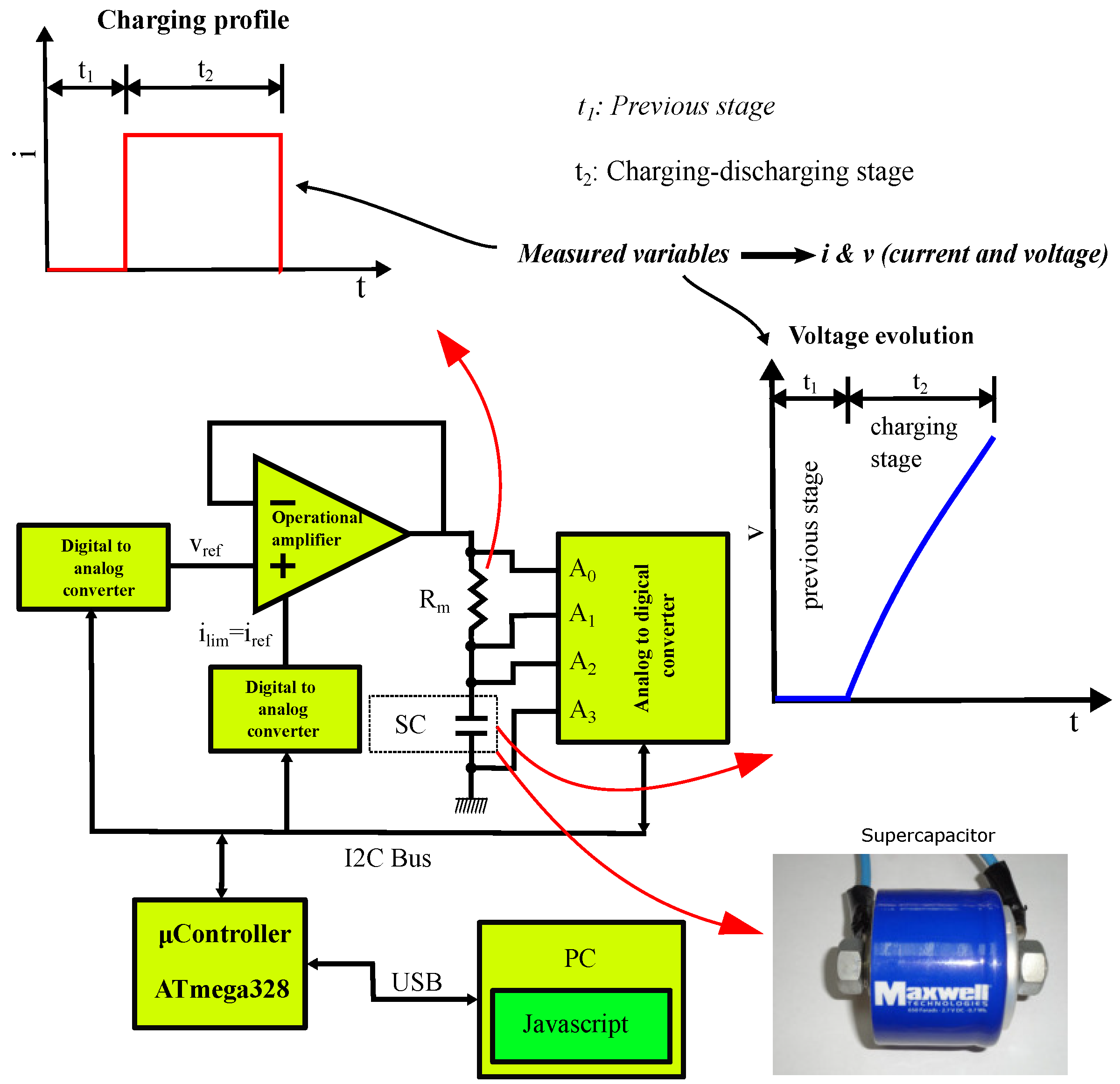
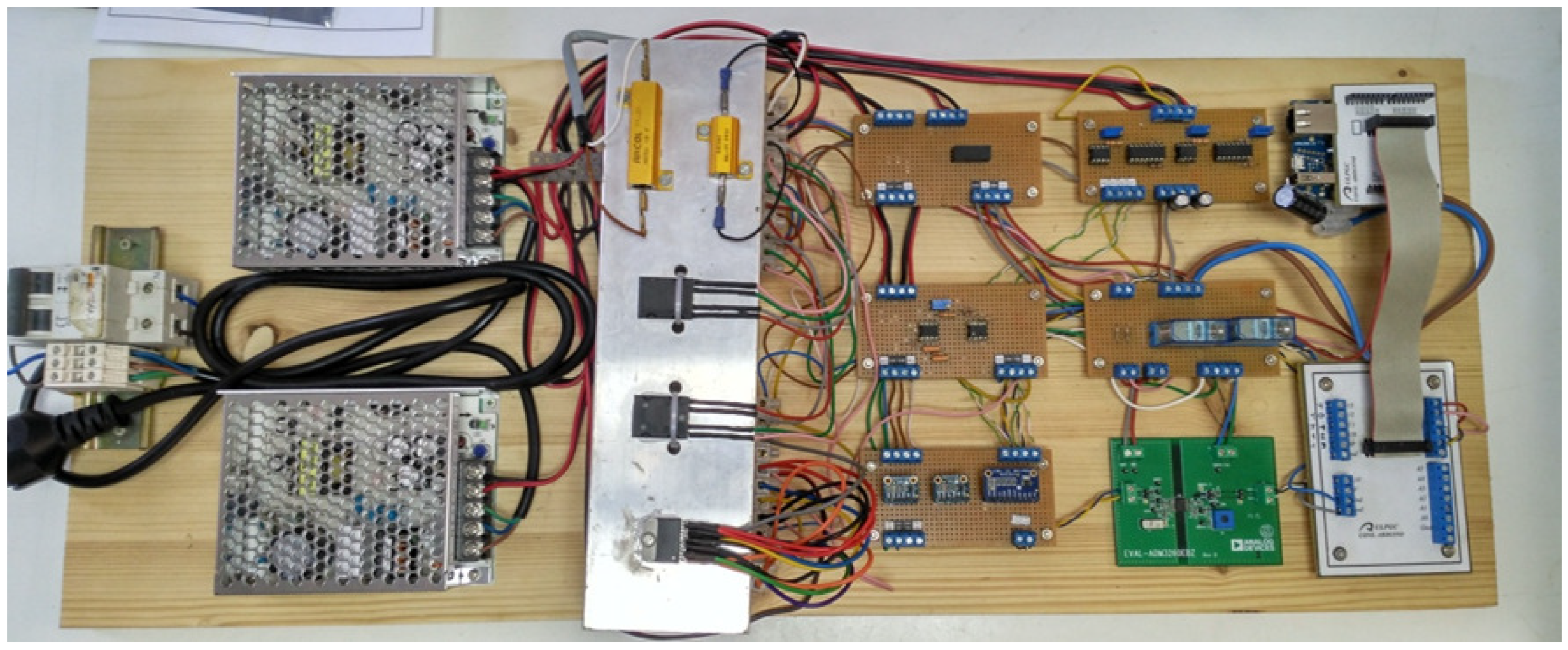
- An operational amplifier OPA549 (Texas Instruments, Dallas, TX, USA). This operational amplifier can provide a nominal current of 8 A, plus it has a special input () to limit the output current of the amplifier. This is an important feature for the implementation of galvanostatic charge and discharge processes by controlling the current.
- An analog-to-digital conversion stage (Figure 6) based on the precision converter ADS1115 (Texas Instruments), which is mounted on a board from Adafruit Industries (New York, NY, USA). This stage has two analogue channels in the differential mode, for the measurement of charge–discharge current and supercapacitor voltage. The current is measured from the voltage of a resistor in series with the supercapacitor , and the voltage is measured directly . The ADS1115 circuit has a resolution of 16 Bit, giving a resolution of 3 mV for the voltage measurement and 30 mA for the current.
- Two digital-to-analog conversion stages (Figure 7) based on a 12 Bit resolution MCP4725 (Microchip, Chandler, AZ, USA), which are mounted on a board from Adafruit Industries. These stages are used to control the charge–discharge processes of the supercapacitor, and to adjust the voltage and current references.
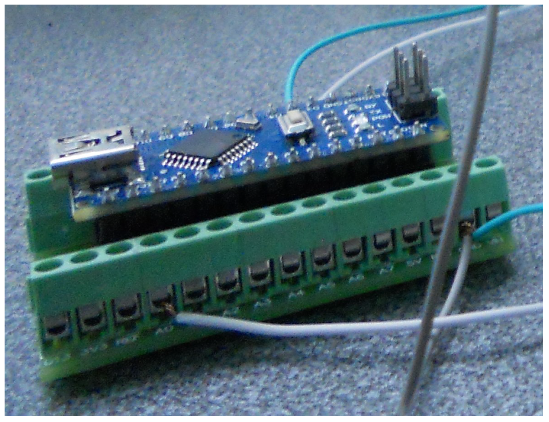
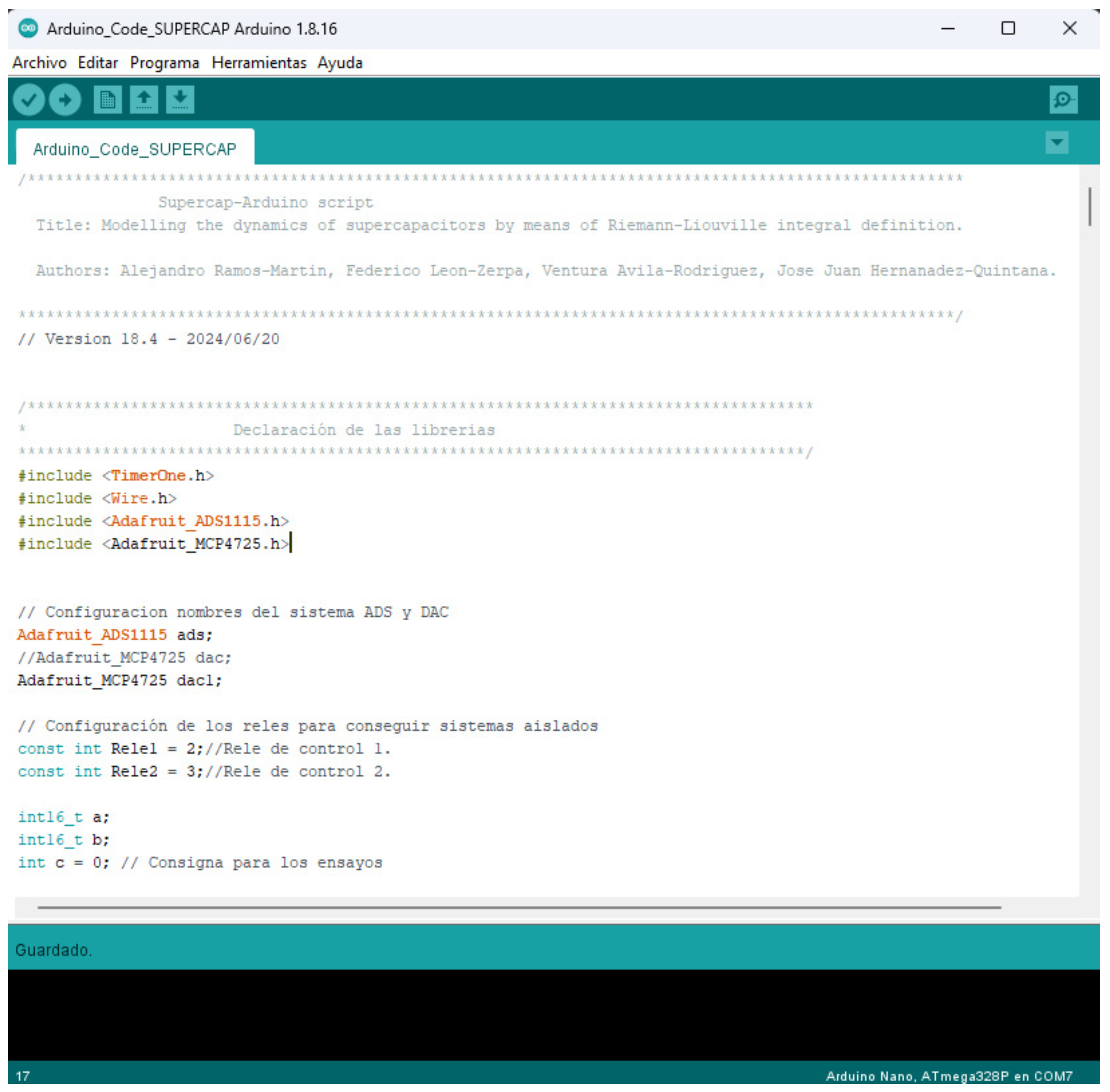
- A microcontroller model ATmega328 (Microchip) implemented on an embedded system, which is called Arduino Nano (Figure 8). This microcontroller is responsible for controlling the galvanostatic charging and discharging processes, as well as capturing data and sending it, via USB, to the PC to be saved. The microcontroller is responsible for adjusting the output voltage of the two digital-to-analogue converters: the first to set the target voltage to be applied to the output of the operational amplifier, which operates in a voltage follower configuration, and the second digital-to-analogue converter to set the charge or discharge current of the supercapacitor, thus achieving galvanostatic operation of the system. Therefore, by using the indicated devices, it is possible to implement a galvanostat that meets the requirements of the experimental design of this article, without the need for other devices.
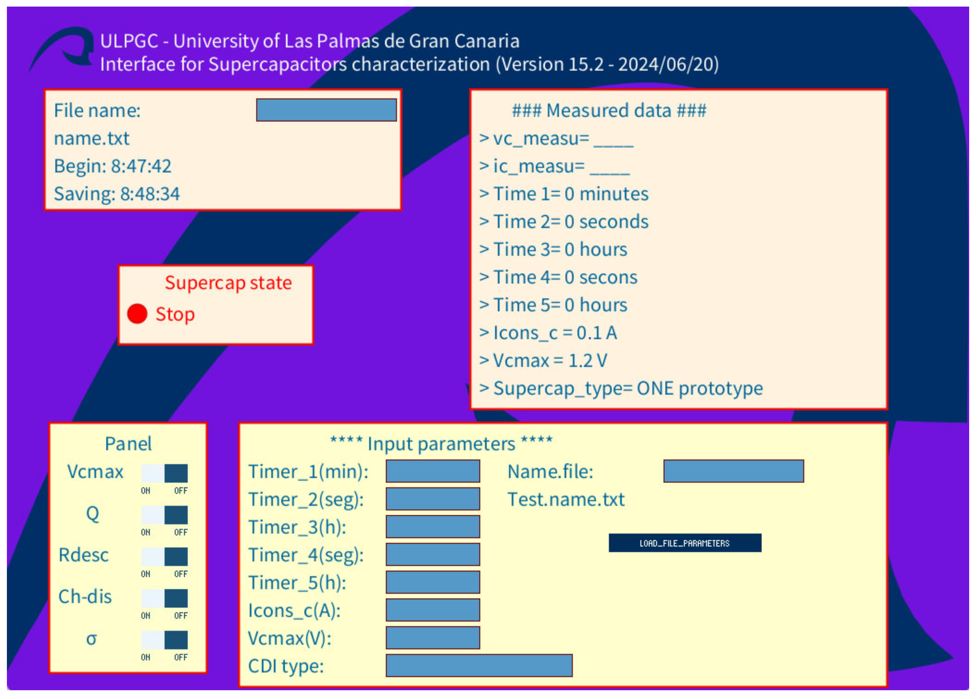
- A PC, which is responsible for controlling and configuring the microcontroller for the designed tests, as well as for storing the captured data obtained from the measurements. This is achieved by means of a program implemented in JavaScript language, under the Processing environment, Processing Foundation. This program is an interface to communicate and control the embedded system (Arduino Nano) with the PC. Processing is a flexible, open source, free, cross-platform application. There is a lot of information on the internet for programming on this platform.
5.2. Microcontroller IDE and Interface GUI
6. Results
7. Conclusions
Author Contributions
Funding
Data Availability Statement
Acknowledgments
Conflicts of Interest
Appendix A. Microcontroller Source Code
- /*************************************************************
- Supercap-Arduino script
- Title: Modelling the dynamics of supercapacitors by means of
- Riemann-Liouville integral definition.
- Authors: Alejandro Ramos-Martin, Federico Leon-Zerpa,
- Ventura Avila-Rodriguez, Jose Juan Hernanadez-Quintana.
- *************************************************************/
- // Version 18.4 - 2024/06/20
- /**********************************
- * Declaration of the libraries
- **********************************/
- #include <TimerOne.h>
- #include <Wire.h>
- #include <Adafruit_ADS1115.h>
- #include <Adafruit_MCP4725.h>
- // Configuration ADS and DAC system names
- Adafruit_ADS1115 ads;
- //Adafruit_MCP4725 dac;
- Adafruit_MCP4725 dac1;
- // Relay configuration for isolated systems
- const int Rele1 = 2;//Rele de control 1.
- const int Rele2 = 3;//Rele de control 2.
- int16_t a;
- int16_t b;
- int c = 0; // Test assignment
- unsigned long control_tiempos=0;
- uint16_t Vcuenta1=0;
- uint16_t Vcuenta2=2048;
- uint16_t Icons=2048;
- int16_t results;
- int16_t results1;
- /********************************************
- *Serial port and timer configuration
- ********************************************/
- void setup()
- {
- Serial.begin(9600);
- pinMode(Rele1, OUTPUT);
- pinMode(Rele2, OUTPUT);
- digitalWrite(Rele1, HIGH);
- digitalWrite(Rele2, HIGH);
- Timer1.initialize(100000);
- Timer1.attachInterrupt(intu);
- dac1.begin(0x62);
- //dac.begin(0x63);
- ads.begin();
- ads.setGain(GAIN_ONE);
- /******************************************
- * DAC and relays configuration
- *****************************************/
- dac1.setVoltage(2048, false);
- digitalWrite(Rele1, HIGH);//Relay NC
- digitalWrite(Rele2, HIGH);//Relay NC
- }
- void intu()
- {
- Serial.print(a);
- Serial.print(",");
- Serial.print(b);
- Serial.print(",");
- Serial.print(Icons);
- Serial.print(",");
- Serial.print(Vcmax);
- Serial.print(",");
- Serial.println(estado);
- control_tiempos=control_tiempos+1;
- }
- /**********************************************
- * Tests are carried out
- **********************************************/
- void loop(void)
- {
- Timer1.detachInterrupt();
- switch (inicio){
- //Time to 0 seconds
- case 0: //Wait or stop state.
- digitalWrite(Rele1, HIGH);//Relay NC.
- digitalWrite(Rele2, HIGH);//Relay NC.
- results1 = ads.readADC_Differential_0_1();
- results = ads.readADC_Differential_2_3();
- a = results1;
- b = results;
- control_tiempos=0;
- Timer1.attachInterrupt(intu);
- break;
- case 1: //Charging with maximum voltage setpoint.
- switch (estado){
- case 1: //Force precharge status.
- digitalWrite(Rele1, HIGH);//Open relay (NC)
- digitalWrite(Rele2, HIGH);//Open relay (NC)
- dac1.setVoltage(2048, false);
- results1 = ads.readADC_Differential_0_1();
- results = ads.readADC_Differential_2_3();
- a = results1;
- b = results;
- if(control_tiempos>=tiempo_1){
- estado=2;
- control_tiempos=0;
- }
- Timer1.attachInterrupt(intu);
- break;
- case 2: //Forced state of charge only with voltage limit.
- digitalWrite(Rele1, LOW);//Open relay (NA).
- digitalWrite(Rele2, LOW);//Open relay (NA).
- dac1.setVoltage(Icons, false);
- results1 = ads.readADC_Differential_0_1();
- results = ads.readADC_Differential_2_3();
- a = results1;
- b = results;
- if (a > Vcmax) {
- estado=3;//Self-discharge status
- control_tiempos=0;
- digitalWrite(Rele1, HIGH);//Relay NC.
- digitalWrite(Rele2, HIGH);//Relay NC.
- // Corriente
- dac1.setVoltage(2048, false);
- }
- Timer1.attachInterrupt(intu);
- break;
- case 3://Force self-discharge status.
- results1 = ads.readADC_Differential_0_1();
- results = ads.readADC_Differential_2_3();
- a = results1;
- b = results;
- if(control_tiempos>=tiempo_3){
- estado=4;
- inicio=0;
- control_tiempos=0;
- }
- Timer1.attachInterrupt(intu);
- break;
- }
- //End switch (estado)
- break;
- case 2://Charging with electrical charge setpoint.
- switch (estado){
- case 1: //Force precharge status.
- digitalWrite(Rele1, HIGH);//Relay NC.
- digitalWrite(Rele2, HIGH);//Relay NC.
- dac1.setVoltage(2048, false);
- results1 = ads.readADC_Differential_0_1();
- results = ads.readADC_Differential_2_3();
- a = results1;
- b = results;
- if(control_tiempos>=tiempo_1){
- estado=2;
- control_tiempos=0;
- }
- Timer1.attachInterrupt(intu);
- break;
- case 2://Force state of charge with time limit 2.
- digitalWrite(Rele1, HIGH);//Relay NC.
- digitalWrite(Rele2, HIGH);//Relay NC.
- dac1.setVoltage(Icons, false);
- results1 = ads.readADC_Differential_0_1();
- results = ads.readADC_Differential_2_3();
- a = results1;
- b = results;
- if (a > Vcmax) {
- estado=3;// Self-discharge status
- control_tiempos=0;
- digitalWrite(Rele1, LOW);//Relay NA.
- digitalWrite(Rele2, LOW);//Relay NA.
- dac1.setVoltage(2048, false);
- }
- if(control_tiempos>=tiempo_2){
- estado=3;// Self-discharge status
- control_tiempos=0;
- digitalWrite(Rele1, HIGH);//Relay NC.
- digitalWrite(Rele2, HIGH);//Relay NC.
- dac1.setVoltage(2048, false);
- }
- Timer1.attachInterrupt(intu);
- break;
- case 3:// Force self-discharge status.
- results1 = ads.readADC_Differential_0_1();
- results = ads.readADC_Differential_2_3();
- a = results1;
- b = results;
- if(control_tiempos>=tiempo_3){
- estado=4;// Test completed
- inicio=0;
- control_tiempos=0;
- }
- Timer1.attachInterrupt(intu);
- break;
- }//Fin switch (estado)
- break;
- case 3:// Indefinite discharge is forced with discharge resistance.
- digitalWrite(Rele1, HIGH);//Relay NC.
- digitalWrite(Rele2, HIGH);//Relay NC.
- dac1.setVoltage(2048, false);
- results1 = ads.readADC_Differential_0_1();
- results = ads.readADC_Differential_2_3();
- a = results1;
- b = results;
- control_tiempos=0;
- Timer1.attachInterrupt(intu);
- break;
- case 4:// CDI charging and discharging
- switch (estado){
- case 1: //Force precharge status.
- digitalWrite(Rele1, HIGH);//Open relay (NC)
- digitalWrite(Rele2, HIGH);//open relay (NC)
- dac1.setVoltage(2048, false);
- results1 = ads.readADC_Differential_0_1();
- results = ads.readADC_Differential_2_3();
- a = results1;
- b = results;
- if(control_tiempos>=tiempo_1){
- estado=2;
- control_tiempos=0;
- }
- Timer1.attachInterrupt(intu);
- break;
- case 2:
- digitalWrite(Rele1, LOW);//Open relay (NA).
- digitalWrite(Rele2, LOW);//Open relay (NA).
- dac1.setVoltage(Icons, false);
- results1 = ads.readADC_Differential_0_1();
- results = ads.readADC_Differential_2_3();
- a = results1;
- b = results;
- if (a > Vcmax) {
- estado=3;//Self-discharge status
- control_tiempos=0;
- digitalWrite(Rele1, HIGH);//Relay NC.
- digitalWrite(Rele2, HIGH);//Relay NC.
- dac1.setVoltage(2048, false);
- }
- Timer1.attachInterrupt(intu); //The interruption of data sending is enabled.
- break;
- case 3:
- dac1.setVoltage(Icons, false);
- results1 = ads.readADC_Differential_0_1();
- results = ads.readADC_Differential_2_3();
- a = results1;
- b = results;
- break
- case 4:
- dac1.setVoltage(Icons, false);
- results1 = ads.readADC_Differential_0_1();
- results = ads.readADC_Differential_2_3();
- a = results1;
- b = results;
- if (a > Vcmax) {
- estado=3;
- control_tiempos=0;
- digitalWrite(Rele1, HIGH);
- digitalWrite(Rele2, HIGH);
- // Corriente
- dac1.setVoltage(2048, false);
- }
- Timer1.attachInterrupt(intu);
- break;
- case 5://Force self-discharge status.
- results1 = ads.readADC_Differential_0_1();
- results = ads.readADC_Differential_2_3();
- a = results1;
- b = results;
- if(control_tiempos>=tiempo_3){
- estado=4;//Test completed
- inicio=0;
- control_tiempos=0;
- }
- Timer1.attachInterrupt(intu);
- break;
- }
- }//End switch(inicio)
- }//End void loop()
- /****************************************************
- * Serial Event Stage
- *****************************************************/
- /*
- * C ---> The order of the test
- * Por ejemplo:
- * Inicio --> 2
- * Tiempo_1-> 50
- * Tiempo_2-> 200
- * Tiempo_3-> 50
- ** Tiempo_4-> 100
- ** Tiempo_5-> 100
- * Icons --> 1500
- * Vcmax --> 1000
- */
- void serialEvent(){
- if (Serial.peek() == ’c’) {
- Timer1.detachInterrupt();
- Serial.read();
- inicio = Serial.parseInt();
- tiempo_1 = Serial.parseInt();
- tiempo_2 = Serial.parseInt();
- tiempo_3 = Serial.parseInt();
- tiempo_4 = Serial.parseInt();
- tiempo_5 = Serial.parseInt();
- Icons = Serial.parseInt();
- Vcmax = Serial.parseInt();
- estado=1;
- control_tiempos=0;
- Timer1.attachInterrupt(intu);
- }
- while (Serial.available() > 0){
- Serial.read();
- }
- }
Appendix B. Processing Source Code
- /****************************************************************************************************
- Supercap-Processing script GUI
- Title: Modelling the dynamics of supercapacitors by means of
- Riemann-Liouville integral definition.
- Authors: Alejandro Ramos-Martin, Federico Leon-Zerpa,
- Ventura Avila-Rodriguez, Jose Juan Hernanadez-Quintana.
- ****************************************************************************************************/
- // Version 15.2 - 2024/06/20
- import processing.serial.*;
- import controlP5.*;
- String nom_archivo="name.txt",para_nom_archivo="name.txt",estado_CDI="Stop";
- String hora_inicio="Begin: "+hour()+":"+minute()+":"+second();
- String tiempo_1="0",tiempo_2="0",tiempo_3="0", tiempo_4="0", tiempo_5="0", tipo_CDI="ONE";
- String I_c="0,1",V_c="1,2";
- String tipo_ensayo="0";
- PrintWriter archivo;//Data file test pointer.
- PrintWriter fichero;//Parameters file pointer.
- ControlP5 cp5;
- Serial myPort;
- boolean serialInited;
- int muestras_segundo=10;
- int finalizado=0;
- int xPos = 1;
- int esquina_x=600;
- int esquina_y=100;
- int ancho=1200;
- int alto=600;
- int pocision_alto=0;
- int guardar_datos=-1,inicio=0;
- String dato_1="____",dato_2="____",dato_3="____",dato_4="____";
- String dato_5="____",dato_6="____";
- PShape bot;
- // Button configuration
- int ancho_ventana=3020,alto_ventana=1500;
- int x_r1=500,y_r1=90,dx_r1=450,dy_r1=345;
- int mx_r1=10,my_r1=30,dy_t=30;
- int x_r2=40,y_r2=90,dx_r2=385,dy_r2=130;
- int mx_r2=10,my_r2=30;
- int ancho_campo_texto=210;
- int x_resto=40,y_resto=250,dy_resto=25;
- int x_r3=40,y_r3=300,dx_r3=210,dy_r3=35;
- int mx_r3=10,my_r3=30;
- int ancho_boton=110,alto_boton=20,ancho_mitad_boton=55;
- int x_r4=250,y_r4=450,dx_r4=700,dy_r4=285;
- int mx_r4=10,my_r4=30;
- int ancho_campo_texto_4=150;
- int x_r5=45,y_r5=450,dx_r5=170,dy_r5=270;
- int mx_r5=10,my_r5=30;
- int x_r6=120,y_r6=280,dx_r6=210,dy_r6=85;
- int mx_r6=10,my_r6=30;
- int lf = 10;
- int BAUD_RATE=9600;
- String inString=null;
- void setup () {
- cp5 = new ControlP5(this);
- cp5.addButton("load_file_parameters")
- .setValue(0)
- .setPosition(x_r4+40*mx_r4,y_r4+4*my_r4)
- .setSize(ancho_boton+ancho_mitad_boton,alto_boton)
- ;
- cp5.addTextfield("nom_archivo")
- .setPosition(x_r2+2*mx_r2+ancho_campo_texto, y_r2+my_r2/3)
- .setSize(150,25)
- .setCaptionLabel("")
- .setColorBackground(color(84,153,199))
- .setColorActive(color(100,0,0))
- .setColorForeground(color(100,0,0))
- .setFont(createFont("times new roman",20))
- ;
- cp5.addTextfield("para_nom_archivo")
- .setPosition(x_r4+25*mx_r4+ancho_campo_texto, y_r4+4*my_r4/3)
- .setSize(150,25)
- .setCaptionLabel("")
- .setColorBackground(color(84,153,199))
- .setColorActive(color(100,0,0))
- .setColorForeground(color(100,0,0))
- .setFont(createFont("times new roman",20))
- ;
- cp5.addTextfield("tiempo_1")
- .setPosition(x_r4+mx_r4+ancho_campo_texto_4, y_r4+my_r4+dy_t/3)
- .setSize(100,25)
- .setCaptionLabel("")
- .setColorBackground(color(84,153,199))
- .setColorActive(color(100,0,0))
- .setColorForeground(color(100,0,0))
- .setFont(createFont("times new roman",20))
- ;
- cp5.addTextfield("tiempo_2")
- .setPosition(x_r4+mx_r4+ancho_campo_texto_4, y_r4+my_r4+4*dy_t/3)
- .setSize(100,25)
- .setCaptionLabel("")
- .setColorBackground(color(84,153,199))
- .setColorActive(color(100,0,0))
- .setColorForeground(color(100,0,0))
- .setFont(createFont("times new roman",20))
- ;
- cp5.addTextfield("tiempo_3")
- .setPosition(x_r4+mx_r4+ancho_campo_texto_4, y_r4+my_r4+7*dy_t/3)
- .setSize(100,25)
- .setCaptionLabel("")
- .setColorBackground(color(84,153,199))
- .setColorActive(color(100,0,0))
- .setColorForeground(color(100,0,0))
- .setFont(createFont("times new roman",20))
- ;
- cp5.addTextfield("tiempo_4")
- .setPosition(x_r4+mx_r4+ancho_campo_texto_4, y_r4+my_r4+10*dy_t/3)
- .setSize(100,25)
- .setCaptionLabel("")
- .setColorBackground(color(84,153,199))
- .setColorActive(color(100,0,0))
- .setColorForeground(color(100,0,0))
- .setFont(createFont("times new roman",20))
- ;
- cp5.addTextfield("tiempo_5")
- .setPosition(x_r4+mx_r4+ancho_campo_texto_4, y_r4+my_r4+13*dy_t/3)
- .setSize(100,25)
- .setCaptionLabel("")
- .setColorBackground(color(84,153,199))
- .setColorActive(color(100,0,0))
- .setColorForeground(color(100,0,0))
- .setFont(createFont("times new roman",20))
- ;
- cp5.addTextfield("I_c")
- .setPosition(x_r4+mx_r4+ancho_campo_texto_4, y_r4+my_r4+16*dy_t/3)
- .setSize(100,25)
- .setCaptionLabel("")
- .setColorBackground(color(84,153,199))
- .setColorActive(color(100,0,0))
- .setColorForeground(color(100,0,0))
- .setFont(createFont("times new roman",20))
- ;
- cp5.addTextfield("V_c")
- .setPosition(x_r4+mx_r4+ancho_campo_texto_4, y_r4+my_r4+19*dy_t/3)
- .setSize(100,25)
- .setCaptionLabel("")
- .setColorBackground(color(84,153,199))
- .setColorActive(color(100,0,0))
- .setColorForeground(color(100,0,0))
- .setFont(createFont("times new roman",20))
- ;
- cp5.addTextfield("tipo_CDI")
- .setPosition(x_r4+mx_r4+ancho_campo_texto_4, y_r4+my_r4+22*dy_t/3)
- .setSize(200,25)
- .setCaptionLabel("")
- .setColorBackground(color(84,153,199))
- .setColorActive(color(100,0,0))
- .setColorForeground(color(100,0,0))
- .setFont(createFont("times new roman",20))
- ;
- cp5.addToggle("tension_max")
- .setPosition(x_r5+10*mx_r5,y_r5+3*my_r5/2)
- .setSize(50,20)
- .setCaptionLabel("on off")
- .setColorLabel(color(21,67,96))
- .setColorBackground(color(235,245,251))
- .setColorActive(color(26,82,118))
- .setValue(false)
- .setMode(ControlP5.SWITCH)
- ;
- cp5.addToggle("carga_culombios")
- .setPosition(x_r5+10*mx_r5,y_r5+6*my_r5/2)
- .setSize(50,20)
- .setCaptionLabel("on off")
- .setColorLabel(color(21,67,96))
- .setColorBackground(color(235,245,251))
- .setColorActive(color(26,82,118))
- .setValue(false)
- .setMode(ControlP5.SWITCH)
- ;
- cp5.addToggle("descarga_resistencia")
- .setPosition(x_r5+10*mx_r5,y_r5+9*my_r5/2)
- .setSize(50,20)
- .setCaptionLabel("on off")
- .setColorLabel(color(21,67,96))
- .setColorBackground(color(235,245,251))
- .setColorActive(color(26,82,118))
- .setValue(false)
- .setMode(ControlP5.SWITCH)
- ;
- cp5.addToggle("carga_descarga")
- .setPosition(x_r5+10*mx_r5,y_r5+12*my_r5/2)
- .setSize(50,20)
- .setCaptionLabel("on off")
- .setColorLabel(color(21,67,96))
- .setColorBackground(color(235,245,251))
- .setColorActive(color(26,82,118))
- .setValue(false)
- .setMode(ControlP5.SWITCH)
- ;
- cp5.addToggle("conductimetro")
- .setPosition(x_r5+10*mx_r5,y_r5+15*my_r5/2)
- .setSize(50,20)
- .setCaptionLabel("on off")
- .setColorLabel(color(21,67,96))
- .setColorBackground(color(235,245,251))
- .setColorActive(color(26,82,118))
- .setValue(false)
- .setMode(ControlP5.SWITCH)
- ;
- /***************************************************************************
- Configuration window GUI
- ***************************************************************************/
- size(1040,740);
- stroke(227,10,10);
- println(Serial.list());
- myPort = new Serial(this, Serial.list()[0], 9600);
- myPort.clear();
- myPort.buffer(80);
- inString = myPort.readStringUntil(lf);
- inString = null;
- background(113,023,220);
- bot = loadShape("ULPGC.svg");
- shape(bot, 22, 22, 72, 52);
- shape(bot, -100,-100);
- color(26,82,118);
- String s_1="ULPGC - University of Las Palmas de Gran Canaria";
- String s_2="Interface for Supercapacitors characterization (Version 15.2 - 2024/06/20)";
- textSize(22);
- fill(248, 249, 249);
- text(s_1, 100, 45);
- text(s_2, 100, 70);
- }
- /*********************************************************************************
- Test configuration
- **********************************************************************************/
- void tension_max(boolean theFlag) {
- if(theFlag==true) {
- fichero = createWriter("Ensayo."+nom_archivo);
- fichero.print("Test 1: ");
- fichero.println("Charge Vcmax y self-discharge");
- fichero.print("CDI type: ");
- fichero.println(tipo_CDI);
- fichero.print("Time 1: ");
- fichero.println(tiempo_1);
- fichero.print("Time 2: ");
- fichero.println(tiempo_2);
- fichero.print("Time 3: ");
- fichero.println(tiempo_3);
- fichero.print("Ic: ");
- fichero.println(I_c);
- fichero.print("Vcmax: ");
- fichero.println(V_c);
- fichero.flush();
- fichero.close();
- // Test 1: with reference Vcmax and selfdischarge
- inicio = 1;
- String Vc_arduino=str(convierte_Vcmax_cuentas(V_c));
- String Ic_arduino=str(convierte_Icons_cuentas(I_c));
- String tiempo_3_arduino=str(convierte_tiempo_horas(tiempo_3));
- String tiempo_1_arduino=str(convierte_tiempo_minutos(tiempo_1));
- String tiempo_2_arduino=str(convierte_tiempo_segundos(tiempo_2));
- String i="";
- String t1="";
- String t2="";
- String t3="";
- String ic="";
- String vcmax="";
- i=str(inicio);
- t1=tiempo_1_arduino;
- t2=tiempo_2_arduino;
- t3=tiempo_3_arduino;
- ic=Ic_arduino;
- vcmax=Vc_arduino;
- tipo_ensayo="1"; // Maximum voltage test Vcmax
- myPort.write("c");
- myPort.write(i);
- myPort.write(",");
- myPort.write(t1);
- myPort.write(",");
- myPort.write(t2);
- myPort.write(",");
- myPort.write(t3);
- myPort.write(",");
- myPort.write(ic);
- myPort.write(",");
- myPort.write(vcmax);
- hora_inicio="Comienzo: "+hour()+":"+minute()+":"+second();
- if(archivo==null){
- }else{
- archivo.flush();
- archivo.close();
- }
- archivo = createWriter(nom_archivo);// a text file is created
- nom_archivo="I-"+nom_archivo;
- }else{
- //STOP de CDI
- String i=""+0;
- String t1=""+0;
- String t2=""+0;
- String t3=""+0;
- String ic=""+4095;
- String vcmax=""+1000;
- tipo_ensayo="0";
- myPort.write("c");
- myPort.write(i);
- myPort.write(",");
- myPort.write(t1);
- myPort.write(",");
- myPort.write(t2);
- myPort.write(",");
- myPort.write(t3);
- myPort.write(",");
- myPort.write(ic);
- myPort.write(",");
- myPort.write(vcmax);
- if(archivo==null){
- } else {
- archivo.flush();
- archivo.close();
- }
- }
- }
- void carga_culombios(boolean theFlag) {
- if(theFlag==true) {
- fichero = createWriter("parameters."+nom_archivo);
- fichero.print("Test 2: ");
- fichero.println("Current density");
- fichero.print("CDI type");
- fichero.println(tipo_CDI);
- fichero.print("Time 1: ");
- fichero.println(tiempo_1);
- fichero.print("Time 2: ");
- fichero.println(tiempo_2);
- fichero.print("Time 3: ");
- fichero.println(tiempo_3);
- fichero.print("Ic: ");
- fichero.println(I_c);
- fichero.print("Vcmax: ");
- fichero.println(V_c);
- fichero.flush();
- fichero.close();
- //Ensayo 2: Electric charge Q
- /*
- I=Coulombs/time ---> With t2 is another test for charge-discharge
- */
- inicio = 2;
- String Vc_arduino=str(convierte_Vcmax_cuentas(V_c));
- String Ic_arduino=str(convierte_Icons_cuentas(I_c));
- String tiempo_3_arduino=str(convierte_tiempo_horas(tiempo_3));
- String tiempo_1_arduino=str(convierte_tiempo_minutos(tiempo_1));
- String tiempo_2_arduino=str(convierte_tiempo_segundos(tiempo_2));
- String i=""+inicio;
- String t1=""+tiempo_1_arduino;
- String t2=""+tiempo_2_arduino;
- String t3=""+tiempo_3_arduino;
- String ic=""+Ic_arduino;
- String vcmax=""+Vc_arduino;
- tipo_ensayo="2";
- myPort.write("c");
- myPort.write(i);
- myPort.write(",");
- myPort.write(t1);
- myPort.write(",");
- myPort.write(t2);
- myPort.write(",");
- myPort.write(t3);
- myPort.write(",");
- myPort.write(ic);
- myPort.write(",");
- myPort.write(vcmax);
- hora_inicio="Begin: "+hour()+":"+minute()+":"+second();
- if(archivo==null){
- } else {
- archivo.flush();
- archivo.close();
- }
- archivo = createWriter(nom_archivo);
- nom_archivo="I-"+nom_archivo;
- } else {
- String i=""+0;
- String t1=""+0;
- String t2=""+0;
- String t3=""+0;
- String ic=""+4095;
- String vcmax=""+1000;
- tipo_ensayo="0";
- myPort.write("c");
- myPort.write(i);
- myPort.write(",");
- myPort.write(t1);
- myPort.write(",");
- myPort.write(t2);
- myPort.write(",");
- myPort.write(t3);
- myPort.write(",");
- myPort.write(ic);
- myPort.write(",");
- myPort.write(vcmax);
- if(archivo==null){
- } else {
- archivo.flush();
- archivo.close();
- }
- }
- }
- void descarga_resistencia(boolean theFlag) {
- if(theFlag==true) {
- inicio = 3;
- String i=""+inicio;
- String t1=""+tiempo_1;
- String t2=""+tiempo_2;
- String t3=""+tiempo_3;
- String ic=""+I_c;
- String vcmax=""+V_c;
- tipo_ensayo="3";
- myPort.write("c");
- myPort.write(i);
- myPort.write(",");
- myPort.write(t1);
- myPort.write(",");
- myPort.write(t2);
- myPort.write(",");
- myPort.write(t3);
- myPort.write(",");
- myPort.write(ic);
- myPort.write(",");
- myPort.write(vcmax);
- if(archivo==null){
- } else {
- archivo.flush();
- archivo.close();
- }
- } else {
- String i=""+0;
- String t1=""+0;
- String t2=""+0;
- String t3=""+0;
- String ic=""+4095;
- String vcmax=""+1000;
- tipo_ensayo="0";//CDI Stop
- myPort.write("c");
- myPort.write(i);
- myPort.write(",");
- myPort.write(t1);
- myPort.write(",");
- myPort.write(t2);
- myPort.write(",");
- myPort.write(t3);
- myPort.write(",");
- myPort.write(ic);
- myPort.write(",");
- myPort.write(vcmax);
- if(archivo==null){}
- else{
- archivo.flush();
- archivo.close();
- }
- }
- }
- void carga_descarga (boolean theFlag) {
- if(theFlag==true) {
- fichero = createWriter("test_4."+nom_archivo);
- fichero.print("Test 4: ");
- fichero.println("Charge and discharge of the CDI");
- fichero.print("CDI type: ");
- fichero.println(tipo_CDI);
- fichero.print("Time 1: ");
- fichero.println(tiempo_1);
- fichero.print("Time 2: ");
- fichero.println(tiempo_2);
- fichero.print("Time 3: ");
- fichero.println(tiempo_3);
- fichero.print("Time 4: ");
- fichero.println(tiempo_4);
- fichero.print("Time 5: ");
- fichero.println(tiempo_5);
- fichero.print("Ic: ");
- fichero.println(I_c);
- fichero.print("Vcmax: ");
- fichero.println(V_c);
- fichero.flush();
- fichero.close();
- inicio = 4;
- String Vc_arduino=str(convierte_Vcmax_cuentas(V_c));
- String Ic_arduino=str(convierte_Icons_cuentas(I_c));
- String tiempo_3_arduino=str(convierte_tiempo_horas(tiempo_3));
- String tiempo_1_arduino=str(convierte_tiempo_minutos(tiempo_1));
- String tiempo_2_arduino=str(convierte_tiempo_segundos(tiempo_2));
- String tiempo_4_arduino=str(convierte_tiempo_segundos(tiempo_4));
- String tiempo_5_arduino=str(convierte_tiempo_horas(tiempo_5));
- String i="";
- String t1="";
- String t2="";
- String t3="";
- String t4="";
- String t5="";
- String ic="";
- String vcmax="";
- i=str(inicio);
- t1=tiempo_1_arduino;
- t2=tiempo_2_arduino;
- t3=tiempo_3_arduino;
- t4=tiempo_4_arduino;
- t5=tiempo_5_arduino;
- ic=Ic_arduino;
- vcmax=Vc_arduino;
- tipo_ensayo="4";
- myPort.write("c");
- myPort.write(i);
- myPort.write(",");
- myPort.write(t1);
- myPort.write(",");
- myPort.write(t2);
- myPort.write(",");
- myPort.write(t3);
- myPort.write(",");
- myPort.write(t4);
- myPort.write(",");
- myPort.write(t5);
- myPort.write(",");
- myPort.write(ic);
- myPort.write(",");
- myPort.write(vcmax);
- hora_inicio="Comienzo: "+hour()+":"+minute()+":"+second();
- if(archivo==null){
- }else{
- archivo.flush();
- archivo.close();
- }
- archivo = createWriter(nom_archivo);
- nom_archivo="I-"+nom_archivo;
- }else{
- //STOP CDI
- String i=""+0;
- String t1=""+0;
- String t2=""+0;
- String t3=""+0;
- String t4=""+0;
- String t5=""+0;
- String ic=""+4095;
- String vcmax=""+1000;
- tipo_ensayo="0";
- myPort.write("c");
- myPort.write(i);
- myPort.write(",");
- myPort.write(t1);
- myPort.write(",");
- myPort.write(t2);
- myPort.write(",");
- myPort.write(t3);
- myPort.write(",");
- myPort.write(t4);
- myPort.write(",");
- myPort.write(t5);
- myPort.write(",");
- myPort.write(ic);
- myPort.write(",");
- myPort.write(vcmax);
- if(archivo==null){
- } else {
- archivo.flush();
- archivo.close();
- }
- }
- }
- void conductimetro(boolean theFlag) {
- if(theFlag==true) {
- fichero = createWriter("Test."+nom_archivo);
- fichero.print("Test 5: ");
- fichero.println("conductimeter CDI");
- fichero.print("CDI type: ");
- fichero.println(tipo_CDI);
- fichero.print("Time 1: ");
- fichero.println(tiempo_1);
- fichero.print("Time 2: ");
- fichero.println(tiempo_2);
- fichero.print("Time 3: ");
- fichero.println(tiempo_3);
- fichero.print("Ic: ");
- fichero.println(I_c);
- fichero.print("Vcmax: ");
- fichero.println(V_c);
- fichero.flush();
- fichero.close();
- inicio = 5;
- String Vc_arduino=str(convierte_Vcmax_cuentas(V_c));
- String Ic_arduino=str(convierte_Icons_cuentas(I_c));
- String tiempo_3_arduino=str(convierte_tiempo_horas(tiempo_3));
- String tiempo_1_arduino=str(convierte_tiempo_minutos(tiempo_1));
- String tiempo_2_arduino=str(convierte_tiempo_segundos(tiempo_2));
- String i="";
- String t1="";
- String t2="";
- String t3="";
- String ic="";
- String vcmax="";
- i=str(inicio);
- t1=tiempo_1_arduino;
- t2=tiempo_2_arduino;
- t3=tiempo_3_arduino;
- ic=Ic_arduino;
- vcmax=Vc_arduino;
- tipo_ensayo="5";
- myPort.write("c");
- myPort.write(i);
- myPort.write(",");
- myPort.write(t1);
- myPort.write(",");
- myPort.write(t2);
- myPort.write(",");
- myPort.write(t3);
- myPort.write(",");
- myPort.write(ic);
- myPort.write(",");
- myPort.write(vcmax);
- hora_inicio="Begin: "+hour()+":"+minute()+":"+second();
- if(archivo==null){
- }else{
- archivo.flush();
- archivo.close();
- }
- archivo = createWriter(nom_archivo);// Se crea un TXT
- nom_archivo="I-"+nom_archivo;
- }else{
- //STOP de CDI
- String i=""+0;
- String t1=""+0;
- String t2=""+0;
- String t3=""+0;
- String ic=""+4095;
- String vcmax=""+1000;
- tipo_ensayo="0";
- myPort.write("c");
- myPort.write(i);
- myPort.write(",");
- myPort.write(t1);
- myPort.write(",");
- myPort.write(t2);
- myPort.write(",");
- myPort.write(t3);
- myPort.write(",");
- myPort.write(ic);
- myPort.write(",");
- myPort.write(vcmax);
- if(archivo==null){
- } else {
- archivo.flush();
- archivo.close();
- }
- }
- }
- /*********************************************************************************
- Interface configuration
- **********************************************************************************/
- void draw () {
- // Comand DRAW
- fill(255, 243, 224);
- rect(x_r1,y_r1,dx_r1,dy_r1);
- color(250,0,0,205);
- fill(0, 102, 153);
- text(" ### Measured data ###", x_r1+mx_r1, y_r1+my_r1);
- text("> vc_measu= "+dato_1, x_r1+mx_r1, y_r1+my_r1+dy_t);
- text("> ic_measu= "+dato_2, x_r1+mx_r1, y_r1+my_r1+2*dy_t);
- text("> Time 1= "+tiempo_1+" minutes", x_r1+mx_r1, y_r1+my_r1+3*dy_t);
- text("> Time 2= "+tiempo_2+" seconds", x_r1+mx_r1, y_r1+my_r1+4*dy_t);
- text("> Time 3= "+tiempo_3+" hours", x_r1+mx_r1, y_r1+my_r1+5*dy_t);
- text("> Time 4= "+tiempo_4+" secons", x_r1+mx_r1, y_r1+my_r1+6*dy_t);
- text("> Time 5= "+tiempo_5+" hours", x_r1+mx_r1, y_r1+my_r1+7*dy_t);
- text("> Icons_c = "+I_c+" A", x_r1+mx_r1, y_r1+my_r1+8*dy_t);
- text("> Vcmax = "+V_c+" V", x_r1+mx_r1, y_r1+my_r1+9*dy_t);
- text("> Supercap_type= "+tipo_CDI+" prototype", x_r1+mx_r1, y_r1+my_r1+10*dy_t);
- fill(255, 243, 224);
- rect(x_r2,y_r2,dx_r2,dy_r2);
- color(250,0,0,205);
- fill(0, 102, 153);
- text("File name:",x_r2+mx_r2, y_r2+my_r2);
- text(nom_archivo,x_r2+mx_r2, y_r2+my_r2+dy_t);
- text(hora_inicio,x_r2+mx_r2, y_r2+my_r2+2*dy_t);
- text("Saving: "+hour()+":"+minute()+":"+second(),x_r2+mx_r2, y_r2+my_r2+3*dy_t);
- fill(255, 255, 255);
- strokeWeight(1);
- color(250,0,0,255);
- strokeWeight(2);
- // Input parameter panel interface configuration
- fill(255, 355, 205);
- rect(x_r4,y_r4,dx_r4,dy_r4);
- color(250,0,0,205);
- fill(0, 102, 153);
- text(" **** Input parameters **** ", x_r4+mx_r4, y_r4+my_r4);
- text("Timer_1(min): ", x_r4+mx_r4, y_r4+my_r4+dy_t);
- text("Timer_2(seg): ", x_r4+mx_r4, y_r4+my_r4+2*dy_t);
- text("Timer_3(h): ", x_r4+mx_r4, y_r4+my_r4+3*dy_t);
- text("Timer_4(seg): ", x_r4+mx_r4, y_r4+my_r4+4*dy_t);
- text("Timer_5(h): ", x_r4+mx_r4, y_r4+my_r4+5*dy_t);
- text("Icons_c(A): ", x_r4+mx_r4, y_r4+my_r4+6*dy_t);
- text("Vcmax(V): ", x_r4+mx_r4, y_r4+my_r4+7*dy_t);
- text("CDI type: ", x_r4+mx_r4, y_r4+my_r4+8*dy_t);
- text("Name.file:",x_r4+29*mx_r4, y_r4+2*my_r4);
- text("Test."+para_nom_archivo,x_r4+29*mx_r4, y_r4+2*my_r4+dy_t);
- fill(255, 355, 205);
- rect(x_r5,y_r5,dx_r5,dy_r5);
- color(250,0,0,205);
- fill(0, 102, 153);
- text("Panel", x_r5+6*mx_r5, y_r5+my_r5);
- text("Vcmax ", x_r5+2*mx_r5, y_r5+my_r5+1*dy_t);
- text("Q", x_r5+4*mx_r5, y_r5+my_r5+5*dy_t/2);
- text("Rdesc", x_r5+mx_r5, y_r5+my_r5+8*dy_t/2);
- text("Ch-dis", x_r5+mx_r5, y_r5+my_r5+11*dy_t/2);
- text("chi", x_r5+4*mx_r5, y_r5+my_r5+14*dy_t/2);
- fill(255, 243, 224);
- rect(x_r6,y_r6,dx_r6,dy_r6);
- color(255,255,0,0);
- fill(255, 0, 0);
- ellipse(x_r6+2*mx_r4, y_r6+3.5*my_r6/2, 20, 20);
- text(estado_CDI,x_r6+4*mx_r6,y_r6+2.5*my_r6/1.25);
- text("Supercap state", x_r6+5*mx_r6, y_r6+0.85*my_r6);
- }
- void serialEvent (Serial myPort) {
- try{
- inString = myPort.readStringUntil(’\n’);
- inString = trim(inString);
- if (inString != null) {
- String[] lista = split(inString,",");
- dato_1=lista[0];
- dato_2=lista[1];
- dato_3=lista[4];
- estado_CDI=" ";
- switch(int(dato_3)) {
- case 1:
- estado_CDI="Precarga";
- break;
- case 2:
- estado_CDI="Cargando";
- break;
- case 3:
- estado_CDI="Auto-descarga";
- break;
- case 4:
- estado_CDI="Finalizado";
- break;
- case 0:
- estado_CDI="Stop";
- break;
- }
- /*********************************************************************************
- Save data to file txt
- **********************************************************************************/
- guardar_datos=int(dato_3);
- if(guardar_datos>3){
- guardar_datos=0;
- archivo.close();
- }
- if(tipo_ensayo=="0"){
- guardar_datos=0;
- }
- if(guardar_datos>0){
- archivo.print(year( )+" "); // Year
- archivo.print(month( )+" "); // Month
- archivo.print(day( )+" "); // Day
- archivo.print(hour( )+" "); // Hours
- archivo.print(minute( )+" "); // minutes
- archivo.print(second( )+" "); // Seconds
- archivo.print(tipo_ensayo+" ");
- archivo.print(dato_3+" ");
- archivo.print(dato_1+" ");
- archivo.println(dato_2+" ");
- archivo.flush();
- }
- }
- }
- catch(RuntimeException e) {
- println(e);
- }
- }
- /*********************************************************************************
- **********************************************************************************/
- public void load_file_parameters(int theValue) {
- println("Boton del Evento: "+theValue);
- String lines[] = loadStrings("Ensayo."+para_nom_archivo);
- String list[] = split(lines[1], ’:’);
- tipo_CDI=list[1];
- list = split(lines[2], ’:’);
- tiempo_1 =list[1];
- list = split(lines[3], ’:’);
- tiempo_2 =list[1];
- list = split(lines[4], ’:’);
- tiempo_3 =list[1];
- list = split(lines[5], ’:’);
- I_c =list[1];
- list = split(lines[6], ’:’);
- V_c =list[1];
- para_nom_archivo="nombre.txt";
- }
- /*********************************************************************************
- Subrutines
- **********************************************************************************/
- int convierte_tiempo_horas(String t_string) {
- float tiempo_float=0;
- int tiempo_int_cuentas=0;
- tiempo_float=float(t_string);
- tiempo_int_cuentas=round(3600*tiempo_float*muestras_segundo);
- return tiempo_int_cuentas;
- }
- int convierte_tiempo_minutos(String t_string) {
- float tiempo_float=0;
- int tiempo_int_cuentas=0;
- tiempo_float=float(t_string);
- tiempo_int_cuentas=round(60*tiempo_float*muestras_segundo);
- return tiempo_int_cuentas;
- }
- int convierte_tiempo_segundos(String t_string) {
- float tiempo_float=0;
- int tiempo_int_cuentas=0;
- tiempo_float=float(t_string);
- tiempo_int_cuentas=round(tiempo_float*muestras_segundo);
- return tiempo_int_cuentas;
- }
- int convierte_Icons_cuentas(String Icons_string) {
- float Ic_float=0;
- int Icons_int_cuentas=2048;
- Ic_float=float(Icons_string);
- Ic_float=Ic_float-.0;
- Ic_float=-14741.88*Ic_float+2047.5;
- Icons_int_cuentas=round(Ic_float);
- return Icons_int_cuentas;
- }
- int convierte_Vcmax_cuentas(String Vcmax_string) {
- float Vcmax_float=1.2;
- int Vcmax_int_cuentas=0;
- float sensibilidad=0.125;
- float Voffset=0.7;
- Vcmax_float=float(Vcmax_string);
- Vcmax_float=(Vcmax_float+Voffset)*1000/sensibilidad;
- Vcmax_int_cuentas=round(Vcmax_float);
- return Vcmax_int_cuentas;
- }
References
- Conway, B. Electrochemical Supercapacitors: Scientific Fundamentals and Technological Applications, 1st ed.; Kluwer Academic/Plenum: New York, NY, USA, 1999. [Google Scholar]
- Burke, A. Ultracapacitors: Why, how, and where is the technology. J. Power Sources 2001, 91, 37–50. [Google Scholar] [CrossRef]
- Lhomme, W.; Delarue, P.; Barrade, P.; Bouscayrol, A.; Rufer, A. Design and Control of a supercapacitor storage system for traction applications. In Proceedings of the Industry Applications Conference, 2005. Fourtieth IAS Annual Meeting. Conference Record of the 2005, Hong Kong, China, 2–6 October 2005; pp. 2013–2020. [Google Scholar]
- Kang, H.W.; Lee, H.S.; Rhee, J.H.; Lee, K.A. DC Voltage Source Based on a Battery of Supercapacitors with a Regulator in the Form of an Isolated Boost LCC Resonant Converter. Energies 2023, 16, 6721. [Google Scholar] [CrossRef]
- Abbey, C.; Joos, G. Supercapacitor Energy Storage for Wind Energy Applications. IEEE Trans. Ind. Appl. 2007, 43, 769–776. [Google Scholar] [CrossRef]
- Al-Tameemi, Z.H.A.; Lie, T.T.; Foo, G.; Blaabjerg, F. Optimal Coordinated Control of DC Microgrid Based on Hybrid PSO?GWO Algorithm. Electricity 2022, 3, 346–364. [Google Scholar] [CrossRef]
- Pelosi, D.; Gallorini, F.; Alessandri, G.; Barelli, L. A Hybrid Energy Storage System Integrated with a Wave Energy Converter: Data-Driven Stochastic Power Management for Output Power Smoothing. Energies 2024, 17, 1167. [Google Scholar] [CrossRef]
- Phor, L.; Kumar, A.; Chahal, S. Electrode materials for supercapacitors: A comprehensive review of advancements and performance. J. Energy Storage 2024, 84, 110698. [Google Scholar] [CrossRef]
- Podlubny, I. Fractional Differential Equations, 1st ed.; Academic Press: San Diego, CA, USA, 1999. [Google Scholar]
- Axtell, M.; Bise, M. Fractional calculus applications in control systems. In Proceedings of the IEEE 1990 National Aerospace and Electronics Conference, Dayton, OH, USA, 21–25 May 1990. [Google Scholar]
- Petras, I.; Podlubny, I.; OLeary, P.; Dorkac, L.; Vinagre, B. Analogue Realization of Fractional Order Controllers, 1st ed.; FBERG, Technical University of Kosice: Kosice, Slovakia, 2002. [Google Scholar]
- Oldham, K.; Spanier, J. The Fractional Calculus: Integration and Differentiations of Arbitrary order, 1st ed.; Academic: New York, NY, USA, 1974. [Google Scholar]
- Sokolov, I.M.; Klafter, J.; Blumen, A. Fractional Kinetics. Phys. Today 2002, 55, 48–55. [Google Scholar] [CrossRef]
- Calderon, A.; Vinagre, B.; Feliu, V. Fractional order control strategies for power electronic buck converters. Signal Process. 2006, 86, 2803–2819. [Google Scholar] [CrossRef]
- Oustaloup, A.; Sabatier, J.; Moreau, X. From fractal robustness to the CRONE approach. Proc. ESAIM 1998, 5, 177–192. [Google Scholar] [CrossRef]
- Liu, S.; Sun, H.; Yu, H.; Miao, J.; Zheng, C.; Zhang, X. A framework for battery temperature estimation based on fractional electro-thermal coupling model. J. Energy Storage 2023, 63, 107042. [Google Scholar] [CrossRef]
- Vinagre, B.; Feliu, V.; Feliu, J. Frequency domain identification of a flexible structure with piezoelectric actuators using irrational transfer function model. In Proceedings of the 36th Conference on Decision and Control, San Diego, CA, USA, 12 December 1997; pp. 1278–1280. [Google Scholar]
- Nigmatullin, R.; Mehaute, A.L. Is there geometrical/physical meaning of the fractional integral with complex exponent? J. Non-Cryst. Solids 2005, 351, 2888–2899. [Google Scholar] [CrossRef]
- Jesus, I.; Tenreiro Machado, J.; Bohaventura Cunha, J. Fractional electrical dynamics in fruits and vegetables. In Proceedings of the IFAC Workshop FDA. IFAC, Porto, Portugal, 19–21 July 2006. [Google Scholar]
- Haschka, M.; Ruger, B.; Krebs, V. Identification of the electrical behavior of a solid oxide fuel cell in the time domain. In Proceedings of the IFAC Workshop FDA, Bordeaux, France, 19–21 July 2004; pp. 327–333. [Google Scholar]
- Quintana, J.; Ramos, A.; Nuez, I. Identification of the fractional impedance of ultracapacitors. In Proceedings of the IFAC Workshop FDA. IFAC, Porto, Portugal, 19–21 July 2006. [Google Scholar]
- Martin, R.; Quintana, J.; Ramos, A.; Nuez, I. Modeling of electrochemical double layer capacitors by means of fractional impedance. Comput. Nonlinear Dyn. ASME 2008, 3, 021303. [Google Scholar] [CrossRef]
- Martin, R.; Quintana, J.; Ramos, A.; Nuez, I. Fractional equivalent impedance of electrochemical double layer capacitors combinations. J. Eur. Des Syst. Autom. 2008, 42, 923–938. [Google Scholar] [CrossRef]
- Maity, S.; Saha, M.; Saha, P.; Khanra, M. Fractional calculus-based modeling and state-of-charge estimation of supercapacitor. J. Energy Storage 2024, 81, 110317. [Google Scholar] [CrossRef]
- Chaban, V.V.; Andreeva, N.A.; Fileti, E.E. Graphene/ionic liquid ultracapacitors: Does ionic size correlate with energy storage performance? New J. Chem. 2018, 42, 18409–18417. [Google Scholar] [CrossRef]
- Spyker, R.; Nelms, R. Optimization of double-layer capacitor arrays. IEEE Trans. Ind. Appl. 2000, 36, 194–198. [Google Scholar] [CrossRef]
- Spyker, R.; Nelms, R. Classical equivalent circuit parameters for a double-layer capacitor. IEEE Trans. Aerosp. Electron. Syst. 2000, 36, 829–836. [Google Scholar] [CrossRef]
- Zhai, N.; Zhang, D.; Xu, D. Design and optimization for a supercapacitor application system. In Proceedings of the 2006 International Conference on Power System Technology, Chongqing, China, 22–26 October 2006; pp. 1–4. [Google Scholar]
- Zhong, Y.; Zhang, J.; Li, G.; Liu, A. Research on Energy Efficiency of Supercapacitor Energy Storage System. In Proceedings of the 2006 International Conference on Power System Technology, Chongqing, China, 22–26 October 2006; pp. 1–4. [Google Scholar]
- Ramos, A.; Quintana, J.; Martin, R.; Nuez, I. Esquema de control para un convertidor de carga-descarga para supercondensadores. In Proceedings of the SAAE I 2007, Puebla, Mexico, 10–12 September 2007; pp. 43–48. [Google Scholar]
- Ramos, A. Convertidor de Potencia con Almacenamiento Energetico, para la Interconexion de Sistemas Electricos de Reducida Potencia. Ph.D. Thesis, Las Palmas de G.C. University, Las Palmas, Spain, 2008. [Google Scholar]
- Wei, T.; Qi, X.; Qi, Z. An improved ultracapacitor equivalent circuit model for desing of energy storage power systems. In Proceedings of the International Conference on Electrical Machines and Systems, Seoul, Republic of Korea, 8–11 October 2007; pp. 69–73. [Google Scholar]
- Conway, B.; Pell, W. Power limitations of supercapacitor operation associated with resistance and capacitance distribution in porous electrode devices. J. Power Sources 2002, 105, 169–181. [Google Scholar] [CrossRef]
- Belhachemi, F.; Raul, S.; Davat, B. A phisical based of power electric double-layer supercapacitors. In Proceedings of the Conference Record of the 2000 IEEE Industry Applications, Rome, Italy, 8–12 October 2000; pp. 3069–3076. [Google Scholar]
- Kurzweil, P.; Frenzel, B. Capacitance Characterization Methods and Ageing Behaviour of Supercapacitors. In Proceedings of the 15th International Seminar On Double Layer Capacitors, Deerfield Beach, FL, USA, 5–7 December 2005; pp. 1–12. [Google Scholar]
- Podlubny, I. Geometric and physical interpretation of fractional integration and fractional differentiation. Int. J. Theory Appl. Fract. Calc. Appl. Anal. 2002, 5, 367–386. [Google Scholar]
- Dorcak, L.; Lesko, V.; Kostial, I. Identification of Fractional-Order Dynamical Systems. In Proceedings of the 12th International Conference on Process Control and Simulation ASRTP’96, Tahoe, CA, USA, 7–12 January 1996; pp. 62–68. [Google Scholar]




| Error | |||
|---|---|---|---|
| Error | |||
|---|---|---|---|
Disclaimer/Publisher’s Note: The statements, opinions and data contained in all publications are solely those of the individual author(s) and contributor(s) and not of MDPI and/or the editor(s). MDPI and/or the editor(s) disclaim responsibility for any injury to people or property resulting from any ideas, methods, instructions or products referred to in the content. |
© 2024 by the authors. Licensee MDPI, Basel, Switzerland. This article is an open access article distributed under the terms and conditions of the Creative Commons Attribution (CC BY) license (https://creativecommons.org/licenses/by/4.0/).
Share and Cite
Avila-Rodriguez, V.; Leon-Zerpa, F.; Quintana-Hernandez, J.J.; Ramos-Martin, A. Modeling the Dynamics of Supercapacitors by Means of Riemann–Liouville Integral Definition. Electricity 2024, 5, 491-525. https://doi.org/10.3390/electricity5030025
Avila-Rodriguez V, Leon-Zerpa F, Quintana-Hernandez JJ, Ramos-Martin A. Modeling the Dynamics of Supercapacitors by Means of Riemann–Liouville Integral Definition. Electricity. 2024; 5(3):491-525. https://doi.org/10.3390/electricity5030025
Chicago/Turabian StyleAvila-Rodriguez, Ventura, Federico Leon-Zerpa, Jose Juan Quintana-Hernandez, and Alejandro Ramos-Martin. 2024. "Modeling the Dynamics of Supercapacitors by Means of Riemann–Liouville Integral Definition" Electricity 5, no. 3: 491-525. https://doi.org/10.3390/electricity5030025
APA StyleAvila-Rodriguez, V., Leon-Zerpa, F., Quintana-Hernandez, J. J., & Ramos-Martin, A. (2024). Modeling the Dynamics of Supercapacitors by Means of Riemann–Liouville Integral Definition. Electricity, 5(3), 491-525. https://doi.org/10.3390/electricity5030025


