1. Introduction
One of the main features of the smart grid is to operate a power system with high security and reliability at different operating conditions. Control of voltage is an important step in order to reach a highly reliable grid. Self-healing is a way to have a secure power system. Self-healing is practically applied through artificial intelligence and what if analysis [
1].
Voltage instability has been studied by many researchers. It is considered one of the main reasons for voltage collapse, which may drive the power system to blackout. Voltage instability phenomena can be described simply as the inability of bus voltage to return to its original value, or an acceptable value, when the system is subjected to a disturbance [
2]. Most of the blackouts resulted from a voltage instability, which mainly occurred due to the inability of the control system to draw enough reactive power to support the voltage at critical grid buses. The problem mainly resulted from relying on the on–off control only without transition to the automatic control facilities [
3].
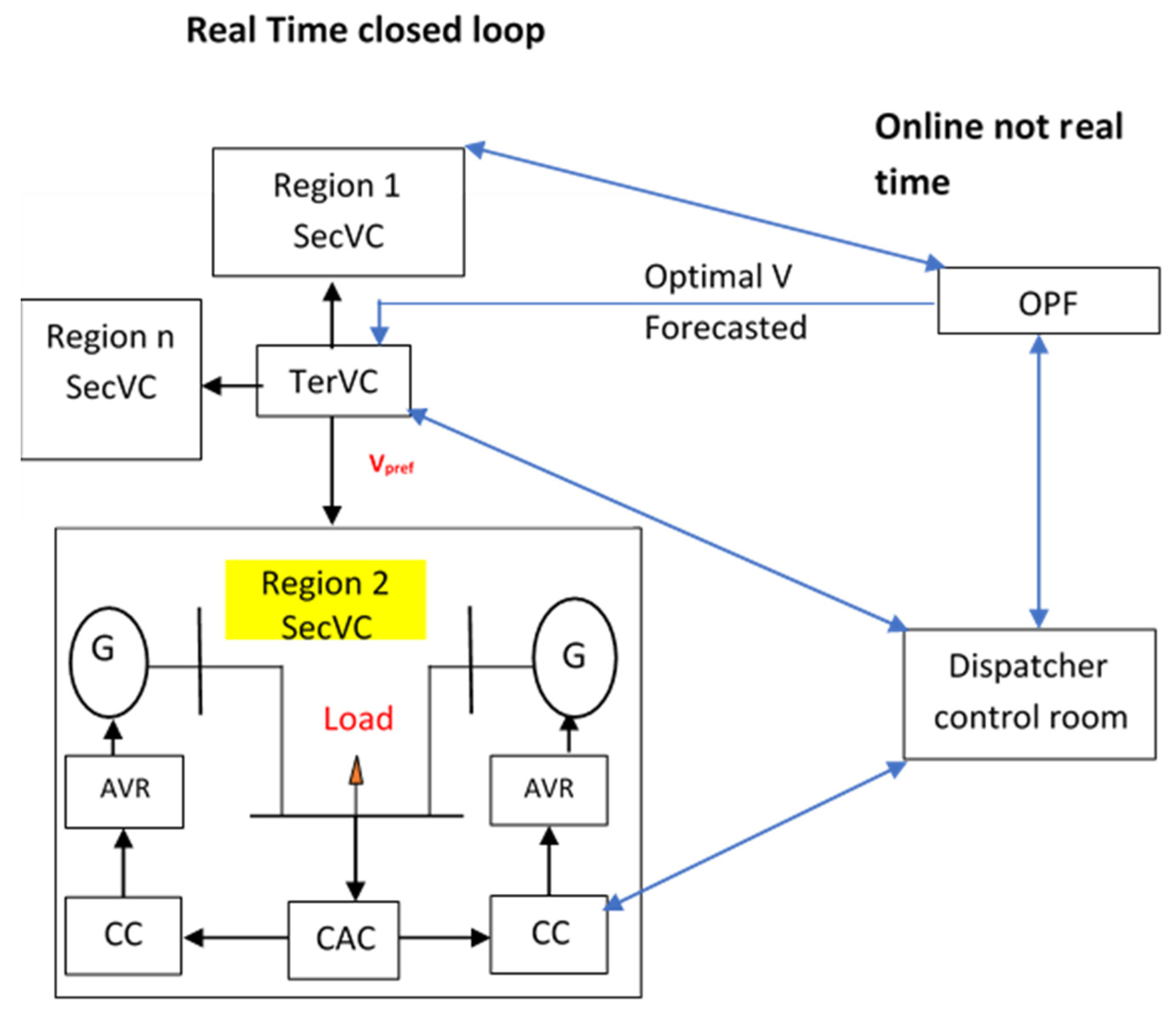
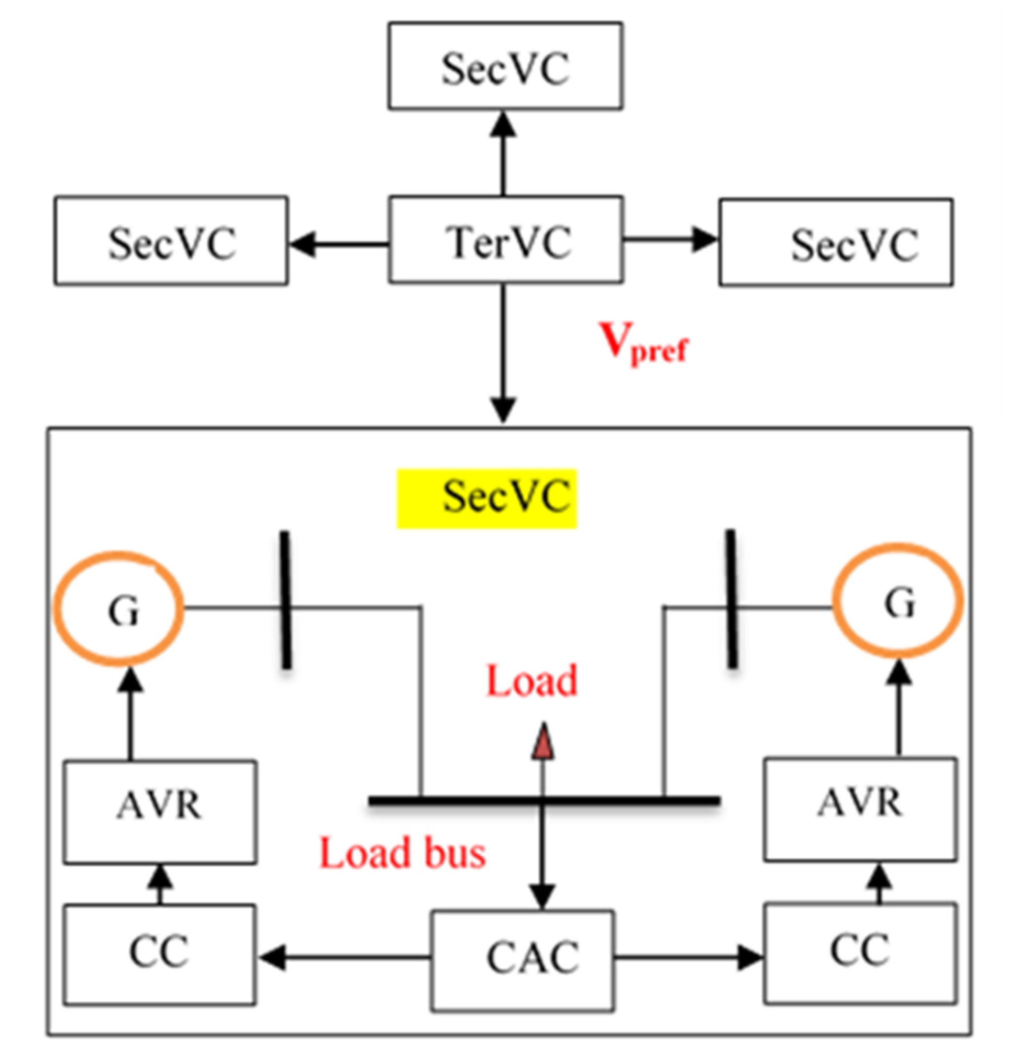
Controlling the voltage of the power grids is performed through three hierarchical control levels: primary voltage control (AVR), secondary voltage control (SecVC) and tertiary voltage control (TerVC) [
4,
5]. The AVR aims to regulate the power station voltage magnitude, while secondary voltage control regulates the load buses voltage magnitude. The control is applied by controlling the most influencing bus voltage, which is called pilot bus [
6]. The tertiary voltage control adjusts the setting value of the pilot bus based on optimal power flow. The technical, economic and social benefits from applying tertiary and secondary voltage control were discussed in [
3].
The idea of voltage control levels was first established in France and Italy, with some limitations; then, it was propagated among European countries and next in the United States, Brazil and, after that, in Asia and Africa. Each country implements the control levels in their own certain way, which is enough to improve the voltage stability and better manage the reactive power resources in the country’s electrical network [
7,
8,
9]. The application of a secondary voltage control scheme is basically dependent on system partitioning and pilot bus selection [
10,
11]. In this paper, the graph theory is used for system partitioning based on [
12]. The pilot buses selection was made using sensitivity analysis for each partition. In [
12], the authors did not apply different control schemes on the power system to improve the voltage.
Nowadays, the use of artificial intelligence is growing rapidly in power system applications, including genetic algorithms, fuzzy logic, look up tables, neural networks, etc. The intelligent facilities have shown a clear development in load forecasting, load frequency control and automatic voltage regulation [
13].
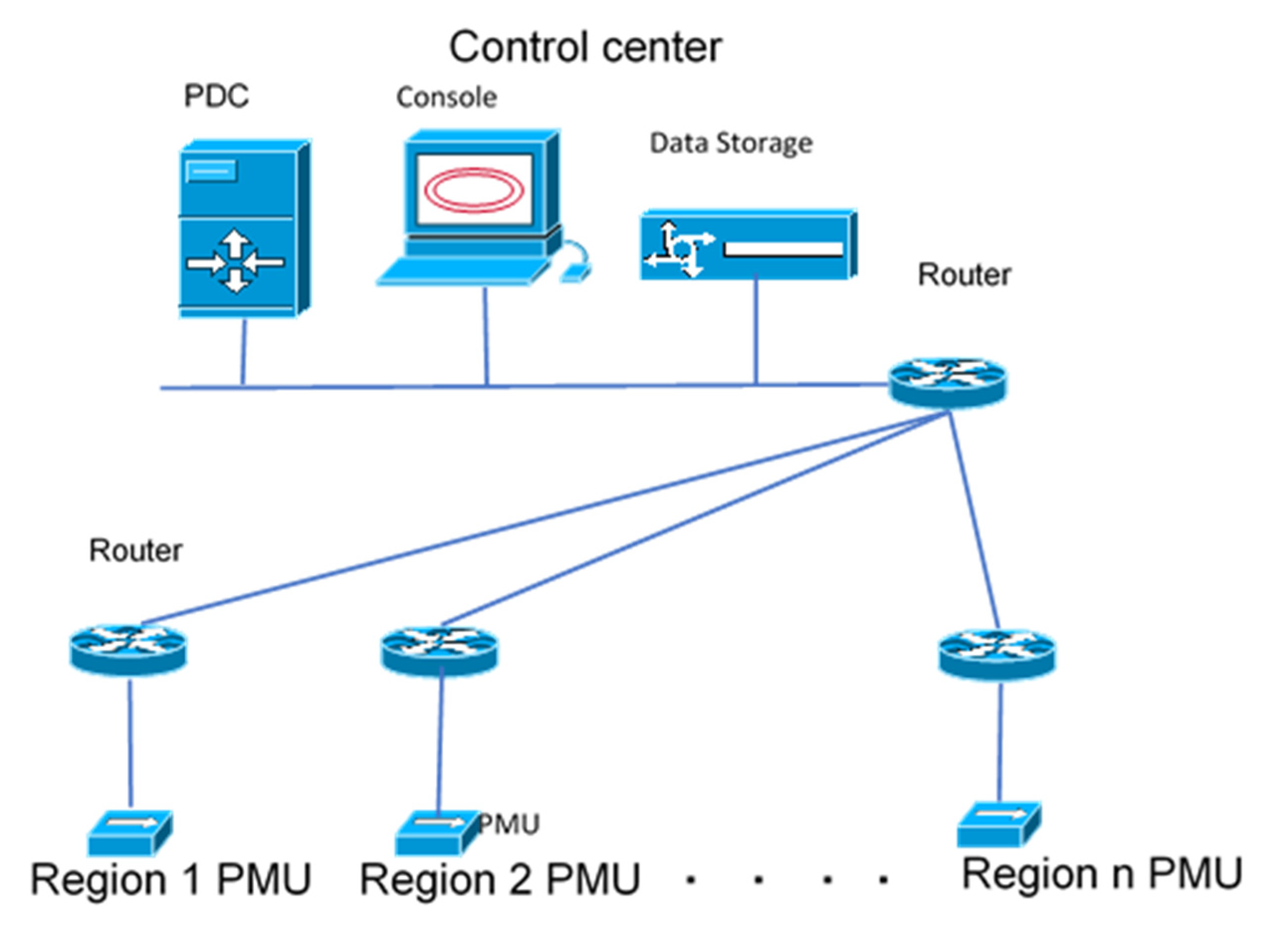
The point-to-point connection, which was applied in most of the power grids worldwide in the last century, is not enough to reach smart grid features. To reach real-time control and real-time protection in the power system a better estimation of its state is highly important. Nowadays, many countries have started to convert the conventional measurements to phasor ones by configuration of wide area measurement systems [
12]. The previous research focused on application of several optimization methods to minimize the number of phasor measurement units (PMUs) while keeping complete observability of the power system due to its high cost [
14,
15]. In [
15], the authors targeted a full wide area measurement system (WAMS) configuration in order to apply SecVC, but in this paper, the optimal placement of PMUs was performed to apply secondary and tertiary voltage control only.
The study of [
2] presented secondary voltage control based on genetic algorithm (GA), the study was applied in the IEEE 14-bus system, which was considered as a single region power system. The results show the effectiveness of the GA proportional integral derivative (PID) secondary voltage control. The authors in [
2] did not consider WAMS and power system partitioning in their application.
The study of [
16] presented secondary voltage control based on GA, the study was applied in a 14-bus system, which was considered as a single region power system, but included only renewable energies.
In [
17], the authors presented secondary voltage control based on Synchrophasor and they improved the voltage profile, but they did not catch the optimal voltage values based on power system optimization at different operating conditions.
In [
18], the authors presented WAMS-based methodology for secondary voltage control. They improved the voltage profile, but they did not consider the change of the optimal load bus voltage at each operation condition.
In [
19], the authors targeted the application of regional optimal power flow to implement secondary voltage control, but they did not consider the implementation process made by the secondary voltage controllers.
In [
20], the authors applied fuzzy secondary voltage control in IEEE 39 bus system considering small disturbances, but they did not consider large disturbance and optimal power flow results.
The contributions of this research study include:
Design of secondary GA PID and Neural Network Based Genetic Algorithm (NNGA) PID secondary voltage controllers to track the reference pilot bus voltage of a multi-region power system. A comparison between the two controllers in terms of robustness at different power system operating scenarios considering small and large disturbances is presented to ensure better system performance.
Design of optimal wide area measurement system for secondary voltage control based on partitioning for the first time unlike previous papers which apply WAMS configuration on the whole grid to perform secondary voltage control.
Regional PMUs are used to measure the real-time voltage of the pilot bus and detect through what-if-analysis the optimal parameters of the secondary voltage genetic PID controller while using the neural network.
Application of secondary voltage control based on optimal power flow results for each operating condition and the controllers are responsible to track the optimal load buses voltages.
The paper is organized as follows:
Section 2 illustrates the voltage control hierarchy using wide area measurement system;
Section 3 includes the power system description;
Section 4 illustrates how the system is divided into regions;
Section 5 illustrates how pilot buses were selected;
Section 6 discusses the application of tertiary voltage control;
Section 7 illustrates the application of secondary voltage control;
Section 8 illustrates how optimal PMUs are placed to apply secondary voltage control only;
Section 9 illustrates how genetic controllers and neural network were designed;
Section 10 presents the simulation results; and
Section 11 summarizes the main conclusions of the paper.
4. Power System Partitioning
In large power systems, to apply SecVC, the grid should be partitioned into regions; then, a pilot bus is selected for each region.
The power system partitioning for secondary voltage control is mainly dependent on two main factors, which are the upgrade of the power system and the dependence of these areas with power system operation condition. Generally, the partitioning aims to avoid the interaction between regions in terms of reactive power exchange and closed loop overlap.
Many researchers proposed different techniques for system partitioning [
10], which are:
- (a)
partitioning based on geographical regions (applied to real grids);
- (b)
partitioning methods based on electrical distance;
- (c)
heuristic and meta-heuristic partitioning methods;
- (d)
partitioning methods based on graph theory;
- (e)
partitioning methods based on learning approach;
- (f)
partitioning based on hybrid approach.
The researchers in [
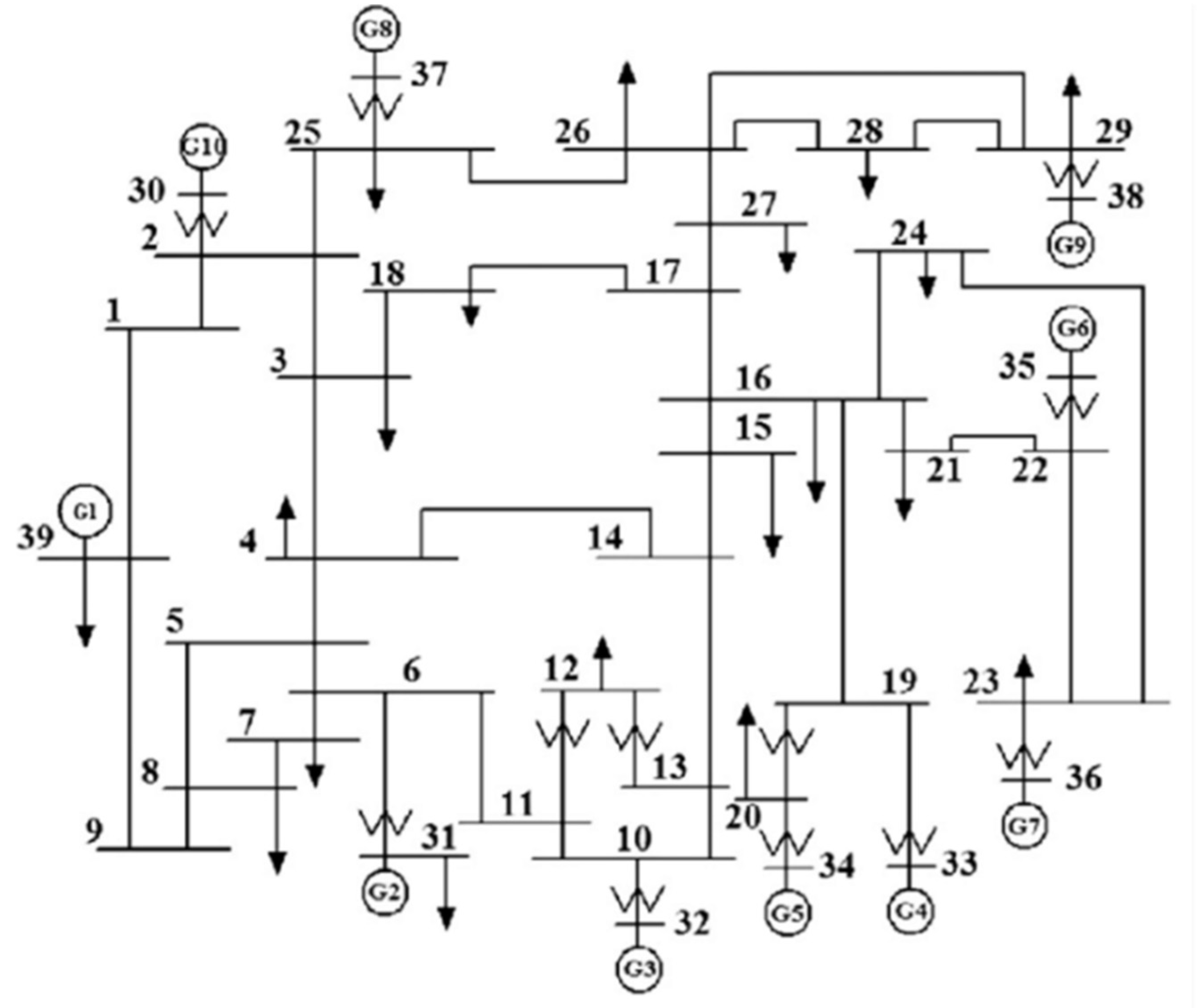
10] compared between those techniques on the IEEE 39 bus system and the results indicated that partitioning based on graph theory drives the system to better performance.
The partitioning matrix is the solution of the graph theory method, such that the ith column has the graph buses that belong to the ith partition. This partition matrix minimizes the objective function Equation (1),
The apparent power between bus number i and bus number j (), where i and j range from 1 to 39 in the IEEE 39 bus system, such that i ǂ j; belongs to different regions representing the weights of the lines cut by regions.
The optimization result of the partitioning process is subjected to a condition that each partition should include one generator (reactive power source), at least, to generate or consume reactive power as part of voltage control of the buses in each partition. The graph theory partitioning method is applied to the IEEE 39 bus system and the results show that the system can be partitioned into six regions, as illustrated in
Table 1, as part of the minimization process, which stated in Equation (1).
5. Pilot Bus Selection
To implement secondary voltage control, a linearization is required. Three alternatives can be used to describe the relation between changes of voltages and (active and reactive) power variations as a requirement of linearization, which are [
23]:
- (1)
Solving power flow based on fast decoupled method, which relates voltage and reactive power variations relation based on sensitivity matrix and is made equal to the negative nodal susceptance matrix of the whole system.
- (2)
To consider the active power flows in the electric network, a detailed model was used, but neglects the effect of active power changes on voltage magnitudes. The detailed model is used in this study to linearize the IEEE 39 bus system, and it was also used in [
23] to linearize the Egyptian power system.
- (3)
The exact model which considers the effect of both active and reactive powers variations on the voltage.
where
is the change of voltage control bus voltage;
is the change of load bus voltage;
is the change of generated reactive power; while
is the change of load reactive power, knowing that
SGG,
SGL, SLG and
SLL, are submatrices that represent the relation between a change of voltage with a change of reactive power.
From Equation (2), it is found that:
in Equation (3) is the inverse of submatrix; while B is a negative multiplication between inverse of submatrix and submatrix.
Since the control should be applied to certain load buses, these are called pilot buses. The control of those pilot buses should keep the voltage stability and performance in the whole system.
M is a binary matrix (0 or 1) with a size (nP × nL) to indicate which load buses are pilot buses; nP is the number of pilot buses while nL is the number of load buses in the system.
The pilot buses were selected in each region by calculating the sensitivity matrix of the system and the load bus with the highest sensitivity factor
in each region was selected to be a pilot bus [
10,
11].
Table 2 illustrates the pilot bus of each region which has the highest
among the load buses of the region, because this means that this load bus voltage change is the most sensitive one to the reactive power changes and if it reaches optimal solution; the remaining load buses are optimally operated in terms of voltage magnitude. In fact, theoretically, for each operation condition, the pilot bus of the region may differ; however, to implement SecVC practically, since equipment of measurement and control is required, a one pilot bus is selected based on the
of the normal operating conditions.
9. Secondary Voltage Controllers Design
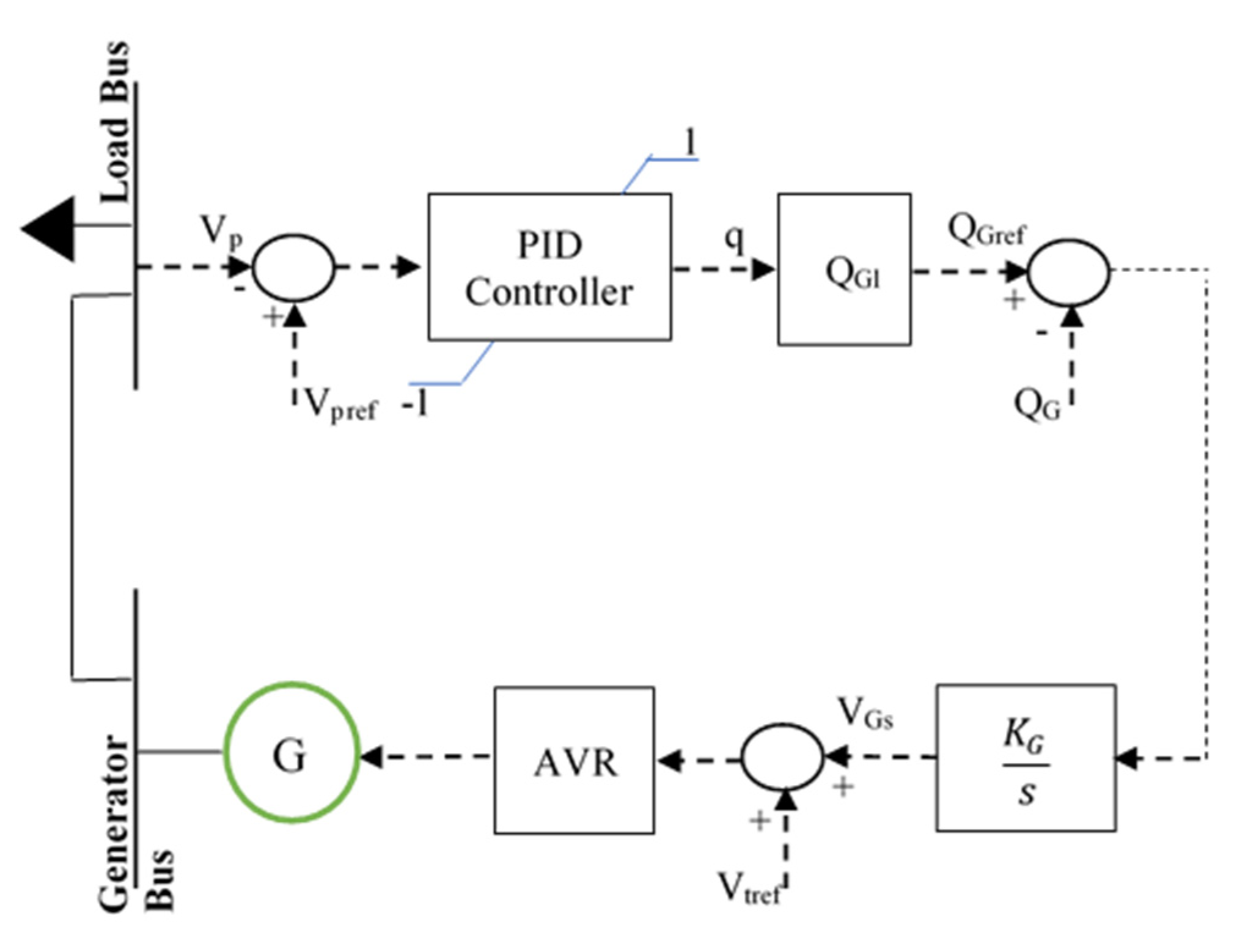
Since one of the main features of smart grid is self-healing, which requires a real-time optimal control at different power grid operating conditions, artificial intelligence is the key to implement this feature. In this paper, the secondary voltage control was applied by a genetic PID controller, instead of the conventional one, the parameters of which were selected through mathematical local minimization or trial and error.
9.1. Genetic Secondary PID Controller
The design of PID controllers will be performed for each operation condition separately, using the genetic algorithm (GA) toolbox in MATLAB to enable the pilot bus to reach its optimal value at this condition. The optimization problem is described as follows:
Objective function: minimizing integration of square error ()
Variables: PID controller parameters (, and ).
Constraints: q limits (±100%) and generated reactive power limits.
The GA is an iterative optimization technique, working with a number of candidate solutions (known as a population). In many engineering problems, the initial start of GA begins its search with a random population of solutions [
25]. GA is available in MATLAB and the parameters are set such that the population type is double vector while the population size of 20. The crossover fraction is set to be 0.8, while the elite count reproduction is 2. To reduce the possibility of reaching local minima, instead of global one, mutation rate is increased and the optimization process is repeated using the optimal solution as the initial one [
26].
9.2. Neural Network Based on Genetic Secondary PID Controller
An artificial neural network (ANN) is a group of neurons in the form of simple processing units that are linked to each other to obtain a behaviour that is like human behaviour when solving an engineering problem [
27].
Many research papers have presented studies in voltage stability and control based on ANN. In [
28], the study presented an application of ANN for monitoring power system voltage stability, while in [
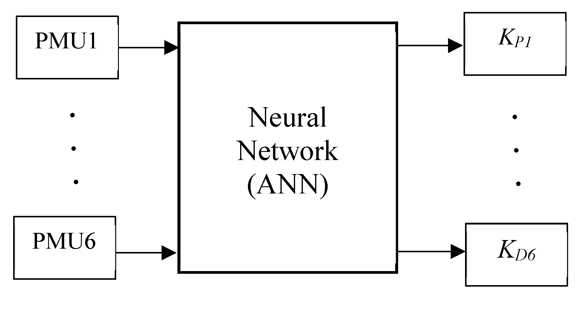
29], the study proposed and used ANN to help the dispatcher reach an optimal decision during contingencies. ANN is used in the static voltage stability to instantaneously map a contingency to a set of controllers where the types, locations and amount of switching can be induced. In this study, a design for the secondary voltage PID controller of each region is proposed. The system is then assumed to be subjected to different contingencies and disturbances to examine the controller’s performance. An artificial intelligence facility (ANN) is used to select the optimal parameters of the secondary voltage PID controllers at each operation condition. The PMU readings of the voltage magnitudes of the pilot buses will be the input to the neural network, which will decide the optimal values of the PID designed for the specific contingencies, as shown in
Figure 8. The ANN used in this work has 6 inputs, due to the presence of 6 PMUs—so18 outputs (which are the secondary PID controllers’ parameters, since there are 6 partitions, so there are 6 controllers, and each one has 3 parameters, meaning a total 18 outputs)—and the ANN includes a 10-neurons hidden network. The network is designed and trained using the Levenberg–Marquardt backpropagation method [
2,
30].


