Proceeding Paper

In Silico Analysis of Microfluidic Systems for the Purification of Magnetoliposomes †

1
Department of Biomedical Engineering, Universidad de los Andes, Cra. 1E No. 19a-40, Bogotá 111711, DC, Colombia
2
Department of Electrical and Electronic Engineering, Universidad de los Andes, Cra. 1E No. 19a-40, Bogotá 111711, DC, Colombia
3
Department of Food and Chemical Engineering, Universidad de los Andes, Cra. 1E No. 19a-40, Bogotá 111711, DC, Colombia
4
School of Chemical Engineering and Advanced Materials, The University of Adelaide, Adelaide, SA 5005, Australia
*
Author to whom correspondence should be addressed.
Presented at the 2nd International Online-Conference on Nanomaterials, 15–30 November 2020; Available online: https://iocn2020.sciforum.net/.
Mater. Proc. 2021, 4(1), 73; https://doi.org/10.3390/IOCN2020-07794
Published: 15 November 2020
(This article belongs to the Proceedings of The 2nd International Online-Conference on Nanomaterials)

Abstract

:
Magnetite nanoparticles (MNPs) have been considered for several applications in drug delivery. However, the main challenge is to assure high cell-penetration levels, especially when dealing with cargoes that show limited membrane passing. A strategy is to encapsulate the MNPs into liposomes to form magnetoliposomes (MLs) capable of fusing with membranes to achieve high delivery rates. MLs have therefore been used as carriers in the biomedical field due to their ability to release active molecules that can be used in treatments of diverse diseases. There are several techniques to produce such encapsulates, however, the main challenge is that the process often leads to an important fraction of non-encapsulated MNPs. Purification of such a fraction is challenging because of the small size difference between the particles and the MLs and the reduced magnetic responsiveness. Seeking to obtain pure MLs with potential use in the medical field, the following study presents finite element simulations using COMSOL Multiphysics of two purification methods. Accordingly, we implemented the magnetic and asymmetric pinched flow fractionation (AsPFF) separation systems to evaluate their purification efficiencies considering operation parameters such as the Flow Rate Ratio (FRR) and Total Velocity Ratio (TVR). Additionally, a mixture interaction approach was used to model the MNPs as a dispersed ferrofluid phase. This was compared with a particle tracing approach where MNPs are considered individual entities subjected to hydrodynamic forces. The results show efficiencies between 60% and 90% for both separation methods, which confirms their feasibility to improve and optimize the purification of MLs in a high throughput manner.

Published: 15 November 2020

1. Introduction

Liposomes with embedded magnetite nanoparticles (MNPs), called magnetoliposomes (MLs), have been extensively used as carriers for potential applications in the pharmaceutical industry [1]. These encapsulating platforms have been studied for their ability to release various active therapeutic molecules at a given action site without the need for molecular targeting agents. As a result, MLs have enabled various potential therapeutic strategies for conditions ranging from Parkinson’s disease to cancer [2,3]. This ample range of applications could be attributed to the suitability of the contained MNPs as contrast agents, drug delivery vehicles and enablers of localized hyperthermia upon magnetic stimulation [1,4,5]. Over the past few years, several techniques have been proposed for the preparation of MLs, in which MNPs can be encapsulated in the aqueous lumen, embedded in the lipid bilayer or conjugated on the surface of the liposomes [5,6,7,8]. Despite the progress, these methods pose some challenges, including the relatively large particle size distribution, heterogeneous morphology and, most importantly, the difficulty in separating the non-encapsulated/unbound MNPs [9]. Recent reports have demonstrated that these issues can be addressed through more precise control of assembly conditions at the microscale via microfluidic devices [10,11].
In this regard, microfluidic systems have enabled the massive production of MLs with more homogeneous physicochemical, uniform size distribution, high loading efficiencies and reduced costs [4,10,11]. Despite the significant advances in the synthesis and liposomal encapsulation technologies (LET) provided by microfluidics, proper separation methods are still a major challenge. This can be explained by the small size differences between the MLs and the non-encapsulated nanoparticles [12]. The absence of robust protocols to obtain high-purity MLs has significantly limited their possible application at the clinical scale [13]. A possible avenue to tackle this hurdle is through the precise and dynamic adjustment of magnetic gradients to retain excess MNPs without compromising the integrity of the MLs. Magnetic separation technologies have seen a significant advance over the past decade, mainly due to their applicability, versatility and ease of implementation in many areas of medical biosciences, including cell sorting, disease diagnostics and therapeutics [14,15,16]. These applications have been enabled by advanced instrumentation that combines superconducting magnets and filters consisting of ferromagnetic particles, which have the primary goal of enhancing the intensity and gradient of imposed magnetic fields [17,18]. This is critical to ensure that magnetoforetic forces dominate over hydrodynamic forces, especially for nanoscale objects (10–20 nm), where fine spatial control over magnetic forces considerably decline [17]. Despite the progress, the proposed instruments and devices have not been fully characterized and entail certain impediments regarding scalability [17,18]. A separate strategy to facilitate continuous size separation of particles is the pinched flow fractionation devices and, in particular, the asymmetric ones (AsPFF). This approach is based on the unique behavior of fluids within pinched segments of microfluidic systems where particle positions can be manipulated effectively. This is amplified at the end of the pinched segment, causing the particles’ separation and their recovery in different branches or outlets of the system [12].
Here, we explored two different methods for the purification of suspensions of MLs and free MNPs via microfluidic systems. The first method relies on the application of magnetic fields directly to highly concentrated suspensions of MNPs (modeled as ferromagnetic fluids) mostly under laminar conditions given the use of microliter scale volumes enclosed within the microfluidic device’s microchannels [19,20]. The second method introduces a passive pressure-driven microsystem whose particle separation principle is based on hydraulic resistance differences for several channels branching out from a pinched segment [12]. The proposed methods’ performance and feasibility were studied in silico via multiphysics simulations implemented in COMSOL Multiphysics® by coupling the particle tracing and mixture model physics.

2. Materials and Methods

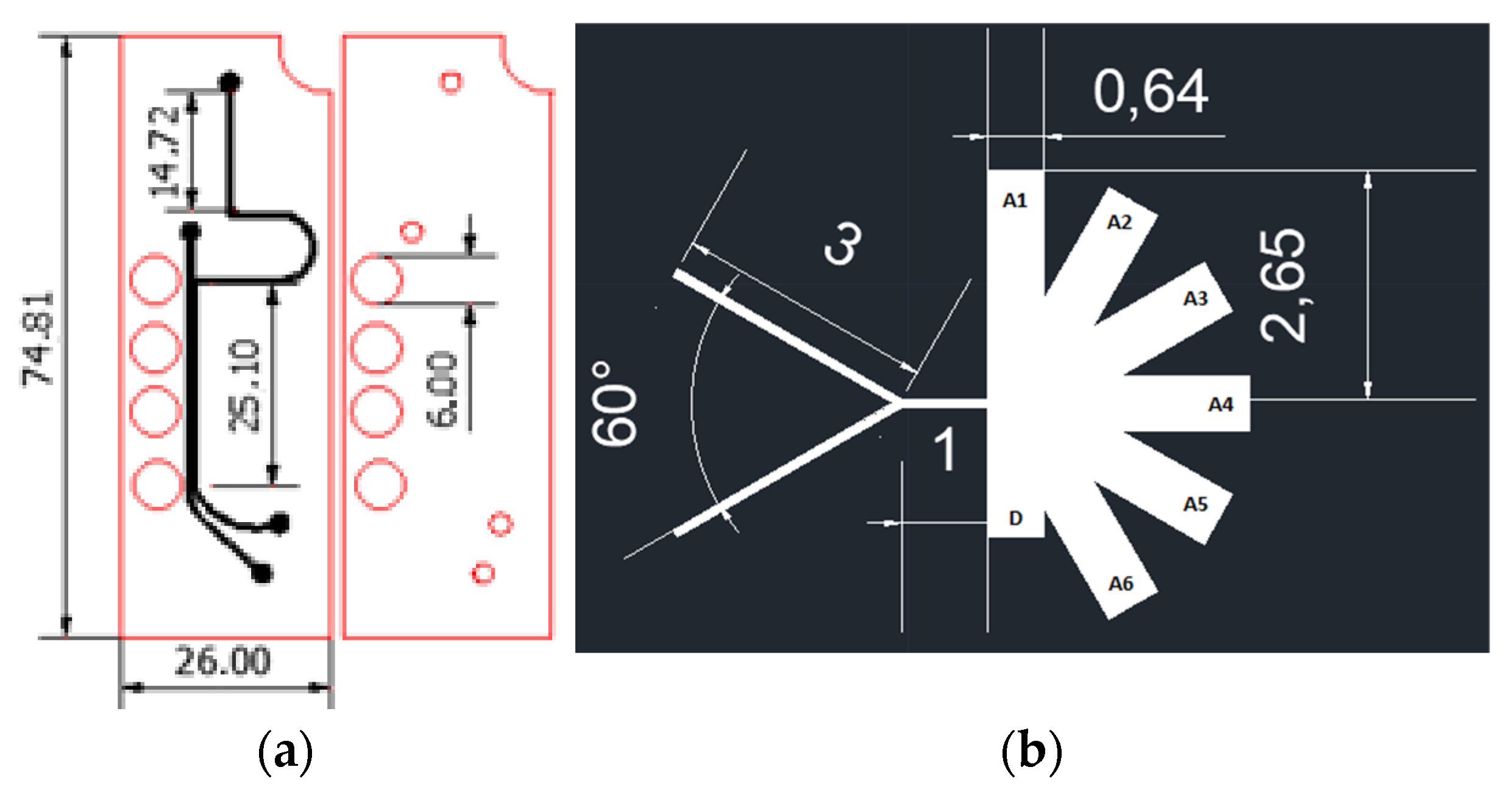
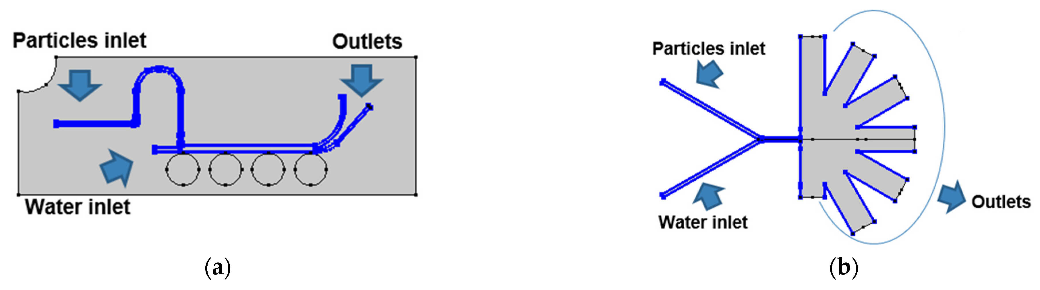
2.1. Microfluidic Systems Design

2.2. Simulation

The multiphysics simulations were carried out in the software COMSOL Multiphysics® by implementing the particle tracing module and the mixture model, laminar flow for the two designs presented above (Figure 1).

2.2.1. Particle Tracing Model

The fluid flow was considered under laminar flow regime, whose governing Equations (1) and (2):
[ P I + μ ( u + ( u ) ) ] + F = 0
ρ ( u ) = 0
where P is the pressure, µ is the fluid’s dynamic viscosity, F the volumetric forces, u is the velocity and ρ is the fluid density. Particle transport was modeled with a particle tracing module, according to which Newton’s second law governs the movement of the particles (3):
d ( m P v ) d t = F t
where m P is the particles mass, v the velocity and F t is the sum of all forces acting on the particles. For the magnetic separation system, the particles’ forces were the drag force (4) and the magnetic force, which is dependent on the magnetic flux density distribution imposed by the applied magnetic field physic (7). In the case of the AsPFF separation system, the involved forces were the drag force defined in (4) and the lift force in the pinched segment (8).
F D = 1 τ P m P ( u v )
τ p = ρ P d p 2 18 μ
F D = V M Δ X μ 0 ( B · Δ ) B
where Δ X is the magnetic susceptibility difference between the particle and the fluid,   V M   is the scalar magnetic potential, B is the magnetic flux density distribution defined in (7) and μ0 is the vacuum permeability.
B = μ 0 μ r H + B r
where H   is the Magnetic field distribution,   μ 0 and   μ r the vacuum permeability and relative permeability and B r the remanent flux density, which in this case, was established as 1 T.
F L = ρ r P 4 β ( β G 1 ( s ) + γ G 2 ( s ) ) n
β = | D ( n ) u |
γ = | D 2 2 ( n ) 2 4 |
u | | = ( 1 n n ) u
where ρ is the particle density, r P is the particle radius, D is the width between the walls, s is the normalized distance to the first parallel boundary and n is the unit vector from the nearest point on the first boundary defined in the pinched segment’s walls.
Boundary Conditions and Simulation Features for Particle Tracing Simulations
For the magnetic separation system, the laminar flow and the magnetic field physics were carried out in a stationary study with a mesh composed of 26,034 domain elements and 1384 boundary elements for the computational domain. Additionally, a bi-directionally coupled particle tracing with the multifrontal massively parallel sparse direct Solver (MUMPS) was used for the particle tracing module with 1500 particles per component (i.e., NPs or MLs) with 49,476 domain elements and 3075 boundary elements for the microfluidic channels. The boundary conditions used for this module were the lift force in the microfluidic channels’ walls, the drag force in all the microfluidic system domain and the upper inlet as the main entrance for the particles into the system (Figure 2a). For the AsPFF separation system, the laminar flow simulation was carried out in a stationary study. Simultaneously, a bi-directionally coupled particle tracing with 1500 particles per component was used with a mesh composed of 27,216 domain elements and 1575 boundary elements. The boundary conditions for this system are shown in Figure 2b.

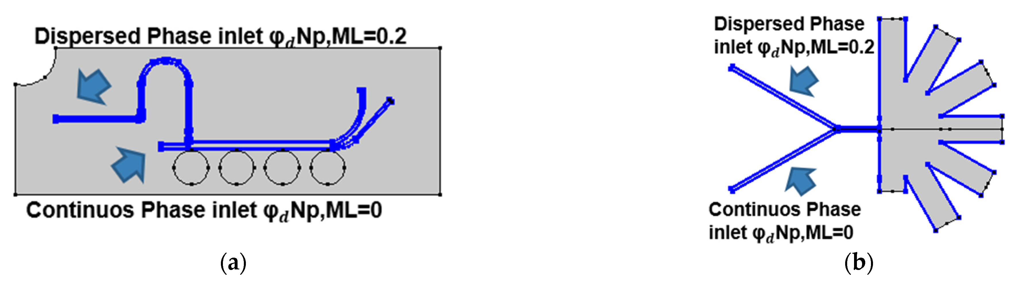
2.2.2. Mixture Model

The ferrofluid (MNps and MLs) was simulated by implementing a mixture model, laminar flow physic, for both microfluidic separation approaches. The interface solves a set of the Navier stokes equations for the momentum of the mixture. The pressure distribution is calculated from a mixture averaged continuity equation, and the velocity of the dispersed phase is described by a slip model [21]. The momentum conservation equation and the continuity equation are presented below in (12) and (13), respectively:
ρ d u d t + ρ ( u ) u = [ p l + μ ( u + ( u ) T 2 3 ( u ) ) ] [ ρ C d ( 1   C d ) U s l i p U S l i p T ] + F
( ρ c ρ d ) { [ ϕ d ( 1 c d ) u s l i p ] + m d c ρ d } + ρ c ( u ) = 0
where P is the pressure, µ is the dynamic viscosity of the fluid, ρ c ,   ρ d the continuous and dispersed phase densities, ϕ d is the volume fraction of the dispersed phase,   m d c the turbulent dispersed phase diffusion and F the body forces, which for the case of magnetic separation is described by the kelvin body force due to a spatially non-uniform magnetic field, as described by (14) [22]
F = ( M ) B
Boundary Conditions and Simulation Features for Mixture Model Simulations
Figure 3 presents the boundary conditions used for the mixture model simulations for both separation approaches. In both cases, the time-dependent simulations were carried out with a value of 0.2 for the dispersed phase volume fraction of each particle component and the MUMPS solver.

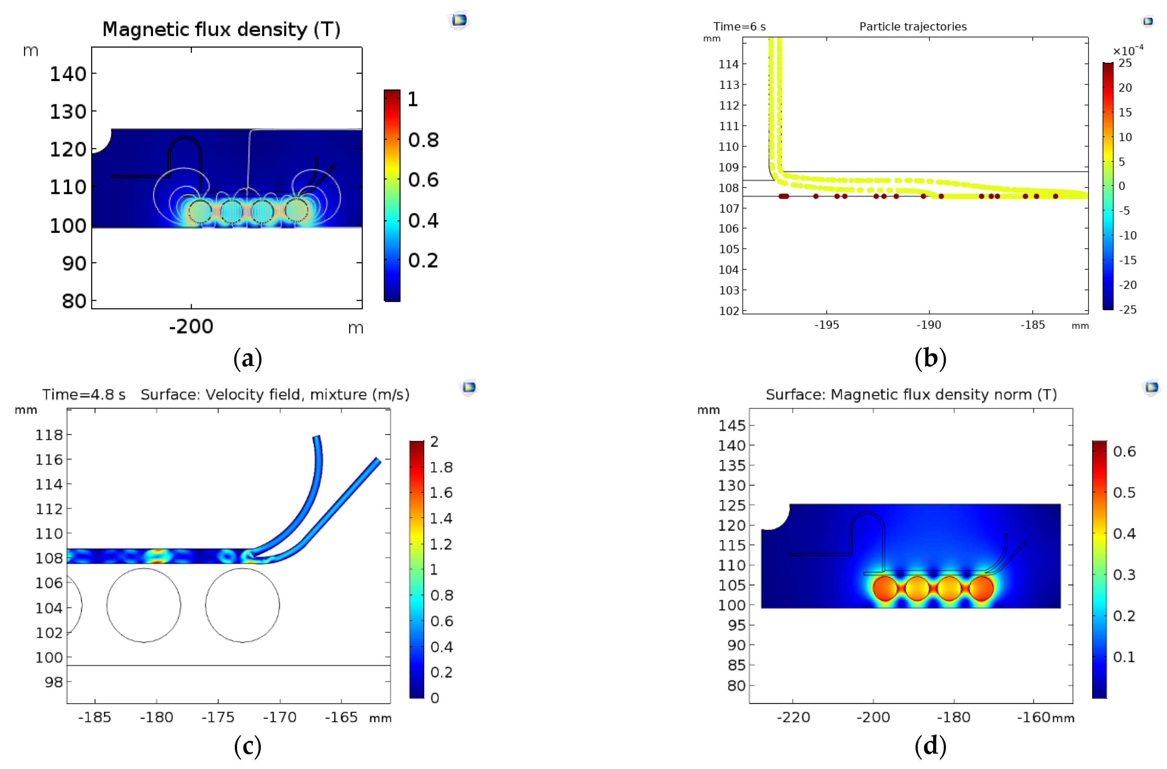
3. Results and Discussion

Figure 4 shows the magnetic separation system results with the two simulation approaches (Particle tracing and mixture model). In the particle tracing results (Figure 4a,b), the separation efficiencies are greater than 90% with an FRR of 1:1 and a TVR of 0.001 (m/s). Despite the high separation efficiency, the simulations show that this could be attributed to particles stuck at the channel wall near the magnetic field’s highest intensity. This impacts not only NPs but also the MLs, which results in only collecting a small volume of purified samples. The mixture model simulation also shows that sections of the channel with higher magnetic flux densities exhibit the highest changes in the mixture velocities (Figure 4c,d). This indicates a high separation performance.
Finally, the AsPFF separation results are presented in Figure 5. According to the particle tracing simulations, the separation performance of the system is shown in Figure 5a,b. In this case, the separation efficiency approached 86% with the highest number of purified MLs in the drainage outlet (D), which exhibits the least hydraulic resistance. In contrast, the mixture model predicts a separation efficiency of about 65% under a TVR of 0.0025 m/s and an FRR of 1:50 (Dispersed:Continuous). Figure 5d shows that the highest purification level for MLs is achieved at the A1 outlet, which is in front of D, the outlet with the best performance according to the particle tracing model. These results agree well with those put forward by Tagaki et al. [12] for a system with ours’ dimensions. This strongly suggests that the mixture model might produce more accurate results for the system and particle sizes of interest for us.
Despite the contrasting results of the two implemented models, they provide complementary qualitative and quantitative information of the hydrodynamics and particle transport within the system, which is valuable to move to prototyping and testing. For future work, we are planning to run more comprehensive parametric studies to identify the conditions for optimal separation such that we maximize the amount of pure MLs collected. In addition, we expect to manufacture and test the devices by low-cost manufacturing via laser cutting of polymethyl methacrylate (PMMA) sheets [23].

Author Contributions

Conceptualization, J.C.C., J.F.O. and L.H.R.; Methodology, data curation and data analysis C.E.T., A.A. and J.C.C.; Formal analysis and investigation, C.E.T. and A.A.; Validation, J.C.C., J.F.O. and L.H.R.; Writing—original draft preparation, C.E.T. and A.A.; Writing—review and editing, J.C.C., J.F.O. and L.H.R.; Supervision, J.C.C., J.F.O. and L.H.R. All authors have read and agreed to the published version of the manuscript.

Funding

This work was funded by the Colombian Ministry of Science, Technology and Innovation (Minciencias) Grants 689-2018 and ID 120380763212—PPTA # 8352.

Acknowledgments

The authors would like to thank the Department of Biomedical Engineering, Food and Chemical engineering and the Department of Electrical and Electronics Engineering at Universidad de los Andes for the financial and technical support.

Conflicts of Interest

The authors declare no conflict of interest.

References

  1. Choi, W.I.; Sahu, A.; Wurm, F.R.; Jo, S.M. Magnetoliposomes with size controllable insertion of magnetic nanoparticles for efficient targeting of cancer cells. RSC Adv. 2019, 9, 15053–15060. [Google Scholar] [CrossRef] [PubMed]
  2. Wu, Y.; Lu, Z.; Li, Y.; Yang, J.; Zhang, X. Surface modification of iron oxide-based magnetic nanoparticles for cerebral theranostics: Application and prospection. Nanomaterials 2020, 10, 1–21. [Google Scholar] [CrossRef] [PubMed]
  3. De Jesus, P.D.C.C.; Pellosi, D.S.; Tedesco, A.C. Magnetic Nanoparticles: Applications in Biomedical Processes as Synergic Drug-Delivery Systems; Elsevier Inc.: Amsterdam, The Netherlands, 2019. [Google Scholar]
  4. Conde, A.J.; Batalla, M.; Cerda, B.; Mykhaylyk, O.; Plank, C.; Podhajcer, O.; Cabaleiro, J.M.; Madrid, R.E.; Policastro, L. Continuous flow generation of magnetoliposomes in a low-cost portable microfluidic platform. Lab Chip 2014, 14, 4506–4512. [Google Scholar] [CrossRef] [PubMed]
  5. Rodrigues, A.R.O.; Almeida, B.G.; Araújo, J.P.; Queiroz, M.J.R.P.; Coutinho, P.J.G.; Castanheira, E.M.S. Magnetoliposomes for dual cancer therapy. In Inorganic Frameworks as Smart Nanomedicines; William Andrew Publishing: Norwich, NY, USA, 2018. [Google Scholar]
  6. Rodrigues, A.R.O.; Gomes, I.T.; Almeida, B.G.; Araújo, J.P.; Castanheira, E.M.S.; Coutinho, P.J.G. Magnetoliposomes based on nickel/silica core/shell nanoparticles: Synthesis and characterization. Mater. Chem. Phys. 2014, 148, 978–987. [Google Scholar] [CrossRef]
  7. Bonnaud, C.; Monnier, C.A.; Demurtas, D.; Jud, C.; Vanhecke, D.; Montet, X.; Hovius, R.; Lattuada, M.; Rothen-Rutishauser, B.; Petri-Fink, A. Insertion of nanoparticle clusters into vesicle bilayers. ACS Nano 2014, 8, 3451–3460. [Google Scholar] [CrossRef] [PubMed]
  8. Floris, A.; Ardu, A.; Musinu, A.; Piccaluga, G.; Fadda, A.M.; Sinico, C.; Cannas, C. SPION@liposomes hybrid nanoarchitectures with high density SPION association. Soft Matter 2011, 7, 6239–6247. [Google Scholar] [CrossRef]
  9. Mota-Cobián, A.; Velasco, C.; Mateo, J. Optimization of purification techniques for lumen-loaded magnetoliposomes. Nanotechnology 2020, 31, 145102. [Google Scholar] [CrossRef] [PubMed]
  10. Joshi, S.; Hussain, M.T.; Roces, C.B.; Anderluzzi, G.; Kastner, E.; Salmaso, S.; Kirby, D.J.; Perrie, Y. Microfluidics based manufacture of liposomes simultaneously entrapping hydrophilic and lipophilic drugs. Int. J. Pharm. 2016, 514, 160–168. [Google Scholar] [CrossRef] [PubMed]
  11. Al-Ahmady, Z.S.; Donno, R.; Gennari, A.; Prestat, E.; Marotta, R.; Mironov, A.; Newman, L.; Lawrence, M.J.; Tirelli, N.; Ashford, M.; et al. Enhanced Intraliposomal Metallic Nanoparticle Payload Capacity Using Microfluidic-Assisted Self-Assembly. Langmuir 2019, 35, 13318–13331. [Google Scholar] [CrossRef] [PubMed]
  12. Takagi, J.; Yamada, M.; Yasuda, M.; Seki, M. Continuous particle separation in a microchannel having asymmetrically arranged multiple branches. Lab Chip 2005, 5, 778–784. [Google Scholar] [CrossRef] [PubMed]
  13. Monteiro, N.; Martins, A.; Reis, R.L.; Neves, N.M. Liposomes in tissue engineering and regenerative medicine. J. R. Soc. Interface 2014, 11. [Google Scholar] [CrossRef] [PubMed]
  14. Kye, H.G.; Park, B.S.; Lee, J.M.; Song, M.G.; Song, H.G.; Ahrberg, C.D.; Chung, B.G. Dual-neodymium magnet-based microfluidic separation device. Sci. Rep. 2019, 9, 1–10. [Google Scholar] [CrossRef] [PubMed]
  15. Khashan, S.A.; Dagher, S.; Alazzam, A.; Mathew, B.; Hilal-Alnaqbi, A. Microdevice for continuous flow magnetic separation for bioengineering applications. J. Micromech. Microeng. 2017, 27. [Google Scholar] [CrossRef]
  16. Guo, J.; Lin, L.; Zhao, K.; Song, Y.; Huang, M.; Zhu, Z.; Zhou, L.; Yang, C. Auto-affitech: An automated ligand binding affinity evaluation platform using digital microfluidics with a bidirectional magnetic separation method. Lab Chip 2020, 20, 1577–1585. [Google Scholar] [CrossRef] [PubMed]
  17. Nakao, R.; Matuo, Y.; Mishima, F.; Taguchi, T.; Maenosono, S.; Nishijima, S. Development of magnetic separation system of magnetoliposomes. Phys. C Supercond. Appl. 2009, 469, 1840–1844. [Google Scholar] [CrossRef]
  18. Amiri, M.; Salavati-Niasari, M.; Akbari, A. Magnetic nanocarriers: Evolution of spinel ferrites for medical applications. Adv. Colloid Interface Sci. 2019, 265, 29–44. [Google Scholar] [CrossRef] [PubMed]
  19. Chakraborty, S.; Kumar, A.; Sen, P. Special Issue on Microfluidics: Theory and Applications. J. Indian Inst. Sci. 2018, 98, 83–84. [Google Scholar] [CrossRef]
  20. Barreto, G.R.; Kawai, C.; Tofanello, A.; Neves, A.A.R.; Araujo-Chaves, J.C.; Belleti, E.; Lanfredi, A.J.C.; Crespilho, F.N.; Nantes-Cardoso, I.L. Magnetoliposomes as model for signal transmission. R. Soc. Open Sci. 2019, 6. [Google Scholar] [CrossRef]
  21. Comsol Multiphysics. Mixer Module. 2015. Available online: http://www.comsol.com/mixer-module (accessed on 10 November 2020).
  22. Bergheau, J.M.; Fortunier, R. Finite Element Simulation of Heat Transfer. Finite Elem. Simul. Heat Transf. 2010. [Google Scholar] [CrossRef]
  23. Campaña, A.L.; Sotelo, D.C.; Oliva, H.A.; Aranguren, A.; Ornelas-Soto, N.; Cruz, J.C.; Osma, J.F. Fabrication and characterization of a low-cost microfluidic system for the manufacture of alginate-lacasse microcapsules. Polymers 2020, 12. [Google Scholar] [CrossRef] [PubMed]
Figure 1. Separation microfluidic system designs (dimensions in mm) (a) Magnetic separation microfluidic system; (b) AsPFF separation microfluidic system.
Materproc 04 00073 g001
Figure 2. Boundary conditions for the particle tracing simulations: (a) magnetic separation microfluidic system where the drag force condition was imposed in all the channels of the computational domain and the lift force on the walls of the microfluidic channels. (b) AsPFF separation microfluidic system where the drag force condition was imposed in all the channels of the computational domain and a lift force condition on the pinched segment.
Materproc 04 00073 g002
Figure 3. Boundary conditions for the mixture model simulations: (a) mixture model in the magnetic separation microfluidic system with a volumetric force defined in all the channels of the computational domain according to (10); (b) mixture model in the AsPFF separation microfluidic system with the inlets for the dispersed phase located in the upper inlet of the system.
Materproc 04 00073 g003
Figure 4. Surface results for the magnetic separation: (a) magnetic flux density (T) changes along with the microfluidic system (b) results of separation by the particle tracing module; NPs (yellow) and MLs (red) Magnetic flux density norm (T) in the microfluidic system (d) mixture velocity profile.
Materproc 04 00073 g004
Figure 5. Results of the AsPFF separation microfluidic system. (a) Pressure distribution along with the system; (b) particle tracing results for NPs (red) and MLs (blue); (c) velocity profile obtained with the mixture model; (d) volume fraction of nanoparticles collected at each outlet.
Materproc 04 00073 g005
Publisher’s Note: MDPI stays neutral with regard to jurisdictional claims in published maps and institutional affiliations.

