Proceeding Paper

Working Fluid Selection for Biogas-Powered Organic Rankine Cycle-Vapor Compression Cycle †

by
Muhammad Talha
*,
Nawaf Mehmood Malik
,
Muhammad Tauseef Nasir
,
Waqas Khalid
,
Muhammad Safdar
and
Khawaja Fahad Iqbal
Department of Mechanical Engineering, School of Mechanical and Manufacturing Engineering (SMME), National University of Sciences and Technology, Islamabad 44000, Pakistan
*
Author to whom correspondence should be addressed.
Presented at the 3rd International Conference on Modern Technologies in Mechanical & Materials Engineering (MTME2025), Topi, Pakistan, 16–17 April 2025.
Mater. Proc. 2025, 23(1), 1; https://doi.org/10.3390/materproc2025023001
Published: 25 July 2025

Abstract

The worldwide need for energy as well as environmental challenges have promoted the creation of sustainable power solutions. The combination of different working fluids is used for an organic Rankine cycle-powered vapor compression cycle (ORC-VCC) to deliver cooling applications. The selection of an appropriate working fluid significantly impacts system performance, efficiency, and environmental impact. The research evaluates possible working fluids to optimize the ORC-VCC system. Firstly, Artificial Neural Network (ANN)-derived models are used for exergy destruction ( E d t o t ) and heat exchanger total heat transfer capacity ( U A t o t ). Later on, multi-objective optimization was carried out using the acquired models for E d t o t and U A t o t using the Genetic Algorithm (GA) followed by the Technique for Order of Preference by Similarity to Ideal Solution (TOPSIS). The optimization results showcase Decane ORC-R600a VCC as the best candidate for the ORC-VCC system; the values of E d t o t and U A t o t were found to be 24.50 kW and 6.71 kW/K, respectively. The research data show how viable it is to implement biogas-driven ORC-VCC systems when providing air conditioning capabilities.

1. Introduction

The world is in peril owing to the persistent and accumulating effects of global warming [1]. Other than that, it has been observed that as the economy of developing countries increases, they tend to consume more fossil fuels, hence also contributing to enhancing environmental concerns [2]. Due to this, it is vital that renewable energy is incorporated [3,4]. There are several renewable energies, such as wind, solar, biomass, geothermal, and hydro sources [5]. Amongst these sources, biomass is feasible in terms of providing a stable operation independent of location-based constraints [5].
Given the above-mentioned concerns, it was declared by Li et al. [6] that during the summer season, about 30–50% of electricity is utilized to provide air conditioning. Therefore, a reduction in electricity consumption in this way could be beneficial for electricity power conservation. Realizing the importance of this concern, several studies have been conducted, and their contributions can be retrieved from the reviewed papers [7,8,9,10].
One solution is the organic Rankine cycle-powered vapor compression cycle (ORC-VCC), a heat-driven cycle that is capable of using various heat sources and can also be used to produce electricity in the case of the demand for air conditioning subsiding [11]. The ORC is a Rankine cycle based on technology which uses organic compounds as its working fluid that enables it to harness even low-temperature heat sources since these working fluids have low boiling points [12]. Due to these qualities, the mechanical power obtained from the ORC can be used to power a VCC. The viability of this device has been shown in numerous publications, such as those by Prigmore and Barber [13], Biancardi et al. [14], Demierre et al. [15,16], and Wang et al. [17].
In contrast with the available technology, the absorption chiller has also been used in certain instances, such as by Aneke et al. [17], Little and Garimella [18], and Cola et al. [19]. In the case of Aneke et al. [17], an R245fa ORC and NH3 VCC were compared based on how they can utilize waste heat to cool outdoor air. From the analysis considering second law efficiency, the ORC-powered VCC turned out to be the best amongst the technologies. Similarly, considering the Coefficient of Performance (COP) and two-dimensional space footprint, the NH3-H2O absorption chiller was found to be the better candidate. Apart from this, the R141b ORC and R134a VCC were found to be as competent as the LiBr-H2O absorption chiller in terms of COP and specific investment cost.
The heat from flue gases from biogas sources was taken at 450 °C in the work of Aziz et al. [20]. Sources of heat that fall between 230 °C and 650 °C are termed medium temperature according to the United States Department of Energy [21]. For heat sources within such temperature ranges, Lai et al. [22] investigated the energetic and exergetic performances of potential candidates. From their results, cyclopentane was found to be the best candidate. Other than that, Shu et al. [23] evaluated Alkanes from the thermal standpoint, and they found cyclohexane and cyclopentane to be the most appropriate candidates. Other than that, Aziz et al. [20] conducted multi-objective optimization considering M-xylene, decane, and propyl cyclohexane, and by their evaluation, M-xylene stood out as the best candidate. Considering this factor and the recommendations from the above research, we narrowed down the solutions to the working fluid from the work of Aziz et al. [20] owing to them being able to present their results based on multi-objective optimization.
Meanwhile, for the VCC, according to the energetic and exergetic evaluations of various candidates in the ORC-VCC, butane and isobutane were found to be the best working fluid candidates [11,12,24,25,26]. In addition, the working fluids considered for the ORC part were also considered to be included in the candidate list of working fluids for the VCC. The properties of the preselected working fluids are presented in Table 1, and for the temperature–entropy diagrams of the working fluids, refer to references [11,20].
The main novelty of the present work primarily lies in the numerical procedure adopted to solve the cycles in an efficient manner and provide further insights. To describe them further, a two-step approach has been used to select the working fluid firstly, then use Artificial Neural Network (ANN)-derived models for exergetic destruction ( E d t o t ), and finally assess the heat exchanger’s total heat transfer capacity ( U A t o t ). Later on, multi-objective optimization was carried out using the acquired models for E d t o t and U A t o t using the Genetic Algorithm (GA), followed by the Technique for Order of Preference by Similarity to Ideal Solution (TOPSIS). The algorithmic technique enables lesser coding efforts as well as shorter computational time. The model obtained can help with the quick realization of the sensitivity of the parameters by performing one variable at a time and from the obtained weights and biases. This algorithm, to the best of the authors’ knowledge, has not been implemented for particular application elsewhere.

2. System Description

The described system follows the design presented in Figure 1 below. The flue gases resulting from burnt biogas initiate in the heat transfer exchanger at state a with a temperature of 450 °C [27] and reach state b at exit. After entering the exchanger at state c under 370 °C conditions [20], Therminol VP-1 as the heat transfer fluid (HTF) absorbs heat from flue gases to reach state d. The HTF leaves the ORC boiler at state c after entering through state d. The chilled water within the evaporator cools down because the VCC working fluid derives its heat energy from state i to state j.

3. Mathematical Modeling

Prior to presenting the mathematical modeling, certain assumptions were made, which are given as follows.
  • The system operates in steady-state conditions [28].
  • The effects of friction along with the heat losses are considered to be insignificant [29,30].
  • The standard ambient pressure and temperature are taken as 25 °C (298 K) and 101 kPa [30].
  • The pump work of the HTF pump is ignored [30].
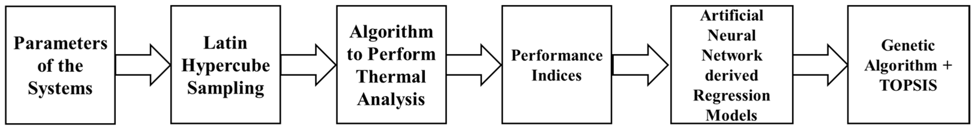
To conduct the thermal evaluation analysis, we used the modeling methods from Moran et al.’s [31] and Ҫengel M. Boles’s works [32]. The major governing equation for the exergetic evaluation of a given control volume for the steady state is given as follows:
0 = j 1 T 0 T j Q ˙ j + W ˙ c v p 0 d V c v d t + i m ˙ i e f i e m ˙ e e f e E ˙ d
The term e f , known as the flow exergy, is given as follows:
e f = h h 0 T 0 s s 0 + V 2 2   + g z
Meanwhile, the heat transfer capacity is given as follows:
U A c o m p o n e n t = Q ˙ c o m p o n e n t L M T D c o m p o n e n t
The appropriate modeling of each of the components can be found in [1,11,12,29].
The exergy destruction of the total system and UA values of the heat exchangers are given as follows:
E d ˙ t o t = E d ˙ O R C , b o i l + E d ˙ O R C , e x p + E d ˙ O R C , c o n d + E d ˙ O R C , p u m p + E d ˙ V C C , e v a p + E d ˙ V C C , c o m p + E d ˙ V C C , c o n d + E d ˙ V C C , t h r o t
Meanwhile, the UA values of the whole system are given as follows:
U A t o t = U A O R C , b o i l + U A O R C , c o n d + U A V C C , e v a p + U A V C C , c o n d

4. Methodology

In order to obtain the values and perform the optimization, a code was developed based on some of the authors’ previous publications, with some modifications. The algorithm was validated with the previously published work. Moreover, in order to attain the optimized values, the complete scheme is given in Figure 2.
Firstly, the range of parameters, deduced from some of the authors’ previous publications provided in Table 2, is used to obtain approximately 1100 values for each of the variables involved. These variables are then shifted to obtain the values of the performance indices mentioned in Equations (4) and (5). These values of the performance indices, which are also 1100 in amount, are then used to obtain the regressed models of them with respect to the input parameters. The Artificial Neural Network (ANN)-derived models for total exergy destruction ( E d t o t ) and the heat exchanger total heat transfer capacity ( U A t o t ) are used. Later on, multi-objective optimization was carried out using the acquired models for Edtot and UAtot using the Genetic Algorithm (GA), followed by the Technique for Order of Preference by Similarity to Ideal Solution (TOPSIS) that was used to single out the optimized value.

5. Results and Discussion

After running the algorithm mentioned in Figure 2, the optimized obtained values are presented in Table 2. The results show the proper fluid choices for a biogas-driven ORC-VCC system by examining total exergy destruction ( E d t o t ) together with total heat capacity ( U A t o t ) as the basis for evaluation. The optimization process of large datasets together with multi-objective parameter optimization requires specialized techniques due to their essential nature. The Genetic Algorithm (GA) serves as a specialized technique for obtaining optimized results when two or more objective functions need optimization. The optimization results showcase the Decane ORC-R600a VCC to be the best candidate for the ORC-VCC system. The optimization solution from TOPSIS recommends the following values for total exergy destruction ( E d t o t ) together with total heat capacity ( U A t o t ): 24.50 kW and 6.71 kW/K, respectively.
The results obtained from the evaluation and optimization are presented in Table 3, which is outlined below.

6. Conclusions

This study demonstrates the potential of integrating ORC-VCC systems powered by biogas as a promising sustainable cooling application. We employed Artificial Neural Network (ANN) models to estimate the key performance indicators of total exergy destruction ( E d t o t ) together with total heat capacity ( U A t o t ). The optimization process selected Decane as the best working fluid together with R600a for an ORC-VCC system, which produced an optimized total exergetic destruction rate of 24.50 kW and total heat transfer capacity of 6.71 kW/K. This research emphasizes how fluid selection impacts system performance while developing a structured method to boost a biogas-driven ORC-VCC system’s operational and thermodynamic efficiency. Future research will center around testing the system in real-time operations while expanding upon the examination of suitable working fluids to incorporate newly developed low-GWP refrigerants to deliver maximum environmental gains.

Author Contributions

Conceptualization, M.T.; methodology, M.T., N.M.M., and M.T.N.; software, M.T., K.F.I., and M.T.N.; validation, M.T., K.F.I., and W.K.; formal analysis, M.T.; investigation, N.M.M.; data curation, M.T., W.K., and M.S.; writing—original draft preparation, M.T.; writing—review and editing, M.T., N.M.M., and M.T.N.; supervision, M.T.N.; project administration, M.T. All authors have read and agreed to the published version of the manuscript.

Funding

This research received no external funding.

Institutional Review Board Statement

Not applicable.

Informed Consent Statement

Not applicable.

Data Availability Statement

The data presented in this study are available upon request from the corresponding author.

Conflicts of Interest

The authors declare no conflicts of interest.

Nomenclature

C P Specific Heat (kJ/kg·K)
E d t o t Exergy Destruction (kW)
h Enthalpy (kJ/kg)
m ˙ Mass Flow Rate (kg/s)
Q ˙ Heat Transfer (kW)
sEntropy (kJ/kg·K)
TTemperature (K)
W ˙ Work (kW)
UAHeat Transfer Capacity (kW/K)
fgFlue Gases
HTFHeat Transfer Fluid
HTF,HXRepresenting heat exchanger handling flue gases and heat transfer fluid

References

  1. Nasir, M.T.; Ekwonu, M.C.; Park, Y.; Esfahani, J.A.; Kim, K.C. Assessment of a district trigeneration biomass powered double organic rankine cycle as primed mover and supported cooling. Energies 2021, 14, 1030. [Google Scholar] [CrossRef]
  2. Kelkar, M. Demise of fossil fuels part I: Supply and demand. Heliyon 2024, 10, e39200. [Google Scholar] [CrossRef]
  3. Inglesi-Lotz, R. The impact of renewable energy consumption to economic growth: A panel data application. Energy Econ. 2016, 53, 58–63. [Google Scholar] [CrossRef]
  4. Strzalka, R.; Schneider, D.; Eicker, U. Current status of bioenergy technologies in Germany. Renew. Sustain. Energy Rev. 2017, 72, 801–820. [Google Scholar] [CrossRef]
  5. Moriarty, P.; Honnery, D. What is the global potential for renewable energy? Renew. Sustain. Energy Rev. 2012, 16, 244–252. [Google Scholar] [CrossRef]
  6. Li, C.; Zhou, J.; Cao, Y.; Zhong, J.; Liu, Y.; Kang, C.; Tan, Y. Interaction between urban microclimate and electric air-conditioning energy consumption during high temperature season. Appl. Energy 2014, 117, 149–156. [Google Scholar] [CrossRef]
  7. Chan, C.W.; Ling-Chin, J.; Roskilly, A.P. A review of chemical heat pumps, thermodynamic cycles and thermal energy storage technologies for low grade heat utilization. Appl. Therm. Eng. 2013, 50, 1257–1273. [Google Scholar] [CrossRef]
  8. Chua, K.J.; Chou, S.K.; Yang, W.M.; Yan, J. Achieving better energy-efficient air conditioning—A review of technologies and strategies. Appl. Energy 2013, 104, 87–104. [Google Scholar] [CrossRef]
  9. Brown, J.S.; Domanski, P.A. Review of alternative cooling technologies. Appl. Therm. Eng. 2014, 64, 252–262. [Google Scholar] [CrossRef]
  10. Zeyghami, M.; Goswami, D.Y.; Stefanakos, E. A review of solar thermo-mechanical refrigeration and cooling methods. Renew. Sustain. Energy Rev. 2015, 51, 1428–1445. [Google Scholar] [CrossRef]
  11. Nasir, M.T.; Ali, M.A.; Khan, T.S.; Al-Hajri, E.; Kadri, M.B.; Kim, K.C. Performance assessment and multi objective optimization of an Organic Rankine Cycle driven cooling air conditioning system. Energy Build. 2019, 191, 13–30. [Google Scholar] [CrossRef]
  12. Nasir, M.T.; Ekwonu, M.C.; Esfahani, J.A.; Kim, K.C. Integrated vapor compression chiller with bottoming organic rankine cycle and onsite low-grade renewable energy. Energies 2021, 14, 6401. [Google Scholar] [CrossRef]
  13. Prigmore, D.; Barber, R. Cooling with the sun’s heat Design considerations and test data for a Rankine Cycle prototype. Sol. Energy 1975, 17, 185–192. [Google Scholar] [CrossRef]
  14. Biancardi, F.R.; Sitler, J.W.; Melikian, G. Development and test of solar Rankine cycle heating and cooling systems. Int. J. Refrig. 1982, 5, 351–360. [Google Scholar] [CrossRef]
  15. Demierre, J.; Henchoz, S.; Favrat, D. Prototype of a thermally driven heat pump based on integrated Organic Rankine Cycles (ORC). Energy 2012, 41, 10–17. [Google Scholar] [CrossRef]
  16. Demierre, J.; Favrat, D.; Schiffmann, J.; Wegele, J. Experimental investigation of a Thermally Driven Heat Pump based on a double Organic Rankine Cycle and an oil-free Compressor-Turbine Unit. Int. J. Refrig. 2014, 44, 91–100. [Google Scholar] [CrossRef]
  17. Wang, H.; Peterson, R.; Harada, K.; Miller, E.; Ingram-Goble, R.; Fisher, L.; Yih, J.; Ward, C. Performance of a combined organic Rankine cycle and vapor compression cycle for heat activated cooling. Energy 2011, 36, 447–458. [Google Scholar] [CrossRef]
  18. Little, A.B.; Garimella, S. Comparative assessment of alternative cycles for waste heat recovery and upgrade. Energy 2011, 36, 4492–4504. [Google Scholar] [CrossRef]
  19. Cola, F.; Romagnoli, A.; Hey Heng Kiat, J. An evaluation of the technologies for heat recovery to meet onsite cooling demands. Energy Convers. Manag. 2016, 121, 174–185. [Google Scholar] [CrossRef]
  20. Bao, J.; Zhao, L. A review of working fluid and expander selections for organic Rankine cycle. Renew. Sustain. Energy Rev. 2013, 24, 325–342. [Google Scholar] [CrossRef]
  21. Aziz, F.; Mudasar, R.; Kim, M.H. Exergetic and heat load optimization of high temperature organic Rankine cycle. Energy Convers. Manag. 2018, 171, 48–58. [Google Scholar] [CrossRef]
  22. Inc, B. Waste Heat Recovery: Technology Opportunities in the US Industry. 2008; pp. 1–112. Available online: http://www1.eere.energy.gov/manufacturing/intensiveprocesses/pdfs/waste_heat_recovery.pdf (accessed on 10 March 2025).
  23. Lai, N.A.; Wendland, M.; Fischer, J. Working fluids for high-temperature organic Rankine cycles. Energy 2011, 36, 199–211. [Google Scholar] [CrossRef]
  24. Shu, G.; Li, X.; Tian, H.; Liang, X.; Wei, H.; Wang, X. Alkanes as working fluids for high-temperature exhaust heat recovery of diesel engine using organic Rankine cycle. Appl. Energy 2014, 119, 204–217. [Google Scholar] [CrossRef]
  25. Li, H.; Bu, X.; Wang, L.; Long, Z.; Lian, Y. Hydrocarbon working fluids for a Rankine cycle powered vapor compression refrigeration system using low-grade thermal energy. Energy Build. 2013, 65, 167–172. [Google Scholar] [CrossRef]
  26. Saleh, B. Parametric and working fluid analysis of a combined organic Rankine-vapor compression refrigeration system activated by low-grade thermal energy. J. Adv. Res. 2016, 7, 651–660. [Google Scholar] [CrossRef]
  27. Bu, X.; Wang, L.; Li, H. Performance analysis and working fluid selection for geothermal energy-powered organic Rankine-vapor compression air conditioning. Geotherm. Energy 2013, 1, 1–14. [Google Scholar] [CrossRef]
  28. Toffolo, A.; Lazzaretto, A.; Manente, G.; Paci, M. A multi-criteria approach for the optimal selection of working fluid and design parameters in Organic Rankine Cycle systems. Appl. Energy 2014, 121, 219–232. [Google Scholar] [CrossRef]
  29. Nasir, M.T.; Kim, K.C. Working fluids selection and parametric optimization of an Organic Rankine Cycle coupled Vapor Compression Cycle (ORC-VCC) for air conditioning using low grade heat. Energy Build. 2016, 129, 378–395. [Google Scholar] [CrossRef]
  30. Meng, N.; Li, T.; Wang, J.; Jia, Y.; Liu, Q.; Qin, H. Synergetic cascade-evaporation mechanism of a novel building distributed energy supply system with cogeneration and temperature and humidity independent control characteristics. Energy Convers. Manag. 2020, 209, 112620. [Google Scholar] [CrossRef]
  31. Moran, M.; Shapiro, H.; Boettner, D.; Bailey, M. Fundamentals of Engineering Thermodynamics, 9th ed.; Wiley & Sons Ltd.: Hoboken, NJ, USA, 2018. [Google Scholar]
  32. Çengel, Y.; Boles, M.A. Thermodynamics: An Engineering Approach, 5th ed.; McGraw-Hill: New York, NY, USA, 2006. [Google Scholar]
Figure 1. The schematic of the system considered for providing air conditioning.
Materproc 23 00001 g001
Figure 2. The complete scheme of obtaining optimized values.
Materproc 23 00001 g002
Table 1. List of working fluid compositions.
Working FluidCritical Pressure (kPa)Critical Temperature (°C)ODPGWP
M-Xylene3534.5343.730Very low
Decane2103344.550Very low
Propylcyclohexane2860357.650Very low
Butane (R600)3790152020
Isobutane (R600a)3640135020
Table 2. Selected parametric ranges.
ParameterRange
ORC Evaporator Temperature325 °C–335 °C
ORC Condenser Temperature50 °C–70 °C
ORC Condenser Sub-Cooling Temperature0 °C–14 °C
Isentropic Efficiency Expander0.7–0.9
Isentropic Efficiency Pump0.75–0.9
Pinch Point Temperature Evaporator ORC5 °C–15 °C
VCC Evaporator Temperature−2 °C–5 °C
VCC Condenser Temperature50 °C–70 °C
Isentropic Efficiency Compressor0.7–0.9
Pinch Point Temperature HTF HX5 °C–15 °C
Pinch Point Temperature Condenser ORC5 °C–15 °C
Pinch Point Temperature Condenser VCC3 °C–14 °C
Table 3. Optimized values of system exergy destruction and UA values.
Working Fluid Combination E d t o t U A t o t
Decane ORC-R600 VCC42.1916.07
Decane ORC-R600a VCC24.506.71
M-Xylene ORC-R600 VCC21.0413.96
M-Xylene ORC-R600a VCC30.0616.49
C3CC6 ORC-R600 VCC14.5519.87
C3CC6 ORC-R600a VCC12.8415.26
Disclaimer/Publisher’s Note: The statements, opinions and data contained in all publications are solely those of the individual author(s) and contributor(s) and not of MDPI and/or the editor(s). MDPI and/or the editor(s) disclaim responsibility for any injury to people or property resulting from any ideas, methods, instructions or products referred to in the content.

