Proceeding Paper

Predicting the Flexural Modulus of Variable Pitch Angle, Porous Bouligand Structured 3D Printed Polymer †

School of Engineering, The University of Edinburgh, Sanderson Building, Robert Stevenson Road, The King’s Buildings, Edinburgh EH9 3FB, UK
*
Author to whom correspondence should be addressed.
Presented at the 1st International Online Conference on Biomimetics (IOCB 2024), 15–17 May 2024; Available online: https://sciforum.net/event/IOCB2024.
Mater. Proc. 2025, 20(1), 1; https://doi.org/10.3390/materproc2025020001
Published: 8 January 2025
(This article belongs to the Proceedings of The 1st International Online Conference on Biomimetics)

Abstract

:
Our study considered porous Bouligand structured polymer, comprising polymer fibres with porous spaces between them. These are more complicated structures than the non-porous Bouligand, since the addition of porosity into the material creates a secondary variable besides fibre pitch. There is currently no analytical model available to predict the modulus of such materials. Our paper explores the correlation between porosity, polymer fibre pitch angle, and flexural modulus in porous Bouligand structured polymers. Our structures were digitally manufactured using stereolithography (SLA) additive manufacturing methods, after which they were subjected to three-point bending tests. Our aim was to simply and parametrically develop an analytical model that would capture the influences of both porosity and polymer fibre pitch angle on the flexural modulus of the material. Our model is expressed as E f = E p o r o ( a θ f 3 + b θ f 2 + c θ f + d ) , and we derive this by applying non-linear regression to our experimental data. This model predicts the flexural modulus, E f , of porous Bouligand structured polymer as a function of both porosity and pitch angle. Here, E p o r o is defined as the solid material modulus, E s o l i d , multiplied by porosity, ϕ and is a linear reduction in the modulus as a function of increasing porosity, while θ f signifies the polymer fibre pitch angle. This relationship is relatively accurate within the range of 10° ≤ θf ≤ 50°, and for porosity values ranging from 0.277 0.356 , as supported by our evidence to date.

1. Introduction

The terms biomimetics and bioinspiration [1,2] are frequently employed to describe novel approaches to engineering and design in the fields of chemistry, material science, and engineering. Biomimicry is more commonly being seen as a solution to several contemporary technical challenges, as insights and ideas derived from similar solutions to problems can often be found in the natural world. In addition, there is already plenty of evidence that show engineering insights as gained from the study of Nature, successfully addressing technological problems in materials science [3], architecture [4], aerodynamics, and mechanical engineering [5].
The twisted plywood or Bouligand structure is a commonly observed microstructural pattern in biological materials. It is known for having exceptional impact strength and multi-directional toughness. Examples of organisms exhibiting a twisted plywood configuration include the osteons of bone and the dactyl club of the mantis shrimp [6], and the exoskeletons of crustaceans such as crabs and lobsters [7].
According to a study by Alam et al. [8], the ductile plunger of the snapping shrimp (Alpheus shrimp) has a sandwich composite microstructure, consisting of mineral-rich outer and inner layers, a chitin-rich middle layer with a porosity of approximately 50%, and a Bouligand orientation as shown in Figure 1a–d. Furthermore, the structure of the plunger in the snapping shrimp is presumed to protect the delicate internal tissues from damage caused by high pressures, built up within the plunger-socket system during ‘snapping’ events. Figure 1e shows a schematic illustration of porous Bouligand, inspired by the snapping shrimp’s ductile plunger. It is a biologically inspired design displaying the helicoidal geometry with its well-designed porosity mimicking the damage-tolerant and thermal resistance found by Alam.
Taoye Lu et al. [7] evaluated bending of helicoidal carbon fibre-reinforced polymer composites (CFRPC) laminated plates to discover the optimal layup. They found in numerical calculations that a combination-form helicoidal layup pattern could decrease dimensionless bending deflection of laminated plates by more than 5%, compared to quasi-isotropic plates, with very good out-of-plane bending performance. Similarly, Zhe Feng Yu et al. [10] analysed the mechanical properties of helicoidal laminates with regular and non-linear pitch angles with additional 0° plies. They measured the basic pitch angles at 10° and 20° by using low-velocity impact and compression-after-impact (CAI) testing, and then added 0° plies. With 0° orientation plies, the CAI strength was significantly improved while the impact resistance was excellent.
The Bouligand architecture is sometimes viewed as a difficult architecture to mimic, as there is manufacturing complexity that arises from the required sequential helical rotations of fibres from layer to layer [11]. Conventional manufacturing methods are not able to swiftly replicate complex Bouligand structures, and as such, progress in this area has been slow until recent years where there has been a surge in research using additive manufacturing technologies. Since additive manufacturing (3D printing) is now commonplace in many engineering labs, the fabrication of complex structures has become much easier [12]. Recently for example, the impact resistance of nacre-like composites were additively manufactured with a range of diverse patterns [13,14].
Lizhi Guan et al. [15] studied Bouligand structured materials, inspired after the impact damage tolerant mantis shrimp’s dactyl club. They tested for flexure on 3D-printed composites bolstered with glass microfibres in a Bouligand configuration. It found that composites at 40° pitch had the highest mechanical properties, with a flexural strength of 36.9 MPa, stiffness of 2.26 GPa, and energy absorbance of 8 kJ/m2.
Three-dimensional printed helicoidal structures have been shown to improve the mechanical properties of printed polymers over other print orientations. Sun et al. [16] for example, found that 3D-printed helicoidal PLA specimens exhibited a 12.1% and 101% improvement in tensile strength and toughness, respectively, over conventional cross-printed (0/90) configurations. An elaboration on the work of Sun et al., nevertheless, would be to include porosity into the structure. Lightweighting is an important concept in engineering design. There is currently no study of the impact that porosity has on the mechanical performance of Bouligand structured 3D printed polymers. Yet, there are natural porous structures that make use of porosity as a means of controlling deformation, improving thermomechanical resistance, and lightweighting. This paper aims to begin filling this gap in design knowledge by considering prediction models for porous Bouligand structured polymers.

2. Materials and Methods

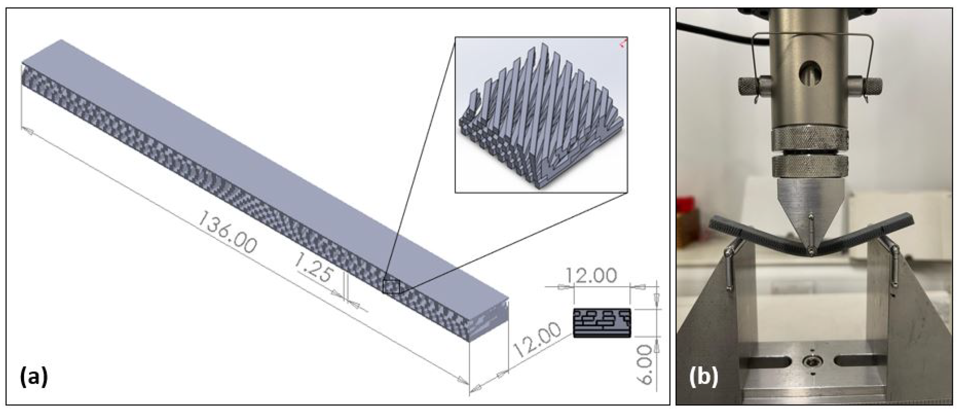
Porous Bouligand-structured polymers with varying porosity and pitch angles were designed using SolidWorks and fibres were designed to have a square-cross section. In this study, “fibre spacing” refers to the distance between printed fibres, and each layer is referred to as a “ply”, for simplicity. The angle between plies is referred to as the “pitch angle”. The design parameters for these materials are presented in Table 1. Porosity was controlled by treating the printed fibre spacing distance as an independent variable, and pitch angles were also varied independently, from one printed ply to the next. 5-layer, 6 mm thick porous Bouligand structured polymers were manufactured using a Form 3 SLA 3D printer and Tough 2000 resin by Formlabs Inc. (Somerville, MA, USA) (resin properties detailed in Table 2). Five plies, each 1 mm thick, were printed, resulting in a total thickness of 5 mm, and 0.5 mm thick plates at the upper and lower surfaces increased this to 6 mm. Samples were cured in accordance with the manufacturer instructions for Tough 2000 resin. Figure 2a shows a CAD of the porous Bouligand structured polymer printed for three-point bending tests, with a fibre spacing 1.25 mm. The figure has precise measurements and an image of the internal anatomy, which can be more clearly understood to comprehend the layout and structure of the test specimen.

2.1. Three-Point Bending

The flexural properties were determined by three-point bending in accordance with ASTM D790 [17]. The sample lengths were 22× times the thickness, while the widths were 2× the sample thickness. The width of each specimen was fixed at 12 mm, and the span-to-depth ratio in the three-point bend test rig was fixed at 16:1. The test speed was determined based on the thickness and span length of each sample, as prescribed by ASTM D790. Testing was conducted in an Instron 3369 by Instron (Norwood, MA, USA) at a crosshead rate of 10 mm/min. A three-point bending test set-up is shown in Figure 2b.

2.2. Models to Predict the Elastic Modulus

Due to a highly variable internal structure, our designed structures differ significantly from conventional cellular solids. As such, the common modulus predicting models used for engineering composites cannot satisfactorily be applied to porous Bouligand structured polymers. Models proposed for two-phase particulate ceramics were seen, therefore, as a useful starting point in understanding the effect of porosity on elastic properties [9]. Equation (1) is a linear fit model, and simply assumes that the elastic modulus of porous materials ( E p o r o ) is inversely proportional to the fraction of porosity ( ϕ ) [18], and this reduction is applied to the elastic modulus of the polymer bulk, E p .
E p o r o = E p ( 1 ϕ )
Equation (2) is a power model, and is similar to the linear fit model, except that the porosity is modified by the fitting parameters a and b.
E p o r o = E p ( 1 a ϕ b )
This is often expressed by including a numerical exponent, as demonstrated in studies by Brown et al., Phani et al., Maitra and Phani, and Wagh et al. [19,20,21].
The equation is modified here as follows (Equation (3)):
E p o r o = E p ( 1 a ϕ 2 3 )
A predictive model by Alam [9], shown in Equation (4), has demonstrated high accuracy for particle-polymer composites including porosity. Alam’s model modifies the rule of mixtures to account for the effective binder fraction in contact with the particulates, a stress transfer aspect ratio, and a reinforcement aspect ratio. Here, s t is the stress transfer aspect ratio [22], l r d r is the reinforcement aspect ratio, A is an anfractuosity parameter, w ( p , m a x ) is the maximum pore width measured against material width w, and V r and V m are the volume fractions of reinforcement and matrix, respectively.
E p o r o = ( E r V r l r d r × 1 s t + E m V m , e f f ) × 1 A × 1 w p , m a x w
Since our 3D printed structures do not include any reinforcement, we modify Alam’s model to account for this (Equation (5)).
E p o r o = E p V p × 1 A × 1 w p , m a x w

3. Results and Discussion

3.1. Flexural Properties

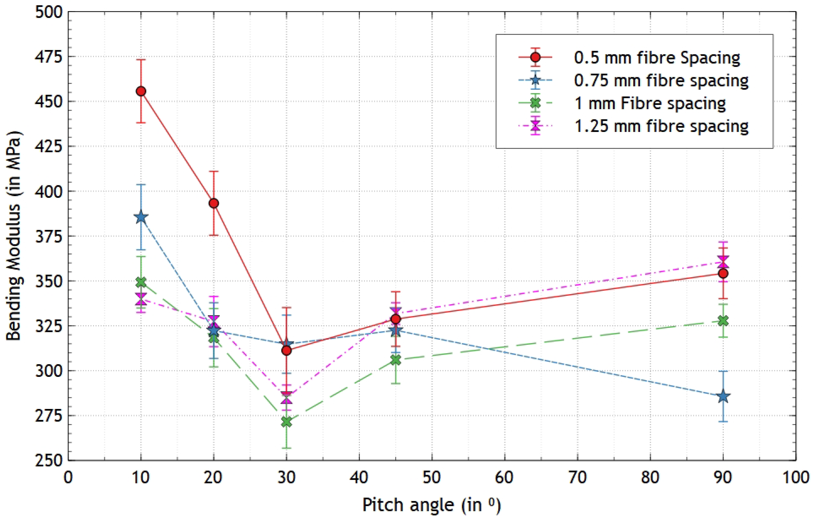
Figure 3 shows the flexural modulus of the different porous Bouligand structured polymer coupons and samples sets, given variable porosity and ply angle. Generally, as the fibre spacing of the materials increase from 0.5 mm to 1.25 mm, the flexural modulus decreases. This is because porosity increases with fibre spacing and there is less material resisting loading in the more porous materials. The flexural modulus is also noted to decrease as the pitch angle increases from 10° to 30°, reaching a minimum at 30°. The overall flexural modulus then continues to increase above a pitch angle 30°. The maximum flexural modulus is observed for samples with a 0.5 mm fibre spacing and a 10° pitch angle, while the lowest flexural modulus is observed in samples with a 1.25 mm fibre spacing and a 30° pitch angle. Lower pitch angles (10–30°) ensure that the fibres of the Bouligand model are more closely aligned with the direction of load in the three-point bending test to improve load transfer and deformation resistance, leading to a higher flexural modulus. Yet, at a 30° pitch angle, a combination of decreased fibre alignment, structural anisotropy, and poor load-bearing due to fibre misalignment all contribute to a dramatic reduction in modulus.

3.2. Elastic Modulus Prediction

The elastic modulus of each porous Bouligand structured polymer ( E p o r o ) was calculated using a linear fit, power fit, and the modified Alam model. Polynomial regression was applied to the data from the models predict the elastic modulus ( E p r e d i c t e d ) for the porous Bouligand structured polymer. Table 3 compares the ratios of E e x p e r i m e n t a l to E p r e d i c t e d for the different models used. The predictive equations (linear fit, power fit, and modified Alam model) simplify the relationship between porosity and modulus but fail to include local reinforcement based on real-world porosity distributions or microstructural influences such as fibre interactions and stress redistribution. Variations such as curing and test alignment, or sample preparation might also contribute to a higher stiffness measured in experiments. These combination of microstructural complexity and experimental environment explains the prevailing trend of E e x p e r i m e n t a l to E p r e d i c t e d > 1.0, as is clear in Table 3. Fitting the flexural testing data to a third-degree polynomial produced the corresponding Pearson’s coefficient (R2) as 0.9768, 0.9893, 0.9892, and 0.9232. These figures correspond to porous Bouligand-based polymers with fibre diameters of between 0.5 and 1.25 mm. Polynomial regression was further applied to the models to develop a predictive for the elastic properties of the porous Bouligand structured polymers.
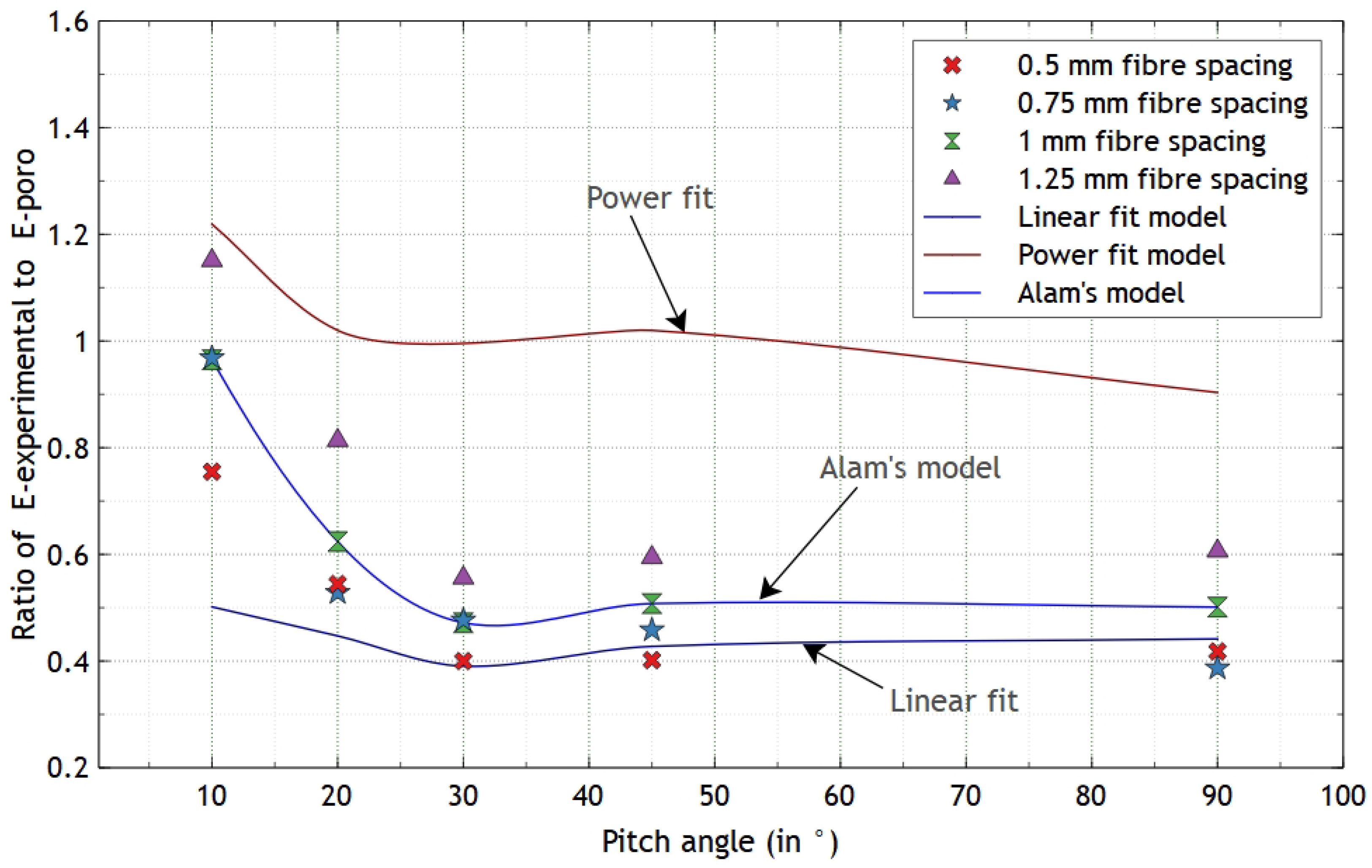
The ratio of E e x p e r i m e n t a l to E p o r o was plotted against the pitch angles, as shown in Figure 4. This graph describes the relationship between the experimental elastic modulus and the predicted modulus. The graph indicates a decrease in the ratio as the pitch angle increases from 10° to 30°, followed by a plateau after the 45° pitch angle. Additionally, regression based predictions are applied based on the linear fit, the power fit and the modified Alam fit discussed earlier. Additionally, in Figure 4, it is clear that the power fit significantly over-predicts, while the linear fit predicts values at the minimum extent of each sample set. The modified Alam model makes predictions that lie closer to the mean and median values for each sample set, and it is therefore clear that the modified Alam model yield superior predictions as compared against the linear and power models. The elastic modulus prediction equation E f = E p o r o ( a θ f 3 + b θ f 2 + c θ f + d ) was obtained by using third-order polynomial regression on Alam’s model. This model is highly accurate in the smaller range of pitch angles between 10° to 45°. The equation is accurate at lower fibre spacings (0.5 mm to 0.75 mm), giving porosities of 0.277 to 0.356. With pitch angles over 50°, the model indicates that the elastic modulus ratio stabilizes, suggesting a constant relationship irrespective of further increase in pitch angle.

4. Conclusions

This study considers models capable of predicting flexural modulus of porous Bouligand structured polymer. Three-point bending tests are conducted, and there is a particular emphasis on varying the fibre spacing and pitch angle, and the effects these have on the flexural properties. The results indicate that the flexural modulus of the 3D-printed samples decreases as the pitch angle increases from 10° to 30°, reaching its minimum at 30°, and then increases at pitch angles of 45° and 90°. Increasing the fibre spacing from 0.5 mm to 1.25 mm results in a decrease in the bending modulus, with the highest modulus observed at 0.5 mm and the lowest at 1.25 mm. This is, in part, due to that an increase in the fibre spacing results in a concurrent increase in porosity. Among the models evaluated for predicting the elastic modulus of the porous Bouligand structured polymers, the modified Alam model proved to be the most accurate. By applying polynomial regression to this model, the following predictive equation was derived: E f = E p o r o ( a θ f 3 + b θ f 2 + c θ f + d ) , This relationship is relatively accurate within the pitch angle range of 10° ≤ θf ≤ 50° and for porosity values ranging from 0.277 0.356 .

Author Contributions

Conceptualization, P.A.; methodology, P.S.P., E.D.M. and P.A.; validation, P.S.P., E.D.M. and P.A.; formal analysis, P.S.P. and P.A.; investigation, P.S.P.; resources, P.A.; data curation, P.S.P.; writing—original draft preparation, P.S.P.; writing—review and editing, E.D.M. and P.A.; visualization, P.S.P.; supervision, E.D.M. and P.A.; project administration, P.A.; funding acquisition, P.S.P. All authors have read and agreed to the published version of the manuscript.

Funding

This research was funded by The Directorate of Technical Education, Maharashtra State, India.

Institutional Review Board Statement

Not applicable.

Informed Consent Statement

Not applicable.

Data Availability Statement

Data will be made available from the corresponding author on reasonable request.

Conflicts of Interest

The authors declare no conflicts of interest.

References

  1. Sanchez, C.; Arribart, H.; Guille, M.M. Biomimetism and bioinspiration as tools for the design of innovative materials and systems. Nat. Mater. 2005, 4, 277–288. [Google Scholar] [CrossRef] [PubMed]
  2. Fratzl, P. Biomimetic materials research: What can we really learn from nature’s structural materials? J. R. Soc. Interface 2007, 4, 637–642. [Google Scholar] [CrossRef]
  3. Jeronimidis, G. Wood, one of nature’s challenging composites. Symp. Soc. Exp. Biol. 1980, 34, 169–182. [Google Scholar] [PubMed]
  4. Kemp, M. Structural intuitions and metamorphic thinking in art, architecture and science. In Proceedings of the Metamorph—9th International Architecture Exhibition, Venice, Italy, 12 September–7 November 2004; pp. 30–43. [Google Scholar]
  5. Milwich, M.; Speck, T.; Speck, O.; Stegmaier, T.; Planck, H. Biomimetics and technical textiles: Solving engineering problems with the help of nature’s wisdom. Am. J. Bot. 2006, 93, 1455–1465. [Google Scholar] [CrossRef] [PubMed]
  6. Natarajan, B.; Gilman, J.W. Bioinspired Bouligand cellulose nanocrystal composites: A review of mechanical properties. Philos. Trans. R. Soc. Math. Phys. Eng. Sci. 2018, 376, 20170050. [Google Scholar] [CrossRef] [PubMed]
  7. Lu, T.; Shen, H.S.; Chen, H.W.X.; Feng, M. Optimization Design and Nonlinear Bending of Bio-Inspired Helicoidal Composite Laminated Plates. Materials 2023, 16, 4550. [Google Scholar] [CrossRef]
  8. Alam, P.; Sanka, I.; Alam, L.P.; Wijaya, S.; Sintya, E.; Handayani, N.S.N.; ller, A. The snapping shrimp dactyl plunger: A thermomechanical damage-tolerant sandwich composite. Zoology 2018, 126, 1–10. [Google Scholar] [CrossRef]
  9. Alam, P. Porous Particle-Polymer Composites. In Advances in Composite Materials; Tesinova, P., Ed.; IntechOpen: Rijeka, Croatia, 2011; Chapter 2. [Google Scholar] [CrossRef]
  10. Yu, Z.; Du, X.; Liu, R.; Xie, Q.; Zhang, X.; Zhu, Q. Increasing the Compressive Strength of Helicoidal Laminates after Low-Velocity Impact upon Mixing with 0 Orientation Plies and Its Analysis. Matrerials 2023, 16, 4599. [Google Scholar] [CrossRef] [PubMed]
  11. Yang, Y.; Chen, Z.; Song, X.; Zhang, Z.; Zhang, J.; Shung, K.K.; Zhou, Q.; Chen, Y. Biomimetic Anisotropic Reinforcement Architectures by Electrically Assisted Nanocomposite 3D Printing. Adv. Mater. 2017, 29, 1–8. [Google Scholar] [CrossRef] [PubMed]
  12. Danfeng, W.; Chen, D.D.; Chen, Z. Recent Progress in 3D Printing of Bioinspired Structures. Front. Mater. 2020, 7, 1–10. [Google Scholar] [CrossRef]
  13. Ko, K.; Jin, S.; Lee, S.E.; Hong, J.W. Impact resistance of nacre-like composites diversely patterned by 3D printing. Compos. Struct. 2020, 238, 111951. [Google Scholar] [CrossRef]
  14. Ko, K.; Jin, S.; Lee, S.E.; Lee, I.; Hong, J.W. Bio-inspired bimaterial composites patterned using three-dimensional printing. Compos. Part B Eng. 2019, 165, 594–603. [Google Scholar] [CrossRef]
  15. Guan, L.; Peng, W.; Wen, R.N.; Fan, J.; Le Ferrand, H. Izod impact resistance of 3D printed discontinuous fibrous composites with Bouligand structure. Npg Asia Matrerials 2023, 15, 60. [Google Scholar] [CrossRef]
  16. Sun, Y.; Tian, W.; Zhang, T.; Chen, P.; Li, M. Strength and toughness enhancement in 3d printing via bioinspired tool path. Mater. Des. 2020, 185, 108239. [Google Scholar] [CrossRef]
  17. ASTM D790-17; Standard Test Method for Flexural Properties of Unidirectional and Reinforced Plastics and Electric Insulating Materials. ASTM: West Conshohochen, PA, USA, 2017.
  18. Alam, P. Composites Engineering: An A–Z Guide; IOP Publishing: Bristol, UK, 2021; pp. 2053–2563. [Google Scholar] [CrossRef]
  19. Brown, S.D.; Biddulph, R.B.; Wilcox, P.D. A Strength–Porosity Relation Involving Different Pore Geometry and Orientation. J. Am. Ceram. Soc. 1964, 47, 320–322. [Google Scholar] [CrossRef]
  20. Maitra, A.K.; Phani, K.K. Ultrasonic evaluation of elastic parameters of sintered powder compacts. J. Mater. Sci. 1994, 29, 4415–4419. [Google Scholar] [CrossRef]
  21. Wagh, A.; Singh, J.; Poeppel, R. Dependence of ceramic fracture properties on porosity. J. Mater. Sci. 1993, 28, 3589–3593. [Google Scholar] [CrossRef]
  22. Hull, D.; Clyne, T. An Introduction to Composite Materials; Cambridge University Press: Cambridge, UK, 1996. [Google Scholar]
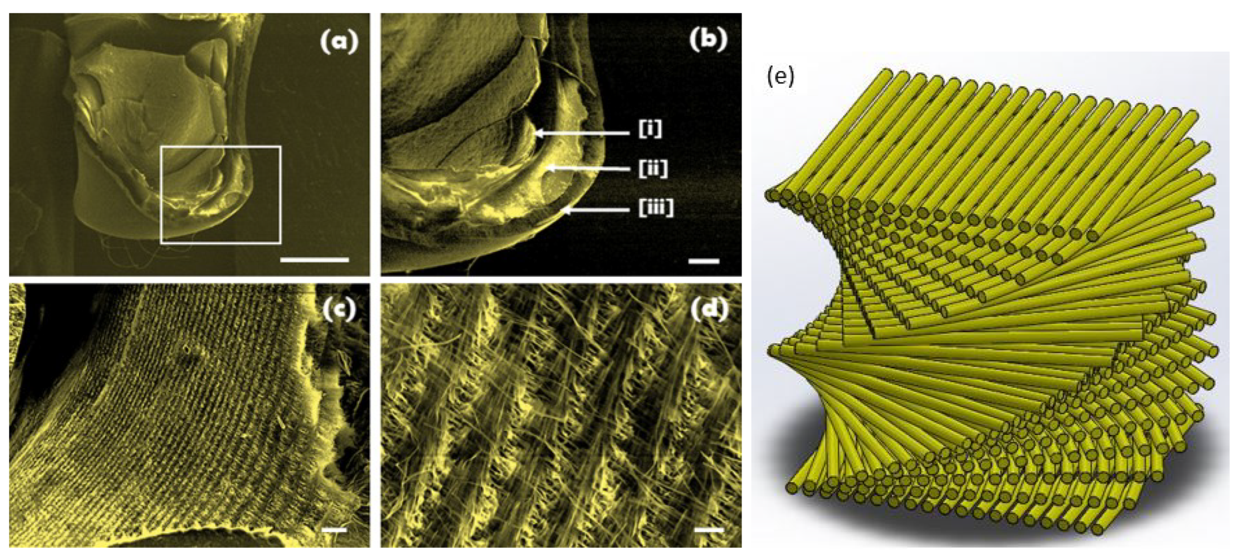
Figure 1. SEM micrographs of (a) the cross-section of a fractured plunger (scale bar = 1 mm), (b) the bottom of the fractured plunger of snapping shrimp identifying the inner [i], middle [ii] and outer [iii] layers (scale bar = 200 μm), (c) a closer view of the middle layer showing it to be a laminated porous structure comprising pine-treeshaped matter (scale bar = 20 μm), and (d) a higher magnification of the porous pine-tree structures (scale bar = 3 μm), reproduced from [9] with the permission of Elsevier, and (e) schematic representation of the porous helicoidal architecture.
Materproc 20 00001 g001
Figure 2. (a) CAD model for designed 3-point bending porous Bouligand structured specimen; (b) Instron 3369 3-point bending test set-up (96 mm span).
Materproc 20 00001 g002
Figure 3. Average bending modulus against pitch angle for porous Bouligand structured polymer coupons with variable fibre spacing.
Materproc 20 00001 g003
Figure 4. Ratio of E e x p e r i m e n t a l and E p o r o against pitch angle for porous Bouligand structured polymer coupons with variable fibre spacing (applying the modified Alam model (Equation (5)) to determine the elastic modulus).
Materproc 20 00001 g004
Table 1. Specimen configurations.
DescriptionPrinting DirectionFibre Spacing (in mm)
Helicoidal, 10° ply angle0°, 10°, 20°, 30°, 40°0.5, 0.75, 1, 1.25
Helicoidal, 20° ply angle0°, 20°, 40°, 60°, 80°0.5, 0.75, 1, 1.25
Helicoidal, 30° ply angle0°, 30°, 60°, 90°, 120°0.5, 0.75, 1, 1.25
Quasi-isotropic0°, 45°, 90°, 135°, 180°0.5, 0.75, 1, 1.25
Cross-ply0°, 90°, 180°, 270°, 360°0.5, 0.75, 1, 1.25
Table 2. Properties of Tough 2000 resin (Formlabs Inc. (Somerville, MA, USA)).
PropertiesValueRemark
Young’s Modulus1.2 GPaASTM 638-14
Ultimate Tensile strength46 MPaASTM 638-14
Density1.11 g/mm3
Poisson’s Ratio0.3
Table 3. Comparing the ratio of E e x p e r i m e n t a l to E p r e d i c t e d for porous Bouligand structured polymer materials with variable fibre spacing showing the elastic modulus predictions based on linear fit, power fit, and the modified Alam model.
Fibre Spacing (mm)Linear FitPower FitModified Alam Fit
0.50.79400.41721.1055
0.750.87430.75030.9567
11.07041.15180.923
1.251.15871.13821.1693
Disclaimer/Publisher’s Note: The statements, opinions and data contained in all publications are solely those of the individual author(s) and contributor(s) and not of MDPI and/or the editor(s). MDPI and/or the editor(s) disclaim responsibility for any injury to people or property resulting from any ideas, methods, instructions or products referred to in the content.