Abstract
In the field of the development of modern techniques, which improve and/or regenerate the component’s surface properties, High Velocity Oxygen Fuel (HVOF) spraying of carbides or metals and their alloys is a good alternative method to other conventional surface engineering ones, including magnesium foundry alloys. Coatings manufactured by thermal spraying are used to improve the durability and life time of machine parts, both the new and regenerated ones, by changing the surface layer properties. In this work the results of HVOF sprayed coatings deposited onto AZ31 magnesium alloy substrate are reported. The feeding material was composite powder Cr3C2–NiCr. The coatings were investigated in terms of their microstructure and selected mechanical properties. For structure examinations, microscopy studies (light and scanning ones) were used as well as phase composition analysis. In the case of mechanical properties, the wear resistance was determined also microhardness was measured.
1. Introduction
The development of technology forces the demand for functional and technological surfaces that are increasingly more perfect. Knowledge of techniques for the production of surface layers and coatings allows their proper selection for specific operating conditions. One of the many methods of extending the life of machine parts, both new and regenerated, and as a result of increasing their reliability and operational durability is the application of coatings by means of thermal spraying technology, which consists of producing metal, carbide, ceramic and composite coatings on a properly prepared substrate with almost any chemical and phase composition. Spraying is mainly used to make coatings with high resistance to abrasion, protection against high temperature and corrosion [1,2,3,4].
One of the most commonly used methods is supersonic thermal spraying of HVOF (High Velocity Oxygen Fuel), which allows the production of coatings with special properties, among others: low oxidation, very low porosity and high adhesion [5,6]. These coatings are free of oxides, which is often required due to their operational properties, and is difficult to obtain by other thermal spraying methods. The main materials used in thermal spraying HVOF are chromium carbide or tungsten carbide particles in a metal alloy matrix consisting of various combinations of Cr, Ni or Co. The one of the most common coatings is Cr3C2/NiCr because chromium carbide coating with a ductile nickel binder is very often used in industrial environments to protect against abrasive wear and corrosion. So, the main goal ofcoating with cermet is to increase wear resistance of parts and resistance to oxidation. It could also work as an alternative to hard chrome plating [7,8,9,10,11].
For several years, there has been a visible interest in non-ferrous alloys, including magnesium alloys, which are the subject of research in many research and development centers, as well as in major manufacturers of the machine-building, chemical, energy, textile, electronic, office, aeronautical, and in particular the automotive, shipbuilding, aviation and sports industries. The growing trends in the production of magnesium alloys indicate an increased need for their use in the global construction industry, and, thus, these alloys will become one of the most commonly used construction materials of our century, so it is extremely important to maintain a high pace of research on the problems of light alloys [12,13].
2. Materials and Methods
2.1. Coatings deposition
Investigations were carried out on samples from the AZ31 magnesium alloy substrate (Institute of Non-Ferrous Metals in Gliwice, Skawina, Poland), with a 5 mm thickness. The chemical composition of the alloy is shown in Table 1.

Table 1.
The chemical composition of the AZ31 magnesium alloy [14,15].
The feedstock material for the coatings manufacturing was Cr3C2—25 wt.% NiCr. The powder particles size distribution was in the range of −30 to + 5 μm. It was a commercially available powder (Amperit 588.059-Höganäs). The morphology of the initial powder is presented in Figure 1.
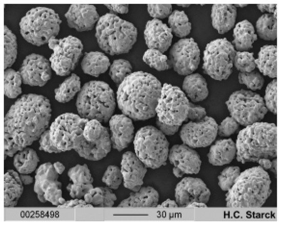
Figure 1.
SEM (secondary electrons) micrographs of the Cr3C2–NiCr powder [16].
The chemical composition of the feedstock powder, which was used in coatings manufacturing process is given in Table 2.

Table 2.
The chemical composition of the chromium carbide powder Cr3C2–NiCr [16].
Before spraying all samples were sand blasted with corundum to get a surface roughness in the range of Ra equal to 17 μm. Then the substrates were coated by the coating material using a C-CJS spray system by Thermico. The thermal spraying was made by CERTECH Company, Wilamowice, Poland. Kerosene and oxygen were used as the fuel gases with flow rates of 40 l/min and 350 l/min, respectively, whereas nitrogen was used as the carrier gas with a flow rate of 10 l/min. The powder feed rate was fixed at 25 g/min. The spray distance was equal to 280 mm.
2.2. Coatings Characterization
Samples for metallographic observations were prepared by standard grinding and polishing techniques. Microstructure observations were made using a scanning electron microscope, SEM (Supra 35, Zeiss, Oberkochen, Germany) using secondary electron and backscattered detectors. The chemical composition was analyzed by EDS. Light microscopy (Axio Obsever, Zeiss, Oberkochen, Germany) was used to determine the coating thickness measured at random places. The average from 10 measurements was statistically calculated. In order to determine the phase composition of the Cr3C2–NiCr coating, X-ray diffraction, XRD, tests were carried out. XRD investigations of sprayed coatings were done by X-ray diffractometer X’Pert Pro MPD by Panalytical (Almelo, The Netherlands) apparatus with a copper anode lamp (λKα = 0.154 nm) (Panalytical, Almelo, The Netherlands) as well as a PIXcel 3D detector (Panalytical, Almelo, the Netherlands) on the diffracted beam axis. The diffraction lines were recorded in Bragg–Brentano geometry in the angular scope of 15–90°, with the step of 0.03° and the step time of 0.8 s. The analysis of the obtained diffraction patterns was made in Panalytical High Score Plus software (Version 3.0e), containing a dedicated flat-file base of PAN - ICSD phase identification. The testing of mechanical properties was started by measurement of coating adhesion. Microhardness distribution of coated specimen from the surface to substrate was estimated using the Vickers hardness test method with a force equal to 2.94 N (HV0.3). The tests were performed along lines perpendicular to the specimen surfaces, along the run face axis. The wear resistance of the manufactured coating was analyzed using the “pin-on-disc” tribological test. As a counter body, a 6 mm diameter ball of zirconium oxide, ZrO2 was used. During the test, the friction coefficient was recorded. The test was performed at room temperature using the testing conditions given in Table 3. The wear track dimensions after tests were measured by a Sutronic 25-Taylor Hobson profilometer (Taylor Hobson Ltd., Leicester, England), and the topography was analyzed using an SEM to determine the mechanism of the wear.

Table 3.
Testing conditions of the “pin-on-disc” method.
3. Results
3.1. Coatings Microstructure
The cross section micrographs show that obtained coatings are characterized by a homogeneous and dense structure. It was revealed that coating was well bonded to the substrate, there was no discontinuity at the interface. The porosity was low and the average pore size was also small. It could be observed, that the Cr3C2 particles were surrounded by the Ni–Cr matrix, which well adhered to the carbide particles. Figure 2 shows the cross-section of the manufactured coating.

Figure 2.
Cross-section of manufactured coating: (a) mag. 150×, (b) mag. 500× and (c), mag. 2500×.
The phase composition of manufactured coating is given in Figure 3. As could be seen, there were two phases, namely Cr3C2 and CrNi3. There were also some indications of C. For qualitative and quantitative analysis the RIR (Reference Intensity Ratio) method [17] was used. There was about 65% of the Cr3C2 phase and around 35% of the CrNi3 phase. Similar phase composition could be found e.g., in [18,19].
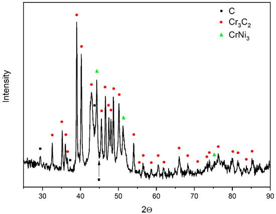
Figure 3.
XRD pattern of the manufactured coating.
3.2. Microhardness
Based on the results of the investigations, it was found that the microhardness of the coating increases, and the maximum value is obtained as 790 HV0.3, while the minimum hardness is about 180 HV0.3, which means that the produced coating has increased in hardness compared to the substrate (AZ31) by about 338% (Figure 4.). An increase in temperature during the HVOF spraying process causes oxidation and the formation of a protective layer on the surface of the coating which does not affect its hardness. On the basis of XRD (Figure 3) analysis it was found that the existence of a Cr3C2 phase provides an increase in hardness of the Cr3C2–NiCr coating. It was reported in [20] that due to very high speed, powder particles can melt and dissolve carbides to varying degrees. Moreover, the particles are not exactly the same size, so small particles melt completely and larger particles do not melt completely. The wide size range of powder particles causes some particles to overheat significantly while others are insufficiently melted, which may be the cause of increased porosity and reduced coating hardness. Furthermore, an increase in the size of the carbide causes an increase in the porosity of the coating [20].
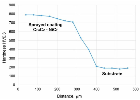
Figure 4.
Hardness distribution of coated sample from the surface to substrate.
3.3. Wear Resistance
The results of dry sliding wear test show, that the manufactured coating exhibits good resistance for wear. The volumetric wear of investigated coatings was equal to 13.88 ± 3.11 × 10⁻⁶ mm3/(N-m). The friction coefficient was equal to 0.6 ± 0.03. Similar values could be found in the literature [21,22] The typical wear trace is given in Figure 5.
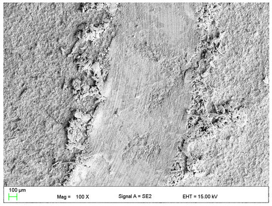
Figure 5.
Wear tracks of Cr3C2–NiCr coatings, mag. 100×.
During microscopic observation of wear tracks, it was found that the dominant mechanism of wear is a classic adhesive one. On the worn surface such phenomena as decohesion areas, oxidation wear (because of increasing temperature during tests), plastic and fatigue wear and areas of smearing of the debris from counter-body (ZrO2 ball) could be observed. Similar wear mechanism could be found e.g., in [23]. Some of these phenomena are presented in Figure 6.
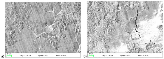
Figure 6.
Different wear mechanism of Cr3C2–NiCr coating: (a) low cycle fatigue, and (b) spallation and cracks.
4. Conclusions
In this preliminary study, the Cr3C2–NiCr coatings were manufactured by the HVOF method on the magnesium alloy AZ31. Based on the carried out investigations, the following conclusions can be drawn:
- The obtained coating is characterized by a homogeneous and dense structure, also no cracks or discontinuities were found on the surface of the produced Cr3C2–NiCr coating.
- The thickness of the manufactured coating was about 300 ± 15 µm.
- Measurements of the microhardness distribution in the sprayed coating indicate an increase up to 790 HV 0.3 (substrate material was equal to 180 HV 0.3).
- In the sprayed coatings are two main phases, namely Cr3C2 and CrNi3.
- The dominant mechanism of wear is a classic adhesive one.
Author Contributions
E.J. conceived and designed the experiments; G.W. performed the thermal spraying coating; L.Ł. analyzed the data; E.J. and L.Ł. wrote the paper—review and editing. All authors have read and agreed to the published version of the manuscript.
Funding
These investigations were financed by the Ministry of Science and Higher Education of Poland, Grant DEC—2019/03/X/ST5/00830. The authors are thankful to Nuckowski, P. and Pakieła, W. (Silesian University of Technology, Gliwice, Poland) for help with investigations.
Conflicts of Interest
The authors declare no conflict of interest.
References
- Davis, J.R. (Ed.) Handbook of Thermal Spray Technology; ASM International: Materials Park, OH, USA, 2004. [Google Scholar]
- Fauchais, P.L.; Heberlein, J.V.R.; Boulos, M.I. Thermal Spray Fundamentals: From Powder to Part; Springer: New York, NY, USA, 2014. [Google Scholar]
- Pawłowski, L. The Science and Engineering of Thermal Spray Coatings, 2nd ed.; Wiley: Chichester, UK, 2008. [Google Scholar]
- Gan, J.A.; Berndt, C.C. Nanocomposite coatings: Thermal spray processing, microstructure and performance. Int. Mater. Rev. 2015, 60, 195–244. [Google Scholar] [CrossRef]
- Houdkova’, S.; Kasparova’, M.; Zahalka, F. The influence of spraying angle on properties of HVOF sprayed hardmetal coatings. J. Therm. Spray Technol. 2010, 19, 893–901. [Google Scholar] [CrossRef]
- Poirier, D.; Legoux, J.G.; Lima, R.S. Engineering HVOF-sprayed Cr3C2-NiCr coatings: The effect of particle morphology and spraying parameters on the microstructure, properties, and high temperature wear performance. J. Therm. Spray Technol. 2013, 22, 280–289. [Google Scholar] [CrossRef]
- Guilemany, J.M.; Espallargas, N.; Suegama, P.H.; Benedetti, A.V. Comparative study of Cr3C2–NiCr coatings obtained by HVOF and hard chromium coatings. Corros. Sci. 2006, 48, 2998–3013. [Google Scholar] [CrossRef]
- Lin, L.; Li, G.; Wang, H.; Kang, J.-J.; Xu, Z.-L.; Wang, H.-J. Structure and wear behavior of NiCr–Cr3C2 coatings sprayed by supersonic plasma spraying and high velocity oxy-fuel technologies. Appl. Surf. Sci. 2015, 356, 383–390. [Google Scholar] [CrossRef]
- Karaoglanli, A.C.; Oge, M.; Doleker, K.M.; Hotamis, M. Comparison of tribological properties of HVOF sprayed coatings with different composition. Surf. Coat. Technol. 2017, 318, 299–308. [Google Scholar] [CrossRef]
- Sahraoui, T.; Fenineche, N.E.; Montavon, G.; Coddet, C. Structure and wear behavior of HVOF sprayed Cr3C2–NiCr and WC–Co coatings. Mater. Des. 2003, 24, 309–313. [Google Scholar] [CrossRef]
- Bobzin, K.; Zhao, L.; Öte, M.; Königstein, T.; Steeger, M. Impact wear of an HVOF-sprayed Cr3C2–NiCr coating. Int. J. Refract. Met. Hard Mater. 2018, 70, 191–196. [Google Scholar] [CrossRef]
- Mordike, B.L.; Ebert, T. Magnesium: Properties–applications–potential. Mater. Sci. Eng. A 2001, 302, 37–45. [Google Scholar] [CrossRef]
- Dobrzański, L.A.; Tański, T.; Dobrzańska-Danikiewicz, A.D.; Król, M.; Malara, S.; Domagała-Dubiel, J. Structure and properties of Mg-Al-Zn alloys. Open Access Libr. 2012, 5/11, 11–25. [Google Scholar]
- Yang, Z.; Li, J.P.; Zhang, J.X.; Larimer, G.W.; Robson, J. Review and research and development of magnesium alloys. Acta Metall. Sin. 2008, 5, 313–328. [Google Scholar] [CrossRef]
- Zagórski, I.; Pieśko, P. Comparative investigation on surface roughness of selected magnesium alloys after milling with a full-carbide tool and PKD Prog. Sci. Technol. 2011, 8, 53–58. [Google Scholar]
- Available online: www.hoganas.com/en (accessed on 20 April 2020).
- Prevey, P.S. X-ray diffraction characterization of crystallinity and phase composition in plasma-sprayed hydroxyapatite coatings. J. Therm. Spray Technol. 2000, 9, 369–376. [Google Scholar] [CrossRef]
- Murthy, J.K.N.; Venkataraman, B. Abrasive wear behavior of WC–CoCr and Cr3C2–20(NiCr) deposited by HVOF and detonation spray processes. Surf. Coat. Technol. 2006, 200, 2642–2652. [Google Scholar] [CrossRef]
- Matthews, S.; James, B.; Hyland, M. The role of microstructure in the mechanism of high velocity erosion of Cr3C2–NiCr thermal spray coatings: Part 1—As-Sprayed coatings. Surf. Coat. Technol. 2009, 203, 1086–1093. [Google Scholar] [CrossRef]
- Hajare, A.S.; Gogteb, C.L. Comparative study of wear behavior of Thermal Spray HVOF coating on 304 SS. Mater. Today: Proc. 2018, 5, 6924–6933. [Google Scholar]
- Sidhu, H.S.; Sidhu, B.S.; Prakash, S. Wear characteristics of Cr3C2–NiCr and–Co coatings deposited by LPG fueled HVOF. Tribol. Int. 2010, 43, 887–890. [Google Scholar] [CrossRef]
- Gariboldi, E.; Rovatti, L.; Lecis, N.; Mondora, L.; Mondora, G.A. Tribological and mechanical behavior of Cr3C2–NiCr thermally sprayed coatings after prolonged aging. Surf. Coat. Technol. 2016, 305, 83–92. [Google Scholar] [CrossRef]
- Bolelli, G.; Berger, L.M.; Borner, T.; Koivuluoto, H.; Matikainen, V.; Lusvarghi, L.; Lyphout, D.; Markocsan, N.; Nylen, P.; Sassetelli, P.; et al. Sliding and abrasive wear behavior of HVOF- and HVAF-sprayed Cr3C2–NiCr hard metal coatings. Wear 2016, 358–359, 32–50. [Google Scholar] [CrossRef]
Publisher’s Note: MDPI stays neutral with regard to jurisdictional claims in published maps and institutional affiliations. |
© 2020 by the authors. Licensee MDPI, Basel, Switzerland. This article is an open access article distributed under the terms and conditions of the Creative Commons Attribution (CC BY) license (https://creativecommons.org/licenses/by/4.0/).