Proceeding Paper

Laser-Induced Graphene as Electrode Material in Proton-Exchange Membrane Fuel Cells †

1
Department of Applied Science and Technology (DISAT), Politecnico di Torino, 10129 Turin, Italy
2
Center for Sustainable Future Technologies@PoliTo, Istituto Italiano di Tecnologia, 10144 Turin, Italy
*
Authors to whom correspondence should be addressed.
Presented at the 4th International Online Conference on Nanomaterials, 5–19 May 2023; Available online: https://iocn2023.sciforum.net/.
Mater. Proc. 2023, 14(1), 33; https://doi.org/10.3390/IOCN2023-14520
Published: 5 May 2023
(This article belongs to the Proceedings of The 4th International Online Conference on Nanomaterials)

Abstract

:
The preparation of graphene foams via laser pyrolysis of polyimides has gained success due to its ease and speed of processing. Established applications of laser-induced graphene (LIG) involve micro-supercapacitors, batteries, sensors, and water treatment. However, to the best of our knowledge, only a few studies have focused on potential applications of LIG in proton-exchange membrane fuel cells (PEM-FCs). In this study, we demonstrate that LIG obtained from SPEEK films (LIG-S) presents all the key features required of a PEM-FC electrode. Moreover, electrochemical tests in rotating disk and half-cell setups highlight the intrinsic catalytic activity of LIG towards the oxygen reduction reaction. This activity is attributed to structural defects in the LIG lattice and sulfur doping incorporated from the SPEEK precursor, and it may lower the catalyst loading required to reach competitive cell performance.

1. Introduction

Increasing environmental concerns and climate change are forcing a global energy transition towards a more sustainable future. In this context, green hydrogen appears to be a promising new energy vector due to its high energy density, and proton-exchange membrane fuel cells (PEM-FCs) are one of the means by which hydrogen fuel can be directly converted into electricity [1,2,3].
The Membrane-Electrode Assembly (MEA) is the heart of a PEM-FC. Traditionally, a MEA is composed of two porous carbon-based gas diffusion electrodes (GDEs), decorated with a platinum catalyst, and hot-pressed on each side of a Nafion™ membrane [4].
However, to reach wider commercial availability and convenience, PEM-FCs are still undergoing development to reduce production and maintenance costs and enhance reliability and performance. Both cost and performance are associated with the MEA and the materials it is composed of [5].
In this study, we provide evidence that laser-induced graphene (LIG-S) obtained via laser pyrolysis of sulfonated poly (ether ether ketone) (SPEEK) membranes is an inexpensive and easily fabricated material that has all the key features required of a GDE in PEM-FCs. Electrochemical tests highlight the intrinsic catalytic activity of the obtained LIG-S towards the oxygen reduction reaction (ORR) occurring at the cathode in PEM-FCs. Moreover, SPEEK membranes have already been widely employed as an environmentally friendly alternative PEM to Nafion™ [6]. Therefore, this study paves the way for an all-SPEEK PEM-FC.

2. Materials and Methods

2.1. SPEEK Films Synthesis

The SPEEK films were obtained from a solution of SPEEK with water and ethanol, following an analogous procedure to [7]. The resulting SPEEK films ranged between 5 cm and 10 cm in diameter and were only a few micrometers thin.

2.2. LIG-S Fabrication

The LIG-S material was fabricated using a commercial laser scriber by Microla Optoelectronics S.r.l., equipped with a pulsed CO2 source. The maximum nominal power of the CO2 laser source is 30 W. The system operates in ambient conditions, and it offers the possibility to tune the raster scan, power percentage, frequency, and scan velocity of the laser beam. The beam is controlled by a galvanometric scanner, and the spot diameter is 270 µm on the sample. The maximum working area is 70 × 70 mm2.
The SPEEK film was simply placed upon a commercial carbon paper (CP) substrate (Sigracet 28 BC) and constrained with tape to keep it in place during laser scribing. The obtained LIG-S adhered to CP and was used as is.

2.3. Physico-Chemical and Morphological Characterizations

Raman characterizations were performed with a Renishaw inVia Reflex micro-Raman spectrophotometer equipped with a cooled CCD camera. The excitation was provided by an Ar–Kr laser source operating at a wavelength of 514.5 nm. The laser spot was ~20 µm in diameter.
Morphology and EDX data were obtained with a Zeiss Supra 40 Field Emission Scanning Electron Microscope (FESEM).

2.4. Electrochemical Characterizations

All electrochemical characterizations were acquired with a CH1760E electrochemical workstation (CH Instruments, Inc., Bee Cave, TX, USA). RRDE measurements were performed with a RRDE-3A Rotating Ring Disk Electrode Apparatus (ALS Co., Ltd., Tokyo, Japan). Gas Diffusion Electrode (GDE) tests were performed with a Gaskatel FlexCell-PTFE electrochemical test cell.
RRDE experiments were conducted in a 0.1 M perchloric acid (HClO4 70%, Sigma-Aldrich, St. Louis, Missouri, USA) electrolyte in a four-electrode configuration. The LIG-S onto CP sample was deposited onto the disk-shaped Glassy Carbon working electrode using a Nafion™ 117-containing solution as binder (~5% in a mixture of lower aliphatic alcohols and water, Sigma-Aldrich). A graphite rod was used as a counter electrode. The reference electrode was an Ag–AgCl electrode (197 mV versus the reference hydrogen electrode) (BioLogic RE-1B reference electrode, in 3 M NaCl). The fourth electrode was connected to the platinum ring to measure the residual amount of reduced HO2 in the electrolyte and compare the disk and ring currents. In this setup, the electrolyte has been saturated with gases (either nitrogen or oxygen) for at least 20 min prior to the measurements.
GDE tests were performed with a 2 M perchloric acid (HClO4 70%, Sigma-Aldrich) electrolyte in a three-electrode configuration. The working electrode was obtained by attaching copper tape to the back of the LIG-S on a CP sample. This was conducted to improve the electrical contact between the CP and the gold-plated banana plugs exiting out of the Gaskatel FlexCell. The counter electrode and reference electrode were the same as in the RRDE experiments. Prior to the GDE experiments, most of the LIG-S sample had been passivated with insulating tape on the side in contact with the electrolyte to achieve an exposed active area of approximately 9 × 9 mm2.

3. Results

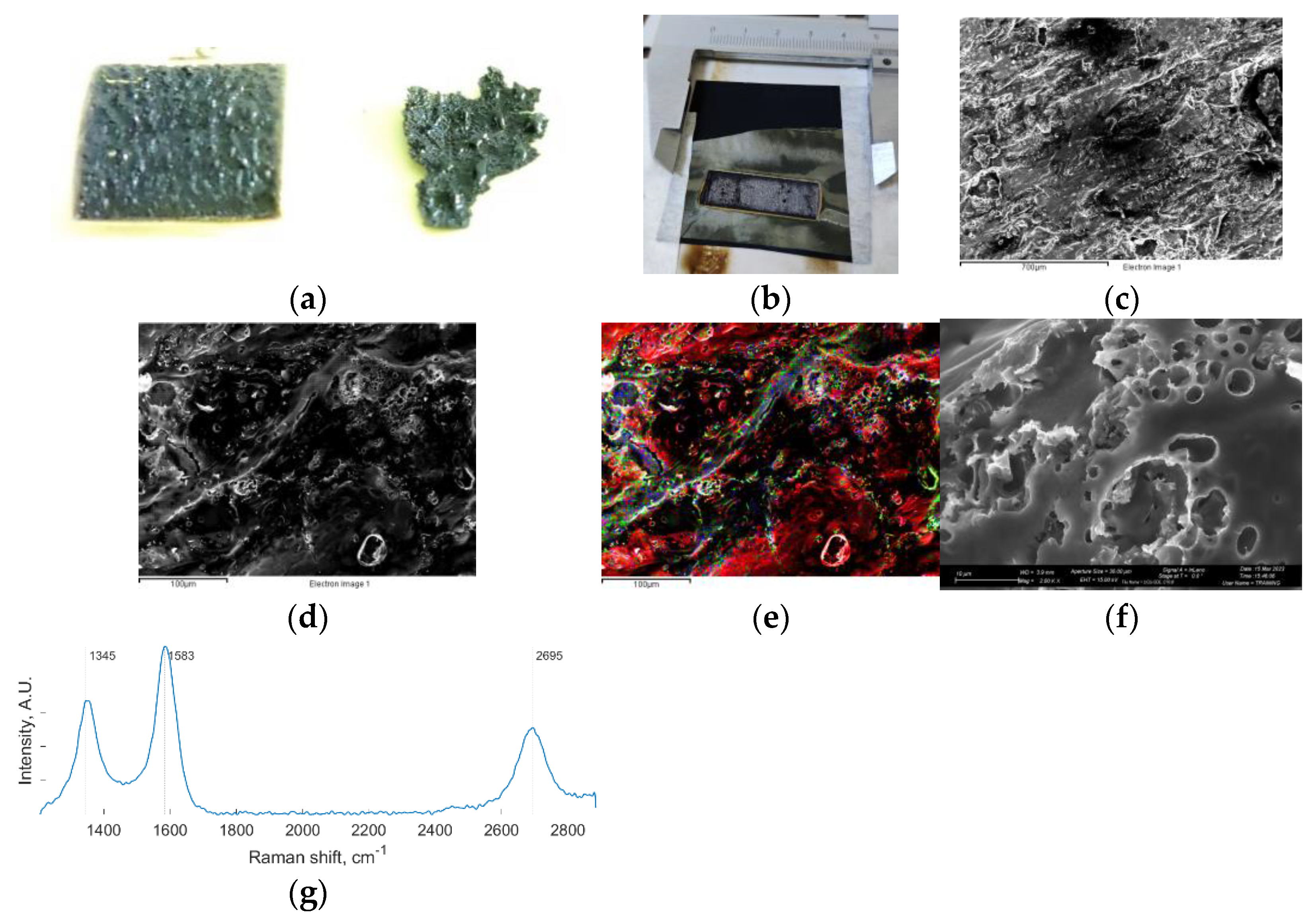
3.1. Laser Graphitization of SPEEK

The photothermal process initiated by the laser scriber on SPEEK allowed the nearly complete conversion of thin SPEEK films into LIG-S [7,8]. Some SPEEK remained on the back side of the film, which was reached by a lower heat flux. This SPEEK was melted instead of being converted into LIG and quickly solidified into the droplets visible in Figure 1a.
Only thin SPEEK films could be completely converted into LIG-S due to the extremely localized high temperature induced by the laser. The LIG-S obtained was also very thin and, therefore, fragile. For this reason, the procedure was revised, and the SPEEK film was placed on a commercial carbon paper (CP) substrate before laser scribing. The remaining melted polymer on the back side of the SPEEK film allowed the LIG-S to bond with the CP. Thus, the CP substrate simply provided the LIG-S with mechanical support, and by being porous on its own, it still allowed the LIG-S to be evaluated in GDE setups. The obtained LIG-S onto CP is shown in Figure 1b.
The morphology of the obtained LIG-S is presented in Figure 1c,d,f at different magnifications. The LIG-S surface has a foam-like appearance, with an intricate porosity network extending at different scales. The energy dispersive X-ray (EDX) map in Figure 1e shows that the LIG-S sample is mostly composed of carbon (red), with some remaining oxygen (green) and sulfur (blue) impurities. This is confirmed by the LIG-S Raman spectrum in Figure 1g, which was slightly processed to better highlight its features. Specifically, a linear interpolation was subtracted to the recorded spectrum from remove the fluorescence background, and two noise-reducing filters were applied (a 1D median filter and a Savitzky–Golay filter).
The Raman spectrum displayed the three typical peaks of graphitic carbon [9]. The D peak at ~1350 cm−1 is activated by single-phonon intervalley scattering mediated by defective sites in the graphitic lattice. The G peak at 1580 cm−1 is the fingerprint of sp2 carbon lattices. Finally, the second-order 2D peak at ~2700 cm−1 is extremely sensitive to the stacking order of graphitic layers and is originated by scattering events involving two zone-boundary phonons. The ratio between the integrated intensities of the D and G peaks is an indicator of the crystallinity of the sample. In this case, ID/IG ≈ 0.7 signals highly crystallized material. The empirical expression by Tuinstra and Koenig reveals the approximate crystallite size. This expression depends on the D and G peak intensities, and it returned a crystallite size of La ≈ 24 nm [10]. The 2D peak appeared to be wide and of low intensity, but it could be fitted by a single Lorentzian curve. These features are indicative of a few-layer graphene with randomly stacked layers, a structure also known as turbostratic.

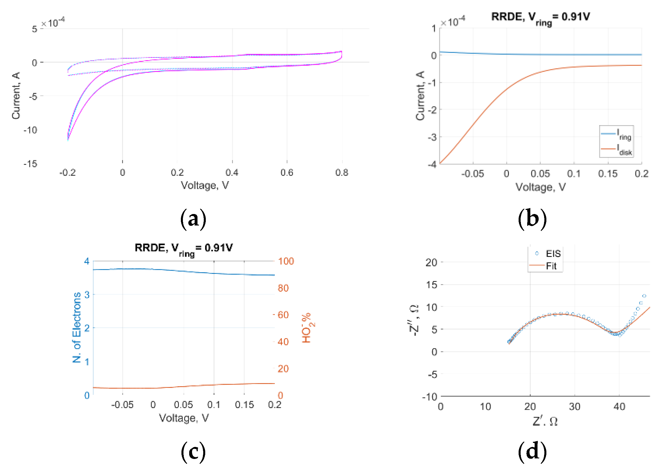
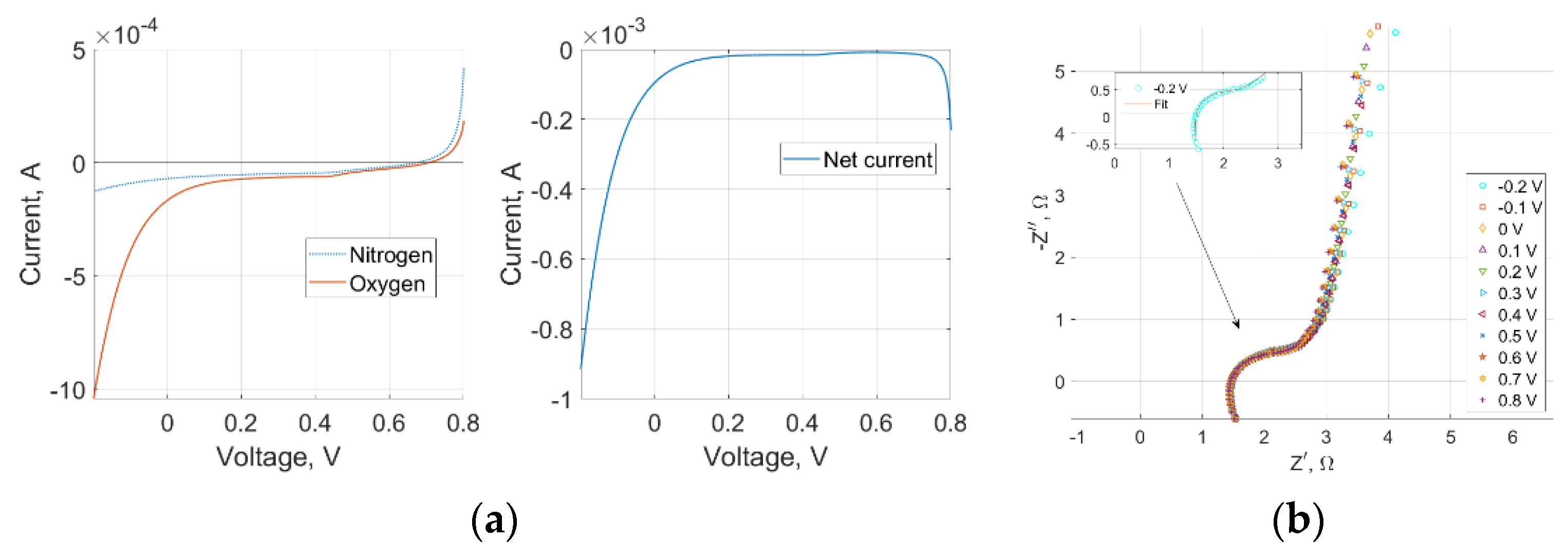
3.2. Electrochemical Performance of LIG-S

All experiments performed in this work were aimed at determining the intrinsic catalytic activity of the LIG-S towards the ORR without the contribution of any specific catalyst that could improve its performance. Preliminary cyclic voltammetry (CV) and linear sweep voltammetry (LSV) were performed with an inert nitrogen gas in both the RRDE and GDE experiments. This is carried out to quantify the background current in capacitive samples such as the LIG-S. Different CV scan rates were employed as an activation procedure for the alleged catalytic sites before the measurements with oxygen gas [11].
An intrinsic ORR activity of the LIG-S sample emerged from both CV and LSV in both setups, as significantly higher negative (cathodic) currents were detected with oxygen gas than with nitrogen gas, as displayed in Figure 2a and Figure 3a. The RRDE data also contained additional information. High disk currents and low ring currents across the range of relevant operating voltages indicated that the preferred reaction site was indeed the LIG-S, as shown in Figure 2b. An impressive stability was observed in the average number of electrons involved in the ORR that is represented in Figure 2c. The number of electrons peaked at 3.75 and never decreased below 3.5. These values are remarkably close to the ideal four-electron number obtained with platinum catalysts. Further confirmation came from the amount of oxygen undergoing two consecutive two-electron reactions, which is quantified by the amount of HO2 further reduced to water by the platinum ring. As represented in Figure 2c, the amount of HO2 always remained below 10% across the entire voltage range, solidifying the previous findings.
Electrochemical Impedance Spectroscopy (EIS) was performed in both RRDE and GDE setups at −0.2 V, corresponding to the ORR current peak of LIG-S. In both cases, the frequency spanned the 1 Hz to 100 kHz range, and the superimposed signal had an amplitude of 10 mV. The Nyquist plot derived in the RRDE experiment, which is displayed in Figure 2d, depicted a clear charge transfer with a characteristic time constant equal to 0.4 ms. The impedance semicircle was diffusion-limited only towards the lower end of the frequency range. Instead, the Nyquist plot derived in the GDE experiment highlighted a more sluggish charge transfer across the entire voltage range, in which the diffusion-limited portion took over at higher frequencies than in the RRDE setup. As a result, the charge transfer semicircle was overall less defined, as it is possible to see in Figure 3b. A high-frequency inductive component appeared only in the GDE Nyquist plot and was attributed to the electrical wiring connecting the GDE setup to the electrochemical workstation.

4. Discussion

The laser scribing process successfully managed to convert the polymeric SPEEK into a graphene-like material. The transition was clearly noticeable by the color change that occurred to the material: the transition from yellow to black and metallic grey is clearly noticeable in Figure 1b. FESEM and EDX images revealed a micro- and nano-structured material composed of a highly defective porous carbon matrix with embedded sulfur and oxygen impurities. Raman investigations provided the definitive proof that a graphene-like material had been obtained. Moreover, the LIG-S presented all the key features required of a PEM-FC electrode: electrical conductivity, porosity to allow fuel gases to reach the reaction sites, and high surface area due to its micro- and nano-features to improve the likelihood of having reactive sites.
The ORR occurring in PEM-FCs can be assessed with different electrochemical setups. Among these, the RRDE setup is generally the most common, as it allows researchers to determine the intrinsic ORR activity of a catalyst. The four-electrode RRDE setup can quantify the amount of oxygen that is reduced to water via the direct four-electron reaction, which is the faster and preferred path, as well as the amount of oxygen that undergoes two successive two-electron reactions [12].
It is extremely rare to achieve a one-to-one correspondence between the high performance of a catalyst as observed in RRDE setups and the performance of the complete cell. This is due to the ideal scenario that an RRDE setup simulates: oxygen gas is dissolved into the electrolyte and is brought towards the catalyst-coated working electrode by forced convection originated by the rotating electrode.
Recently, GDE setups have been established as an intermediate step between RRDE and full cell setups. They have also been defined as half-cell setups, in which the electrolyte is still liquid but the full GDE is being tested. The oxygen gas reaches the reaction sites by diffusion through the porous electrode, and a true three-phase boundary is formed at the GDE–electrolyte interface (H+ ions in the liquid electrolyte, gaseous oxygen fuel, and solid-state catalyst) [11,12,13,14].
This explains the slightly sluggish charge transfer observed in the GDE tests. Nonetheless, the ORR activity observed in the RRDE setup translated relatively well into the GDE half-cell setup, proving that the LIG-S can function as a PEM-FC gas diffusion electrode.

5. Conclusions

The laser scribing process is an easy, quick, and inexpensive solution to convert SPEEK films into LIG porous foams. The obtained LIG-S can effortlessly adhere to a CP substrate by means of melted traces of remaining SPEEK, and it can be tested as is in common RRDE setups as well as in more recent GDE half-cell setups. An intrinsic activity towards the ORR emerges from these experiments, confirming that the sample can indeed function as a GDE in PEM-FCs, with the added advantage of its ease of fabrication. These results may lead to an all-SPEEK PEM-FC employing a SPEEK proton-exchange membrane and LIG-S electrodes. SPEEK membranes would be more environmentally friendly than Nafion™ membranes, and LIG-S electrodes would require lower catalyst loadings to reach competitive cell performance due to their intrinsic ORR activity.

Author Contributions

Conceptualization, methodology, validation, formal analysis, and manuscript writing and editing, T.S., G.M., P.Z., M.F., C.F.P., G.C., S.B. and M.Q.; investigation and data curation were mainly performed by T.S.; supervision, project administration, and funding acquisition, M.Q., S.B., G.C. and C.F.P. All authors have read and agreed to the published version of the manuscript.

Funding

Tommaso Serra’s Ph.D. grant was funded by the National Operational Program (PON) Research and Innovation 2014–2020 (CCI 2014IT16M2OP005), resources FSE REACT-EU, Action IV.5 “Dottorati su tematiche Green”.

Institutional Review Board Statement

Not applicable.

Informed Consent Statement

Not applicable.

Data Availability Statement

Data sharing not applicable.

Acknowledgments

The authors acknowledge the contributions of G. Ferraro and S. Bocchini for the synthesis of the SPEEK films, and J. Zeng for the conversations regarding electrochemical characterizations.

Conflicts of Interest

The authors declare no conflict of interest.

References

  1. European Commission. A Hydrogen Strategy for a Climate-Neutral Europe. 2020. Available online: https://ec.europa.eu/commission/presscorner/api/files/attachment/865942/EU_Hydrogen_Strategy.pdf.pdf (accessed on 4 May 2023).
  2. Publications Office of the EU. Hydrogen Roadmap Europe. 2019. Available online: https://op.europa.eu/en/publication-detail/-/publication/0817d60d-332f-11e9-8d04-01aa75ed71a1/language-en (accessed on 4 May 2023).
  3. Niakolas, D.K.; Daletou, M.; Neophytides, S.G.; Vayenas, C.G. Fuel Cells are a commercially viable alternative for the production of “clean” energy. Ambio 2016, 45, 32–37. [Google Scholar] [CrossRef] [PubMed]
  4. Bhosale, A.C.; Ghosh, P.C.; Assaud, L. Preparation methods of membrane electrode assemblies for proton exchange membrane fuel cells and unitized regenerative fuel cells: A review. Renew. Sustain. Energy Rev. 2020, 133, 110286. [Google Scholar] [CrossRef]
  5. Dai, W.; Wang, H.; Yuan, X.Z.; Martin, J.J.; Yang, D.; Qiao, J.; Ma, J. A review on water balance in the membrane electrode assembly of proton exchange membrane fuel cells. Int. J. Hydrogen Energy 2009, 34, 9461–9478. [Google Scholar] [CrossRef]
  6. Kim, S.Y.; Kim, S.; Park, M.J. Enhanced proton transport in nanostructured polymer electrolyte/ionic liquid membranes under water–free conditions. Nat. Commun. 2010, 1, 88. [Google Scholar] [CrossRef] [PubMed]
  7. Lamberti, A.; Serrapede, M.; Ferraro, G.; Fontana, M.; Perrucci, F.; Bianco, S.; Chiolerio, A.; Bocchini, S. All-SPEEK flexible supercapacitor exploiting laser-induced graphenization. 2D Mater. 2017, 4, 035012. [Google Scholar] [CrossRef]
  8. Lin, J.; Peng, Z.; Liu, Y.; Ruiz-Zapeda, F.; Ye, R.; Samuel, E.L.G.; Yacaman, M.J.; Yakobson, B.I.; Tour, J.M. Laser-Induced porous graphene films from commercial polymers. Nat. Commun. 2014, 5, 5714. [Google Scholar] [CrossRef] [PubMed]
  9. Malard, L.M.; Pimenta, M.A.; Dresselhaus, G.; Dresselhaus, M.S. Raman spectroscopy in graphene. Phys. Rep. 2009, 473, 51–87. [Google Scholar] [CrossRef]
  10. Tuinstra, F.; Koenig, J.L. Raman spectrum of graphite. J. Chem. Phys. 1970, 53, 1126–1130. [Google Scholar] [CrossRef]
  11. Gridin, V.; Du, J.; Haller, S.; Theis, P.; Hofmann, K.; Wiberg, G.K.H.; Kramm, U.I.; Arenz, M. GDE vs. RDE: Impact of operation conditions on intrinsic catalytic parameters of FeNC catalyst for the oxygen reduction reaction. Electrochim. Acta 2023, 444, 142012. [Google Scholar] [CrossRef]
  12. Vracar, L.J. Oxygen Reduction Reaction in Acid Solution. In Enciclopedia of Applied Electrochemistry; Kreysa, G., Ota, K., Savinell, R.F., Eds.; Springer: New York, NY, USA, 2014. [Google Scholar] [CrossRef]
  13. Nösberger, S.; Du, J.; Quinson, J.; Berner, E.; Zana, A.; Wiberg, G.K.H.; Arenz, M. The gas diffusion electrode setup as a testing platform for evaluating fuel cell catalysts: A comparative RDE-GDE study. Electrochem. Sci. Adv. 2022, 3, e2100190. [Google Scholar] [CrossRef]
  14. Ehelebe, K.; Schmitt, N.; Sievers, G.; Jensen, A.W.; Hrnjić, A.; Jiménez, P.C.; Kaiser, P.; Geuß, M.; Ku, Y.P.; Jovanovič, P.; et al. Benchmarking Fuel Cell Electrocatalysts Using Gas Diffusion Electrodes: Inter–lab Comparison and Best Practices. ACS Energy Lett. 2022, 7, 816–826. [Google Scholar] [CrossRef]
Figure 1. (a) Back side of the LIG-S with remaining SPEEK droplets; (b) LIG-S onto CP at the end of the laser scribing process; (c) Low magnification FESEM of the LIG-S surface; (d) Intermediate magnification FESEM of the LIG-S surface; (e) EDX map of (d) showing carbon (red), oxygen (green), and sulfur (blue); (f) High magnification FESEM of the LIG-S surface; (g) Raman spectrum of LIG-S: D peak ~1350 cm−1, G peak ~1580 cm−1, and 2D peak ~2700 cm−1.
Materproc 14 00033 g001
Figure 2. (a) CV at a 10 mV/s scan rate in nitrogen and oxygen shows ORR activity. Both RRDE and GDE setups returned a curve with identical features. Here, only the GDE one is reported; (b) RRDE disk and ring current comparison; (c) average detected number of electrons involved in the ORR (left axis) and percentage of reduced HO2 (right axis); (d) RRDE Nyquist plot showing an evident charge transfer.
Materproc 14 00033 g002
Figure 3. (a) LSV at 5 mV/s scan rate in nitrogen, oxygen, and net current in the GDE setup; (b) GDE Nyquist plot showing a more sluggish charge transfer than in the RRDE setup.
Materproc 14 00033 g003
Disclaimer/Publisher’s Note: The statements, opinions and data contained in all publications are solely those of the individual author(s) and contributor(s) and not of MDPI and/or the editor(s). MDPI and/or the editor(s) disclaim responsibility for any injury to people or property resulting from any ideas, methods, instructions or products referred to in the content.

