Proceeding Paper

Numerical Modeling of Post-Tensioned Concrete Flat Slabs with Unbonded Tendons in Fire †

1
Department of Architecture and Engineering, Shanghai Zhongqiao Vocational and Technical University, Shanghai 201514, China
2
School of Engineering, Shanghai Sanda University, Shanghai 201209, China
3
Department of Civil Engineering, The University of Hong Kong, Hong Kong 999077, China
*
Author to whom correspondence should be addressed.
Presented at the 2024 Cross Strait Conference on Social Sciences and Intelligence Management, Shanghai, China, 13–15 December 2024.
Eng. Proc. 2025, 98(1), 31; https://doi.org/10.3390/engproc2025098031
Published: 4 July 2025

Abstract

The structural fire of post-tensioned concrete flat slabs with unbonded tendons has not been well investigated so far. An investigation based on experimental results was conducted in this study using a numerical model. Three-dimensional nonlinear finite element models of the flat slabs were established by employing the software ABAQUS, where nonlinear material models of concrete and prestressing steel tendons at elevated temperatures were incorporated. Meanwhile, both the transient creep strain of concrete and thermal creep strain of prestressing steel were explicitly considered, based on which the numerical results obtained agreed well with those of the tests for vertical displacements and crack patterns of slabs. The variations in the tendon stresses were examined as well. The effects of tendon distribution, level of prestressing, and slab soffit area exposed to fire were investigated in relation to the structural responses of the slabs. Tendon distribution had a minor effect, while the level of prestressing and area exposed to fire had significant effects.

1. Introduction

Post-tensioned (PT) concrete flat slabs with unbonded tendons are widely employed in commercial and residential buildings for floor systems. They have notable advantages such as reducing the span-to-depth ratio and enhancing load-carrying capacity. These flat slabs, supported by columns and having a two-way structural form, differ from one-way slabs in bending moment distributions and structural responses. However, knowledge about their structural performance in fire is scarce, except for four fire tests conducted by Wei et al. [1]. Fire resistance design requirements in codes like ACI 318-08 [2] and BS EN 1992-1-2 [3] and professional manuals based on decades-old research are simplistic but not conducive to performance-based design.
Gustaferro [4] reported pioneering research on PT flat slabs exposed to ASTM E119 standard fire, with no concrete spalling and fire resistance periods over 3 h. However, as Gales et al. [5] pointed out, these tests are outdated. Few fire tests on PT flat slabs have been conducted since then, except for one-way PT slab tests in Mainland China and the UK. Yuan et al. [6] investigated sequential fire exposure on continuous unbonded PT slabs. Zheng et al. [7] tested supported and two-span PT slabs, observing concrete spalling and proposing an envelope diagram. Bailey and Ellobody [8] conducted fire tests considering aggregate types and restraints. Wei et al. [1] conducted four fire tests on PT high-strength self-compacting concrete flat slabs and found that lower moisture content led to better fire resistance.
To address uncertainties, numerical models using ABAQUS are adopted. Gillie et al. [9,10], Mirza and By [11], Ellobody and Bailey [12,13], and Bailey and Ellobody [14] used ABAQUS for various fire-related analyses.
In this study, PT flat slab fire behavior was explored through a numerical investigation. Three-dimensional nonlinear finite element models (FEMs) were established with ABAQUS and verified by comparing them with those of Wei et al.’s models. The thermal creep strain of prestressing steel is described by adopting Harmathy’s creep model and the parameters proposed by Wei et al. [15]. Transient creep strains of concrete are considered according to Wei et al. [16]. Parametric analysis was conducted to study the effects of tendon distribution, prestressing level, and soffit area exposed to fire on the structural responses of the slabs in a fire.

2. Numerical Modeling

2.1. Test Specimens

Four tests of PT flat slabs with unbonded tendons, denoted as Test-1 to Test-4, were carried out by Wei et al. [1] in a furnace, taking into account the parameters of tendon distribution, prestressing level, and loading ratio, as shown in Table 1.

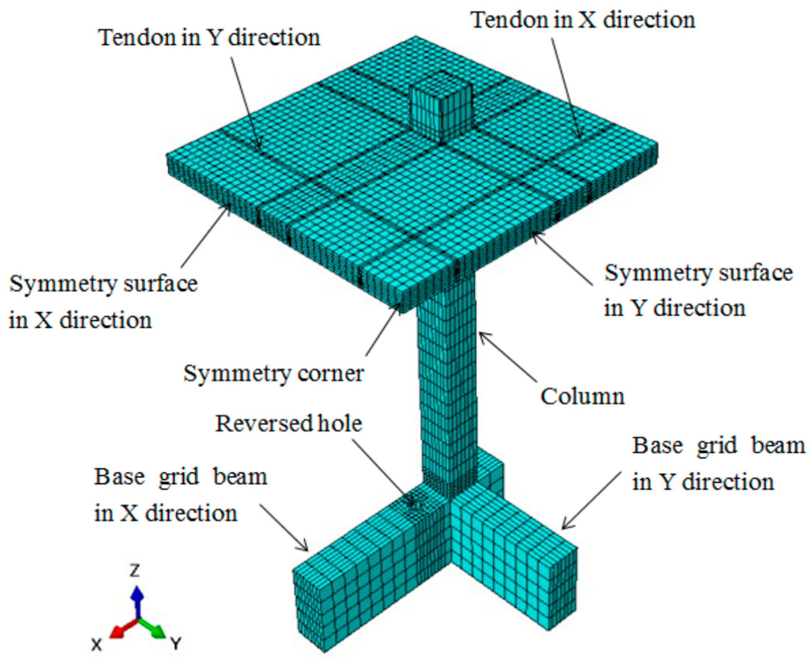
2.2. Numerical Model

FEMs were established based on the specimens of Test-1 and Test-2 as FE Model-1 and FE Model-2. The FE models were built up employing the package ABAQUS, using the 3D solid element C3D8R for modeling concrete and tendons, and the 3D truss element T3D2 for modeling non-prestressed reinforcement. Due to the symmetry of the specimen, only one-quarter of the specimen was modeled with a sufficient number of elements for accurate predictions (Figure 1), where symmetrical constraints were applied on the surfaces of symmetry, and other boundary conditions are identical to those of the tests.
The model proposed by Schneider [17] for normal-strength concrete is used to describe the stress–strain relationship of concrete exposed to elevated temperatures, as in Equation (1).
σ = 3 ε f c T ε o T 2 + ε ε o T 3
where σ c is the stress, ε c is the corresponding instantaneous strain, f c T is the compressive strength of concrete at temperature T (°C), and ε o T is the peak strain corresponding to f c T .
The concrete strength f c T at elevated temperature is obtained using the reduction factor k c based on the concrete strength f c at ambient temperature.
f c T = k c f c
where k c is taken from the tubular data for concrete with siliceous aggregate presented in BS EN 1992-1-2 [3].
The peak strain of concrete at elevated temperature is described by the model proposed by Terro [18], assuming zero initial stress, as follows.
ε o T = 2.05 × 10 3 + 3.08 × 10 6 T + 6.17 × 10 9 T 2 + 6.58 × 10 12 T 3
The model obtained based on the above-mentioned constitutive model, concrete strength, and peak strain at elevated temperature is hereafter called the Basic Model. The uniaxial stress–strain relationships of the Basic Model are obtained at various elevated temperatures. Comparison with the test data reported by Youssef and Moftah [19] and Gawin et al. [20] under various elevated temperatures shows good agreement, indicating that the Basic Model performs well in accounting for the instantaneous stress–strain relationships at elevated temperatures.
The thermal expansion strain at temperature is obtained from the thermal expansion strain of concrete with siliceous aggregate in BS EN 1992-1-2 [3], expressed as follows.
for   20   ° C T 700   ° C ε t h , c = 1.8 × 10 4 + 9 × 10 6 T + 2.3 × 10 11 T 3
for   700   ° C < T 1200   ° C ε t h , c = 14 × 10 3
The transient strain of concrete at elevated temperature is determined based on the empirical Equation (5) proposed by Nielsen [21], and the basic creep strain of concrete is determined by Equation (6). The lower bound parameters and middle parameters (mean of lower and upper limits of the parameters) of Nielsen’s model are separately used, denoted as Nielsen-lower and Nielsen-middle, correspondingly.
ε L I T S = σ c f c y y = A η 2 + B η f o r 0 η η * = 4.5 C η η * 2 + A 2 η η * + B η f o r   η > η *
where y is a function of temperature; η is a dimensionless variant depending on temperature by η = T 20 100 ; η * is a dimensionless constant as the transition at the temperature of 470 °C; and A , B , and C are parameters that can be identified through a test. By fitting the test data from Khoury [22,23] and Schneider [24], the parameters were identified as follows: A = 0.0004 , B = 0.001 , and C = 0.007 , providing the lower bound, and A = 0.0006 , B = 0.0015 , and C = 0.01 providing the upper bound [21]. The average of each of the parameters based on the lower bound and the upper bound (e.g., A = 0.0005 ) was adopted by Ožbolt et al. [25] for the transient analysis of concrete structures exposed to fire.
The model proposed by Harmathy, based on the test data obtained by Cruz [26], is adopted to describe the creep strain, namely
ε c r , c = β c r σ f c T t ¯ e d ( T ¯ 293 )
where β c r = 6.28 × 10 6   s 1 / 2 , d = 2.658 × 10 3   K 1 ,   t ¯ is the time in second, and T ¯ is the temperature of concrete in K.
The prestressing steel tendons used in the tests have a measured elastic modulus of 211 GPa, a yield strength (0.2% proof stress) of 1805 MPa, and an ultimate strength of 2008 MPa at ambient temperature [1]. The thermal creep strain is described by Equation (7), and the thermal creep parameters (Equations (8) and (9)) are taken for prestressing steel to GB/T 5224 [15], and the tertiary creep strain is incorporated as well.
ε c r = ε c r , 0 l n 2 c o s h 1 ( 2 Z θ / ε c r , 0 )
for   57   M P a σ < 950   M P a Z = 3.63155 × 10 16 e x p ( 0.50851 σ 0.56095 )
for . 950   M P a σ 1330   M P a Z = 6.8317 × 10 17 e x p ( 0.02199 σ )
ε c r , 0 = 0.00111 + 1.08242 × 10 15 σ 4.14132
The non-prestressed steel used in the tests has a measured elastic modulus of 190 GPa, yield strength of 248 MPa, and ultimate strength of 410 MPa for mild steel round bars of grade 235, and an elastic modulus of 196 GPa, yield strength of 458 MPa, and ultimate strength of 582 MPa for high yield steel deformed bars of grade 335. The mechanical properties at elevated temperatures are obtained based on the reduction factors and stress–strain constitutive model prescribed in BS EN 1992-1-2 [3].

3. Verification of FEM

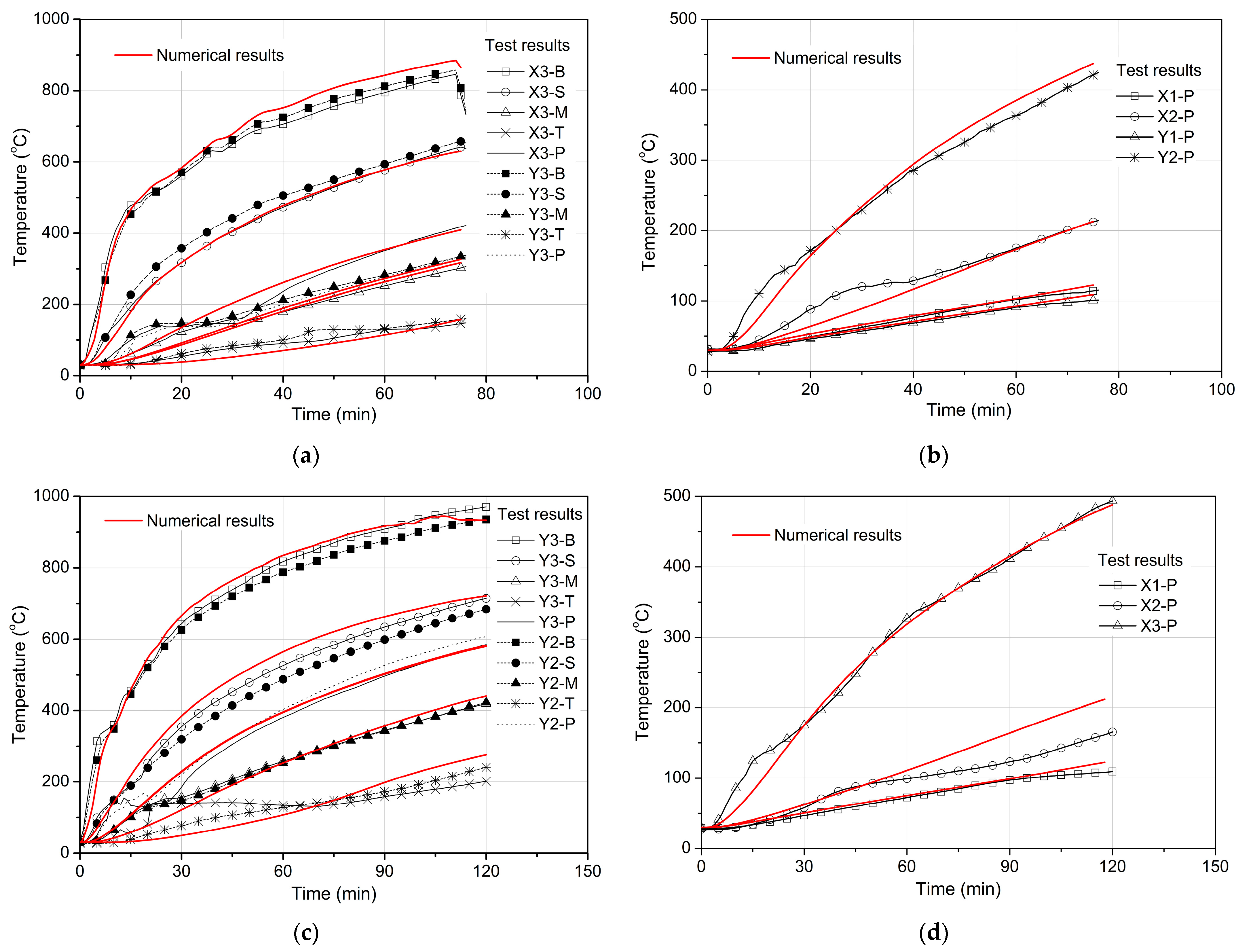
3.1. Temperature Field

Heat transfer analysis was conducted with the central part of the slab subjected to the furnace fire. The thermal properties of concrete, including thermal conductivity and specific heat, were taken from BS EN 1992-1-2 [3], and those of prestressing steel and non-prestressed steel were taken from BS EN 1993-1-2 [27]. The heat from the fire on the specimen was transferred through the process of convection and radiation, while the heat transferred inside the specimen was mainly through the process of thermal conductivity of materials.
The results obtained from heat transfer analysis were identical to those from the tests, as shown in Figure 2; excellent agreement was achieved. Figure 2a shows the temperature fields of the central panel of Test-1, and Figure 2b shows the temperatures of tendons distributed in the column strips of Test-1. These figures show minor discrepancies, except when there are temperature plateaus in the test results. The plateaus are mainly caused by water evaporation and melting of polypropylene sleeves, but this process is not considered in the modeling.

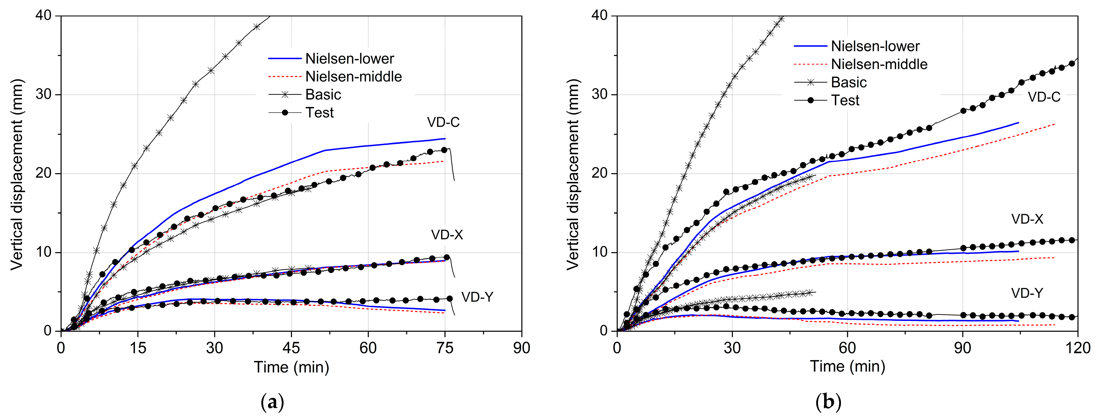
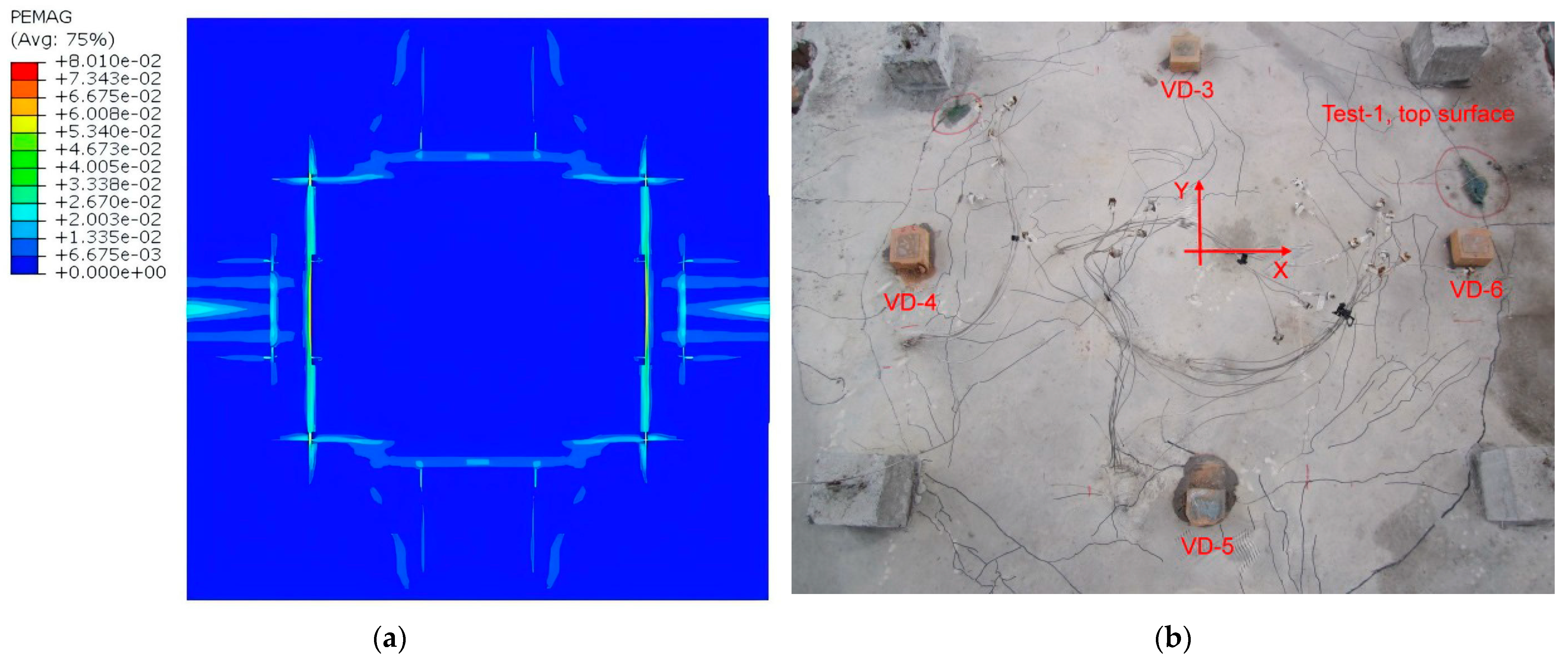
3.2. Structural Responses

In the numerical analysis, the Basic Model and the Transient Model (which explicitly considers transient creep strain by Equation (5)) for concrete were considered separately. The results obtained from the numerical modeling were compared with those obtained from the tests, as shown in Figure 3. VD-C indicates the vertical displacement of the central panel, VD-X indicates the vertical displacement of the middle of the column strip in the X direction, and similarly, VD-Y indicates the vertical displacement of the middle of the column strip in the Y direction. The results based on the Basic Model for VD-C, VD-X, and VD-Y are much larger than those of the tests, while the results based on the Transient Model coincide with those of the tests. This strongly suggests that the transient creep strain of concrete has significant effects on the structural responses of slabs under fire conditions. Appropriate consideration of the transient creep strain of concrete leads to accurate results. Moreover, the results based on Nielsen-lower and Nielsen-middle values show that the former are slightly larger than the latter. Also, the former achieves better agreement with the test results compared to the latter.
Figure 4 shows the crack patterns of the top surface of the slab of Test-1 obtained from numerical modeling and tests, where the former is represented by the crack strain contours obtained from numerical modeling based on the Transient Model with Nielsen-lower parameters, as shown in Figure 4a, and the latter shows the residual cracks of the slab after removing the loads and cooling to ambient temperature. Comparing the crack pattern in Figure 4a with that in Figure 4b, it can be found that both crack patterns are consistent, to some extent, as relatively large cracks appear in the column strips in the Y direction, small or micro-cracks appear in the column strips in the X direction, and the cracks in the surrounding panels in the test are also reflected by the crack strain contour of numerical modeling. However, there is a slight difference in the crack pattern, as the main cracks in the test approximately form an elliptic crack pattern, while the crack strain contour of numerical modeling approximately shows a rectangular crack pattern. The difference can possibly be attributed to the inaccurate modeling of the tensile crack behavior of concrete.
The comparison results of vertical displacements and crack patterns verified that the transient creep strain of concrete must not be ignored but should be considered explicitly. The FEMs were accurate based on the model with creep for prestressing steel and the Transient Model for concrete adopting Nielsen-lower parameters.

4. Parametric Study Results and Discussions

The factors considered in this parametric study include the tendon distributions, levels of prestressing, and areas of the slab subjected to fire. According to the difference in tendon distributions of Test-1 and Test-2, FE Model-1 and FE Model-2 were correspondingly established, based on which the other two factors were investigated in this study. The prestressing stresses were 0.3, 0.5, and 0.7, which were respectively denoted as P03, P05, and P07. The areas of slab subjected to fire, denoted as AF1, AF2, and AF3 for FE Model-1 and FE Model-2, are shown in Figure 5 and Figure 6. In FE Model-1, AF1 denotes the bottom area of the central panel of the slab, above which are tendons X3, X4, Y3, and Y4. AF2 denotes the bottom area, including the central panel and column strips, above which all the tendons lie, and AF-3 denotes the bottom area of the whole slab. In FE Model-2, AF1, AF2, and AF3 essentially denote the same areas as those in FE Model-1, except that only tendons Y3 and Y4 lie above AF1 in FE Model-2.

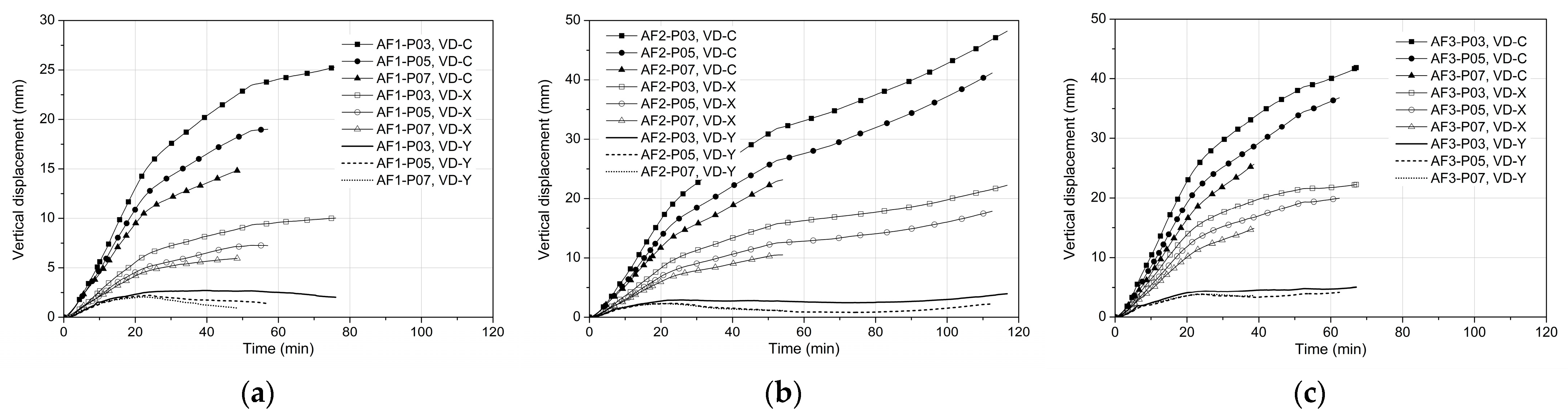
4.1. Effects of Tendon Distribution

The effects of tendon distribution on slab structural responses were investigated under diverse conditions, such as under the AF1-P03 combined condition (i.e., slab area AF1 was exposed to fire, and prestressing tendons had stress P03). Figure 7 presents a comparison of slab vertical displacements from numerical modeling based on FE Model-1 and FE Model-2. Tendon distribution has minimal impact on slab central deflection (VD-C) and a slight effect on mid-span X direction column strip deflection (VD-X). FE Model-1 generally yielded lower deflection than FE Model-2. Notably, for mid-span Y-direction column strip deflection (VD-Y), FE Model-1 mostly showed nearly twice the deflections as those of FE Model-2. Compared with distributed tendons, the X-direction banded tendons mainly apply compressive stresses to the X-direction column strip concrete, slightly reducing compressive stress at the central panel soffit in the X direction. This decreases the concrete transient creep strain in the X-direction under fire, making thermal flexural deformation larger in the X-direction than in the Y-direction. Consequently, the mid-span Y-direction column strip deflection decreases markedly, and the X-direction one increases slightly. Therefore, the tendon distribution can slightly affect the thermal flexural deformation by affecting the transient creep strain of concrete under fire conditions.

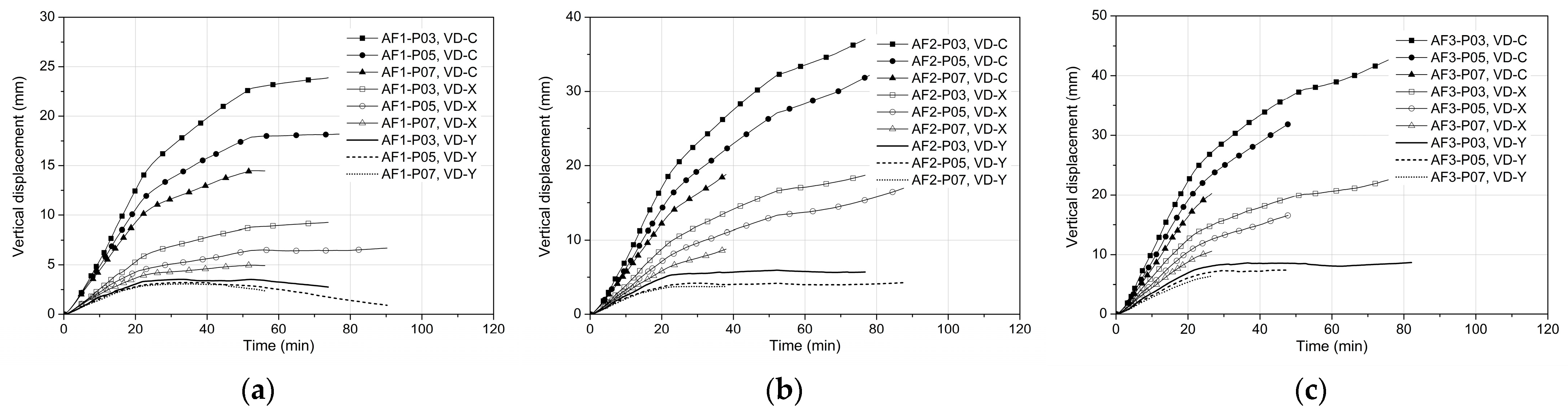
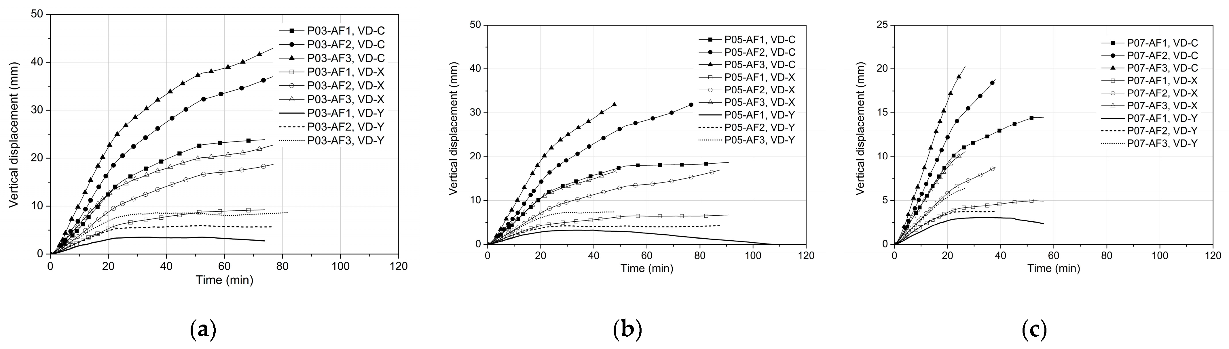
4.2. Effects of Level of Prestressing

The effects of the level of prestressing were investigated under various stresses of prestressing tendons (i.e., P03, P05, and P07) based on FE Model-1 and FE Model-2, with various areas of the slabs subjected to fire (i.e., AF1, AF2, and AF3). Figure 8 and Figure 9 show the comparisons of the vertical displacements of the slabs under various conditions based on FE Model-1 and FE Model-2, respectively. The level of prestressing has a significant effect on VD-C and VD-X. In general, increasing the tendon stresses leads to a decrease in the vertical displacements independent of the tendon distributions and areas of the slab subjected to fire. It has a minor effect on the mid-span deflection of the column strip in VD-Y. For example, P07 and P05 give nearly the same value of VD-Y, which is slightly lower than that given by P03. They are largely independent of the tendon distribution and areas of the slab subjected to fire. Increasing the tendon stresses of the slab, on the one hand, increases the balanced bending moment and results in reduced deflection. On the other hand, the increased tendon stresses provide larger compressive forces on the slab section, leading to an increase in the transient creep strain of concrete, which further reduces the deflection of the slab. This is possibly the main reason why the level of prestressing has a significant effect on the vertical deflections of the slabs.

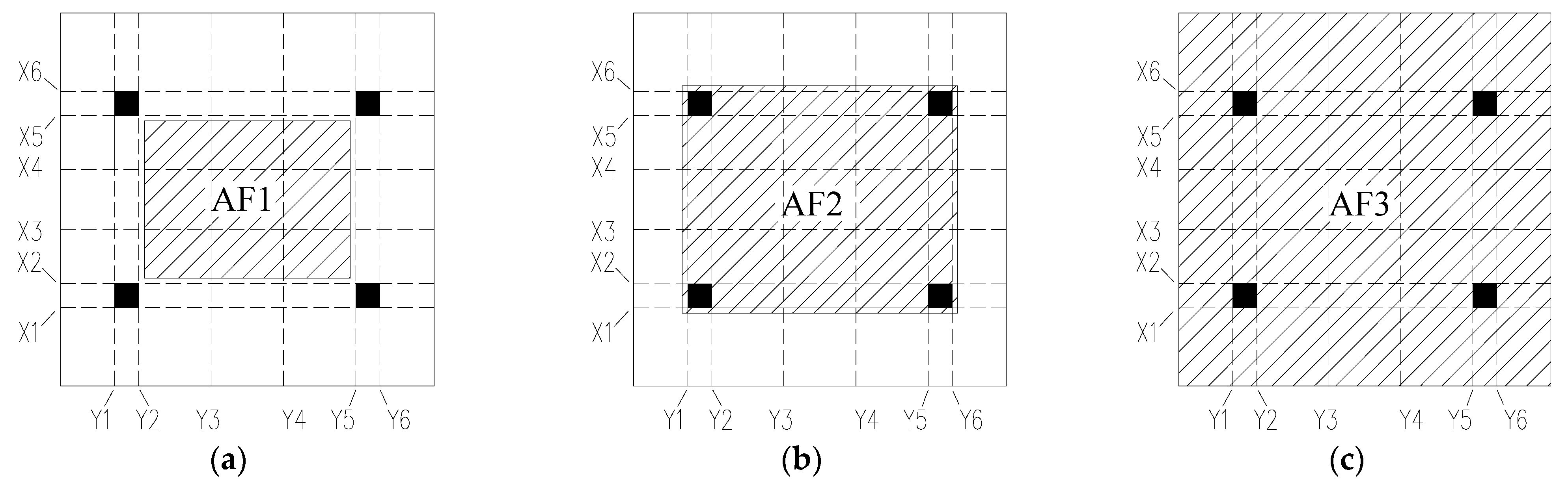
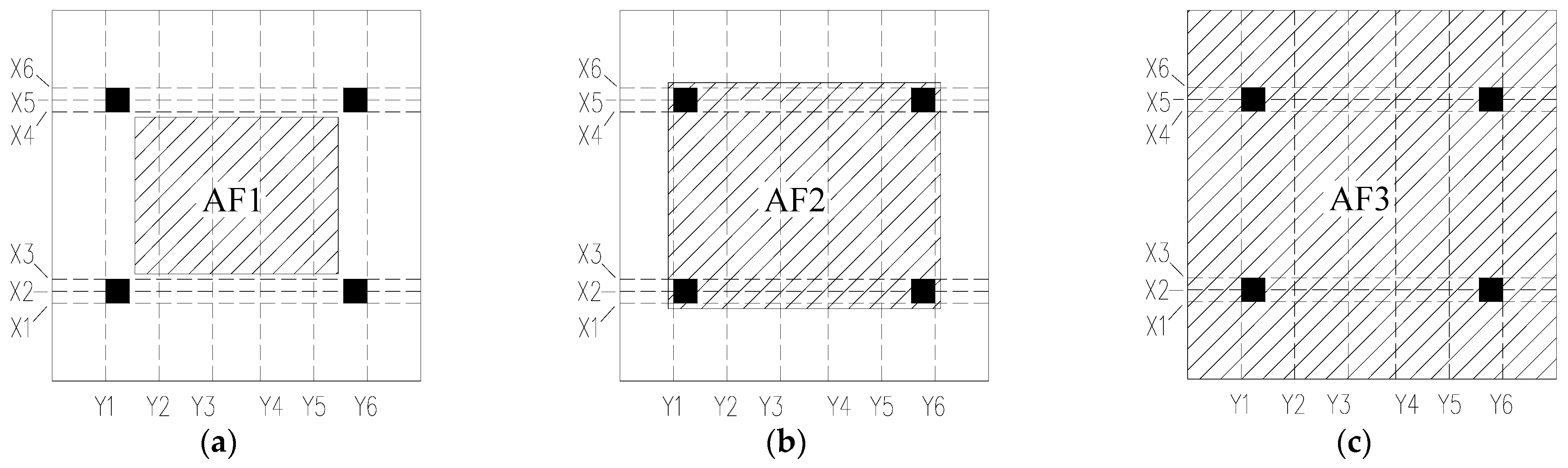
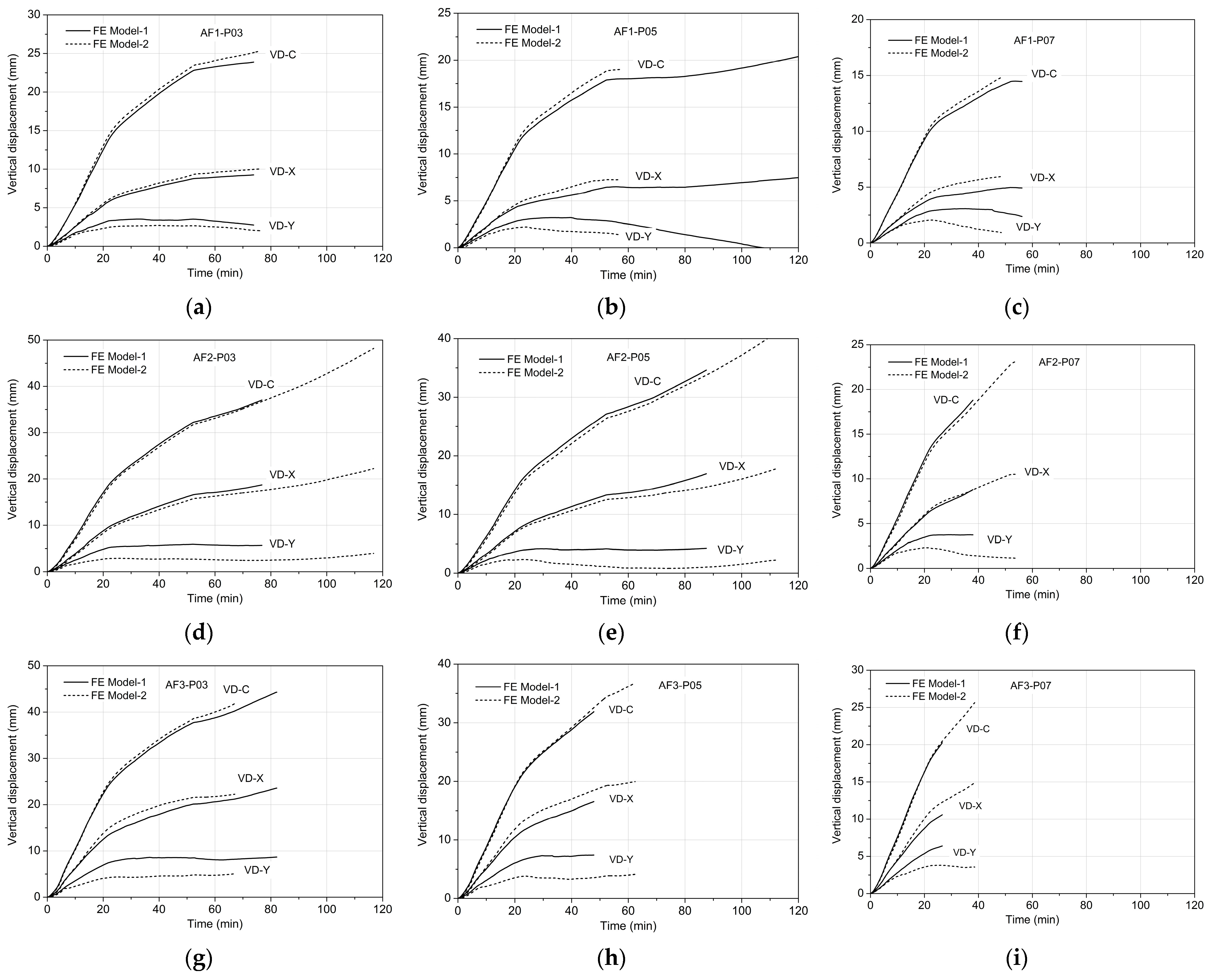
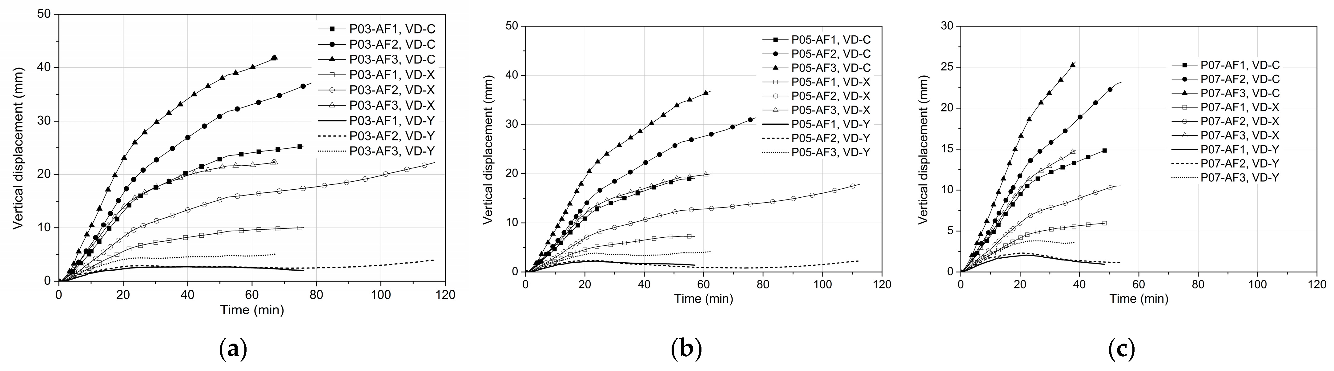
4.3. Effects of Areas Exposed to Fire

The effects of areas of the slabs exposed to fire were investigated by examining various cases (i.e., AF1, AF2, and AF3) based on FE Model-1 and FE Model-2. Figure 10 and Figure 11 show the comparison of vertical deflections of the slabs under various conditions based on FE Model-1 and FE Model-2, respectively.
The area of the slab exposed to fire has a significant effect on the vertical displacements of the slabs, including VD-C, VD-X, and VD-Y. The case of the bottom area of the central panel of the slab exposed to fire (AF1) enables the smallest deflections, while the case of the whole bottom area of the slab exposed to fire (AF3) shows the largest deflections. Moreover, with the increase in the area exposed to fire, the deflection increases as well.
The thermal gradient and subsequent thermal expansion across the slab depth cause thermal bowing, leading to slab flexural deformation. In AF1, the mid-span deflections of VD-X and VD-Y result from the central panel’s flexural deformation. To an extent, the surrounding cold column strips and panels restrain this flexural deformation. In AF2, due to column strip thermal bowing, restraint on slab flexural deformation reduces greatly, increasing the central and mid-span deflections of column strips, though the deformation is still partly restrained by surrounding cold panels. In AF3, as the surrounding panels thermally bow, the restraint on column strips and central panel flexural deformations also lessen significantly, boosting central and mid-span deflections of column strips. Therefore, slab deflections generally rise with an increase in the bottom fire-exposed areas of the slabs.
Furthermore, the behavior of slab tendons under various conditions, such as P03-AF1, was studied based on FE Model-1. Figure 12 shows the changes in tendon stresses and temperatures over time. In the early fire stage, tendon stresses rise faster in cases with larger fire-exposed areas. This is because a larger area leads to greater slab deflections, causing tendon elongation and stress increase. Subsequently, tendon stresses either rise slowly or decline gradually due to thermal relaxation from elastic modulus degradation, thermal expansion, and thermal creep. Otherwise, they drop suddenly because of tertiary creep strain or plastic strain after yielding.
As shown in Figure 12, the stresses of most tendons begin to decrease at about 300 °C, and the larger the initial stresses are, the faster the stresses decrease. Specifically, comparing Figure 12a,c, the stress of “P05-AF1, X3” decreases faster than that of “P03-AF1, X3”. Several tendons yield due to the relatively high stresses at elevated temperatures, resulting in an abrupt decrease in stress, such as “P05-AF3, X1”, “P05-AF3, X2”, and “P05-AF3, X3” (Figure 12c). Tendon yielding mainly occurs in the slabs with large areas exposed to fire and the tendons with relatively high initial stresses, especially above 1000 MPa. It indicates that a larger area exposed to fire or larger initial tendon stresses results in shorter fire resistance of the slabs if tendon yielding is defined as a failure criterion of the slabs under fire. Therefore, it is recommended that the bottom area of the column strips must be protected from fire by fire coatings or fire boards, and initial tendon stresses must be kept lower (e.g., not exceeding 1000 MPa).

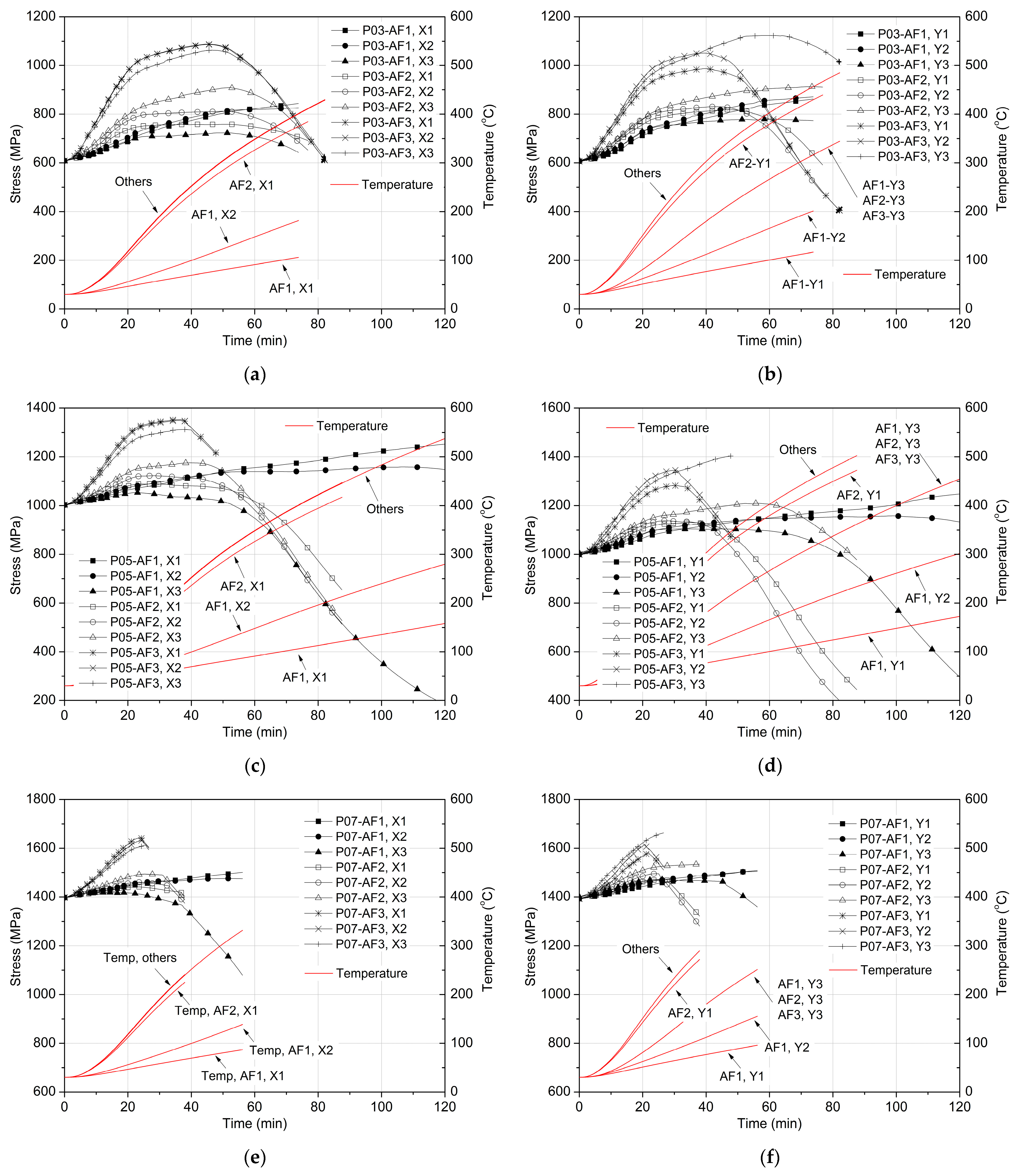
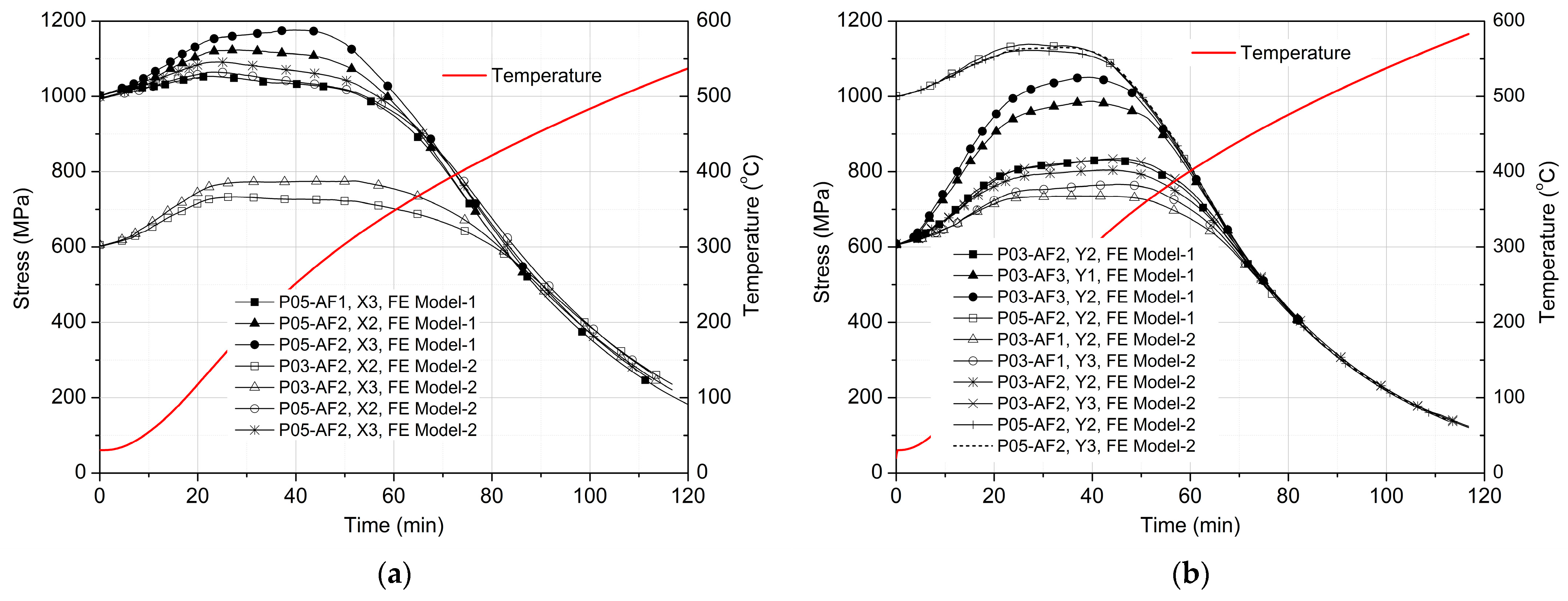
4.4. Variations in Stresses of Tendons in the Same Profile

Some tendons have the same tendon profiles, such as X1, X2, and X3 in FE Model-1 and FE Model-2, Y1 and Y2 in FE Model-1, and Y2 and Y3 in FE Model-2. When the bottom area of the slab below tendons with the same tendon profile is exposed to fire, the tendons experience the same temperature field. Stresses of these tendons with roughly the same temperature field are compared, as shown in Figure 13. The stresses of tendons in the X-direction are described in Figure 13a, while Figure 13b shows the stresses of tendons in the Y-direction. The profile in the X-direction has a minimum axial distance from the center line of the tendon to the soffit of the slab of 34 mm, and the profile in the Y-direction has a minimum value of 28 mm [1].
Figure 13 shows that the tendon stresses increase initially due to thermal bowing-induced elongation of tendons and then gradually decrease due to thermal relaxation. The stress–time curves of all the tendons drop and finally converge to a common curve, at a converging point with a stress of about 600 MPa and a temperature of 425 °C. Beyond the converging point, the tendon stresses are nearly independent of the initial stresses but depend on the temperature field of the tendons. The interesting phenomenon of the tendons at elevated temperatures was observed and presented by Wei and Au [28]. The phenomenon exists even if the interaction between the tendons and the slab is considered. Therefore, if the temperature fields of the tendons of the slabs are known, the tendon stresses in the dropping stage can be predicted by the model proposed by Wei and Au [28]. At the temperature of 500 °C, the tendon stresses decreased to about 300 MPa, and at this point, most of the stresses disappeared.

5. Conclusions

A numerical model of PT concrete flat slabs with unbonded tendons was constructed by employing ABAQUS. Nonlinear FE models were established based on test specimens and loading conditions, where various material models for concrete and prestressing steel were taken into account. The models were verified in the temperature field and structural responses. Parametric studies were conducted by taking into consideration tendon distribution, level of prestressing, and area of the slab soffit exposed to fire. The results are summarized as follows.
  • The considered tendon distributions slightly influence the mid-span column strip deflection due to the concrete transient creep strain under fire.
  • The prestressing level has a significant effect on the vertical deflections of the slabs under fire. Increasing the level increases the transient creep strain of concrete and the balanced load provided by prestressing tendons, further resulting in a decrease in deflections.
  • The fire-exposed area of the slab soffit strongly affects the vertical deflections. Enlarging this area loosens the surrounding panel restraints on the central panel flexural deformation, increasing deflections.
  • High initial tendon stresses cause the tendon to yield early in the fire, leading to a sudden stress drop and lower fire resistance of the slabs.
  • Tendon stresses start to decline gradually from 300 °C and drop faster as the temperature climbs. Similar temperature field stress–time curves tend to merge into a common one.
  • The dropping-stage tendon stresses can be estimated using the common curve when the temperature field and initial stresses are known, without accounting for slab deformation interactions.

Author Contributions

Conceptualization, F.T.K.A. and Y.W.; methodology, Y.W.; software, Y.W.; validation, Y.W. and D.F.; resources, D.F.; data curation, Y.W.; writing—original draft preparation, Y.W.; writing—review and editing, D.F.; funding acquisition, F.T.K.A. All authors have read and agreed to the published version of the manuscript.

Funding

The work described here has been supported by the ResearchGrants Council (RGC) of Hong Kong Special Administrative Region, China (RGC Project No.: HKU 710012E) and the State Key Laboratory of Subtropical Building Science of South China University of Technology, China (Project No.: 2011KA02).

Institutional Review Board Statement

Not applicable.

Informed Consent Statement

Not applicable.

Data Availability Statement

All the data is described in the paper.

Conflicts of Interest

The authors declare no conflict of interest.

References

  1. Wei, Y.; Au, F.T.K.; Li, J.; Tsang, N.M.C. Experimental and numerical investigation of post-tensioned concrete flat slabs in fire. J. Struct. Fire Eng. 2016, 7, 2–18. [Google Scholar] [CrossRef]
  2. ACI 318-08; Building Code Requirements for Structural Concrete and Commentary, ACI Standard. American Concrete Institute: Farmington Hills, MI, USA, 2008.
  3. BS EN 1992-1-2; Eurocode 2: Design of Concrete Structures—Part 1–2: General Rules—Structural Fire Design. British Standards Institution: London, UK, 2023.
  4. Gustaferro, A.H. Fire resistance of post-tensioned structures. J. Prestress. Concr. Inst. 1973, 18, 38–63. [Google Scholar] [CrossRef]
  5. Gales, J.; Bisby, L.A.; Gillie, M. Unbonded post tensioned concrete in fire: A review of data from furnace tests and real fires. Fire Saf. J. 2011, 46, 151–163. [Google Scholar] [CrossRef]
  6. Yuan, A.M.; Dong, Y.L.; Gao, L.T. Behavior of unbonded prestressed continuous concrete slabs with the middle and edge span subjected to fire in sequence. Fire Saf. J. 2013, 56, 20–29. [Google Scholar]
  7. Zheng, W.Z.; Hou, X.M.; Shi, D.S.; Xu, M.X. Experimental study on concrete spalling in prestressed slabs subjected to fire. Fire Saf. J. 2010, 45, 283–297. [Google Scholar] [CrossRef]
  8. Ellobody, E.; Bailey, C. Behaviour of Unbonded Post-Tensioned One-way Concrete Slabs. Adv. Struct. Eng. 2008, 11, 107–120. [Google Scholar] [CrossRef]
  9. Gillie, M.; Usmani, A.S.; Rotter, J.M. A structural analysis of the first Cardington test. J. Constr. Steel Res. 2001, 57, 581–601. [Google Scholar] [CrossRef]
  10. Gillie, M.; Usmani, A.S.; Rotter, J.M. A structural analysis of the Cardington British steel corner test. J. Constr. Steel Res. 2002, 58, 427–442. [Google Scholar] [CrossRef]
  11. Mirza, O.; Uy, B. Behaviour of headed stud shear connectors for composite steel-concrete beams at elevated temperatures. J. Constr. Steel Res. 2009, 65, 662–674. [Google Scholar] [CrossRef]
  12. Ellobody, E.; Bailey, C.G. Modeling of bonded post-tensioned concrete slabs in fire. Proc. Inst. Civ. Eng. Struct. Build. 2008, 161, 311–323. [Google Scholar] [CrossRef]
  13. Ellobody, E.; Bailey, C.G. Modeling of unbonded post-tensioned concrete slabs under fire conditions. Fire Saf. J. 2009, 44, 159–167. [Google Scholar] [CrossRef]
  14. Bailey, C.G.; Ellobody, E. Whole-building behaviour of bonded post-tensioned concrete floor plates exposed to fire. Eng. Struct. 2009, 31, 1800–1810. [Google Scholar] [CrossRef]
  15. Wei, Y.; Au, F.T.K.; Li, J.; Tsang, N.M.C. Effects of transient creep strain on post-tensioned concrete slabs in fire. Mag. Concr. Res. 2017, 69, 337–346. [Google Scholar] [CrossRef]
  16. Wei, Y.; Zhang, L.; Au, F.T.K.; Li, J.; Tsang, N.M.C. Thermal creep and relaxation of prestressing steel. Constr. Build. Mater. 2016, 128, 118–127. [Google Scholar] [CrossRef]
  17. Schneider, U.; Schneider, M. An advanced transient concrete model for the determination of restraint in concrete structures subjected to fire. J. Adv. Concr. Technol. 2009, 7, 403–413. [Google Scholar] [CrossRef]
  18. Terro, M.J. Numerical modeling of the behavior of concrete structures in fire. ACI Struct. J. 1998, 95, 183–193. [Google Scholar]
  19. Youssef, M.A.; Moftah, M. General stress-strain relationship for concrete at elevated temperatures. Eng. Struct. 2007, 29, 2618–2634. [Google Scholar] [CrossRef]
  20. Gawin, D.; Pesavento, F.; Schrefler, B.A. Modeling of deformations of high strength concrete at elevated temperatures. Mater. Struct. 2004, 37, 218–236. [Google Scholar] [CrossRef]
  21. Pearce, C.J.; Nielsen, C.V.; Bicanic, N. Gradient enhanced thermo-mechanical damage model for concrete at high temperatures including transient thermal creep. Int. J. Numer. Anal. Methods Geomech. 2004, 28, 715–735. [Google Scholar] [CrossRef]
  22. Khoury, G.A.; Grainger, B.N.; Sullivan, P.J.E. Transient thermal strain of concrete: Literature review, conditions within specimen and behaviour of individual constituent. Mag. Concr. Res. 1985, 37, 131–144. [Google Scholar] [CrossRef]
  23. Khoury, G.A.; Grainger, B.N.; Sullivan, P.J.E. Strain of concrete during first heating to 600 °C under load. Mag. Concr. Res. 1985, 37, 195–215. [Google Scholar] [CrossRef]
  24. Schneider, U. Concrete at high temperatures—A general review. Fire Saf. J. 1986, 13, 55–68. [Google Scholar] [CrossRef]
  25. Ožbolt, J.; Bošnjaka, J.; Periškic, G.; Sharma, A. 3D numerical analysis of reinforced concrete beams exposed to elevated temperature. Eng. Struct. 2014, 58, 166–174. [Google Scholar] [CrossRef]
  26. Cruz, C.R. Apparatus for measuring creep of concrete at high temperatures. J. PCA Res. Dev. Lab. 1968, 10, 36–42. [Google Scholar]
  27. BS EN 1991-1-2; Eurocode 1: Actions on Structures—Part 1–2: General Actions—Actions on Structures Exposed to Fire. British Standards Institution: London, UK, 2002.
  28. Wei, Y.; Au, F.T.K. Numerical Modeling of Prestresssing Steel Tendons under Fire and Post-Fire Conditions. Adv. Struct. Eng. 2015, 18, 1703–1722. [Google Scholar] [CrossRef]
Figure 1. Finite element model for one-quarter of specimens of Test-1.
Engproc 98 00031 g001
Figure 2. Comparison of temperature field and tendon temperature obtained from numerical modeling and tests: (a) temperature field of Test-1, (b) tendon temperature of Test-1, (c) temperature field of Test-2, and (d) tendon temperature of Test-2.
Engproc 98 00031 g002
Figure 3. Comparison of vertical displacements of the slabs obtained from numerical modeling and tests: (a) vertical displacements of Test-1 and (b) vertical displacements of Test-2.
Engproc 98 00031 g003
Figure 4. Crack pattern of top surface of the slab of Test-1 subjected to fire: (a) numerical modeling and (b) testing.
Engproc 98 00031 g004
Figure 5. Areas of slab subjected to fire based on FE Model-1: (a) AF1, (b) AF2, and (c) AF3.
Engproc 98 00031 g005
Figure 6. Areas of slab subjected to fire based on FE Model-2: (a) AF1, (b) AF2, and (c) AF3.
Engproc 98 00031 g006
Figure 7. Comparison of vertical displacements of FE Model-1 and FE Model-2: (a) Case AF1-P03, (b) Case AF1-P05, (c) Case AF1-P07, (d) Case AF2-P03, (e) Case AF2-P05, (f) Case AF2-P07, (g) Case AF3-P03, (h) Case AF3-P05, and (i) Case AF3-P07.
Engproc 98 00031 g007
Figure 8. Comparison of vertical displacements of slabs under various levels of prestressing based on FE Model-1, (a) Case AF1, (b) Case AF2, (c) Case AF3.
Engproc 98 00031 g008
Figure 9. Comparison of vertical displacements of slabs under various levels of prestressing based on FE Model-2: (a) AF1, (b) AF2, and (c) AF3.
Engproc 98 00031 g009
Figure 10. Comparison of vertical displacements of slabs with various areas subjected to fire based on FE Model-1: (a) Case P03, (b) Case P05, and (c) Case P07.
Engproc 98 00031 g010
Figure 11. Comparison of vertical displacements of slabs with various areas subjected to fire based on FE Model-2: (a) Case P03, (b) Case P05, and (c) Case P07.
Engproc 98 00031 g011
Figure 12. Comparison of tendon stresses of slabs with various areas subjected to fire based on FE Model-1: (a) in X-direction with P03, (b) in Y-direction with P03, (c) in X-direction with P05, (d) in Y-direction with P05, (e) in X-direction with P07, and (f) in Y-direction with P07.
Engproc 98 00031 g012
Figure 13. Stresses of tendons with the same profiles: (a) X-direction and (b) Y-direction.
Engproc 98 00031 g013
Table 1. Design parameters of test specimens.
Test CaseTendon DistributionDesign Prestressing LevelDesign Loading Ratio
Test-1Distributed–Distributed0.370.50
Test-2Banded–Distributed0.500.35
Test-3Distributed–Distributed0.500.50
Test-4Banded–Distributed0.500.35
Disclaimer/Publisher’s Note: The statements, opinions and data contained in all publications are solely those of the individual author(s) and contributor(s) and not of MDPI and/or the editor(s). MDPI and/or the editor(s) disclaim responsibility for any injury to people or property resulting from any ideas, methods, instructions or products referred to in the content.

